DE102013221659A1 - Arrangement for providing an inductive charging connection - Google Patents
Arrangement for providing an inductive charging connectionDownload PDFInfo
- Publication number
- DE102013221659A1 DE102013221659A1DE201310221659DE102013221659ADE102013221659A1DE 102013221659 A1DE102013221659 A1DE 102013221659A1DE 201310221659DE201310221659DE 201310221659DE 102013221659 ADE102013221659 ADE 102013221659ADE 102013221659 A1DE102013221659 A1DE 102013221659A1
- Authority
- DE
- Germany
- Prior art keywords
- coil
- arrangement according
- substrate
- metal structure
- frequency
- Prior art date
- Legal status (The legal status is an assumption and is not a legal conclusion. Google has not performed a legal analysis and makes no representation as to the accuracy of the status listed.)
- Ceased
Links
Images

Classifications
- H—ELECTRICITY
- H01—ELECTRIC ELEMENTS
- H01F—MAGNETS; INDUCTANCES; TRANSFORMERS; SELECTION OF MATERIALS FOR THEIR MAGNETIC PROPERTIES
- H01F38/00—Adaptations of transformers or inductances for specific applications or functions
- H01F38/14—Inductive couplings
- H—ELECTRICITY
- H01—ELECTRIC ELEMENTS
- H01F—MAGNETS; INDUCTANCES; TRANSFORMERS; SELECTION OF MATERIALS FOR THEIR MAGNETIC PROPERTIES
- H01F27/00—Details of transformers or inductances, in general
- H01F27/34—Special means for preventing or reducing unwanted electric or magnetic effects, e.g. no-load losses, reactive currents, harmonics, oscillations, leakage fields
- H01F27/36—Electric or magnetic shields or screens
- H01F27/363—Electric or magnetic shields or screens made of electrically conductive material
- H—ELECTRICITY
- H01—ELECTRIC ELEMENTS
- H01F—MAGNETS; INDUCTANCES; TRANSFORMERS; SELECTION OF MATERIALS FOR THEIR MAGNETIC PROPERTIES
- H01F27/00—Details of transformers or inductances, in general
- H01F27/34—Special means for preventing or reducing unwanted electric or magnetic effects, e.g. no-load losses, reactive currents, harmonics, oscillations, leakage fields
- H01F27/36—Electric or magnetic shields or screens
- Y—GENERAL TAGGING OF NEW TECHNOLOGICAL DEVELOPMENTS; GENERAL TAGGING OF CROSS-SECTIONAL TECHNOLOGIES SPANNING OVER SEVERAL SECTIONS OF THE IPC; TECHNICAL SUBJECTS COVERED BY FORMER USPC CROSS-REFERENCE ART COLLECTIONS [XRACs] AND DIGESTS
- Y02—TECHNOLOGIES OR APPLICATIONS FOR MITIGATION OR ADAPTATION AGAINST CLIMATE CHANGE
- Y02T—CLIMATE CHANGE MITIGATION TECHNOLOGIES RELATED TO TRANSPORTATION
- Y02T10/00—Road transport of goods or passengers
- Y02T10/60—Other road transportation technologies with climate change mitigation effect
- Y02T10/70—Energy storage systems for electromobility, e.g. batteries
Landscapes
- Engineering & Computer Science (AREA)
- Power Engineering (AREA)
- Shielding Devices Or Components To Electric Or Magnetic Fields (AREA)
Abstract
Translated fromGermanDescription
Translated fromGermanDie Erfindung betrifft eine Anordnung zur Bereitstellung einer induktiven Ladeverbindung.The invention relates to an arrangement for providing an inductive charging connection.
Für das kontaktlose Laden eines Elektrofahrzeugs wird ein Spulensystem verwendet, das aus einer stationären Primärspule auf dem Boden und einer Sekundärspule am Elektrofahrzeug besteht. Hierbei erzeugt das Spulensystem ein magnetisches Wechselfeld, welches Energie zum Elektrofahrzeug überträgt. Zwischen beiden Spulen verbleibt in der Regel ein Luftspalt im Bereich von ca. 70–150 cm, der überwacht werden muss. Der Ladevorgang kann im Stand oder auch während der Fahrt erfolgen; in letzterem Fall wird eine Vielzahl stationärer Primärspulen in den Straßenbelag eingebettet.For the contactless charging of an electric vehicle, a coil system is used, which consists of a stationary primary coil on the ground and a secondary coil on the electric vehicle. In this case, the coil system generates a magnetic alternating field, which transmits energy to the electric vehicle. Between the two coils usually remains an air gap in the range of about 70-150 cm, which must be monitored. The charging process can be done while stationary or while driving; in the latter case, a plurality of stationary primary coils embedded in the pavement.
Aus der
Aus der
Aus der
Durch die vorliegende Erfindung soll eine Anordnung zur Bereitstellung einer induktiven Ladeverbindung geschaffen werden, welche eine Alternative zu den aus dem Stand der Technik bekannten Vorrichtungen bereitstellt.The present invention is intended to provide an arrangement for providing an inductive charging connection which provides an alternative to the devices known from the prior art.
Diese Aufgabe wird erfindungsgemäß durch eine Anordnung gelöst, welche eine erste Spule umfasst, welche geeignet ist, eine induktive Ladeverbindung im kHz-Bereich mit einer zweiten Spule herzustellen, wobei die zweite Spule nicht notwendigerweise von der Anordnung umfasst ist, und wobei die erste Spule insbesondere einen Ferrit umschließt.This object is achieved by an arrangement comprising a first coil, which is adapted to produce an inductive charging connection in the kHz range with a second coil, wherein the second coil is not necessarily included in the arrangement, and wherein the first coil in particular enclosing a ferrite.
Die Anordnung ist gekennzeichnet durch eine frequenzselektive Schirmung für die erste Spule, welche Frequenzen im MHz-Bereich und/oder im GHz-Bereich abschirmt, ohne Frequenzen im kHz-Bereich zu beeinträchtigen.The arrangement is characterized by a frequency-selective shield for the first coil, which shields frequencies in the MHz range and / or in the GHz range, without affecting frequencies in the kHz range.
Beispiele für den kHz-Bereich sind 1–999 kHz, sowie beliebige Ausschnitte in dem Bereich von 1–999 kHz, etwa 20–50 kHz, 20–100kHz. Beispiele für den MHz-Bereich sind 1–999 MHz, sowie beliebige Ausschnitte in dem Bereich von 1–999 MHz, etwa 20–50 MHz, 20–100MHz. Beispiele für den GHz-Bereich sind 1–999 GHz, sowie beliebige Ausschnitte in dem Bereich von 1–999 GHz, etwa 76–77 GHz, 50–100 GHz, 20–100GHz.Examples of the kHz range are 1-999 kHz, as well as any cuts in the range of 1-999 kHz, about 20-50 kHz, 20-100 kHz. Examples of the MHz range are 1-999 MHz, as well as any slices in the range of 1-999 MHz, about 20-50 MHz, 20-100 MHz. Examples of the GHz range are 1-999 GHz, as well as any cuts in the range of 1-999 GHz, about 76-77 GHz, 50-100 GHz, 20-100 GHz.
Die im Folgenden genannten Vorteile müssen nicht notwendigerweise durch den Gegenstand des unabhängigen Patentanspruchs erzielt werden. Vielmehr kann es sich hierbei auch um Vorteile handeln, welche lediglich durch einzelne Ausführungsformen, Varianten oder Weiterbildungen erzielt werden.The advantages mentioned below need not necessarily be achieved by the subject-matter of the independent patent claim. Rather, these may also be advantages, which are achieved only by individual embodiments, variants or developments.
In den Spulen induktiver Ladesysteme werden in der Regel Ferrite eingesetzt. Die frequenzselektive Schirmung der Anordnung ermöglicht es, diese Ferrite für hohe Frequenzen (MHz- und/oder GHz-Bereich) abzuschirmen, ohne die induktive Ladefunktionalität im niedrigen Frequenzbereich (kHz-Bereich) zu stören. Die Anordnung erlaubt damit erstmals auch dann den Einsatz von Radarverfahren, welche mit Frequenzen im MHz-GHz-Bereich arbeiten, wenn die induktive Ladeverbindung mit voller Leistung arbeitet. Die frequenzselektive Schirmung verhindert, dass die Empfindlichkeit der Detektionsantennen bei hohen Frequenzen durch die Ferrite in der Primär- wie auch in der Sekundärspule heruntergesetzt wird. Dadurch ist mit diesen Antennen eine Detektion von Gegenständen im Luftspalt selbst dann noch möglich, wenn die induktive Ladeverbindung mit voller Leistung arbeitet.In the coils of inductive charging systems ferrites are usually used. The frequency-selective shielding of the arrangement makes it possible to shield these ferrites for high frequencies (MHz and / or GHz range) without disturbing the inductive charging functionality in the low frequency range (kHz range). The arrangement allows for the first time the use of radar, which operate at frequencies in the MHz GHz range, when the inductive charging connection operates at full power. The frequency-selective shielding prevents the sensitivity of the detection antennas from being lowered at high frequencies by the ferrites in the primary as well as in the secondary coil. As a result, it is still possible with these antennas to detect objects in the air gap even when the inductive charging connection is operating at full power.
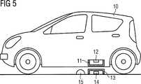
Gemäß einer Ausführungsform ist die erste Spule eine stationäre Primärspule, die zweite Spule eine fahrzeugseitige Sekundärspule in einem Elektrofahrzeug und die frequenzselektive Schirmung eine stationäre Schirmung für die stationäre Primärspule. Alternativ ist die erste Spule eine fahrzeugseitige Sekundärspule in einem Elektrofahrzeug, die zweite Spule eine stationäre Primärspule und die frequenzselektive Schirmung eine fahrzeugseitige Schirmung für die fahrzeugseitige Sekundärspule.According to one embodiment, the first coil is a stationary primary coil, the second coil is a vehicle-side secondary coil in an electric vehicle and the frequency-selective shielding is a stationary shield for the stationary primary coil. Alternatively, the first coil is a vehicle-side secondary coil in an electric vehicle, the second coil a stationary primary coil and the frequency-selective shielding a vehicle-side shield for the vehicle-side secondary coil.
In einer Weiterbildung ist ein Detektionsmittel zur Überwachung eines Zwischenraums zwischen der ersten Spule und der zweiten Spule vorgesehen, welches für Frequenzen im MHz-Bereich und/oder im GHz-Bereich eingerichtet und außerhalb der frequenzselektiven Schirmung angeordnet ist.In a development, a detection means for monitoring a gap between the first coil and the second coil is provided, which is set up for frequencies in the MHz range and / or in the GHz range and arranged outside the frequency-selective shielding.
Gemäß einer Ausführungsform ist das Detektionsmittel ein Radar, insbesondere ein Doppler-Radar oder ein FMCW-Radar. According to one embodiment, the detection means is a radar, in particular a Doppler radar or an FMCW radar.
In einer Weiterbildung beinhaltet das Detektionsmittel eine Patchantenne oder eine Dipolantenne.In one development, the detection means includes a patch antenna or a dipole antenna.
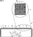
Gemäß einer Ausführungsform beinhaltet die frequenzselektive Schirmung zumindest ein Substrat, wobei auf zumindest einer Seite des zumindest einen Substrats eine Metallstruktur angeordnet ist, wobei die Metallstruktur mehrere nicht zusammenhängende Teilbereiche umfasst, und wobei die Teilbereiche der Metallstruktur zumindest teilweise kapazitiv miteinander verbunden sind.According to one embodiment, the frequency-selective shielding includes at least one substrate, wherein a metal structure is arranged on at least one side of the at least one substrate, wherein the metal structure comprises a plurality of non-contiguous subregions, and wherein the subregions of the metal structure are at least partially capacitively interconnected.
Die erzeugte kapazitive Kopplung stellt für hohe Frequenzen einen Kurzschluss und für niedrige Frequenzen einen Leerlauf dar. Somit ergibt sich eine frequenzselektive Oberfläche, die eine Tiefpasscharakteristik aufweist.The generated capacitive coupling represents a short circuit for high frequencies and an idling for low frequencies. Thus, a frequency-selective surface results, which has a low-pass characteristic.
Die Ausführungsform hat den Vorteil, dass durch das Substrat und die Strukturierung der Metalloberfläche eine frequenzselektive Oberfläche erzielt werden kann, die hochfrequente Störfrequenzen abschirmt. Ein weiterer Vorteil besteht darin, dass die frequenzselektive Schirmung durch strukturierte Metalloberfläche (z.B. eine Schlitzung) für Frequenzen im kHz-Bereich durchlässig wird. Zusätzlich können diskrete Kapazitäten eingesetzt werden, um Teile der Metallstruktur zu verbinden. Gerade durch die Kombination der Ansätze ergibt sich eine hohe Flexibilität hinsichtlich der Bauform der abschirmenden Struktur sowie der Frequenzen, die abgeschirmt werden sollen.The embodiment has the advantage that a frequency-selective surface can be achieved by the substrate and the structuring of the metal surface, which shields high-frequency interference frequencies. Another advantage is that the frequency-selective shielding becomes permeable by structured metal surface (e.g., a slit) for frequencies in the kHz range. In addition, discrete capacitances can be used to connect parts of the metal structure. Precisely because of the combination of the approaches, there is a high degree of flexibility with regard to the design of the shielding structure and the frequencies which are to be shielded.
Somit wird erreicht, dass die Abschirmung für die erste Spule bzw. ihren Ferrit im MHz- und/oder GHz-Bereich möglichst hoch und im kHz-Bereich möglichst transparent ist.It is thus achieved that the shield for the first coil or its ferrite in the MHz and / or GHz range is as high as possible and as transparent as possible in the kHz range.
Gemäß einer Ausführungsform umfasst die Schirmung zumindest ein Substrat, wobei auf zumindest einer Seite des zumindest einen Substrats eine Metallstruktur angeordnet ist. Diese Metallstruktur umfasst mehrere nicht zusammenhängende Teilbereiche, wobei benachbarte Teilbereiche, welche auf der gleichen Seite des Substrats angeordnet sind, über eine mäanderförmig verlaufende Grenzlinie voneinander beabstandet sind. Das heißt, benachbarte Kanten der Teilbereiche verlaufen mäanderförmig, wodurch eine mäanderförmige Beabstandung ohne Metall zwischen den Kanten gebildet wird. Über die mäanderförmig verlaufende Grenzlinie sind die benachbarten Teilbereiche kapazitiv miteinander gekoppelt.According to one embodiment, the shielding comprises at least one substrate, wherein a metal structure is arranged on at least one side of the at least one substrate. This metal structure comprises a plurality of non-contiguous subregions, wherein adjacent subregions, which are arranged on the same side of the substrate, are spaced apart by a meandering boundary line. That is, adjacent edges of the portions are meandered, thereby forming a meander-shaped spacing without metal between the edges. About the meandering boundary line, the adjacent sections are capacitively coupled together.
Diese Ausführungsform weist den Vorteil auf, dass die Grenzlinie aufgrund ihrer mäanderförmigen Form besonders lang wird und damit eine hohe Kapazität zwischen den Teilbereichen erzeugt wird, so dass ohne den Einsatz von diskreten Bauelementen eine kapazitive Kopplung erreicht werden kann, welche für hohe Frequenzen einen Kurzschluss und für niedrige Frequenzen einen Leerlauf darstellt. Hierdurch wird auf einfache Weise eine frequenzselektive Oberfläche geschaffen, die eine Tiefpasscharakteristik aufweist. Das heißt, die erfindungsgemäße Schirmung gewährleistet eine gute Abschirmung für hohe Frequenzen und insbesondere die MR-Frequenz, wohingegen niedrige Frequenzen und insbesondere die Frequenz des MR-Gradientenfelds durchgelassen werden, wodurch die störende Induktion von Wirbelströmen vermieden wird.This embodiment has the advantage that the border line is particularly long due to its meandering shape and thus a high capacitance between the sub-areas is generated, so that without the use of discrete components, a capacitive coupling can be achieved, which for high frequencies a short circuit and represents an idle for low frequencies. As a result, a frequency-selective surface is created in a simple manner, which has a low-pass characteristic. That is, the inventive shielding ensures good shielding for high frequencies and in particular the MR frequency, whereas low frequencies and in particular the frequency of the MR gradient field are transmitted, whereby the disturbing induction of eddy currents is avoided.
Das in der Schirmung verwendete Substrat umfasst vorzugsweise ein dielektrisches (nicht-leitfähiges) Material. Insbesondere handelt es sich dabei um ein hochfrequenztaugliches Substrat, z.B. mit einer über den gewünschten Frequenzbereich weitgehend homogenen Dielektrizitätskonstanten. Weitere mögliche Materialien für das Substrat sind Keramik, z.B. Aluminiumoxid, Polymer, z.B. Teflon, bzw. eine Glasfaserstruktur, wie z.B. FR4, oder Prepreg.The substrate used in the shield preferably comprises a dielectric (non-conductive) material. In particular, it is a high frequency suitable substrate, e.g. with a largely homogeneous dielectric constant over the desired frequency range. Other possible materials for the substrate are ceramics, e.g. Alumina, polymer, e.g. Teflon, or a glass fiber structure, e.g. FR4, or prepreg.
In einer weiteren, besonders bevorzugten Ausführungsform wird als Metall für die Metallstruktur ein nicht-ferromagnetisches Material verwendet. Bevorzugte Metalle für die Metallstruktur sind Gold, Silber, Kupfer oder Aluminium bzw. Kombinationen dieser Metalle.In a further, particularly preferred embodiment, a non-ferromagnetic material is used as metal for the metal structure. Preferred metals for the metal structure are gold, silver, copper or aluminum or combinations of these metals.
In einer zweckmäßigen Ausgestaltung der Schirmung verläuft die mäanderförmige Grenzlinie rechtwinklig und/oder in Kurven.In an expedient embodiment of the shield, the meander-shaped boundary line runs at right angles and / or in curves.
In einer weiteren, besonders bevorzugten Ausführungsform der Erfindung bildet die Metallstruktur ein Muster aus einer Mehrzahl von identischen strukturierten Flächenelementen, welche derart ausgestaltet und nebeneinander angeordnet sind, dass hierdurch die nicht zusammenhängenden Teilbereiche gebildet werden. Auf diese Weise wird eine fraktale Strukturierung durch sich wiederholende Flächenelemente erreicht, welche auf einfache Weise z.B. mit bekannten Leiterplattenprozessen hergestellt werden kann. Vorzugsweise ist dabei ein jeweiliges strukturiertes Flächenelement rechteckig und besonders bevorzugt quadratisch ausgebildet.In a further, particularly preferred embodiment of the invention, the metal structure forms a pattern of a plurality of identical structured surface elements, which are configured and arranged next to one another such that the non-contiguous subregions are formed thereby. In this way, fractal patterning is achieved by repetitive surface elements, which are easily formed e.g. can be made with known PCB processes. Preferably, a respective structured surface element is rectangular and particularly preferably square.
In einer Weiterbildung der Schirmung laufen an den jeweiligen Kanten eines jeweiligen strukturierten Flächenelements eine oder mehrere Abschnitte der Grenzlinie in das strukturierte Flächenelement hinein, wobei sich ein jeweiliger Abschnitt der Grenzlinie von einer Position an der entsprechenden Kante zu einer anderen Position der entsprechenden Kante erstreckt. Die Kante ist dabei als virtuelle Kante zu verstehen, welche die einzelnen Flächenelemente voneinander abgrenzt. Im Gegensatz zur Grenzlinie ist diese Kante nicht tatsächlich in der Metallstruktur ausgebildet.In a development of the shielding, one or more sections of the boundary line run into the structured surface element at the respective edges of a respective structured surface element, a respective section of the boundary line extending from one position on the corresponding edge to another position of the corresponding edge. The edge is to be understood as a virtual edge, which the individual surface elements separated from each other. In contrast to the boundary line, this edge is not actually formed in the metal structure.
In einer weiteren bevorzugten Ausführungsform wird durch einen jeweiligen Abschnitt der Grenzlinie ein sich in die entsprechende Kante erstreckender Finger gebildet, wobei die Finger an der gleichen Kante vorzugsweise unterschiedlich lang sind. Durch entsprechende Festlegung verschiedener Längen der Finger kann die Schirmung dabei flexibel an verschiedene Einsatzzwecke über die Variation der Kapazität zwischen den Teilbereichen angepasst werden.In a further preferred embodiment, a finger extending into the corresponding edge is formed by a respective section of the boundary line, wherein the fingers are preferably of different lengths at the same edge. By appropriate definition of different lengths of the fingers, the shielding can be flexibly adapted to different applications via the variation of the capacitance between the subregions.
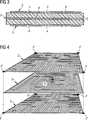
Eine besonders gute Dämpfungswirkung wird in der Schirmung dadurch erreicht, dass auf beiden Seiten des zumindest einen Substrats eine jeweilige Metallstruktur angeordnet ist. Hierdurch ergibt sich mittels des Substrats für in Draufsicht auf das Substrat überlappende Teilbereiche eine kapazitive Kopplung. Die Dämpfungswirkung kann ferner dadurch verbessert werden, dass die Schirmung eine Mehrzahl von übereinander liegenden Substraten umfasst, wobei zwischen benachbarten Seiten von zumindest einem Paar und insbesondere von allen Paaren von benachbarten Substraten eine jeweilige Metallstruktur angeordnet ist. Vorzugsweise ist auch auf der Oberseite des obersten Substrats und/oder auf der Unterseite des untersten Substrats der Mehrzahl von übereinander liegenden Substraten eine jeweilige Metallstruktur angeordnet.A particularly good damping effect is achieved in the shield by arranging a respective metal structure on both sides of the at least one substrate. This results in a capacitive coupling by means of the substrate for overlapping in plan view of the substrate portions. The damping effect can be further improved by the shield comprising a plurality of superimposed substrates, wherein a respective metal structure is arranged between adjacent sides of at least one pair and in particular of all pairs of adjacent substrates. Preferably, a respective metal structure is also arranged on the upper side of the uppermost substrate and / or on the underside of the lowermost substrate of the plurality of superimposed substrates.
In einer weiteren Ausgestaltung der Erfindung sind zwei benachbarte Metallstrukturen, welche über ein Substrat voneinander getrennt sind, derart ausgestaltet, dass die Teilbereiche der benachbarten Metallstrukturen in Draufsicht auf die Ebene des Substrats zueinander versetzt sind. Hierdurch kann die kapazitive Kopplung zwischen Teilbereichen benachbarter Metallstrukturen erhöht werden.In a further embodiment of the invention, two adjacent metal structures, which are separated from each other by a substrate, are configured such that the subregions of the adjacent metal structures are offset from one another in a plan view of the plane of the substrate. As a result, the capacitive coupling between portions of adjacent metal structures can be increased.
In einer Ausgestaltung der Erfindung ist die Metallstruktur mit einer Masse einer elektrischen oder elektronischen Schaltung, in welche die erste Spule eingebunden ist, verbunden.In one embodiment of the invention, the metal structure is connected to a mass of an electrical or electronic circuit, in which the first coil is incorporated.
In einer weiteren Ausführungsform ist die Schirmung derart angeordnet, dass sie die erste Spule zumindest teilweise verdeckt und damit abschirmt.In a further embodiment, the shielding is arranged such that it at least partially obscures and thus shields the first coil.
Ausführungsbeispiele der Erfindung werden nachfolgend anhand der beigefügten Figuren detailliert beschriebenEmbodiments of the invention are described below in detail with reference to the accompanying drawings
Es zeigen:Show it:
Durch die Verwendung der frequenzselektiven Schirmung
Damit der Ferrit sowohl in der Primär- als auch in der Sekundärspule für höhere Frequenzen im MHz-GHz-Bereich abgeschirmt werden kann, muss eine Schirmung aus Metall oder einem mit Metall beschichteten Material verwendet werden. Eine solche Schirmplatte führt zu Problemen in der Übertragung des niederfrequenten Signals, da in der Platte Wirbelströme induziert würden, welche auch zu einem Aufheizen der Platte und hohen Leistungsverlusten führen.In order for the ferrite to be shielded in both the primary and secondary coils for higher frequencies in the MHz GHz range, a shield of metal or a metal coated material must be used. Such a screen plate leads to problems in the transmission of the low-frequency signal, since eddy currents would be induced in the plate, which also lead to a heating of the plate and high power losses.
Die frequenzselektive Schirmung
In der Ausführungsform der
Wie man aus
Die einzelnen Metallstrukturen
Die im Vorangegangenen beschriebenen Ausführungsformen der Schirmung weisen eine Reihe von Vorteilen auf. Insbesondere wird durch die spezielle fraktale Strukturierung der Metallstruktur eine Schirmwirkung bis in den unteren MHz-Frequenzbereich erreicht, ohne dass zusätzlich kapazitive Bauteile vorgesehen werden müssen. Gleichzeitig wird gewährleistet, dass die metallische Struktur für niedrige Frequenzen transparent ist, wodurch Wirbelströme in der Metallstruktur vermieden werden. Durch einen mehrschichtigen Aufbau der Schirmung kann diese für unterschiedliche Einsatzbereiche flexibel angepasst werden. Ferner wird hierdurch die Schirmwirkung für hochfrequente Frequenzanteile verbessert.The embodiments of the shield described above have a number of advantages. In particular, the special fractal structuring of the metal structure achieves a shielding effect down to the lower MHz frequency range, without having to additionally provide capacitive components. At the same time, it ensures that the metallic structure is transparent to low frequencies, thereby avoiding eddy currents in the metal structure. Due to the multi-layer structure of the shielding, it can be flexibly adapted for different areas of application. Furthermore, this improves the shielding effect for high frequency frequency components.
Aus dem Stand der Technik sind weitere Ausführungsbeispiele für die Ausgestaltung der Schirmung bekannt, welche anstelle der zuvor beschriebenen Ausführungsbeispiele verwendet werden können.From the prior art further embodiments of the design of the shielding are known, which can be used in place of the embodiments described above.
So zeigt die Druckschrift
Aus der
Das Detektionsmittel
Obwohl die Erfindung im Detail durch die Ausführungsbeispiele näher illustriert und beschrieben wurde, ist die Erfindung nicht durch die offenbarten Beispiele eingeschränkt und andere Variationen können vom Fachmann hieraus abgeleitet werden, ohne den Schutzumfang der Erfindung zu verlassen. Die beschriebenen Ausführungsbeispiele, Varianten, Ausführungsformen und Weiterbildungen können ferner frei miteinander kombiniert werden.Although the invention has been further illustrated and described in detail by the embodiments, the invention is not limited by the disclosed examples, and other variations can be derived therefrom by those skilled in the art without departing from the scope of the invention. The described embodiments, variants, embodiments and developments can also be freely combined with each other.
ZITATE ENTHALTEN IN DER BESCHREIBUNG QUOTES INCLUDE IN THE DESCRIPTION
Diese Liste der vom Anmelder aufgeführten Dokumente wurde automatisiert erzeugt und ist ausschließlich zur besseren Information des Lesers aufgenommen. Die Liste ist nicht Bestandteil der deutschen Patent- bzw. Gebrauchsmusteranmeldung. Das DPMA übernimmt keinerlei Haftung für etwaige Fehler oder Auslassungen.This list of the documents listed by the applicant has been generated automatically and is included solely for the better information of the reader. The list is not part of the German patent or utility model application. The DPMA assumes no liability for any errors or omissions.
Zitierte PatentliteraturCited patent literature
- DE 202009009689 U1[0003]DE 202009009689 U1[0003]
- WO 2009081115 A1[0004]WO 2009081115 A1[0004]
- US 2011/0074346 A1[0005]US 2011/0074346 A1[0005]
- WO 2008/051915 A1[0051]WO 2008/051915 A1[0051]
- DE 102011084071 A1[0052]DE 102011084071 A1[0052]
Claims (20)
Translated fromGermanPriority Applications (2)
| Application Number | Priority Date | Filing Date | Title |
|---|---|---|---|
| DE201310221659DE102013221659A1 (en) | 2013-10-24 | 2013-10-24 | Arrangement for providing an inductive charging connection |
| PCT/EP2014/069070WO2015058895A1 (en) | 2013-10-24 | 2014-09-08 | Arrangement for providing an inductive charging connection |
Applications Claiming Priority (1)
| Application Number | Priority Date | Filing Date | Title |
|---|---|---|---|
| DE201310221659DE102013221659A1 (en) | 2013-10-24 | 2013-10-24 | Arrangement for providing an inductive charging connection |
Publications (1)
| Publication Number | Publication Date |
|---|---|
| DE102013221659A1true DE102013221659A1 (en) | 2015-04-30 |
Family
ID=51570477
Family Applications (1)
| Application Number | Title | Priority Date | Filing Date |
|---|---|---|---|
| DE201310221659CeasedDE102013221659A1 (en) | 2013-10-24 | 2013-10-24 | Arrangement for providing an inductive charging connection |
Country Status (2)
| Country | Link |
|---|---|
| DE (1) | DE102013221659A1 (en) |
| WO (1) | WO2015058895A1 (en) |
Cited By (1)
| Publication number | Priority date | Publication date | Assignee | Title |
|---|---|---|---|---|
| WO2017048505A1 (en)* | 2015-09-17 | 2017-03-23 | Qualcomm Incorporated | Wireless power transfer antenna having a split shield |
Citations (7)
| Publication number | Priority date | Publication date | Assignee | Title |
|---|---|---|---|---|
| WO2008051915A1 (en) | 2006-10-26 | 2008-05-02 | Cherik Bulkes | Mri compatible implanted electronic medical device with power and data communication capability |
| WO2009081115A1 (en) | 2007-12-21 | 2009-07-02 | Amway (Europe) Limited | Inductive power transfer |
| US7737899B1 (en)* | 2006-07-13 | 2010-06-15 | Wemtec, Inc. | Electrically-thin bandpass radome with isolated inductive grids |
| DE202009009689U1 (en) | 2009-07-14 | 2010-11-25 | Conductix-Wampfler Ag | Device for inductive transmission of electrical energy |
| US20110074346A1 (en) | 2009-09-25 | 2011-03-31 | Hall Katherine L | Vehicle charger safety system and method |
| JP2012249490A (en)* | 2011-05-31 | 2012-12-13 | Kojima Press Industry Co Ltd | Vehicle-mounted charger and vehicle-mounted power supply device |
| DE102011084071A1 (en) | 2011-10-06 | 2013-04-11 | Siemens Aktiengesellschaft | Shield for electronic circuit |
Family Cites Families (2)
| Publication number | Priority date | Publication date | Assignee | Title |
|---|---|---|---|---|
| DE102007023343A1 (en)* | 2006-05-30 | 2007-12-06 | Sew-Eurodrive Gmbh & Co. Kg | Transmitter head for contactless energy transmission system, has condensers and winding arranged in inner side of housing and separated by ferrite parts, where condensers and secondary coil are arranged in same or overlapping axial areas |
| TWM320264U (en)* | 2006-12-08 | 2007-10-01 | P Two Ind Inc | Multi-band frequency-selective filter |
- 2013
- 2013-10-24DEDE201310221659patent/DE102013221659A1/ennot_activeCeased
- 2014
- 2014-09-08WOPCT/EP2014/069070patent/WO2015058895A1/enactiveApplication Filing
Patent Citations (7)
| Publication number | Priority date | Publication date | Assignee | Title |
|---|---|---|---|---|
| US7737899B1 (en)* | 2006-07-13 | 2010-06-15 | Wemtec, Inc. | Electrically-thin bandpass radome with isolated inductive grids |
| WO2008051915A1 (en) | 2006-10-26 | 2008-05-02 | Cherik Bulkes | Mri compatible implanted electronic medical device with power and data communication capability |
| WO2009081115A1 (en) | 2007-12-21 | 2009-07-02 | Amway (Europe) Limited | Inductive power transfer |
| DE202009009689U1 (en) | 2009-07-14 | 2010-11-25 | Conductix-Wampfler Ag | Device for inductive transmission of electrical energy |
| US20110074346A1 (en) | 2009-09-25 | 2011-03-31 | Hall Katherine L | Vehicle charger safety system and method |
| JP2012249490A (en)* | 2011-05-31 | 2012-12-13 | Kojima Press Industry Co Ltd | Vehicle-mounted charger and vehicle-mounted power supply device |
| DE102011084071A1 (en) | 2011-10-06 | 2013-04-11 | Siemens Aktiengesellschaft | Shield for electronic circuit |
Cited By (1)
| Publication number | Priority date | Publication date | Assignee | Title |
|---|---|---|---|---|
| WO2017048505A1 (en)* | 2015-09-17 | 2017-03-23 | Qualcomm Incorporated | Wireless power transfer antenna having a split shield |
Also Published As
| Publication number | Publication date |
|---|---|
| WO2015058895A1 (en) | 2015-04-30 |
Similar Documents
| Publication | Publication Date | Title |
|---|---|---|
| EP3602785B1 (en) | Door handle assembly for a motor vehicle having a capacitive sensor and near-field communication | |
| DE102009055342B4 (en) | circuit board | |
| DE102014207885A1 (en) | Foreign object detection device and power inductive charging device | |
| DE102011078077A1 (en) | Printed circuit board with electrode configuration of a capacitive sensor | |
| DE102008012922B4 (en) | Inductive angle sensor | |
| EP3664046B1 (en) | Vehicle door handle with sensor device and wireless communication device | |
| DE102012206549B4 (en) | Shield for an electronic circuit | |
| DE69029757T2 (en) | LC noise filter | |
| DE102011109553A1 (en) | Sensor and sensor element | |
| EP3245480B1 (en) | Inductive position determination | |
| WO2011044965A1 (en) | Antenna coupler | |
| DE102011084071A1 (en) | Shield for electronic circuit | |
| DE102006022160B3 (en) | Test device with HF / UHF dual band antenna for testing RFID transponders in a production device | |
| DE102013221659A1 (en) | Arrangement for providing an inductive charging connection | |
| DE202012007631U1 (en) | Electronic locking device | |
| DE102016204016A1 (en) | Tilt-tolerant displacement sensor | |
| EP2130000B1 (en) | Rotation angle sensor or length sensor | |
| DE102014207890A1 (en) | Foreign object detection device and power inductive charging device | |
| DE102019116322B4 (en) | Imaging apparatus, method of designing a circuit board assembly and circuit board assembly | |
| DE102012217760A1 (en) | Decoupling of split-ring resonators in magnetic resonance imaging | |
| DE102021132393A1 (en) | sensor arrangement; Steering; Vehicle, method for position measurement using a sensor array | |
| DE102021132396A1 (en) | sensor arrangement; Steering; Vehicle, method for position measurement using a sensor array | |
| DE102011090139A1 (en) | Transmission arrangement for a radio station and radio station | |
| DE102008051531B4 (en) | Electrical system with a device for suppressing the propagation of electromagnetic interference | |
| DE102005013293A1 (en) | Magnetic resonance system has barrier that shields high frequency sources from electric field by being arranged between high frequency sources and diagnosis chamber |
Legal Events
| Date | Code | Title | Description |
|---|---|---|---|
| R012 | Request for examination validly filed | ||
| R079 | Amendment of ipc main class | Free format text:PREVIOUS MAIN CLASS: H02J0007000000 Ipc:H02J0017000000 | |
| R079 | Amendment of ipc main class | Free format text:PREVIOUS MAIN CLASS: H02J0017000000 Ipc:H02J0050100000 | |
| R002 | Refusal decision in examination/registration proceedings | ||
| R003 | Refusal decision now final |