DE102013218441A1 - Direct plug-in device with Vorjustiereinrichtung and relative to this sliding locking device - Google Patents
Direct plug-in device with Vorjustiereinrichtung and relative to this sliding locking deviceDownload PDFInfo
- Publication number
- DE102013218441A1 DE102013218441A1DE102013218441.7ADE102013218441ADE102013218441A1DE 102013218441 A1DE102013218441 A1DE 102013218441A1DE 102013218441 ADE102013218441 ADE 102013218441ADE 102013218441 A1DE102013218441 A1DE 102013218441A1
- Authority
- DE
- Germany
- Prior art keywords
- plug
- circuit board
- printed circuit
- direct
- plug element
- Prior art date
- Legal status (The legal status is an assumption and is not a legal conclusion. Google has not performed a legal analysis and makes no representation as to the accuracy of the status listed.)
- Withdrawn
Links
- 238000000034methodMethods0.000claimsdescription17
- 238000003780insertionMethods0.000claimsdescription14
- 230000037431insertionEffects0.000claimsdescription14
- 239000012777electrically insulating materialSubstances0.000claimsdescription2
- 239000000463materialSubstances0.000claimsdescription2
- 230000000875corresponding effectEffects0.000description16
- 238000006073displacement reactionMethods0.000description3
- 230000009471actionEffects0.000description2
- 230000000694effectsEffects0.000description2
- 238000001746injection mouldingMethods0.000description2
- 230000013011matingEffects0.000description2
- 230000007246mechanismEffects0.000description2
- 239000002184metalSubstances0.000description2
- 230000001681protective effectEffects0.000description2
- BUHVIAUBTBOHAG-FOYDDCNASA-N(2r,3r,4s,5r)-2-[6-[[2-(3,5-dimethoxyphenyl)-2-(2-methylphenyl)ethyl]amino]purin-9-yl]-5-(hydroxymethyl)oxolane-3,4-diolChemical compoundCOC1=CC(OC)=CC(C(CNC=2C=3N=CN(C=3N=CN=2)[C@H]2[C@@H]([C@H](O)[C@@H](CO)O2)O)C=2C(=CC=CC=2)C)=C1BUHVIAUBTBOHAG-FOYDDCNASA-N0.000description1
- 230000008878couplingEffects0.000description1
- 238000010168coupling processMethods0.000description1
- 238000005859coupling reactionMethods0.000description1
- 230000001419dependent effectEffects0.000description1
- 230000001066destructive effectEffects0.000description1
- 238000011161developmentMethods0.000description1
- 230000018109developmental processEffects0.000description1
- 230000002996emotional effectEffects0.000description1
- 238000009434installationMethods0.000description1
- 230000003993interactionEffects0.000description1
- 238000004519manufacturing processMethods0.000description1
- 230000002093peripheral effectEffects0.000description1
- 230000008569processEffects0.000description1
- 239000012858resilient materialSubstances0.000description1
- 230000002441reversible effectEffects0.000description1
- 230000007480spreadingEffects0.000description1
- 239000006228supernatantSubstances0.000description1
- 230000002195synergetic effectEffects0.000description1
- 230000001960triggered effectEffects0.000description1
Images


Classifications
- H—ELECTRICITY
- H01—ELECTRIC ELEMENTS
- H01R—ELECTRICALLY-CONDUCTIVE CONNECTIONS; STRUCTURAL ASSOCIATIONS OF A PLURALITY OF MUTUALLY-INSULATED ELECTRICAL CONNECTING ELEMENTS; COUPLING DEVICES; CURRENT COLLECTORS
- H01R12/00—Structural associations of a plurality of mutually-insulated electrical connecting elements, specially adapted for printed circuits, e.g. printed circuit boards [PCB], flat or ribbon cables, or like generally planar structures, e.g. terminal strips, terminal blocks; Coupling devices specially adapted for printed circuits, flat or ribbon cables, or like generally planar structures; Terminals specially adapted for contact with, or insertion into, printed circuits, flat or ribbon cables, or like generally planar structures
- H01R12/70—Coupling devices
- H01R12/71—Coupling devices for rigid printing circuits or like structures
- H01R12/712—Coupling devices for rigid printing circuits or like structures co-operating with the surface of the printed circuit or with a coupling device exclusively provided on the surface of the printed circuit
- H01R12/714—Coupling devices for rigid printing circuits or like structures co-operating with the surface of the printed circuit or with a coupling device exclusively provided on the surface of the printed circuit with contacts abutting directly the printed circuit; Button contacts therefore provided on the printed circuit
- H—ELECTRICITY
- H01—ELECTRIC ELEMENTS
- H01R—ELECTRICALLY-CONDUCTIVE CONNECTIONS; STRUCTURAL ASSOCIATIONS OF A PLURALITY OF MUTUALLY-INSULATED ELECTRICAL CONNECTING ELEMENTS; COUPLING DEVICES; CURRENT COLLECTORS
- H01R12/00—Structural associations of a plurality of mutually-insulated electrical connecting elements, specially adapted for printed circuits, e.g. printed circuit boards [PCB], flat or ribbon cables, or like generally planar structures, e.g. terminal strips, terminal blocks; Coupling devices specially adapted for printed circuits, flat or ribbon cables, or like generally planar structures; Terminals specially adapted for contact with, or insertion into, printed circuits, flat or ribbon cables, or like generally planar structures
- H01R12/50—Fixed connections
- H01R12/51—Fixed connections for rigid printed circuits or like structures
- H01R12/515—Terminal blocks providing connections to wires or cables
- H—ELECTRICITY
- H01—ELECTRIC ELEMENTS
- H01R—ELECTRICALLY-CONDUCTIVE CONNECTIONS; STRUCTURAL ASSOCIATIONS OF A PLURALITY OF MUTUALLY-INSULATED ELECTRICAL CONNECTING ELEMENTS; COUPLING DEVICES; CURRENT COLLECTORS
- H01R12/00—Structural associations of a plurality of mutually-insulated electrical connecting elements, specially adapted for printed circuits, e.g. printed circuit boards [PCB], flat or ribbon cables, or like generally planar structures, e.g. terminal strips, terminal blocks; Coupling devices specially adapted for printed circuits, flat or ribbon cables, or like generally planar structures; Terminals specially adapted for contact with, or insertion into, printed circuits, flat or ribbon cables, or like generally planar structures
- H01R12/50—Fixed connections
- H01R12/51—Fixed connections for rigid printed circuits or like structures
- H01R12/55—Fixed connections for rigid printed circuits or like structures characterised by the terminals
- H01R12/58—Fixed connections for rigid printed circuits or like structures characterised by the terminals terminals for insertion into holes
- H01R12/585—Terminals having a press fit or a compliant portion and a shank passing through a hole in the printed circuit board
- H—ELECTRICITY
- H01—ELECTRIC ELEMENTS
- H01R—ELECTRICALLY-CONDUCTIVE CONNECTIONS; STRUCTURAL ASSOCIATIONS OF A PLURALITY OF MUTUALLY-INSULATED ELECTRICAL CONNECTING ELEMENTS; COUPLING DEVICES; CURRENT COLLECTORS
- H01R12/00—Structural associations of a plurality of mutually-insulated electrical connecting elements, specially adapted for printed circuits, e.g. printed circuit boards [PCB], flat or ribbon cables, or like generally planar structures, e.g. terminal strips, terminal blocks; Coupling devices specially adapted for printed circuits, flat or ribbon cables, or like generally planar structures; Terminals specially adapted for contact with, or insertion into, printed circuits, flat or ribbon cables, or like generally planar structures
- H01R12/70—Coupling devices
- H01R12/7005—Guiding, mounting, polarizing or locking means; Extractors
- H01R12/7011—Locking or fixing a connector to a PCB
- H01R12/7052—Locking or fixing a connector to a PCB characterised by the locating members
- H—ELECTRICITY
- H01—ELECTRIC ELEMENTS
- H01R—ELECTRICALLY-CONDUCTIVE CONNECTIONS; STRUCTURAL ASSOCIATIONS OF A PLURALITY OF MUTUALLY-INSULATED ELECTRICAL CONNECTING ELEMENTS; COUPLING DEVICES; CURRENT COLLECTORS
- H01R12/00—Structural associations of a plurality of mutually-insulated electrical connecting elements, specially adapted for printed circuits, e.g. printed circuit boards [PCB], flat or ribbon cables, or like generally planar structures, e.g. terminal strips, terminal blocks; Coupling devices specially adapted for printed circuits, flat or ribbon cables, or like generally planar structures; Terminals specially adapted for contact with, or insertion into, printed circuits, flat or ribbon cables, or like generally planar structures
- H01R12/70—Coupling devices
- H01R12/7005—Guiding, mounting, polarizing or locking means; Extractors
- H01R12/7011—Locking or fixing a connector to a PCB
- H01R12/7058—Locking or fixing a connector to a PCB characterised by the movement, e.g. pivoting, camming or translating parallel to the PCB
- H—ELECTRICITY
- H01—ELECTRIC ELEMENTS
- H01R—ELECTRICALLY-CONDUCTIVE CONNECTIONS; STRUCTURAL ASSOCIATIONS OF A PLURALITY OF MUTUALLY-INSULATED ELECTRICAL CONNECTING ELEMENTS; COUPLING DEVICES; CURRENT COLLECTORS
- H01R12/00—Structural associations of a plurality of mutually-insulated electrical connecting elements, specially adapted for printed circuits, e.g. printed circuit boards [PCB], flat or ribbon cables, or like generally planar structures, e.g. terminal strips, terminal blocks; Coupling devices specially adapted for printed circuits, flat or ribbon cables, or like generally planar structures; Terminals specially adapted for contact with, or insertion into, printed circuits, flat or ribbon cables, or like generally planar structures
- H01R12/70—Coupling devices
- H01R12/7005—Guiding, mounting, polarizing or locking means; Extractors
- H01R12/7011—Locking or fixing a connector to a PCB
- H01R12/7064—Press fitting
- H—ELECTRICITY
- H01—ELECTRIC ELEMENTS
- H01R—ELECTRICALLY-CONDUCTIVE CONNECTIONS; STRUCTURAL ASSOCIATIONS OF A PLURALITY OF MUTUALLY-INSULATED ELECTRICAL CONNECTING ELEMENTS; COUPLING DEVICES; CURRENT COLLECTORS
- H01R12/00—Structural associations of a plurality of mutually-insulated electrical connecting elements, specially adapted for printed circuits, e.g. printed circuit boards [PCB], flat or ribbon cables, or like generally planar structures, e.g. terminal strips, terminal blocks; Coupling devices specially adapted for printed circuits, flat or ribbon cables, or like generally planar structures; Terminals specially adapted for contact with, or insertion into, printed circuits, flat or ribbon cables, or like generally planar structures
- H01R12/70—Coupling devices
- H01R12/7082—Coupling device supported only by cooperation with PCB
- H—ELECTRICITY
- H01—ELECTRIC ELEMENTS
- H01R—ELECTRICALLY-CONDUCTIVE CONNECTIONS; STRUCTURAL ASSOCIATIONS OF A PLURALITY OF MUTUALLY-INSULATED ELECTRICAL CONNECTING ELEMENTS; COUPLING DEVICES; CURRENT COLLECTORS
- H01R13/00—Details of coupling devices of the kinds covered by groups H01R12/70 or H01R24/00 - H01R33/00
- H01R13/46—Bases; Cases
- H01R13/502—Bases; Cases composed of different pieces
- H—ELECTRICITY
- H01—ELECTRIC ELEMENTS
- H01R—ELECTRICALLY-CONDUCTIVE CONNECTIONS; STRUCTURAL ASSOCIATIONS OF A PLURALITY OF MUTUALLY-INSULATED ELECTRICAL CONNECTING ELEMENTS; COUPLING DEVICES; CURRENT COLLECTORS
- H01R13/00—Details of coupling devices of the kinds covered by groups H01R12/70 or H01R24/00 - H01R33/00
- H01R13/62—Means for facilitating engagement or disengagement of coupling parts or for holding them in engagement
- H01R13/627—Snap or like fastening
- H01R13/6271—Latching means integral with the housing
- H—ELECTRICITY
- H01—ELECTRIC ELEMENTS
- H01R—ELECTRICALLY-CONDUCTIVE CONNECTIONS; STRUCTURAL ASSOCIATIONS OF A PLURALITY OF MUTUALLY-INSULATED ELECTRICAL CONNECTING ELEMENTS; COUPLING DEVICES; CURRENT COLLECTORS
- H01R13/00—Details of coupling devices of the kinds covered by groups H01R12/70 or H01R24/00 - H01R33/00
- H01R13/62—Means for facilitating engagement or disengagement of coupling parts or for holding them in engagement
- H01R13/629—Additional means for facilitating engagement or disengagement of coupling parts, e.g. aligning or guiding means, levers, gas pressure electrical locking indicators, manufacturing tolerances
- H—ELECTRICITY
- H01—ELECTRIC ELEMENTS
- H01R—ELECTRICALLY-CONDUCTIVE CONNECTIONS; STRUCTURAL ASSOCIATIONS OF A PLURALITY OF MUTUALLY-INSULATED ELECTRICAL CONNECTING ELEMENTS; COUPLING DEVICES; CURRENT COLLECTORS
- H01R13/00—Details of coupling devices of the kinds covered by groups H01R12/70 or H01R24/00 - H01R33/00
- H01R13/62—Means for facilitating engagement or disengagement of coupling parts or for holding them in engagement
- H01R13/639—Additional means for holding or locking coupling parts together, after engagement, e.g. separate keylock, retainer strap
- H01R13/6395—Additional means for holding or locking coupling parts together, after engagement, e.g. separate keylock, retainer strap for wall or panel outlets
Landscapes
- Coupling Device And Connection With Printed Circuit (AREA)
- Details Of Connecting Devices For Male And Female Coupling (AREA)
Abstract
Translated fromGermanDescription
Translated fromGermanDie Erfindung betrifft eine Direktsteckvorrichtung zum direkten Stecken auf eine Leiterplatte.The invention relates to a direct plug-in device for direct plugging onto a printed circuit board.
Es ist eine Anordnung zum elektrischen und mechanischen Verbinden von Steckelementen über einen Sockel mit einer Leiterplatte bekannt, die für hohe elektrische und mechanische Anforderungen ausgelegt ist.It is known an arrangement for the electrical and mechanical connection of plug-in elements via a socket with a printed circuit board, which is designed for high electrical and mechanical requirements.
Es sind auch Verbindungsanordnungen für Leiterplatten bekannt, die ein direktes Aufstecken eines Steckteils auf eine Leiterplatte ohne an der Leiterplatte befestigte Buchse ermöglicht.There are also known connection arrangements for printed circuit boards, which allows a direct insertion of a male part on a circuit board without attached to the circuit board socket.
Obwohl eine solche eine Verbindungsanordnung viele Vorteile aufweist, kann der Umgang mit den relativ empfindlichen Kontaktelementen sowie dessen korrekte Positionierung an der Leiterplatte für einen Benutzer herausfordernd sein.Although such a connector assembly has many advantages, dealing with the relatively sensitive contact elements as well as its correct positioning on the circuit board can be challenging for a user.
Der Erfindung liegt die Aufgabe zu Grunde, eine Direktsteckvorrichtung zum direkten Stecken auf eine Leiterplatte zu schaffen, die robust und für einen Benutzer einfach handhabbar ist.The invention is based on the object to provide a direct plug-in device for direct plugging onto a printed circuit board, which is robust and easy to handle for a user.
Zur Lösung dieser Aufgabe schlägt die Erfindung eine Direktsteckvorrichtung, eine Verbindungsanordnung und ein Verfahren mit den in den unabhängigen Ansprüchen genannten Merkmalen vor. Weiterbildungen der Erfindung sind Gegenstand von Unteransprüchen.To achieve this object, the invention proposes a direct plug-in device, a connection arrangement and a method with the features mentioned in the independent claims. Further developments of the invention are the subject of dependent claims.
Gemäß einem Ausführungsbeispiel der Erfindung ist eine Direktsteckvorrichtung zum direkten Stecken auf eine Leiterplatte geschaffen, wobei die Direktsteckvorrichtung ein Steckelement, das ein (insbesondere elektrisch isolierendes) Aufnahmegehäuse und mindestens ein (insbesondere elektrisch leitfähiges) daran aufgenommenes steckbares (insbesondere federartiges) Kontaktelement (insbesondere eine Mehrzahl solcher Kontaktelemente, wobei ein Kontaktelement auch als Direktsteckkontakt bezeichnet werden kann) aufweist, und eine Steckelementaufnahme (die insbesondere als Verriegelungsrahmen ausgebildet sein kann) aufweist, die zum zumindest teilweisen (insbesondere seitlich-umfänglichen) Aufnehmen des Steckelements eingerichtet ist, eine Verriegelungseinrichtung aufweist und relativ zu dem Steckelement zwischen einem kontaktelementfernen Zustand und einem kontaktelementnahen Zustand (wobei in dem kontaktelementfernen Zustand ein Abstand zwischen der Steckelementaufnahme und dem mindestens einen Kontaktelement größer ist als in dem kontaktelementnahen Zustand) verfahrbar (insbesondere längsverschiebbar) ist, wobei das Steckelement mindestens eine leiterplattenseitig anzuordnende Vorjustierstruktur aufweist, die mittels Aufsetzens des Steckelements auf die Leiterplatte mit mindestens einer korrespondierenden Vorjustierstruktur der Leiterplatte derart verbindbar ist, dass im verbundenen Zustand das mindestens eine Kontaktelement zu mindestens einer korrespondierend ausgebildeten Kontaktelementöffnung (insbesondere ein Kontaktelementdurchgangsloch) der Leiterplatte ausgerichtet ist, und wobei die Steckelementaufnahme gegenüber dem auf die Leiterplatte vorjustiert aufgesetzten Steckelement derart von dem kontaktelementfernen Zustand zu dem kontaktelementnahen Zustand verfahrbar ist, dass dadurch die Verriegelungseinrichtung und die Vorjustierstruktur des Steckelements gemeinsam (bzw. zusammenwirkend) an der Vorjustierstruktur der Leiterplatte verriegelt werden.According to one exemplary embodiment of the invention, a direct plug-in device is provided for direct plugging onto a printed circuit board, wherein the direct plug-in device has a plug-in element which has a (in particular electrically insulating) receptacle housing and at least one (in particular electrically conductive) pluggable (in particular spring-like) contact element (in particular a plurality Such contact elements, wherein a contact element can also be referred to as a direct plug contact), and a plug element receptacle (which may be formed in particular as a locking frame), which is arranged for at least partially (in particular laterally-circumferential) receiving the plug element, has a locking device and relative to the male element between a contact element remote state and a contact element near state (wherein in the contact element remote state, a distance between the plug element receptacle and the least s a contact element is greater than in the contact element near state) movable (in particular longitudinally displaceable), wherein the plug element has at least one Vorwerkierseitig to be arranged on the printed circuit board side, by means of placing the plug element on the circuit board with at least one corresponding Vorjustierstruktur the circuit board is connected such that in the connected Condition, the at least one contact element to at least one correspondingly formed contact element opening (in particular a contact element through hole) of the printed circuit board is aligned, and wherein the plug receptacle relative to the pre-aligned on the printed circuit board plug-in element is movable from the contact element remote state to the contact element near state that thereby the locking device and the Vorjustierstruktur the male element together (or cooperatively) are locked to the Vorjustierstruktur the circuit board.
Gemäß einem anderen Ausführungsbeispiel der Erfindung ist eine Verbindungsanordnung bereitgestellt, die eine Leiterplatte, die mindestens eine Vorjustierstruktur und mindestens eine Kontaktelementöffnung aufweist, und eine Direktsteckvorrichtung mit den oben beschriebenen Merkmalen aufweist, die zum direkten Stecken auf die Leiterplatte mittels Verbindens der mindestens einen Vorjustierstruktur des Steckelements mit der mindestens einen korrespondierenden Vorjustierstruktur der Leiterplatte und mittels nachfolgenden Verfahrens der Steckelementaufnahme gegenüber dem Steckelement und der Leiterplatte von dem kontaktelementfernen Zustand zu dem kontaktelementnahen Zustand derart ausgebildet ist, dass dadurch die Verriegelungseinrichtung und die Vorjustierstruktur des Steckelements gemeinsam an der Vorjustierstruktur der Leiterplatte verriegelt werden.According to another embodiment of the invention, there is provided a connection assembly comprising a printed circuit board having at least one pre-alignment structure and at least one contact element opening and a direct plug device having the features described above for directly plugging onto the circuit board by connecting the at least one pre-alignment structure of the plug element with the at least one corresponding Vorjustierstruktur the circuit board and by subsequent method of the plug element receptacle relative to the plug element and the circuit board from the contact element remote state to the contact element near state is formed such that thereby the locking device and Vorjustierstruktur the plug element are locked together on the Vorjustierstruktur the circuit board.
Gemäß einem weiteren Ausführungsbeispiel der Erfindung ist ein Verfahren zum direkten Stecken einer Direktsteckvorrichtung auf eine Leiterplatte bereitgestellt, wobei bei dem Verfahren ein Steckelement bereitgestellt wird, das ein Aufnahmegehäuse und mindestens ein daran aufgenommenes steckbares, insbesondere federartiges, Kontaktelement aufweist, das Steckelements zumindest teilweise durch eine Steckelementaufnahme aufgenommen wird, die eine Verriegelungseinrichtung aufweist und relativ zu dem Steckelement zwischen einem kontaktelementfernen Zustand und einem kontaktelementnahen Zustand verfahrbar ist, das Steckelement auf die Leiterplatte aufgesetzt wird, wodurch mindestens eine leiterplattenseitige Vorjustierstruktur des Steckelements mit mindestens einer korrespondierenden Vorjustierstruktur der Leiterplatte derart verbunden wird, dass durch das Verbinden das mindestens eine Kontaktelement zu mindestens einer korrespondierend ausgebildeten Kontaktelementöffnung der Leiterplatte ausgerichtet wird (und vorzugsweise dadurch simultan ein elektrisch leitfähiger Kontakt zwischen dem mindestens einen Kontaktelement und der zugehörigen mindestens einen Kontaktelementöffnung ausgebildet wird), und die Steckelementaufnahme gegenüber dem auf die Leiterplatte vorjustiert aufgesetzten Steckelement derart von dem kontaktelementfernen Zustand zu dem kontaktelementnahen Zustand verfahren wird, dass dadurch die Verriegelungseinrichtung und die Vorjustierstruktur des Steckelements gemeinsam an der Vorjustierstruktur der Leiterplatte verriegelt werden. According to a further exemplary embodiment of the invention, a method is provided for directly plugging a direct plug device onto a printed circuit board, wherein in the method a plug element is provided which has a receptacle housing and at least one plug-in, in particular spring-like, contact element received thereon, at least partially by a plug element Plug element receptacle is received, which has a locking device and is movable relative to the plug element between a contact element remote state and a contact element near state, the plug element is placed on the circuit board, whereby at least one pcb side Vorjustierstruktur the plug element is connected to at least one corresponding Vorjustierstruktur the circuit board such in that by connecting the at least one contact element to at least one correspondingly formed contact element opening of the printed circuit board e is aligned (and preferably thereby simultaneously an electrically conductive contact between the at least one contact element and the associated at least one contact element opening is formed), and the plug receptacle is moved relative to the pre-aligned on the circuit board plug-in element from the contact element remote state to the contact element near state, in that thereby the locking device and the Vorjustierstruktur of the plug element are locked together on the Vorjustierstruktur the circuit board.
Gemäß einem exemplarischen Ausführungsbeispiel ist ein von Hand steckbares und von Hand lösbares System geschaffen, mit dem eine fehlerrobuste elektrische Kontaktierung zwischen mindestens einem empfindlichen Kontaktelement einerseits und einer Leiterplatte andererseits dadurch ermöglicht wird, dass zunächst mindestens eine Vorjustierstruktur an einem Steckelement mit dem mindestens einen Kontaktelement auf mindestens eine korrespondierende Vorjustierstruktur der Leiterplatte aufgesetzt wird. Das mindestens eine Kontaktelement kann bei diesem Vorjustiervorgang bereits in die mindestens eine korrespondierende Kontaktelementöffnung der Leiterplatte eintauchen und hierbei vorzugsweise bereits einen elektrisch leitfähigen Kontakt herstellen. Dadurch wird ein mechanisch korrektes Anbringen der Direktsteckvorrichtung an der Leiterplatte sichergestellt und vorzugsweise bereits die elektrische Kontaktierung bewerkstelligt. Der beschriebene Vorjustiervorgang ist mit sehr geringem Kraftaufwand möglich, da durch das Vorjustieren noch keine Verriegelungsbefestigung der Direktsteckvorrichtung an der Leiterplatte einhergeht. Durch ein bloßes Überführen einer außenseitigen Steckelementaufnahme von einem kontaktelementfernen bzw. leiterplattenfernen Zustand in einen kontaktelemennahen bzw. leiterplattennahen Zustand, d.h. durch Verschieben der Steckelementaufnahme in Richtung der Leiterplatte ohne simultane Bewegung des Steckelements, verkeilt oder verankert die mindestens eine Vorjustierstruktur des Steckelements sich aufgrund einer entsprechenden Einwirkung der Verriegelungseinrichtung der Steckelementaufnahme an der mindestens einen Vorjustierstruktur der Leiterplatte. Somit kann mit einem intuitiven und einfachen Handgriff eine mechanisch robuste Steckung und eine elektrische Kontaktierung erreicht werden, wobei eine Fehljustierung zuverlässig ausgeschlossen werden kann. Auch ist das Vorsehen einer Buchse an der Leiterplatte entbehrlich, da die elektrische Kontaktierung direkt zwischen dem oder den Kontaktelementen und einer in dem oder den Kontaktelementöffnungen vorsehbaren elektrisch leitfähigen Kontaktstruktur der Leiterplatte erreicht werden kann. Durch diese Maßnahme ist simultan ein Schutz der empfindlichen Kontakte vor Beschädigung ermöglicht und eine zuverlässige Vorjustage zwischen Direktsteckvorrichtung einerseits und Leiterplatte andererseits realisiert.According to an exemplary embodiment, a hand-pluggable and manually detachable system is provided, with which a faulty electrical contact between at least one sensitive contact element on the one hand and a printed circuit board on the other hand is made possible by initially at least one Vorjustierstruktur on a plug-in element with the at least one contact element at least one corresponding Vorjustierstruktur the circuit board is placed. The at least one contact element can already dip into the at least one corresponding contact element opening of the printed circuit board in this Vorjustiervorgang and in this case preferably already produce an electrically conductive contact. This ensures a mechanically correct attachment of the direct plug device to the circuit board and preferably already accomplished the electrical contact. The Vorjustiervorgang described is possible with very little effort, since by pre-adjustment still no locking attachment of the direct plug device is connected to the circuit board. By merely transferring an outside-side plug-in element receptacle from a position remote from the contact element or circuit board into a state close to the contact-board or circuit board-near state, i. by displacing the plug element receptacle in the direction of the printed circuit board without simultaneous movement of the plug element, the at least one Vorjustierstruktur of the plug element wedged or anchored due to a corresponding action of the locking device of the plug element receptacle on the at least one Vorjustierstruktur the circuit board. Thus, a mechanically robust connection and an electrical contact can be achieved with an intuitive and simple handle, with a misalignment can be reliably excluded. Also, the provision of a socket on the circuit board is unnecessary, since the electrical contact can be achieved directly between the one or more contact elements and in the one or more contact element openings vorsehbaren electrically conductive contact structure of the circuit board. By this measure, a protection of the sensitive contacts is simultaneously made possible from damage and realizes a reliable pre-adjustment between direct plug-in device on the one hand and printed circuit board on the other hand.
Im Weiteren werden zusätzliche Ausgestaltungen der Direktsteckvorrichtung, der Verbindungsanordnung und des Verfahrens beschrieben.In addition, additional embodiments of the direct plug-in device, the connection arrangement and the method will be described.
Allgemein kann im Rahmen dieser Anmeldung unter einer Vorjustierstruktur jedes Merkmal (körperliche Struktur, Aussparung, Farbmarkierung, Magnetelemente, etc.) an Steckelement bzw. Leiterplatte verstanden werden, das eine korrespondierende Anordnung zu einem Merkmal der jeweils andersartigen Vorjustierstruktur fördert. Gemäß einem bevorzugten Ausführungsbeispiel kann die mindestens eine Vorjustierstruktur des Steckelements mindestens einen Vorjustierzapfen (also einen Überstand) aufweisen. Die mindestens eine korrespondierende Vorjustierstruktur der Leiterplatte kann mindestens eine Vorjustieröffnung (zum Beispiel ein Durchgangs- oder Sackloch) aufweisen. Insbesondere kann die Vorjustierstruktur ein Zapfen und die korrespondierende Vorjustierstruktur eine entsprechende Vorjustieröffnung in der Leiterplatte sein, so dass dann ein formschlüssiges Ineingriffnehmen der Vorjustieröffnung durch den Vorjustierzapfen ermöglicht ist. Es ist auch möglich, einen Vorjustierzapfen an der Leiterplatte vorzusehen und das Steckelement mit einer Vorjustieröffnung zu versehen. Bevorzugt ist allerdings das Vorsehen von mehreren Vorjustierzapfen an dem Steckelement und korrespondierenden Vorjustieröffnungen an der Leiterplatte, da dadurch für einen Benutzer eine korrekte Positionierung besonders intuitiv vorgebbar ist und die Leiterplatte flach gefertigt und montiert werden kann.Generally, in the context of this application, a pre-adjustment structure can be understood as any feature (physical structure, recess, color marking, magnetic elements, etc.) on the plug-in element or printed circuit board which promotes a corresponding arrangement to a feature of the respectively different pre-adjustment structure. According to a preferred embodiment, the at least one Vorjustierstruktur of the male element at least one Vorjustierzapfen (ie a supernatant) have. The at least one corresponding Vorjustierstruktur the circuit board may have at least one Vorjustieröffnung (for example, a through or blind hole). In particular, the Vorjustierstruktur a pin and the corresponding Vorjustierstruktur be a corresponding Vorjustieröffnung in the circuit board, so that then a positive engagement of the Vorjustieröffnung is made possible by the Vorjustierzapfen. It is also possible to provide a Vorjustierzapfen on the circuit board and to provide the plug-in element with a Vorjustieröffnung. Preferably, however, is the provision of multiple Vorjustierzapfen on the plug-in element and corresponding Vorjustieröffnungen on the circuit board, as a correct positioning for a user is particularly intuitively specifiable and the circuit board can be made flat and mounted.
In dem kontaktelementnahen Zustand können das Steckelement und die Steckelementaufnahme in einem ersten semistabilen Zustand (insbesondere in einem ersten Rastzustand) zueinander befindlich sein. In dem kontaktelementfernen Zustand können das Steckelement und die Steckelementaufnahme in einem zweiten semistabilen Zustand (insbesondere in einem zweiten Rastzustand) zueinander befindlich sein. Dadurch kann einem Benutzer haptisch angezeigt werden, dass die Direktsteckvorrichtung in einem definierten Ausgangs- bzw. Endzustand befindlich ist, wodurch eine fehlerhafte Handhabung der Direktsteckvorrichtung unterbunden werden kann.In the contact element near state For example, the plug-in element and the plug-in element receptacle can be in a first semi-stable state relative to one another (in particular in a first latching state). In the contact element remote state, the plug element and the plug element receptacle in a second semi-stable state (in particular in a second latching state) may be located to each other. As a result, a user can be haptically displayed that the direct plug-in device is located in a defined initial or final state, whereby a faulty handling of the direct plug-in device can be prevented.
Gemäß einem Ausführungsbeispiel kann die Steckelementaufnahme gegenüber dem auf die Leiterplatte vorjustiert aufgesetzten Steckelement derart von dem kontaktelementfernen Zustand zu dem kontaktelementnahen Zustand verfahrbar sein, dass dadurch die Verriegelungseinrichtung auf die Vorjustierstruktur des Steckelements derart mechanisch einwirkt, dass die Vorjustierstruktur des Steckelements dadurch an der Vorjustierstruktur der Leiterplatte verriegelt. Insbesondere kann ein longitudinales Verschieben der Verriegelungseinrichtung zu einer Seitwärtsbewegung der Vorjustierstruktur der Steckelements führen, so dass eine Richtung der von einem Benutzer aufgebrachten Steckkraft in eine andere Richtung einer Verriegelungskraft gewandelt wird, die auf die Vorjustierstruktur der Leiterplatte ausgeübt wird. Eine einzige intuitive Steckbewegung des Benutzers führt damit auch zu einer kraftsparend ausbildbaren, aber nur mit hohem Kraftaufwand lösbaren Verriegelung der Direktsteckvorrichtung an der Leiterplatte.According to one exemplary embodiment, the plug element receptacle can be moved from the contact element remote state to the contact element near the position pre-adjusted to the printed circuit board such that the locking device acts on the prealigning structure of the plug element mechanically such that the pre-alignment structure of the plug element thereby adjoins the prealigning structure of the circuit board locked. In particular, longitudinal displacement of the locking means may result in sideward movement of the prealignment structure of the male member such that a direction of the male applied insertion force is converted to a different direction of locking force exerted on the prealignment structure of the printed circuit board. A single intuitive plug-in movement of the user thus also leads to a force-saving formable, but releasable only with great effort locking the direct plug-in device on the circuit board.
Gemäß einem Ausführungsbeispiel kann die mindestens eine Vorjustierstruktur des Steckelements mindestens einen Vorjustierzapfen aufweisen und die mindestens eine korrespondierende Vorjustierstruktur der Leiterplatte mindestens eine Vorjustieröffnung aufweisen. Solche Vorjustierzapfen können endseitig angespitzt sein, um ein einfaches Einführen in die Vorjustieröffnung der Leiterplatte zu fördern. Das Ausbilden der Vorjustierstrukturen der Leiterplatte als Vorjustieröffnungen begünstigt ferner eine planare Ausbildung der Leiterplatte, die mit einer buchsenfreien Konfiguration besonders vorteilhaft kombinierbar ist.According to one exemplary embodiment, the at least one pre-adjustment structure of the plug-in element can have at least one pre-alignment pin and the at least one corresponding pre-adjustment structure of the printed circuit board can have at least one pre-alignment opening. Such Vorjustierzapfen may be sharpened end to promote easy insertion into the Vorjustieröffnung the circuit board. Forming the Vorjustierstrukturen the circuit board as Vorjustieröffnungen also favors a planar design of the circuit board, which is particularly advantageous combined with a socket-free configuration.
Gemäß einem Ausführungsbeispiel kann der mindestens eine Vorjustierzapfen einen seitlichen Überstand aufweisen, der sich nach Durchführen des Vorjustierzapfens durch die Leiterplatte und durch Verfahren der Steckelementaufnahme von dem kontaktelementfernen Zustand zu dem kontaktelementnahen Zustand gegen Abziehen verriegelnd gegen eine Rückseite der Leiterplatte legt. Durch einen Formschluss zwischen Vorjustierzapfen und Leiterplatte kann ein unerwünschtes Abziehen der Direktsteckvorrichtung von der Leiterplatte unterbunden werden. Unter der Rückseite der Leiterplatte wird eine Hauptfläche der Leiterplatte verstanden, die im an der Leiterplatte montierten Zustand der Direktsteckvorrichtung dem Großteil der Direktsteckvorrichtung abgewandt ist, und die Enden der Vorjustierzapfen zugewandt bzw. benachbart angeordnet ist. Der seitliche Überstand kann eine Art Widerhaken bilden, der eine Anstoßfläche hat, die gegen die Rückseite der Leiterplatte anstößt, wenn versucht wird, vor Lösen der Verriegelung (d.h. vor Zurückziehen der Steckelementaufnahme relativ zu dem Steckelement und in den kontaktelementfernen Zustand) die Direktsteckvorrichtung von der Leiterplatte abzuziehen.According to one embodiment, the at least one Vorjustierzapfen have a lateral projection, which lays down after passing the Vorjustierzapfens through the circuit board and by procedures of the plug element recording from the contact element remote state to the contact element near state against peeling against a back of the circuit board. By a form fit between Vorjustierzapfen and circuit board unwanted removal of the direct plug-in device can be prevented by the circuit board. The rear side of the printed circuit board is understood to be a main surface of the printed circuit board which, in the state of the direct plug-in device mounted on the printed circuit board, faces away from the majority of the direct plug-in device, and the ends of the pre-alignment pins are facing or arranged adjacent thereto. The lateral projection may form a kind of barb having an abutment surface which abuts against the back side of the circuit board when attempting to release the latch (ie, before retracting the plug receptacle relative to the plug member and into the contactor remote condition) from the plug-in connector of FIG Remove PCB.
Gemäß einem Ausführungsbeispiel kann die Verriegelungseinrichtung mindestens einen endseitigen Verriegelungszapfen aufweisen, der bei Verfahren der Steckelementaufnahme von dem kontaktelementfernen Zustand zu dem kontaktelementnahen Zustand neben dem mindestens einen Vorjustierzapfen in die mindestens eine Vorjustieröffnung eintaucht und gemeinsam mit dem jeweiligen Vorjustierzapfen die Verriegelung bewirkt. Insbesondere kann eine gemeinsame Klemmverriegelung des Verriegelungszapfens und des Vorjustierzapfens in der Vorjustieröffnung erfolgen. Anders ausgedrückt durchdringt vor den Verriegeln nur die Vorjustierstruktur der Direktsteckvorrichtung die Vorjustieröffnung der Leiterplatte und ist in diesem Zustand noch mit geringem Kraftaufwand abziehbar. Durch den durch Verschieben der Steckelementaufnahme relativ zu dem Steckelement ausgelösten Verriegelungsvorgang schiebt sich der jeweilige Verriegelungszapfen neben den jeweiligen Vorjustierzapfen in die Vorjustieröffnung der Leiterplatte ein und bewirkt zweierlei: zum einen drückt der Verriegelungszapfen den Vorjustierzapfen federnd gegen die Wandung der Vorjustieröffnung und kann dadurch zum Beispiel den seitlichen Überstand hinter der Leiterplatte verrasten bzw. verklemmen. Auch kann dadurch ein Kraft- bzw. Reibschluss zwischen dem Vorjustierzapfen und der Wandung der Vorjustieröffnung bewirkt werden bzw. der Vorjustierzapfen in der Vorjustieröffnung verkeilt oder verklemmt werden. Andererseits füllt der Verriegelungszapfen einen selbst nach Einführen des Vorjustierzapfens verbleibenden Hohlraum der Vorjustieröffnung zumindest teilweise aus und wird dadurch gemeinsam mit dem Vorjustierzapfen selbst kraft- bzw. reibschlüssig an der Wandung der Vorjustieröffnung verkeilt bzw. verklemmt. Ein Abziehen der Direktsteckvorrichtung von der Leiterplatte ist in diesem Betriebszustand nur noch mit einem außerordentlich hohen Kraftaufwand (bzw. sogar zerstörungsfrei gar nicht mehr) möglich. Erst ein Zurückziehen der Steckelementaufnahme in den leiterplattenfernen bzw. kontaktlochfernen Zustand zieht auch den Verriegelungszapfen aus der Vorjustieröffnung heraus und macht die obigen beiden Verkeilwirkungen simultan und reversibel rückwirkend.According to one embodiment, the locking device may have at least one end locking pin, which dips in the male element recording from the contact element remote state to the contact element near state next to the at least one Vorjustierzapfen in the at least one Vorjustieröffnung and causes the locking together with the respective Vorjustierzapfen. In particular, a common clamping locking of the locking pin and Vorjustierzapfens done in the Vorjustieröffnung. In other words, only the pre-adjustment structure of the direct plug-in device penetrates the pre-adjustment opening of the printed circuit board before the locking and can still be removed with little effort in this state. By triggered by moving the plug element receptacle relative to the plug element locking process, the respective locking pin slides next to the respective Vorjustierzapfen in the Vorjustieröffnung the circuit board and causes two things: firstly, the locking pin presses the Vorjustierzapfen resiliently against the wall of the Vorjustieröffnung and can thereby for example the Latch or jam the side projection behind the printed circuit board. It can also be a force or frictional engagement between the Vorjustierzapfen and the wall of the Vorjustieröffnung be effected or the Vorjustierzapfen be wedged or jammed in the Vorjustieröffnung. On the other hand, the locking pin fills at least partially a cavity of the pre-adjusting opening which remains even after insertion of the prealigning pin and is thereby wedged or clamped together with the pre-adjusting pin itself on the wall of the pre-adjusting opening. Removing the direct plug-in device from the circuit board is in this operating condition only with an extremely high effort (or even non-destructive no longer possible). Only retraction of the plug element receptacle into the circuit board remote or contact hole remote state also pulls out the locking pin from the Vorjustieröffnung and makes the above two wedging effects simultaneously and reversibly retroactively.
Gemäß einem Ausführungsbeispiel kann das mindestens eine Kontaktelement gegenüber dem Aufnahmegehäuse leiterplattenseitig (insbesondere in Steckrichtung unverschieblich und/oder senkrecht zur Steckrichtung federartig beweglich) überstehen. Eine Mechanik, welche ein Hineinführen der Kontaktelemente in das Aufnahmegehäuse oder ein Herausführen der Kontaktelemente aus dem Aufnahmegehäuse realisiert, ist dadurch entbehrlich. Anders ausgedrückt stehen die Kontaktelemente in jedem Betriebszustand der Direktsteckvorrichtung statisch über das Aufnahmegehäuse hinaus. Das mindestens eine Kontaktelement kann vorzugsweise lediglich in einer Richtung senkrecht zu der Einführrichtung federnd bewegt werden, so dass durch die Federwirkung des Kontaktelements die Befestigungswirkung der Direktsteckvorrichtung an der Leiterplatte im eingesteckten Zustand weiter verstärkt wird und eine durchgehende elektrisch leitfähige Verbindung zwischen Kontaktelement und Kontaktelementöffnung weiter gefördert wird. Wenn die Kontaktelemente gegenüber dem Aufnahmegehäuse unverschieblich überstehen, dient eine vorzugsweise plane Endfläche des Aufnahmegehäuses, aus der die Kontaktelemente hervorstehen, auch als Stopp- oder Anschlagfläche beim vorjustierenden Einführen der Direktsteckvorrichtung in die Leiterplatte mit zurückgezogener Steckelementaufnahme.According to one embodiment, the at least one contact element with respect to the receiving housing on the circuit board side (in particular in the insertion direction immovable and / or perpendicular to the insertion direction spring-like) survive. A mechanism which realizes a lead in the contact elements in the receiving housing or a lead out of the contact elements of the receiving housing, is thereby unnecessary. In other words, the contact elements are statically beyond the receiving housing in any operating state of the direct plug device. The at least one contact element can preferably be moved resiliently only in one direction perpendicular to the insertion direction, so that the fastening effect of the direct plug on the circuit board in the inserted state is further reinforced by the spring action of the contact element and further promotes a continuous electrically conductive connection between the contact element and contact element opening becomes. If the contact elements protrude immovably with respect to the receiving housing, a preferably planar end face of the receiving housing from which protrude the contact elements, as a stop or stop surface during the pre-adjusting insertion of the direct plug in the circuit board with withdrawn plug element receptacle.
Gemäß einem Ausführungsbeispiel kann die mindestens eine Vorjustierstruktur des Steckelements das mindestens eine Kontaktelement schützend überragen. Wenn die insbesondere als Vorjustierzapfen ausgebildete Vorjustierstruktur des Steckelements gegenüber dem Aufnahmegehäuse weiter hervorsteht als die Kontaktelemente, können die empfindlichen elektrisch leitfähigen Kontaktelemente durch die Vorjustierzapfen vor einer unerwünschten mechanischen Beschädigung durch Anstoßen an die Umgebung geschützt werden. Dies gilt insbesondere dann, wenn eine Mehrzahl von Vorjustierzapfen entlang eines Umfangs der Kontaktelemente angeordnet sind und die Kontaktelemente somit allumfänglich vor einer mechanischen Beschädigung schützen. Zum Beispiel können vier Vorjustierzapfen an den vier Ecken einer rechteckförmigen, matrixartigen Anordnung von Kontaktelementen angebracht sein, um einen Schutz der Kontaktelemente vor mechanischer Beeinträchtigung aus jeder beliebigen Richtung zu gewährleisten.According to one exemplary embodiment, the at least one pre-adjustment structure of the plug-in element may project beyond the at least one contact element in a protective manner. If the pre-adjustment structure of the plug element, which is designed in particular as a pre-adjustment pin, protrudes further than the contact elements, the sensitive electrically conductive contact elements can be protected from undesired mechanical damage by abutment against the surroundings by the pre-alignment pins. This is especially true when a plurality of Vorjustierzapfen along a circumference of the contact elements are arranged and protect the contact elements thus completely against mechanical damage. For example, four pre-alignment pins may be attached to the four corners of a rectangular array-like array of contact elements to ensure protection of the contact elements from mechanical damage from any direction.
Gemäß einem Ausführungsbeispiel kann die mindestens eine Vorjustierstruktur des Steckelements derart federnd ausgebildet sein (insbesondere aus einem selbstfedernden Material gebildet sein oder federnd gelagert sein), dass durch Verfahren der Steckelementaufnahme von dem kontaktelementfernen Zustand zu dem kontaktelementnahen Zustand die Verriegelungseinrichtung an der federnden Vorjustierstruktur des Steckelements abgleitet und diese dabei senkrecht oder zumindest winkelig zu der Verfahrrichtung gegen die Vorjustierstruktur der Leiterplatte verspreizt. Somit kann das Verfahren der Verriegelungseinrichtung entlang einer longitudinalen Achse (insbesondere in Steckrichtung) ein mechanisches Einwirken auf leicht schräg dazu angeordnete Vorjustierzapfen der Direktsteckvorrichtung zur Folge haben, wodurch diese seitlich elastisch weggedrückt werden, was zumindest einen Beitrag zu der Verriegelung leisten kann.According to one exemplary embodiment, the at least one pre-adjustment structure of the plug element can be resilient (in particular be formed of a self-resilient material or be resiliently mounted), that by sliding the plug element holder from the contact element remote state to the contact element near state, the locking device slides on the resilient Vorjustierstruktur of the plug element and this thereby perpendicular or at least angularly spreads to the direction of travel against the Vorjustierstruktur the circuit board. Thus, the method of the locking device along a longitudinal axis (in particular in the insertion direction) have a mechanical action on slightly obliquely arranged Vorjustierzapfen the direct plug device result, whereby they are laterally pressed away elastic, which can make at least a contribution to the lock.
Gemäß einem Ausführungsbeispiel kann das Steckelement entlang seines Umfangs eine Mehrzahl von Vorjustierstrukturen aufweisen, die durch Verfahren der Steckelementaufnahme von dem kontaktelementfernen Zustand zu dem kontaktelementnahen Zustand von der Verriegelungseinrichtung an einer Mehrzahl von Vorjustierstrukturen der Leiterplatte verriegelt wird. Indem insbesondere allumfänglich an der Direktsteckvorrichtung Vorjustierstrukturen angebracht sind, kann eine symmetrische und Kraftspitzen vermeidende Handhabung der Direktsteckvorrichtung erreicht werden. Gerade bei Vorsehen von zwei und insbesondere mehr als zwei Vorjustierstrukturen kann ein fehlerhaftes Einführen der Direktsteckvorrichtung in die Leiterplatte mechanisch verunmöglicht werden, da dies durch eine fehlerrobuste Formkodierung ausgeschlossen werden kann.According to one exemplary embodiment, the plug-in element can have a plurality of pre-adjustment structures along its circumference, which is locked by moving the plug-element receptacle from the contact element-remote state to the contact element-proximate state by the locking device on a plurality of pre-adjustment structures of the printed circuit board. By Vorjustierstrukturen are particularly all around attached to the direct plug-in device, a symmetrical and force peaks avoiding handling of the direct plug-in device can be achieved. Especially with the provision of two and in particular more than two Vorjustierstrukturen a faulty insertion of the direct plug-in device in the circuit board can be mechanically impossible, as this can be excluded by a fault-rugged form coding.
Gemäß einem Ausführungsbeispiel können die Vorjustierstrukturen des Steckelements und die Verriegelungseinrichtung derart aufeinander angepasst sein, dass auf unterschiedliche Vorjustierstrukturen des Steckelements einwirkende Verriegelungskräfte in unterschiedlichen Richtungen, insbesondere in zum Beispiel paarweise entgegengesetzten Richtungen, einwirken. Zum Beispiel kann durch das Vorwärtsschieben der Steckelementaufnahme gegenüber dem Steckelement ein zueinander paralleles Vorwärtsverschieben unterschiedlicher Verriegelungsstifte bewirkt werden und dadurch simultan ein außenseitiges Aufspreizen aller Vorjustierstrukturen des Steckelements bewirkt werden, was eine zu einer effizienten Verriegelung führende Krafteinleitung zur Folge hat. Auch kann dadurch ein Schutz gegen unerwünschtes Abziehen der Direktsteckvorrichtung von der Leiterplatte in unterschiedlichen Richtungen sichergestellt werden.According to one exemplary embodiment, the pre-adjustment structures of the plug element and the locking device can be adapted to one another in such a way that locking forces acting on different pre-adjustment structures of the plug element act in different directions, in particular in pairs opposite directions. For example, can be effected by the forward sliding of the male element receptacle relative to the plug element parallel forward displacement of different locking pins and thereby simultaneously spreading outside Vorjustierstrukturen of the male element are effected on the outside, resulting in a leading to an efficient locking force introduction result. Also, this can provide protection against unwanted peeling of the plug-in device from the circuit board in different directions.
Gemäß einem Ausführungsbeispiel kann das Steckelement ein (zum Beispiel rahmenartiges) Vorjustiergehäuse aufweisen, das federnd zwischen dem Aufnahmegehäuse und der Steckelementaufnahme angeordnet ist und an dem die mindestens eine Vorjustierstruktur des Steckelements angebracht, zum Beispiel einstückig und/oder einstoffig angeformt, ist. Sowohl das Vorjustiergehäuse als auch die Steckelementaufnahme können rahmenartig um das zum Beispiel allseitig geschlossene Aufnahmegehäuse herum angeordnet sein.According to one embodiment, the plug-in element may have a (for example frame-like) Vorjustiergehäuse which is resiliently disposed between the receiving housing and the plug receptacle and to which the at least one Vorjustierstruktur of the plug attached, for example, integrally formed and / or einstoffig. Both the Vorjustiergehäuse and the plug element receptacle can be arranged like a frame around, for example, on all sides closed receiving housing around.
Gemäß einem Ausführungsbeispiel kann das Vorjustiergehäuse mittels mindestens eines federnden Brückenelements (insbesondere einstückig, weiter insbesondere einstoffig) an das Aufnahmegehäuse angeschlossen sein. Das Vorjustiergehäuse und das Aufnahmegehäuse können somit miteinander mechanisch schwach gekoppelt sein, zum Beispiel mittels eines oder mehrerer federnder Verbindungselemente, wie zum Beispiel Kunststoffstege. Dies ermöglicht eine für den Steck- und Verriegelungsvorgang vorteilhafte Ausgleichsbewegung zwischen der mindestens einen Verriegelungsstruktur des Steckelements und dem mindestens einen Kontaktelement. Zum Beispiel können sowohl das Aufnahmegehäuse als auch das Vorjustiergehäuse in Spritzguss und/oder aus Kunststoffmaterial hergestellt sein und zu einem gemeinsamen Bauteil zusammengesetzt sein. Dies erlaubt eine kostengünstige Fertigung und einen fehlerrobusten Betrieb der Direktsteckvorrichtung.According to one embodiment, the Vorjustiergehäuse by means of at least one resilient bridge element (in particular in one piece, more particularly einstoffig) to be connected to the receiving housing. The Vorjustiergehäuse and the receiving housing can thus be mechanically weakly coupled to each other, for example by means of one or more resilient connecting elements, such as plastic webs. This allows an advantageous for the plug-in and locking operation compensating movement between the at least one locking structure of the plug element and the at least one contact element. For example, both the receiving housing and the Vorjustiergehäuse be made in injection molding and / or plastic material and be assembled into a common component. This allows cost-effective production and fault-bust operation of the direct plug-in device.
Gemäß einem Ausführungsbeispiel ist es möglich, dass das Aufnahmegehäuse aus zwei, drei oder mehr Teilgehäusen besteht, die miteinander mechanisch so zusammengesteckt werden können, dass zwischen miteinander versteckten Teilgehäusen Aufnahmeräume für die Kontaktelemente verbleiben. Dadurch können die Kontaktelemente (zum Beispiel mit angeschlossenen Kabelverbindungen oder dergleichen) in die Aufnahmeräume eingelegt werden und nachfolgend mittels Zusammensteckens der zugehörigen Teilgehäuse klemmend an dem Aufnahmegehäuse montiert werden. Zugehörige Teilgehäuse können zum Beispiel zueinander inverse Rechteckprofile aufweisen, zwischen denen eine einfach ausbildbare und zuverlässige Steckverbindung hergestellt werden kann. An zwei randseitig angeordnete Teilgehäuse des Aufnahmegehäuses können Teilkomponenten des Vorjustiergehäuses einstückig angeformt sein und mittels der Brückenelemente federnd damit verbunden sein. Mit einem oder mehreren optionalen zentralen Teilgehäusen zwischen den beiden randseitigen Teilgehäusen kann dann die Anzahl der gewünschten Kontaktelemente beliebig skaliert werden.According to one embodiment, it is possible that the receiving housing consists of two, three or more sub-housings that can be mechanically plugged together so that remain between hidden sub-housings receiving spaces for the contact elements. As a result, the contact elements (for example, with connected cable connections or the like) can be inserted into the receiving spaces and subsequently be clamped by means of mating the associated sub-housing mounted on the receiving housing. Associated sub-housings may, for example, have mutually inverse rectangular profiles, between which an easily formed and reliable connector can be made. Subassemblies of the preadjustment housing can be integrally formed on two partial housing of the receiving housing arranged at the edge and can be resiliently connected thereto by means of the bridge elements. With one or more optional central part housings between the two peripheral part housings then the number of desired contact elements can be scaled arbitrarily.
Gemäß einem Ausführungsbeispiel kann das Vorjustiergehäuse mindestens eine Führungsnut (insbesondere jeweils neben einer zugehörigen Vorjustierstruktur positioniert) aufweisen, entlang welcher die Verriegelungseinrichtung der Steckelementaufnahme unter Ausübung einer Verriegelungskraft auf die zumindest eine Vorjustierstruktur des Steckelements geführt verfahrbar ist. Durch solche Führungsnuten kann ein Zusammenwirken zwischen Steckelement und Steckelementaufnahme präzise definiert werden und eine fehlerhafte Verwendung der Direktsteckvorrichtung fast ausgeschlossen werden. Entlang der Führungsnut können Führungsschienen der Verriegelungseinrichtung gleiten, welche Führungsschienen starr mit endseitigen Verriegelungszapfen der Verriegelungseinrichtung gekoppelt sein können und somit der Bewegung der Führungsschienen entlang der Führungsnuten folgen.According to one exemplary embodiment, the pre-adjustment housing can have at least one guide groove (in particular positioned next to an associated pre-adjustment structure) along which the locking device of the plug-element receptacle can be moved by applying a locking force to the at least one pre-alignment structure of the plug element. By such guide grooves, an interaction between the plug element and plug element receptacle can be precisely defined and incorrect use of the direct plug device can be almost ruled out. Guide rails of the locking device can slide along the guide groove, which guide rails can be rigidly coupled to end locking pins of the locking device and thus follow the movement of the guide rails along the guide grooves.
Gemäß einem Ausführungsbeispiel kann die Steckelementaufnahme gegenüber dem auf die Leiterplatte vorjustiert aufgesetzten Steckelement derart von dem kontaktelementfernen Zustand zu dem kontaktelementnahen Zustand verfahrbar sein, dass dadurch die Verriegelungseinrichtung die Vorjustierstruktur des Steckelements an der Vorjustierstruktur der Leiterplatte formschlüssig und/oder kraftschlüssig und/oder reibschlüssig verriegelt. Dadurch kann eine starke Haltekraft aufgebracht werden, die erst durch Zurückziehen der Steckelementaufnahme gegenüber dem Steckelement und der Leiterplatte wieder entfernt wird, was dann ein kraftarmes Abziehen der Direktsteckvorrichtung von der Leiterplatte ermöglicht.According to one exemplary embodiment, the plug element receptacle can be moved from the contact element remote state to the contact element close state relative to the plug-in element pre-aligned with the printed circuit board such that the locking device interlocks the pre-alignment structure of the plug element on the pre-alignment structure of the printed circuit board in a positive-locking and / or force-locking and / or frictionally engaged manner. As a result, a strong holding force can be applied, which is only removed by retracting the plug element receptacle relative to the plug element and the circuit board, which then allows a low-force removal of the direct plug-in device of the circuit board.
Gemäß einem Ausführungsbeispiel können das Steckelement und die Steckelementaufnahme somit derart ausgebildet sein, dass ausgehend von einem Zustand, in dem die Verriegelungseinrichtung die Vorjustierstruktur des Steckelements an der Vorjustierstruktur der Leiterplatte verriegelt, die Steckelementaufnahme von dem kontaktelementnahen Zustand zu dem kontaktelementfernen Zustand derart rückverfahrbar ist, dass dadurch die Verriegelung aufgehoben wird und dann das Steckelement von der Leiterplatte kraftarm trennbar ist. Folglich ist sowohl eine kraftarme Montage der Direktsteckvorrichtung an der Leiterplatte als auch ein kraftarmes Abnehmen der Direktsteckvorrichtung von der Leiterplatte ermöglicht, andererseits aber im gesteckten und verriegelten Zustand ein Abziehen der Direktsteckvorrichtung von der Leiterplatte mit normalem Kraftaufwand verunmöglicht.According to one embodiment, the plug element and the plug element receptacle can thus be designed such that starting from a state in which the locking device locks the pre-alignment structure of the plug element to the pre-alignment structure of the circuit board, the plug element receptacle can be moved back from the contact element near state to the contact element remote state such that characterized the locking is released and then the plug-in element of the printed circuit board is separable kraftarm. Consequently, both a low-force assembly of the direct plug-in device on the circuit board and a low-force removal of the direct plug-in device of the circuit board is possible, but on the other hand impossible in the inserted and locked state removal of the direct plug-in device from the circuit board with normal force.
Gemäß einem Ausführungsbeispiel können das Steckelement und die Steckelementaufnahme derart aufeinander angepasst sein, dass eine (insbesondere nur von den Kontaktelementen unterbrochene und ansonsten im Wesentlichen zusammenhängende) Leiterplattenberührfläche des Aufnahmegehäuses und eine (insbesondere ringförmige und die Leiterplattenberührfläche des Aufnahmegehäuses umgebende) Leiterplattenberührfläche der Steckelementaufnahme im kontaktelementnahen Zustand zueinander koplanar sind. Damit liegen im kontaktelementnahen Zustand, das heißt im vorjustierten und verriegelten Zustand der Direktsteckvorrichtung, beide Leiterplattenberührflächen kontaktbehaftet auf einer planen Gegenfläche der Leiterplatte an und bilden somit eine mechanisch stabile und definierte Konfiguration. Im kontaktelementfernen Zustand (zum Beispiel in einem vorjustierten, aber noch nicht verriegelten Zustand) hingegen können die beiden Leiterplattenberührflächen gegeneinander parallel versetzt sein. Ein korrekter Vorjustierzustand (aber noch ohne Verriegelung) kann von einem Benutzer somit visuell dadurch kontrolliert werden, dass in diesem das Aufnahmegehäuse mit seiner Leiterplattenberührfläche direkt an der Leiterplatte anliegt. Ein korrekter Verriegelungszustand kann von einem Benutzer visuell dadurch kontrolliert werden, dass in diesem auch die Steckelementaufnahme direkt an der Leiterplatte anliegt.According to one embodiment, the plug element and the plug element receptacle can be adapted to each other such that a (in particular interrupted only by the contact elements and otherwise substantially contiguous) Leiterplattenberührfläche the receiving housing and a (in particular annular and the PCB touch surface of the receiving housing surrounding) PCB contact surface of the plug element receptacle in the contact element near state are coplanar to each other. Thus, in the contact element-near state, that is to say in the pre-aligned and locked state of the direct plug-in device, both printed circuit board contact surfaces are in contact with one another on a flat counter surface of the printed circuit board and thus form a mechanically stable and defined configuration. In the contact element remote state (for example, in a pre-adjusted, but not yet locked state), however, the two PCB touch surfaces can be offset from each other in parallel. A correct pre-adjustment state (but still without lock) can be provided by a user thus be visually controlled by the fact that in this the receiving housing rests with its PCB touch surface directly to the circuit board. A correct locking state can be visually controlled by a user in that in this also the plug element receptacle is applied directly to the circuit board.
Gemäß einem Ausführungsbeispiel kann die Steckelementaufnahme aus einem elektrisch isolierenden Material, insbesondere aus Kunststoff, gebildet sein. Auch das Steckelement kann mit Ausnahme der vorzugsweise aus Metall hergestellten Kontaktelemente aus Kunststoff hergestellt sein. Die Steckelementaufnahme sowie Komponenten von Aufnahmegehäuse und optional Verriegelungsgehäuse können allesamt mittels Spritzguss hergestellt sein. Die elektrisch leitfähigen Kontaktelemente können im Inneren des Aufnahmegehäuses des Steckelements mit Kabeln oder dergleichen elektrisch gekoppelt werden, mittels welcher die Leiterplatte mit einer elektronischen Peripherie koppelbar ist. Die Kontaktelemente selbst können aus einer gestanzten und gebogenen Blechplatte gebildet sein.According to one embodiment, the plug-in element receptacle can be formed from an electrically insulating material, in particular from plastic. Also, the male element may be made of plastic with the exception of the contact elements preferably made of metal. The plug element receptacle and components of receiving housing and optional locking housing can all be made by injection molding. The electrically conductive contact elements can be electrically coupled in the interior of the receiving housing of the plug element with cables or the like, by means of which the printed circuit board can be coupled to an electronic periphery. The contact elements themselves can be formed from a stamped and bent sheet metal plate.
Gemäß einem Ausführungsbeispiel kann die Leiterplatte zumindest in einem Bereich sockelfrei sein, in dem die Befestigung zwischen der Direktsteckvorrichtung und der Leiterplatte erfolgt. Dadurch ist eine ebene und kompakte Bauweise und Montage ermöglicht.According to one embodiment, the printed circuit board may be socket-free at least in a region in which the attachment between the direct plug-in device and the printed circuit board takes place. This allows a flat and compact design and installation.
Weitere Merkmale, Einzelheiten und Vorzüge von Aspekten der Erfindung ergeben sich aus den im Weiteren unter Bezugnahme auf die Zeichnung beschriebenen konkreten Ausführungsbeispielen sowie den Ansprüchen.Further features, details and advantages of aspects of the invention will become apparent from the specific embodiments described below with reference to the drawings and the claims.
Die bei einer Ausführungsform beschriebenen Merkmale sollen auch bei den anderen Ausführungsformen gelten. In der Zeichnung zeigen:The features described in one embodiment should also apply to the other embodiments. In the drawing show:
Im Weiteren werden bezugnehmend auf die Figuren exemplarische Ausführungsbeispiele der Erfindung beschrieben.In the following, exemplary embodiments of the invention will be described with reference to the figures.
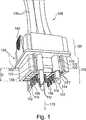
Die Direktsteckvorrichtung
Das Steckelement
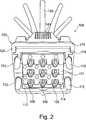
Die Steckelementaufnahme
Das Steckelement
Die Steckelementaufnahme
Durch diesen bloßen Verschiebevorgang (der durch ein Einrasten zwischen Steckelement
Jeder der Vorjustierzapfen der Vorjustiereinrichtung
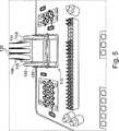
Das Steckelement
Die Kontaktelemente
Dem Fachmann wird verständlich sein, dass die 9-poligen, 15-poligen und 6-poligen Konfigurationen, die bezugnehmend auf die Figuren näher beschrieben worden sind, nur exemplarisch sind, und dass jede beliebige Anzahl von einem oder mehreren Polen bzw. Kontaktelementen
Ergänzend ist darauf hinzuweisen, dass „aufweisend“ keine anderen Elemente oder Schritte ausschließt und „eine“ oder „ein“ keine Vielzahl ausschließt. Ferner sei darauf hingewiesen, dass Merkmale oder Schritte, die mit Verweis auf eines der obigen Ausführungsbeispiele beschrieben worden sind, auch in Kombination mit anderen Merkmalen oder Schritten anderer oben beschriebener Ausführungsbeispiele verwendet werden können. Bezugszeichen in den Ansprüchen sind nicht als Einschränkung anzusehen.In addition, it should be noted that "having" does not exclude other elements or steps, and "a" or "an" does not exclude a multitude. It should also be appreciated that features or steps described with reference to any of the above embodiments may also be used in combination with other features or steps of other embodiments described above. Reference signs in the claims are not to be considered as limiting.
ZITATE ENTHALTEN IN DER BESCHREIBUNG QUOTES INCLUDE IN THE DESCRIPTION
Diese Liste der vom Anmelder aufgeführten Dokumente wurde automatisiert erzeugt und ist ausschließlich zur besseren Information des Lesers aufgenommen. Die Liste ist nicht Bestandteil der deutschen Patent- bzw. Gebrauchsmusteranmeldung. Das DPMA übernimmt keinerlei Haftung für etwaige Fehler oder Auslassungen.This list of the documents listed by the applicant has been generated automatically and is included solely for the better information of the reader. The list is not part of the German patent or utility model application. The DPMA assumes no liability for any errors or omissions.
Zitierte PatentliteraturCited patent literature
- WO 2012/107569[0004]WO 2012/107569[0004]
Claims (19)
Translated fromGermanPriority Applications (5)
| Application Number | Priority Date | Filing Date | Title |
|---|---|---|---|
| DE102013218441.7ADE102013218441A1 (en) | 2013-09-13 | 2013-09-13 | Direct plug-in device with Vorjustiereinrichtung and relative to this sliding locking device |
| US15/021,653US9812799B2 (en) | 2013-09-13 | 2014-08-21 | Printed circuit board plug device having a pre-adjusting device which serves as a locking device |
| PCT/DE2014/000427WO2015035967A1 (en) | 2013-09-13 | 2014-08-21 | Direct plug device having a pre-adjusting device and a locking device displaceable relative thereto |
| EP14793004.4AEP3044837B1 (en) | 2013-09-13 | 2014-08-21 | Direct plug device having a pre-adjusting device and a locking device displaceable relative thereto |
| CN201480061734.9ACN105723567B (en) | 2013-09-13 | 2014-08-21 | Direct plug assembly with presetting calibration device and the locking devicen that can be elapsed relative to presetting calibration device |
Applications Claiming Priority (1)
| Application Number | Priority Date | Filing Date | Title |
|---|---|---|---|
| DE102013218441.7ADE102013218441A1 (en) | 2013-09-13 | 2013-09-13 | Direct plug-in device with Vorjustiereinrichtung and relative to this sliding locking device |
Publications (1)
| Publication Number | Publication Date |
|---|---|
| DE102013218441A1true DE102013218441A1 (en) | 2015-04-02 |
Family
ID=51846429
Family Applications (1)
| Application Number | Title | Priority Date | Filing Date |
|---|---|---|---|
| DE102013218441.7AWithdrawnDE102013218441A1 (en) | 2013-09-13 | 2013-09-13 | Direct plug-in device with Vorjustiereinrichtung and relative to this sliding locking device |
Country Status (5)
| Country | Link |
|---|---|
| US (1) | US9812799B2 (en) |
| EP (1) | EP3044837B1 (en) |
| CN (1) | CN105723567B (en) |
| DE (1) | DE102013218441A1 (en) |
| WO (1) | WO2015035967A1 (en) |
Cited By (2)
| Publication number | Priority date | Publication date | Assignee | Title |
|---|---|---|---|---|
| DE102015119478A1 (en)* | 2015-11-11 | 2017-05-11 | Phoenix Contact Gmbh & Co. Kg | Electrical connection terminal |
| DE102018101669B3 (en) | 2018-01-25 | 2019-03-28 | Lumberg Connect Gmbh | Connector with locking safety cover |
Families Citing this family (42)
| Publication number | Priority date | Publication date | Assignee | Title |
|---|---|---|---|---|
| US9011177B2 (en) | 2009-01-30 | 2015-04-21 | Molex Incorporated | High speed bypass cable assembly |
| US9240644B2 (en) | 2012-08-22 | 2016-01-19 | Amphenol Corporation | High-frequency electrical connector |
| US9142921B2 (en) | 2013-02-27 | 2015-09-22 | Molex Incorporated | High speed bypass cable for use with backplanes |
| CN105580210B (en) | 2013-09-04 | 2017-07-07 | 莫列斯有限公司 | Connector system with bypass cable |
| US9685736B2 (en) | 2014-11-12 | 2017-06-20 | Amphenol Corporation | Very high speed, high density electrical interconnection system with impedance control in mating region |
| WO2016112384A1 (en)* | 2015-01-11 | 2016-07-14 | Molex, Llc | Wire to board connectors suitable for use in bypass routing assemblies |
| KR102120813B1 (en) | 2015-01-11 | 2020-06-17 | 몰렉스 엘엘씨 | Circuit board bypass assembly and components therefor |
| WO2016179263A1 (en) | 2015-05-04 | 2016-11-10 | Molex, Llc | Computing device using bypass assembly |
| TWI625010B (en) | 2016-01-11 | 2018-05-21 | Molex Llc | Cable connector assembly |
| US10424856B2 (en) | 2016-01-11 | 2019-09-24 | Molex, Llc | Routing assembly and system using same |
| TWI597896B (en) | 2016-01-19 | 2017-09-01 | Molex Llc | Integrated routing components |
| TWI746561B (en) | 2016-05-31 | 2021-11-21 | 美商安芬諾股份有限公司 | High performance cable termination |
| CN109314334B (en) | 2016-06-15 | 2021-08-20 | 申泰公司 | Overmolded leadframe with contact support and impedance matching features |
| CN110088985B (en) | 2016-10-19 | 2022-07-05 | 安费诺有限公司 | Flexible shield for ultra-high speed high density electrical interconnects |
| TWI828624B (en)* | 2017-06-13 | 2024-01-11 | 美商山姆科技公司 | Electrical connector system and method using the same |
| USD877700S1 (en) | 2017-07-17 | 2020-03-10 | Samtec, Inc. | Electrical connector |
| USD877084S1 (en) | 2017-07-17 | 2020-03-03 | Samtec, Inc. | Electrical connector |
| USD964291S1 (en) | 2017-07-21 | 2022-09-20 | Samtec, Inc. | Electrical connector |
| US11289850B2 (en) | 2017-07-21 | 2022-03-29 | Samtec, Inc. | Electrical connector having latch |
| USD823814S1 (en) | 2017-07-24 | 2018-07-24 | Samtec, Inc. | Contact wafer |
| TWI788394B (en) | 2017-08-03 | 2023-01-01 | 美商安芬諾股份有限公司 | Cable assembly and method of manufacturing the same |
| KR102732353B1 (en) | 2017-10-24 | 2024-11-21 | 샘텍, 인코포레이티드 | Right angle electrical connectors and electrical contacts for right angle connectors |
| USD896183S1 (en) | 2018-01-08 | 2020-09-15 | Samtec, Inc. | Electrical cable connector |
| US10680388B2 (en)* | 2018-03-16 | 2020-06-09 | Te Connectivity Corporation | Pluggable module for a communication system |
| US11125958B2 (en) | 2018-03-16 | 2021-09-21 | TE Connectivity Services Gmbh | Optical pluggable module for a communication system |
| US10665973B2 (en) | 2018-03-22 | 2020-05-26 | Amphenol Corporation | High density electrical connector |
| WO2019195319A1 (en) | 2018-04-02 | 2019-10-10 | Ardent Concepts, Inc. | Controlled-impedance compliant cable termination |
| FR3086110B1 (en)* | 2018-09-14 | 2021-05-28 | Safran Electronics & Defense | ELASTIC CONNECTION PIN, CONNECTOR AND ELECTRONIC DEVICE INCLUDING SUCH PINs |
| US10931062B2 (en) | 2018-11-21 | 2021-02-23 | Amphenol Corporation | High-frequency electrical connector |
| BE1026857B1 (en)* | 2018-12-10 | 2020-07-13 | Phoenix Contact E Mobility Gmbh | Connector part with a circuit board |
| USD881133S1 (en) | 2018-12-20 | 2020-04-14 | Samtec, Inc. | Contact wafer |
| US11101611B2 (en) | 2019-01-25 | 2021-08-24 | Fci Usa Llc | I/O connector configured for cabled connection to the midboard |
| WO2020154507A1 (en) | 2019-01-25 | 2020-07-30 | Fci Usa Llc | I/o connector configured for cable connection to a midboard |
| WO2020172395A1 (en) | 2019-02-22 | 2020-08-27 | Amphenol Corporation | High performance cable connector assembly |
| CN114788097A (en) | 2019-09-19 | 2022-07-22 | 安费诺有限公司 | High speed electronic system with midplane cable connector |
| TWI887339B (en) | 2020-01-27 | 2025-06-21 | 美商Fci美國有限責任公司 | High speed, high density direct mate orthogonal connector |
| WO2021154702A1 (en) | 2020-01-27 | 2021-08-05 | Fci Usa Llc | High speed connector |
| CN113258325A (en) | 2020-01-28 | 2021-08-13 | 富加宜(美国)有限责任公司 | High-frequency middle plate connector |
| US11362448B2 (en)* | 2020-06-01 | 2022-06-14 | Tag-Connect, Llc | Connector having latching pins that change angle for mounting to a circuit board |
| DE102021126140A1 (en)* | 2020-12-10 | 2022-06-15 | Hanon Systems | fastener |
| US11715902B2 (en)* | 2021-05-27 | 2023-08-01 | Te Connectivity India Private Limited | Low insertion force contact terminal |
| USD1002553S1 (en) | 2021-11-03 | 2023-10-24 | Amphenol Corporation | Gasket for connector |
Citations (3)
| Publication number | Priority date | Publication date | Assignee | Title |
|---|---|---|---|---|
| WO2010063459A1 (en)* | 2008-12-03 | 2010-06-10 | Würth Elektronik Ics Gmbh & Co. Kg | Connection assembly on circuit boards |
| US7878834B2 (en)* | 2008-04-17 | 2011-02-01 | Neil Sherman | Connector for mating a contact pin with a device |
| WO2012107569A1 (en) | 2011-02-11 | 2012-08-16 | Würth Elektronik Ics Gmbh & Co. Kg | Direct plug apparatus with a plug and an apron |
Family Cites Families (1)
| Publication number | Priority date | Publication date | Assignee | Title |
|---|---|---|---|---|
| FR2748862B1 (en)* | 1996-05-17 | 1998-07-17 | Radiall Sa | DEVICE FOR CONNECTING A COAXIAL CABLE TO A PRINTED CIRCUIT BOARD |
- 2013
- 2013-09-13DEDE102013218441.7Apatent/DE102013218441A1/ennot_activeWithdrawn
- 2014
- 2014-08-21WOPCT/DE2014/000427patent/WO2015035967A1/enactiveApplication Filing
- 2014-08-21USUS15/021,653patent/US9812799B2/enactiveActive
- 2014-08-21EPEP14793004.4Apatent/EP3044837B1/enactiveActive
- 2014-08-21CNCN201480061734.9Apatent/CN105723567B/ennot_activeExpired - Fee Related
Patent Citations (3)
| Publication number | Priority date | Publication date | Assignee | Title |
|---|---|---|---|---|
| US7878834B2 (en)* | 2008-04-17 | 2011-02-01 | Neil Sherman | Connector for mating a contact pin with a device |
| WO2010063459A1 (en)* | 2008-12-03 | 2010-06-10 | Würth Elektronik Ics Gmbh & Co. Kg | Connection assembly on circuit boards |
| WO2012107569A1 (en) | 2011-02-11 | 2012-08-16 | Würth Elektronik Ics Gmbh & Co. Kg | Direct plug apparatus with a plug and an apron |
Cited By (2)
| Publication number | Priority date | Publication date | Assignee | Title |
|---|---|---|---|---|
| DE102015119478A1 (en)* | 2015-11-11 | 2017-05-11 | Phoenix Contact Gmbh & Co. Kg | Electrical connection terminal |
| DE102018101669B3 (en) | 2018-01-25 | 2019-03-28 | Lumberg Connect Gmbh | Connector with locking safety cover |
Also Published As
| Publication number | Publication date |
|---|---|
| EP3044837A1 (en) | 2016-07-20 |
| EP3044837B1 (en) | 2017-06-28 |
| CN105723567B (en) | 2018-02-02 |
| US20160233598A1 (en) | 2016-08-11 |
| US9812799B2 (en) | 2017-11-07 |
| CN105723567A (en) | 2016-06-29 |
| WO2015035967A1 (en) | 2015-03-19 |
Similar Documents
| Publication | Publication Date | Title |
|---|---|---|
| EP3044837B1 (en) | Direct plug device having a pre-adjusting device and a locking device displaceable relative thereto | |
| EP3312940B1 (en) | Contact insert for a connector part | |
| DE102015015202B4 (en) | Connector and plug-in system | |
| DE29517358U1 (en) | Coaxial connector | |
| DE102015103949A1 (en) | Poke Home Push Button Connector | |
| EP1641085A2 (en) | Latching for a connection | |
| EP3588684A1 (en) | Direct connector and direct connection | |
| EP3358682A1 (en) | Electrical connector and electrical connector system | |
| EP3117489B1 (en) | Modular connector with alignment module for plug-in connector | |
| EP1959523A1 (en) | Keying device for plug connectors | |
| DE4013682A1 (en) | Interlocked electrical connector - has spring strip hat latches plug into base unit | |
| EP1139493A2 (en) | Electrical connector for connecting wires to an apparatus | |
| DE102008051589A1 (en) | Coupler and plug of a connector with Koshiri security | |
| DE102016116091A1 (en) | Electrical connection connector with contact protection | |
| DE2119060B2 (en) | Connector | |
| DE102016104082B3 (en) | Electrical plug-in device with a latching mechanism | |
| DE102019100219A1 (en) | Plug connection with shield support | |
| DE102014103834B4 (en) | Interference-proof connector | |
| DE202018106611U1 (en) | Data transmission and / or charging cable | |
| EP2262062B1 (en) | Connector | |
| EP3582596A1 (en) | Case of electronic device | |
| DE3022488C2 (en) | ||
| EP0073348A1 (en) | Device for the plugging-in and removal of a multicore cable for the connection of electrical modules to each other | |
| DE102023132109A1 (en) | Sensor-actuator distributor | |
| DE19619323A1 (en) | Electric plug connector e.g. for motor vehicle airbag system |
Legal Events
| Date | Code | Title | Description |
|---|---|---|---|
| R079 | Amendment of ipc main class | Free format text:PREVIOUS MAIN CLASS: H01R0012710000 Ipc:H01R0012580000 | |
| R082 | Change of representative | Representative=s name:DILG HAEUSLER SCHINDELMANN PATENTANWALTSGESELL, DE | |
| R163 | Identified publications notified | ||
| R012 | Request for examination validly filed | ||
| R119 | Application deemed withdrawn, or ip right lapsed, due to non-payment of renewal fee |