DE102013217371A1 - fuel injector - Google Patents
fuel injectorDownload PDFInfo
- Publication number
- DE102013217371A1 DE102013217371A1DE102013217371.7ADE102013217371ADE102013217371A1DE 102013217371 A1DE102013217371 A1DE 102013217371A1DE 102013217371 ADE102013217371 ADE 102013217371ADE 102013217371 A1DE102013217371 A1DE 102013217371A1
- Authority
- DE
- Germany
- Prior art keywords
- nozzle needle
- blind hole
- fuel injector
- injection
- section
- Prior art date
- Legal status (The legal status is an assumption and is not a legal conclusion. Google has not performed a legal analysis and makes no representation as to the accuracy of the status listed.)
- Pending
Links
Images


Classifications
- F—MECHANICAL ENGINEERING; LIGHTING; HEATING; WEAPONS; BLASTING
- F02—COMBUSTION ENGINES; HOT-GAS OR COMBUSTION-PRODUCT ENGINE PLANTS
- F02M—SUPPLYING COMBUSTION ENGINES IN GENERAL WITH COMBUSTIBLE MIXTURES OR CONSTITUENTS THEREOF
- F02M61/00—Fuel-injectors not provided for in groups F02M39/00 - F02M57/00 or F02M67/00
- F02M61/04—Fuel-injectors not provided for in groups F02M39/00 - F02M57/00 or F02M67/00 having valves, e.g. having a plurality of valves in series
- F02M61/06—Fuel-injectors not provided for in groups F02M39/00 - F02M57/00 or F02M67/00 having valves, e.g. having a plurality of valves in series the valves being furnished at seated ends with pintle or plug shaped extensions
- B—PERFORMING OPERATIONS; TRANSPORTING
- B05—SPRAYING OR ATOMISING IN GENERAL; APPLYING FLUENT MATERIALS TO SURFACES, IN GENERAL
- B05B—SPRAYING APPARATUS; ATOMISING APPARATUS; NOZZLES
- B05B1/00—Nozzles, spray heads or other outlets, with or without auxiliary devices such as valves, heating means
- B05B1/14—Nozzles, spray heads or other outlets, with or without auxiliary devices such as valves, heating means with multiple outlet openings; with strainers in or outside the outlet opening
- B05B1/16—Nozzles, spray heads or other outlets, with or without auxiliary devices such as valves, heating means with multiple outlet openings; with strainers in or outside the outlet opening having selectively- effective outlets
- B05B1/1627—Nozzles, spray heads or other outlets, with or without auxiliary devices such as valves, heating means with multiple outlet openings; with strainers in or outside the outlet opening having selectively- effective outlets with a selecting mechanism comprising a gate valve, a sliding valve or a cock
- B05B1/1672—Nozzles, spray heads or other outlets, with or without auxiliary devices such as valves, heating means with multiple outlet openings; with strainers in or outside the outlet opening having selectively- effective outlets with a selecting mechanism comprising a gate valve, a sliding valve or a cock the selectively-effective outlets being arranged on a tube or pipe
- B—PERFORMING OPERATIONS; TRANSPORTING
- B05—SPRAYING OR ATOMISING IN GENERAL; APPLYING FLUENT MATERIALS TO SURFACES, IN GENERAL
- B05B—SPRAYING APPARATUS; ATOMISING APPARATUS; NOZZLES
- B05B1/00—Nozzles, spray heads or other outlets, with or without auxiliary devices such as valves, heating means
- B05B1/30—Nozzles, spray heads or other outlets, with or without auxiliary devices such as valves, heating means designed to control volume of flow, e.g. with adjustable passages
- B05B1/3013—Lift valves
- F—MECHANICAL ENGINEERING; LIGHTING; HEATING; WEAPONS; BLASTING
- F02—COMBUSTION ENGINES; HOT-GAS OR COMBUSTION-PRODUCT ENGINE PLANTS
- F02M—SUPPLYING COMBUSTION ENGINES IN GENERAL WITH COMBUSTIBLE MIXTURES OR CONSTITUENTS THEREOF
- F02M61/00—Fuel-injectors not provided for in groups F02M39/00 - F02M57/00 or F02M67/00
- F02M61/16—Details not provided for in, or of interest apart from, the apparatus of groups F02M61/02 - F02M61/14
- F02M61/18—Injection nozzles, e.g. having valve seats; Details of valve member seated ends, not otherwise provided for
- F02M61/1806—Injection nozzles, e.g. having valve seats; Details of valve member seated ends, not otherwise provided for characterised by the arrangement of discharge orifices, e.g. orientation or size
- F02M61/182—Discharge orifices being situated in different transversal planes with respect to valve member direction of movement
- F—MECHANICAL ENGINEERING; LIGHTING; HEATING; WEAPONS; BLASTING
- F02—COMBUSTION ENGINES; HOT-GAS OR COMBUSTION-PRODUCT ENGINE PLANTS
- F02M—SUPPLYING COMBUSTION ENGINES IN GENERAL WITH COMBUSTIBLE MIXTURES OR CONSTITUENTS THEREOF
- F02M61/00—Fuel-injectors not provided for in groups F02M39/00 - F02M57/00 or F02M67/00
- F02M61/16—Details not provided for in, or of interest apart from, the apparatus of groups F02M61/02 - F02M61/14
- F02M61/18—Injection nozzles, e.g. having valve seats; Details of valve member seated ends, not otherwise provided for
- F02M61/1893—Details of valve member ends not covered by groups F02M61/1866 - F02M61/188
- F—MECHANICAL ENGINEERING; LIGHTING; HEATING; WEAPONS; BLASTING
- F02—COMBUSTION ENGINES; HOT-GAS OR COMBUSTION-PRODUCT ENGINE PLANTS
- F02M—SUPPLYING COMBUSTION ENGINES IN GENERAL WITH COMBUSTIBLE MIXTURES OR CONSTITUENTS THEREOF
- F02M61/00—Fuel-injectors not provided for in groups F02M39/00 - F02M57/00 or F02M67/00
- F02M61/16—Details not provided for in, or of interest apart from, the apparatus of groups F02M61/02 - F02M61/14
- F02M61/20—Closing valves mechanically, e.g. arrangements of springs or weights or permanent magnets; Damping of valve lift
- F—MECHANICAL ENGINEERING; LIGHTING; HEATING; WEAPONS; BLASTING
- F02—COMBUSTION ENGINES; HOT-GAS OR COMBUSTION-PRODUCT ENGINE PLANTS
- F02M—SUPPLYING COMBUSTION ENGINES IN GENERAL WITH COMBUSTIBLE MIXTURES OR CONSTITUENTS THEREOF
- F02M61/00—Fuel-injectors not provided for in groups F02M39/00 - F02M57/00 or F02M67/00
- F02M61/16—Details not provided for in, or of interest apart from, the apparatus of groups F02M61/02 - F02M61/14
- F02M61/18—Injection nozzles, e.g. having valve seats; Details of valve member seated ends, not otherwise provided for
- F02M61/1886—Details of valve seats not covered by groups F02M61/1866 - F02M61/188
Landscapes
- Engineering & Computer Science (AREA)
- Chemical & Material Sciences (AREA)
- Combustion & Propulsion (AREA)
- Mechanical Engineering (AREA)
- General Engineering & Computer Science (AREA)
- Fuel-Injection Apparatus (AREA)
Abstract
Translated fromGermanDescription
Translated fromGermanDie Erfindung betrifft einen Kraftstoffinjektor für Brennkraftmaschinen, wie er zur Kraftstoffeinspritzung unter hohem Druck in den Brennraum einer Brennkraftmaschine verwendet werden kann.The invention relates to a fuel injector for internal combustion engines, as it can be used for fuel injection under high pressure in the combustion chamber of an internal combustion engine.
Stand der TechnikState of the art
Aus der Offenlegungsschrift
Offenbarung der ErfindungDisclosure of the invention
Der erfindungsgemäße Kraftstoffinjektor weist demgegenüber bei ähnlicher Einspritzcharakteristik einen geringeren Verschleiß auf und erfordert gleichzeitig eine weniger hohe Fertigungsgenauigkeit.In contrast, the fuel injector according to the invention has a lower wear with a similar injection characteristic and at the same time requires less high production accuracy.
Dazu weist der Kraftstoffinjektor einen in einem Injektorkörper ausgebildeten Druckraum auf, in dem eine Düsennadel längsverschiebbar angeordnet ist, die an ihrem brennraumseitigen Ende einen sich in Brennraumrichtung verjüngenden Kegelbereich und einen Zapfenbereich mit konstantem Durchmesser d23 aufweist. Der Injektorkörper weist außerdem einen im Wesentlichen konischen Düsennadelsitz auf, von dem eine erste Einspritzöffnung ausgeht, und eine sich brennraumseitig an den Düsennadelsitz anschließende Sacklochbohrung mit einem zylindrischen Abschnitt mit dem Durchmesser d31 und mit einem Bohrungsgrund, von der eine zweite Einspritzöffnung ausgeht. Der Kegelbereich der Düsennadel wirkt mit dem Düsennadelsitz zusammen und öffnet und schließt dadurch die erste Einspritzöffnung und die zweite Einspritzöffnung gegenüber dem Druckraum. Zumindest während eines Teilhubs der Düsennadel sind die erste Einspritzöffnung und die zweite Einspritzöffnung über einen Drosselspalt, der in der Sacklochbohrung zwischen dem Zapfenbereich und der Wand der Sacklochbohrung ausgebildet ist, miteinander verbunden, und der Drosselspalt bleibt zumindest über den Teilhub konstant. Aufgrund des Drosselspalts kommt es zu keinem Kontakt bzw. nur zu einem geringfügigen Anliegen zwischen Zapfenbereich und Düsennadel und damit auch zu keinem oder nur geringem Verschleiß in diesen Bereichen. Weiterhin kann die Fertigung größere Toleranzen aufweisen als wenn der Zapfenbereich eine abdichtende Funktion erfüllen müsste.For this purpose, the fuel injector has a pressure chamber formed in an injector body, in which a nozzle needle is arranged so as to be longitudinally displaceable, which at its combustion chamber end has a conical region tapering in the combustion chamber direction and a conical region having a constant diameter d23 . The injector body also has a substantially conical nozzle needle seat, from which a first injection opening emanates, and a blind hole which adjoins the nozzle needle seat on the combustion chamber side with a cylindrical portion with the diameter d31 and with a bore bottom, from which a second injection opening originates. The conical region of the nozzle needle cooperates with the nozzle needle seat and thereby opens and closes the first injection opening and the second injection opening with respect to the pressure chamber. At least during a partial stroke of the nozzle needle, the first injection opening and the second injection opening are connected to each other via a throttle gap which is formed in the blind hole between the pin portion and the wall of the blind hole, and the throttle gap remains constant at least over the partial stroke. Due to the throttle gap, there is no contact or only a slight concern between pin portion and nozzle needle and thus no or little wear in these areas. Furthermore, the production can have greater tolerances than if the pin area would have to fulfill a sealing function.
In einer vorteilhaften Ausführung des erfindungsgemäßen Kraftstoffinjektors ist die Differenz des Durchmessers d31 der Sacklochbohrung und des Durchmessers d23 des Zapfenbereichs größer als 6 µm und kleiner als 30 µm. Damit ist der Drosselspalt im Mittel größer als 3 µm und die Toleranzkette zwischen Zapfenbereich und Wand der Sacklochbohrung kann mit bis zu 3 µm vergleichsweise groß gewählt werden solange die Düsennadel nicht durch Querkräfte belastet wird. Gleichzeitig muss die Spaltbreite kleiner als 15 µm sein, um eine ausreichende Drosselfunktion des Drosselspalts zu erreichen.In an advantageous embodiment of the fuel injector according to the invention, the difference of the diameter d31 of the blind hole and the diameter d23 of the pin portion is greater than 6 microns and less than 30 microns. Thus, the throttle gap is on average greater than 3 microns and the tolerance chain between the pin portion and wall of the blind hole can be selected comparatively large with up to 3 microns as long as the nozzle needle is not burdened by lateral forces. At the same time, the gap width must be less than 15 microns in order to achieve a sufficient throttle function of the throttle gap.
In einer weiteren vorteilhaften Ausführung sind eine oder mehrere zweite Einspritzöffnungen vorhanden, und der Durchflussquerschnitt durch den Drosselspalt ist kleiner als der summierte Durchflussquerschnitt durch die oder alle zweiten Einspritzöffnungen. Vorzugsweise beträgt der Durchflussquerschnitt durch den Drosselspalt über den Teilhub 15% bis 70% des summierten Durchflussquerschnitts durch die oder alle zweiten Einspritzöffnungen. Dadurch wird die Kraftstoffzufuhr zu den zweiten Einspritzöffnungen gedrosselt, solange der Drosselspalt vorhanden ist, was eine gute Kleinstmengenfähigkeit des Kraftstoffinjektors bedeutet.In a further advantageous embodiment, one or more second injection openings are present, and the flow cross section through the throttle gap is smaller than the summed flow cross section through the or all the second injection openings. Preferably, the flow cross section through the throttle gap over the partial stroke 15% to 70% of the summed flow cross section through the or all the second injection openings. As a result, the fuel supply to the second injection openings is throttled as long as the throttle gap is present, which means a good minimum quantity capability of the fuel injector.
Vorteilhaft taucht bei Hüben, die größer als der Teilhub sind, der Zapfenbereich aus der Sacklochbohrung, und der Durchflussquerschnitt in die Sacklochbohrung vergrößert sich gegenüber dem Drosselspalt. Zu den zweiten Einspritzöffnungen wird dadurch mehr Kraftstoff zugeführt, was notwendig ist, um höhere Motorleistungen zu realisieren.Advantageously emerges at strokes that are greater than the partial stroke, the pin portion of the blind hole, and the flow area in the blind hole increases in relation to the throttle gap. As a result, more fuel is supplied to the second injection openings, which is necessary in order to realize higher engine outputs.
In einer weiteren vorteilhaften Ausführung weist die Düsennadel einen sich brennraumseitig an den Zapfenbereich anschließenden Endbereich auf. Dadurch kann der Übergang von Teil- zu Volllast des Motors sanfter und damit verbrauchsärmer gestaltet werden, da in diesem Übergang die Kurve der Einspritzrate über der Zeit bzw. dem Hub flacher verläuft.In a further advantageous embodiment, the nozzle needle has an end region adjoining the journal region on the combustion chamber side. As a result, the transition from partial to full load of the engine can be made smoother and therefore less fuel-intensive, because in this transition the curve of the injection rate runs more slowly over time or stroke.
In einer vorteilhaften Ausführung ist der Endbereich als Kegel ausgeführt. Dadurch steigt die den zweiten Einspritzöffnungen zugeführte Kraftstoffmenge ab dem Teilhub linear an, was applikationsabhängig zu einer vorteilhaften Einspritzcharakteristik führt. In an advantageous embodiment, the end region is designed as a cone. As a result, the fuel quantity supplied to the second injection openings increases linearly from the partial lift, which, depending on the application, leads to an advantageous injection characteristic.
In einer anderen vorteilhaften Ausführung ist der Endbereich im Wesentlichen zylindrisch ausgeführt und weist wenigstens eine seitliche Ausnehmung auf. Dadurch ragt die Düsennadel mit einer Erweiterung des Zapfenbereichs auch noch ab dem Teilhub in die Sacklochbohrung, so dass es zu geringeren Desachsierungen zwischen Injektorkörper und Düsennadel kommt und damit auch zu einem geringeren Verschleißrisiko während des Düsennadelschließens. Die Form der seitlichen Ausnehmungen kann applikationsabhängig gestaltet werden, so dass der den zweiten Einspritzöffnungen zugeführte Kraftstoff ab dem Teilhub stark oder weniger stark ansteigt.In another advantageous embodiment, the end region is designed substantially cylindrical and has at least one lateral recess. As a result, the nozzle needle protrudes with an extension of the pin area even from the partial stroke in the blind hole, so that it comes to lower offsets between injector body and nozzle needle and thus to a lower risk of wear during the nozzle needle closing. The shape of the lateral recesses can be designed depending on the application, so that the fuel supplied to the second injection openings rises sharply or less strongly from the partial stroke.
Vorteilhaft ist die wenigstens eine Ausnehmung als planarer Anschliff ausgeführt. Dadurch kann die gewünschte Reduzierung der Drosselfunktion ab dem Teilhub fertigungstechnisch einfach erreicht werden.Advantageously, the at least one recess is designed as a planar polished section. Thereby, the desired reduction of the throttle function from the partial stroke manufacturing technology can be easily achieved.
In einer anderen vorteilhaften Ausführung ist die wenigstens eine Ausnehmung im Querschnitt im Wesentlichen halbkreisförmig ausgeführt. Dadurch wird die potenzielle Kontaktfläche zwischen Endbereich und Wand der Sacklochbohrung vergrößert, was zu einer besseren Führung der Düsennadel in der Sacklochbohrung führt und damit auch zu geringerem Verschleißrisiko.In another advantageous embodiment, the at least one recess is designed substantially semicircular in cross section. As a result, the potential contact surface between the end region and the wall of the blind bore is increased, which leads to a better guidance of the nozzle needle in the blind bore and thus also to a lower risk of wear.
Vorteilhaft ist bei einem Maximalhub der Düsennadel, der größer als der Teilhub ist, der Durchflussquerschnitt in die Sacklochbohrung größer als der summierte Durchflussquerschnitt durch alle zweiten Einspritzöffnungen. Dadurch wird beim Maximalhub die Einspritzcharakteristik im Wesentlichen durch die Geometrien der ersten und der zweiten Einspritzöffnungen bestimmt; eine drosselnde Funktion zwischen dem Injektorkörper und der Düsennadel ist praktisch nicht mehr vorhanden. Für den Maximalhub ist damit die Fertigungsgenauigkeit der beiden Einspritzöffnungen ausschlaggebend, während die Toleranzen des Drosselspalts diesbezüglich von untergeordneter Bedeutung sind.Advantageously, in the case of a maximum stroke of the nozzle needle, which is greater than the partial stroke, the flow cross section into the blind bore is greater than the summed flow cross section through all second injection openings. As a result, the injection characteristic is determined essentially by the geometries of the first and the second injection openings at the maximum stroke; a throttling function between the injector body and the nozzle needle is virtually eliminated. For the maximum stroke so that the manufacturing accuracy of the two injection ports is crucial, while the tolerances of the throttle gap in this respect are of minor importance.
Vorteilhafterweise sind mehrere erste Einspritzöffnungen und/oder mehrere zweite Einspritzöffnungen vorhanden. Dadurch kann eine gleichmäßige Einspritzung des Kraftstoffs in den Brennraum erzielt werden.Advantageously, a plurality of first injection openings and / or a plurality of second injection openings are present. As a result, a uniform injection of the fuel into the combustion chamber can be achieved.
Zeichnungendrawings
Beschreibungdescription
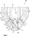
In
Im Druckraum
Der Injektorkörper
Im dargestellten geschlossenen Betriebszustand wirkt die Düsennadel
Zur Einspritzung von Kraftstoff durch die beiden Einspritzöffnungen
Bis zu einem Teilhub s der Düsennadel
Durchflussquerschnitt durch Drosselspalt ADS ergibt sich zu:
Durchflussquerschnitt durch alle × zweiten Einspritzöffnungen A2.EÖ:
Bis zum Teilhub (s) soll gelten: ADS < ADS2.EÖ
Vorzugsweise soll bis zum Teilhub (s) gelten: 15%·A2.EÖ < ADS < 70%·A2.EÖ
Bis zum Teilhub s wird die Einspritzcharakteristik somit im Wesentlichen durch die Geometrien der ersten Einspritzöffnung
Ab dem Teilhub s taucht der Zapfenbereich
Beim Maximalhub v wird die Einspritzcharakteristik somit im Wesentlichen durch die Geometrien der ersten und zweiten Einspritzöffnungen
Das Ausführungsbeispiel der
ZITATE ENTHALTEN IN DER BESCHREIBUNG QUOTES INCLUDE IN THE DESCRIPTION
Diese Liste der vom Anmelder aufgeführten Dokumente wurde automatisiert erzeugt und ist ausschließlich zur besseren Information des Lesers aufgenommen. Die Liste ist nicht Bestandteil der deutschen Patent- bzw. Gebrauchsmusteranmeldung. Das DPMA übernimmt keinerlei Haftung für etwaige Fehler oder Auslassungen.This list of the documents listed by the applicant has been generated automatically and is included solely for the better information of the reader. The list is not part of the German patent or utility model application. The DPMA assumes no liability for any errors or omissions.
Zitierte PatentliteraturCited patent literature
- DE 2920100 A1[0002]DE 2920100 A1[0002]
Claims (11)
Translated fromGermanPriority Applications (8)
| Application Number | Priority Date | Filing Date | Title |
|---|---|---|---|
| DE102013217371.7ADE102013217371A1 (en) | 2013-08-30 | 2013-08-30 | fuel injector |
| BR112016004058-9ABR112016004058B1 (en) | 2013-08-30 | 2014-08-05 | FUEL INJECTOR FOR INTERNAL COMBUSTION ENGINES FOR HIGH PRESSURE FUEL INJECTION |
| JP2016537197AJP6234583B2 (en) | 2013-08-30 | 2014-08-05 | Fuel injector |
| KR1020167004882AKR102167304B1 (en) | 2013-08-30 | 2014-08-05 | Fuel injector |
| US14/915,283US9835124B2 (en) | 2013-08-30 | 2014-08-05 | Fuel injector |
| CN201480047915.6ACN105492757B (en) | 2013-08-30 | 2014-08-05 | Fuel injector |
| PCT/EP2014/066770WO2015028261A1 (en) | 2013-08-30 | 2014-08-05 | Fuel injector |
| EP14749777.0AEP3039283A1 (en) | 2013-08-30 | 2014-08-05 | Fuel injector |
Applications Claiming Priority (1)
| Application Number | Priority Date | Filing Date | Title |
|---|---|---|---|
| DE102013217371.7ADE102013217371A1 (en) | 2013-08-30 | 2013-08-30 | fuel injector |
Publications (1)
| Publication Number | Publication Date |
|---|---|
| DE102013217371A1true DE102013217371A1 (en) | 2015-03-05 |
Family
ID=51300730
Family Applications (1)
| Application Number | Title | Priority Date | Filing Date |
|---|---|---|---|
| DE102013217371.7APendingDE102013217371A1 (en) | 2013-08-30 | 2013-08-30 | fuel injector |
Country Status (8)
| Country | Link |
|---|---|
| US (1) | US9835124B2 (en) |
| EP (1) | EP3039283A1 (en) |
| JP (1) | JP6234583B2 (en) |
| KR (1) | KR102167304B1 (en) |
| CN (1) | CN105492757B (en) |
| BR (1) | BR112016004058B1 (en) |
| DE (1) | DE102013217371A1 (en) |
| WO (1) | WO2015028261A1 (en) |
Cited By (1)
| Publication number | Priority date | Publication date | Assignee | Title |
|---|---|---|---|---|
| CN108194240A (en)* | 2018-01-19 | 2018-06-22 | 南京世界村汽车动力有限公司 | A kind of engine nozzle |
Families Citing this family (8)
| Publication number | Priority date | Publication date | Assignee | Title |
|---|---|---|---|---|
| NL1041770B1 (en)* | 2016-03-18 | 2017-10-03 | Cereus Tech B V | Improved fuel injection devices. |
| US9915215B2 (en)* | 2016-04-28 | 2018-03-13 | Caterpillar Inc. | Fuel injector for pulsed injections and system and method thereof |
| US11260407B2 (en)* | 2016-08-30 | 2022-03-01 | Ford Global Technologies, Llc | Methods and systems for a fuel injector assembly |
| CN106996349A (en)* | 2017-04-19 | 2017-08-01 | 四川森洁燃气设备有限公司 | A kind of combustion gas adjustable type spout structure |
| RU2700119C2 (en)* | 2017-10-10 | 2019-09-12 | Федеральное государственное бюджетное образовательное учреждение высшего образования "Московский автомобильно-дорожный государственный технический университет (МАДИ)" | Sprayer for diesel engine |
| WO2021178118A1 (en)* | 2020-03-02 | 2021-09-10 | Cummins Inc. | Fuel injector having multiple rows of spray holes with different cross-sectional shapes for flow modulation |
| CN112228262B (en)* | 2020-09-30 | 2022-07-22 | 江苏大学 | Diesel injector based on nozzle internal vortex cavitation induction hollow spraying structure |
| GB2616442B (en)* | 2022-03-08 | 2024-10-30 | Phinia Delphi Luxembourg Sarl | Injector Nozzle |
Citations (1)
| Publication number | Priority date | Publication date | Assignee | Title |
|---|---|---|---|---|
| DE2920100A1 (en) | 1979-05-18 | 1980-11-27 | Bosch Gmbh Robert | FUEL INJECTION NOZZLE WITH CONTROLLED INJECTION CROSS SECTION FOR INTERNAL COMBUSTION ENGINES |
Family Cites Families (26)
| Publication number | Priority date | Publication date | Assignee | Title |
|---|---|---|---|---|
| US1833080A (en)* | 1931-01-14 | 1931-11-24 | Worthington Pump & Mach Corp | Fuel injection or spray valve |
| FR1190361A (en)* | 1957-01-23 | 1959-10-12 | Maschf Augsburg Nuernberg Ag | Nozzle for internal combustion engines |
| US3559892A (en)* | 1968-06-18 | 1971-02-02 | Ambac Ind | Fuel injection nozzle with auxiliary spray orifice |
| DE2726074A1 (en)* | 1977-06-10 | 1978-12-21 | Maschf Augsburg Nuernberg Ag | FUEL INJECTOR |
| DE2803774A1 (en)* | 1978-01-28 | 1979-08-02 | Audi Nsu Auto Union Ag | FUEL INJECTOR FOR INJECTION COMBUSTION MACHINES |
| JPS5882069A (en)* | 1981-11-09 | 1983-05-17 | Nissan Motor Co Ltd | fuel injection nozzle |
| JPS61130487A (en) | 1984-11-29 | 1986-06-18 | Matsushita Electric Ind Co Ltd | Plasma injection CVD equipment |
| JPS6336662U (en)* | 1986-08-27 | 1988-03-09 | ||
| JPH07259704A (en)* | 1994-03-24 | 1995-10-09 | Nissan Diesel Motor Co Ltd | Fuel injection nozzle for internal combustion engine |
| US5947389A (en)* | 1996-06-06 | 1999-09-07 | Zexel Corporation | Variable nozzle hole type fuel injection nozzle |
| JPH10141179A (en)* | 1996-11-08 | 1998-05-26 | Zexel Corp | Fuel injection nozzle |
| JPH10281038A (en)* | 1997-04-01 | 1998-10-20 | Denso Corp | Fuel injection valve |
| JPH11280610A (en)* | 1998-03-30 | 1999-10-15 | Isuzu Motors Ltd | Fuel injection nozzle |
| JP2000145586A (en)* | 1998-11-05 | 2000-05-26 | Mitsubishi Motors Corp | Fuel injection valve |
| DE19942370A1 (en)* | 1999-09-04 | 2001-03-22 | Bosch Gmbh Robert | Injection nozzle for internal combustion engines with an annular groove in the nozzle needle |
| DE10207189A1 (en)* | 2001-03-03 | 2002-09-12 | Fev Motorentech Gmbh | Switchable injection device for injecting different fuel quantities, has nozzle holes in only a first plane or in two planes exposed to fuel depending on the valve needle's stroke |
| JP2002322957A (en)* | 2001-04-26 | 2002-11-08 | Toyota Motor Corp | Fuel injection device |
| DE60219396T2 (en)* | 2001-08-06 | 2007-12-20 | Toyota Jidosha Kabushiki Kaisha, Toyota | Internal combustion engine |
| JP2003049751A (en)* | 2001-08-06 | 2003-02-21 | Toyota Motor Corp | Fuel injection valve |
| DE10204656A1 (en)* | 2002-02-05 | 2003-09-25 | Bosch Gmbh Robert | Fuel injector |
| DE10307873A1 (en)* | 2003-02-25 | 2004-09-02 | Robert Bosch Gmbh | Blind hole and seat hole injection nozzle for an internal combustion engine with a transition cone between the blind hole and nozzle needle seat |
| JP2006063951A (en)* | 2004-08-30 | 2006-03-09 | Toyota Motor Corp | Fluid injection nozzle |
| CN2839602Y (en)* | 2005-10-24 | 2006-11-22 | 天津市天动技术中心 | Diesel engine combustion chamber fuel-injection nozzle |
| DE102006053288A1 (en)* | 2006-11-13 | 2008-05-15 | Robert Bosch Gmbh | Fuel injector for injecting fuel into combustion chamber of internal-combustion engine, has combustion chamber pressure surface limiting combustion chamber provided at nozzle needle, and loaded with pressure obtained in combustion chamber |
| DE102009042155A1 (en)* | 2009-09-21 | 2011-04-07 | Continental Automotive Gmbh | Fuel injection valve for an internal combustion engine |
| DE102010040940A1 (en)* | 2010-09-17 | 2012-03-22 | Robert Bosch Gmbh | Nozzle assembly for common-rail injector for injecting fuel into combustion chamber of internal combustion engine, has valve seat forming frustum-shaped portion and partially released by depression in die body |
- 2013
- 2013-08-30DEDE102013217371.7Apatent/DE102013217371A1/enactivePending
- 2014
- 2014-08-05USUS14/915,283patent/US9835124B2/enactiveActive
- 2014-08-05WOPCT/EP2014/066770patent/WO2015028261A1/enactiveApplication Filing
- 2014-08-05KRKR1020167004882Apatent/KR102167304B1/enactiveActive
- 2014-08-05EPEP14749777.0Apatent/EP3039283A1/ennot_activeCeased
- 2014-08-05BRBR112016004058-9Apatent/BR112016004058B1/enactiveIP Right Grant
- 2014-08-05JPJP2016537197Apatent/JP6234583B2/enactiveActive
- 2014-08-05CNCN201480047915.6Apatent/CN105492757B/enactiveActive
Patent Citations (1)
| Publication number | Priority date | Publication date | Assignee | Title |
|---|---|---|---|---|
| DE2920100A1 (en) | 1979-05-18 | 1980-11-27 | Bosch Gmbh Robert | FUEL INJECTION NOZZLE WITH CONTROLLED INJECTION CROSS SECTION FOR INTERNAL COMBUSTION ENGINES |
Cited By (1)
| Publication number | Priority date | Publication date | Assignee | Title |
|---|---|---|---|---|
| CN108194240A (en)* | 2018-01-19 | 2018-06-22 | 南京世界村汽车动力有限公司 | A kind of engine nozzle |
Also Published As
| Publication number | Publication date |
|---|---|
| KR102167304B1 (en) | 2020-10-19 |
| EP3039283A1 (en) | 2016-07-06 |
| BR112016004058A2 (en) | 2017-08-01 |
| CN105492757B (en) | 2018-10-23 |
| JP2016532816A (en) | 2016-10-20 |
| WO2015028261A1 (en) | 2015-03-05 |
| BR112016004058B1 (en) | 2022-05-10 |
| JP6234583B2 (en) | 2017-11-22 |
| US20160215745A1 (en) | 2016-07-28 |
| US9835124B2 (en) | 2017-12-05 |
| CN105492757A (en) | 2016-04-13 |
| KR20160048085A (en) | 2016-05-03 |
Similar Documents
| Publication | Publication Date | Title |
|---|---|---|
| DE102013217371A1 (en) | fuel injector | |
| DE2750929A1 (en) | FUEL INJECTION NOZZLE FOR COMBUSTION MACHINES | |
| DE102008039920A1 (en) | Nozzle body, nozzle assembly and fuel injector, and method of making a nozzle body | |
| EP1509693B1 (en) | Fuel injection valve for internal combustion engines | |
| DD142739A1 (en) | FUEL INJECTION DEVICE FOR INTERNAL COMBUSTION ENGINES | |
| DE10315967A1 (en) | Fuel ejecting valve for internal combustion engine, has injecting duct with conical sections, each narrowed along the flow direction and has different opening angles | |
| DE10322826A1 (en) | Fuel injection valve for internal combustion engines | |
| DE102013224404A1 (en) | fuel injector | |
| DE102010030344A1 (en) | Injector, in particular common-rail injector, as well as fuel injection system with an injector | |
| DE102012211169A1 (en) | Fuel injector for injecting fuel to chamber of combustion engine, has injection port that is hydraulically connected with high pressure space via through-hole, such that pressure chamber is fuel-supplied by lifting nozzle needle | |
| DE102016208055A1 (en) | Fuel injection valve for internal combustion engines | |
| EP2798192B1 (en) | Fuel injector for combustion engine | |
| DE102005010453A1 (en) | Fuel injection valve for internal combustion engines | |
| DE102010030424A1 (en) | Control valve for controlling nozzle needle of common-rail fuel injector, has control valve seat and/or seal surface comprising micro-structure, where seal surface is formed at control valve bolt | |
| DE112007000904B4 (en) | Injection device for an internal combustion engine | |
| DE102005020365A1 (en) | Valve, in particular fuel injection valve | |
| DE10318989A1 (en) | Fuel injection valve, for an IC motor, has a ring groove at the valve needle in a constant hydraulic link with the fuel-filled pressure zone and its downstream edge acting a sealing edge, to reduce wear at the valve seat | |
| DE102004047183A1 (en) | Fuel injection valve for internal combustion engine, has valve pin with valve sealing surface, which cooperates with valve seat, where surface or seat is provided with coating that exhibits high friction value when mating with steel | |
| DE102011082666A1 (en) | Fuel injector, particularly for common-rail-injection system, has nozzle needle, which closes nozzle hole assembly in nozzle body in closed position, where nozzle needle is arranged in high-pressure chamber in nozzle body | |
| EP1176306A2 (en) | Fuel injection system for internal combustion engine | |
| DE102015212467A1 (en) | Injection nozzle for a fuel injection system | |
| DE102013225387A1 (en) | Connecting portion between a high pressure passage and a high pressure chamber and fuel injection component with a connection portion | |
| DE102013219568A1 (en) | Fuel injection valve and a method for its production | |
| DE4343118A1 (en) | Solenoid valve armature | |
| DE10254184A1 (en) | Guide part in a bore in a housing and injector for fuel injection |
Legal Events
| Date | Code | Title | Description |
|---|---|---|---|
| R012 | Request for examination validly filed |