DE102013212909A1 - Machine component for a multi-winding electrical machine - Google Patents
Machine component for a multi-winding electrical machineDownload PDFInfo
- Publication number
- DE102013212909A1 DE102013212909A1DE102013212909.2ADE102013212909ADE102013212909A1DE 102013212909 A1DE102013212909 A1DE 102013212909A1DE 102013212909 ADE102013212909 ADE 102013212909ADE 102013212909 A1DE102013212909 A1DE 102013212909A1
- Authority
- DE
- Germany
- Prior art keywords
- groove
- winding
- machine component
- plug
- elements
- Prior art date
- Legal status (The legal status is an assumption and is not a legal conclusion. Google has not performed a legal analysis and makes no representation as to the accuracy of the status listed.)
- Withdrawn
Links
- 238000004804windingMethods0.000titleclaimsabstractdescription119
- 238000000034methodMethods0.000claimsdescription18
- 239000004020conductorSubstances0.000claimsdescription14
- 238000009413insulationMethods0.000claimsdescription14
- 238000010276constructionMethods0.000abstractdescription2
- 238000010586diagramMethods0.000description3
- 230000013011matingEffects0.000description2
- 238000000926separation methodMethods0.000description2
- 230000006978adaptationEffects0.000description1
- 230000001419dependent effectEffects0.000description1
- 238000010292electrical insulationMethods0.000description1
- 238000005265energy consumptionMethods0.000description1
- 238000005516engineering processMethods0.000description1
- 238000003780insertionMethods0.000description1
- 230000037431insertionEffects0.000description1
Images


Classifications
- H—ELECTRICITY
- H02—GENERATION; CONVERSION OR DISTRIBUTION OF ELECTRIC POWER
- H02K—DYNAMO-ELECTRIC MACHINES
- H02K3/00—Details of windings
- H02K3/04—Windings characterised by the conductor shape, form or construction, e.g. with bar conductors
- H02K3/12—Windings characterised by the conductor shape, form or construction, e.g. with bar conductors arranged in slots
- H—ELECTRICITY
- H02—GENERATION; CONVERSION OR DISTRIBUTION OF ELECTRIC POWER
- H02K—DYNAMO-ELECTRIC MACHINES
- H02K15/00—Processes or apparatus specially adapted for manufacturing, assembling, maintaining or repairing of dynamo-electric machines
- H02K15/06—Embedding prefabricated windings in the machines
- H02K15/062—Windings in slots; Salient pole windings
- H02K15/063—Windings for large electric machines, e.g. bar windings
- H—ELECTRICITY
- H02—GENERATION; CONVERSION OR DISTRIBUTION OF ELECTRIC POWER
- H02K—DYNAMO-ELECTRIC MACHINES
- H02K15/00—Processes or apparatus specially adapted for manufacturing, assembling, maintaining or repairing of dynamo-electric machines
- H02K15/08—Forming windings by laying conductors into or around core parts
- H02K15/085—Forming windings by laying conductors into or around core parts by laying conductors into slotted stators
- H—ELECTRICITY
- H02—GENERATION; CONVERSION OR DISTRIBUTION OF ELECTRIC POWER
- H02K—DYNAMO-ELECTRIC MACHINES
- H02K3/00—Details of windings
- H02K3/04—Windings characterised by the conductor shape, form or construction, e.g. with bar conductors
- H02K3/28—Layout of windings or of connections between windings
- H—ELECTRICITY
- H02—GENERATION; CONVERSION OR DISTRIBUTION OF ELECTRIC POWER
- H02K—DYNAMO-ELECTRIC MACHINES
- H02K2213/00—Specific aspects, not otherwise provided for and not covered by codes H02K2201/00 - H02K2211/00
- H02K2213/03—Machines characterised by numerical values, ranges, mathematical expressions or similar information
Landscapes
- Engineering & Computer Science (AREA)
- Power Engineering (AREA)
- Manufacturing & Machinery (AREA)
- Windings For Motors And Generators (AREA)
Abstract
Translated fromGermanDescription
Translated fromGermanTechnisches GebietTechnical area
Die vorliegende Erfindung betrifft Maschinenkomponenten für elektrische Maschinen, insbesondere Statoren oder Rotoren, in denen Nuten mit eingebrachten Spulenseiten von Wicklungen vorgesehen sind. Insbesondere betrifft die vorliegende Erfindung Maßnahmen zur Erhöhung des Nutfüllfaktors in den Nuten von Maschinenkomponenten.The present invention relates to machine components for electrical machines, in particular stators or rotors, in which grooves are provided with introduced coil sides of windings. In particular, the present invention relates to measures for increasing the slot fill factor in the grooves of machine components.
Stand der TechnikState of the art
Bei einer elektrischen Maschinen mit Spulenwicklungen wird die Leistungsdichte maßgeblich durch einen Nutfüllungsgrad von in Nuten einer Maschinenkomponente, wie z. B. in den Stator, eingebrachten Spulenseiten bestimmt. Der den Nutfüllungsgrad angebende elektrische Nutfüllfaktor ergibt sich aus dem Verhältnis zwischen der Querschnittsfläche einer Nut und der Querschnittsfläche der in der Nut befindlichen, die Wicklungen bildenden Spulenleiter.In an electrical machine with coil windings, the power density is determined by a Nutfüllungsgrad of in grooves of a machine component, such. B. in the stator, introduced coil sides. The groove fill factor indicating the groove fill factor is given by the ratio between the cross-sectional area of a groove and the cross-sectional area of the in-slot coil conductors forming the windings.
Durch direktes Wickeln der Spulenseiten der Wicklungen z.B. mithilfe einer Nadelwickeltechnik wird der Spulenleiter (Spulendraht) durch die Nuten der Komponente eingezogen. Dieses Verfahren bietet eine hohe Flexibilität aufgrund der Möglichkeit, durch die Wahl der Windungszahl beliebige effektive Wicklungsquerschnitte und -konfigurationen auf identischen Maschinen zu verarbeiten. Prozessbedingt lassen sich hier in der Regel allerdings nur Spulenleiter mit runden Querschnitten verarbeiten. Selbst bei orthozyklischen Wicklungen von nicht isolierten Drähten, ohne Verwendung von Nutisolation und Nutabschlusspapier ist der elektrische Nutfüllfaktor aus geometrischen Gründen meist auf unter 90% begrenzt. Durch Vorsehen von Nutisolationselementen, durch Vorsehen der den Spulenleiter umgebenden Drahtisolation sowie aufgrund der beim Einziehen der Spulenleiter herrschenden Reibungsverhältnisse sind in der Praxis jedoch nur Nutfüllfaktoren von ca. 45% bis 50% erreichbar.By directly winding the coil sides of the windings, e.g. By means of a needle winding technique, the coil conductor (coil wire) is drawn through the grooves of the component. This method offers a high degree of flexibility due to the possibility of processing any effective winding cross-sections and configurations on identical machines by the choice of the number of turns. Due to the process, however, only coil conductors with round cross-sections can normally be processed here. Even with orthocyclic windings of non-insulated wires, without use of slot insulation and Nutabschlusspapier the electrical Nutfüllfaktor is limited for geometric reasons usually below 90%. By providing Nutisolationselementen, by providing the surrounding the coil conductor wire insulation and due to the prevailing upon insertion of the coil conductor friction conditions in practice, however, only Nutfüllfaktoren of about 45% to 50% can be achieved.
Mit anderen Verfahren, wie beispielsweise durch eine Stecktechnik, zum Einbringen der Spulenseiten in die Nuten der Maschinenkomponente können höhere Nutfüllfaktoren erreicht werden. Bei der Stecktechnik werden Steckwicklungen mit definiertem Leiterquerschnitt, der oftmals deutlich größer ist als der von Spulendrähten, in axialer Richtung in die Nuten eingesteckt. Dieses Verfahren hat jedoch den Nachteil, dass es sich schlecht bzw. nur mit hohem Aufwand auf andere Baugrößen der Maschinenkomponente anwenden lässt, insbesondere bei geänderten Nutabmessungen. Die Anpassung der Leitergeometrie an einen geänderten Nutquerschnitt führt in der Regel dazu, dass die Werkzeuge zur Herstellung der Steckwicklungen angepasst bzw. neu konstruiert werden müssen.With other methods, such as by a plug-in technique, for introducing the coil sides in the grooves of the machine component higher Nutfüllfaktoren can be achieved. In the plug-in technique, plug-in windings with a defined conductor cross-section, which is often significantly larger than that of coil wires, are plugged into the slots in the axial direction. However, this method has the disadvantage that it can be applied poorly or only with great effort to other sizes of the machine component, especially with changed groove dimensions. The adaptation of the conductor geometry to a modified groove cross-section usually leads to the tools for the production of the plug windings must be adapted or redesigned.
Es ist Aufgabe der vorliegenden Erfindung, ein Verfahren zum Bereitstellen einer mit einer oder mehreren Wicklungen versehenen Maschinenkomponente für eine elektrische Maschine zur Verfügung zu stellen, die einen möglichst hohen Nutfüllfaktor aufweist, wobei die Art der Bewicklung eine große Flexibilität aufweist, so dass die Art der Bewicklung auch ohne hohen Aufwand auf andere Baugrößen der Maschinenkomponente angewandt werden kann. Insbesondere ist es wünschenswert, bei hohem Nutfüllfaktor einen hohen Freiheitsgrad hinsichtlich der Wahl der Wicklungsquerschnitte und -verschaltungen zu erreichen.It is the object of the present invention to provide a method for providing a machine component provided with one or more windings for an electrical machine, which has the highest possible slot fill factor, the type of winding having a high degree of flexibility, so that the type of motor Wrapping can be applied to other sizes of the machine component without much effort. In particular, it is desirable to achieve a high degree of freedom with regard to the choice of the winding cross-sections and interconnections with a high slot fill factor.
Offenbarung der ErfindungDisclosure of the invention
Diese Aufgabe wird durch die Maschinenkomponente für eine elektrische Maschine gemäß Anspruch 1 sowie durch die elektrische Maschine und das Verfahren zum Aufbau einer Maschinenkomponente für eine elektrische Maschine gemäß den nebengeordneten Ansprüchen gelöst.This object is achieved by the machine component for an electric machine according to
Weitere vorteilhafte Ausgestaltungen der vorliegenden Erfindung sind in den abhängigen Ansprüchen angegeben.Further advantageous embodiments of the present invention are specified in the dependent claims.
Gemäß einem ersten Aspekt ist eine Maschinenkomponente für eine elektrische Maschine, insbesondere eine Statoranordnung oder eine Rotoranordnung, vorgesehen, umfassend:
- – einen Komponentenkörper, der Nuten aufweist;
- – einen oder mehrere erste Wicklungsteile, die mithilfe eines oder mehrerer Steckelemente zum Aufbau einer Steckwicklung ausgebildet sind; und
- – einen oder mehrere zweite Wicklungsteile, die als Drahtwicklungen mit Spulendrähten ausgebildet sind.
- A component body having grooves;
- - One or more first winding parts, which are formed by means of one or more plug-in elements for the construction of a plug-in winding; and
- - One or more second winding parts, which are formed as wire windings with coil wires.
Eine Idee der obigen Maschinenkomponente besteht darin, zu deren Herstellung verschiedene Wicklungstechniken miteinander zu kombinieren und dadurch den bisher bestehenden Zielkonflikt zwischen hohem Nutfüllfaktor und gleichzeitig hoher Flexibilität der Fertigung und Auslegung zu durchbrechen. Dies wird dadurch erreicht, dass ein erster Abschnitt der Nuten in der Maschinenkomponente durch Steckelemente zum Aufbau einer Steckwicklung bestückt wird und ein zweiter Abschnitt der Nuten mit einer Spule aus einem Spulendraht versehen wird, die entweder als direkt in die Maschinenkomponente gewickelte Spule z.B. mithilfe einer Nadelwicklung oder als vorab gewickelte Einzugswicklung ausgebildet sein kann. Durch diese Kombination der Wicklungstechniken kann ein relativ hoher Nutfüllfaktor erreicht werden, indem Steckelemente in den ersten Abschnitt der Nut der Maschinenkomponente eingesetzt werden, die mit ihren Querschnitten an den Querschnitt der Nut anpasst sind. Weiterhin kann durch Verwenden einer geeigneten Drahtwicklung mit einer anpassbaren Windungszahl der Querschnitt der durch den Spulendraht gebildeten Wicklungen in dem zweiten Abschnitt der Nut frei gewählt werden. Dies ermöglicht eine hohe fertigungs- und auslegungstechnische Flexibilität.One idea of the above machine component is to combine different winding techniques with one another for their production, thereby breaking the previously existing conflict of goals between a high slot fill factor and at the same time a high degree of flexibility in production and design. This is accomplished by populating a first portion of the grooves in the machine component with plug-in mating components and providing a second portion of the grooves with a spool of coil wire, either as a spool wound directly into the machine component, for example by means of a needle winding or may be formed as a pre-wound pull-in winding. By this combination of winding techniques, a relatively high Nutfüllfaktor can be achieved by inserting elements into the first section of the groove Machine components are used, which are adapted with their cross-sections of the cross-section of the groove. Furthermore, by using a suitable wire winding with an adaptable number of turns, the cross section of the windings formed by the coil wire can be freely selected in the second portion of the groove. This allows a high production and design flexibility.
Ein weiterer Vorteil der obigen Maschinenkomponente besteht darin, dass die beiden mit unterschiedlichen Wicklungstechniken hergestellten Wicklungen auch getrennt voneinander schaltbar sind, wodurch weitere Anwendungen und Ansteuerungen der elektrischen Maschine realisiert werden können. So kann eine Teilabschaltung für einen optimierten Hochlauf einer als Elektroantrieb verwendeten elektrischen Maschine mit einer derartigen Bewicklung unter Verwendung von nur einem der Wicklungsteile in einer Nut genutzt werden oder es kann bei geringerem Leistungsabruf (geringerem Drehmoment) der Energieverbrauch gesenkt werden. Für den Fall einer Sehnung, bei der zwei Phasenwicklungen in einer Nut vorgesehen sind, d. h. wenn die in dem ersten Abschnitt befindliche Wicklung und die in dem zweiten Abschnitt befindliche Wicklung jeweils verschiedenen Phasen zugeordnet sind, ist es u.U. nicht erforderlich, einen Phasentrenner einzufügen, da die Trennung der Phasen über die räumliche Trennung zwischen den zwei Abschnitten der Wicklungen erreicht wird.Another advantage of the above machine component is that the two windings made with different winding techniques are also switchable separately from each other, whereby further applications and controls of the electric machine can be realized. Thus, a partial shutdown for an optimized run-up of an electrical machine used as an electric drive with such a winding using only one of the winding parts in a groove can be used or it can be reduced with lower power consumption (lower torque) energy consumption. In the case of a chord, in which two phase windings are provided in a groove, i. H. if the winding located in the first section and the winding located in the second section are each assigned different phases, it may be. it is not necessary to insert a phase separator as the separation of the phases is achieved via the spatial separation between the two sections of the windings.
Weiterhin können die Steckelemente zu einer oder mehreren Wicklungen verschaltet sein.Furthermore, the plug-in elements can be interconnected to one or more windings.
Insbesondere können die Steckelemente jeweils einen Leiterabschnitt aufweisen, der einen ersten Abschnitt der Nut im Wesentlichen vollständig ausfüllt und insbesondere mit einem rechteckigen oder trapezförmigen Querschnitt ausgebildet ist.In particular, the plug-in elements may each have a conductor section which substantially completely fills a first section of the groove and is in particular formed with a rectangular or trapezoidal cross-section.
Gemäß einer Ausführungsform können die Leiterabschnitte der Steckelemente bezüglich einer Tiefe der Nut übereinander und/oder nebeneinander liegen.According to one embodiment, the conductor sections of the plug-in elements can lie one above the other and / or next to each other with respect to a depth of the groove.
Weiterhin können das eine oder die mehreren Steckelemente jeweils von einer Drahtisolation und/oder insgesamt von einer ersten Nutisolation umgeben sein.Furthermore, the one or more plug-in elements can each be surrounded by a wire insulation and / or a total of a first slot insulation.
Es kann vorgesehen sein, dass die Drahtwicklungen in einem zweiten Abschnitt der Nut angeordnet sind, der insbesondere näher an einer Nutöffnung der Nut angeordnet ist als die ersten Wicklungsteile.It can be provided that the wire windings are arranged in a second section of the groove, which is arranged in particular closer to a slot opening of the groove than the first winding parts.
Alternativ kann vorgesehen sein, dass die Drahtwicklungen in einem ersten Abschnitt der Nut angeordnet sind, der insbesondere näher an einem Nutgrund der Nut angeordnet ist als die zweiten Wicklungsteile.Alternatively it can be provided that the wire windings are arranged in a first portion of the groove, which is arranged in particular closer to a groove bottom of the groove than the second winding parts.
Ferner können die Spulendrähte der Drahtwicklungen jeweils von einer Drahtisolation und/oder insgesamt von einer zweiten Nutisolation umgeben sein.Furthermore, the coil wires of the wire windings can each be surrounded by a wire insulation and / or in total by a second slot insulation.
Die Steckelemente können jeweils einen größeren Querschnitt aufweisen als die Spulendrähte, die zum Ausbilden der einer direkt gewickelten Spule oder einer Einzugswicklung verwendet werden.The plug-in elements can each have a larger cross-section than the coil wires used to form a directly wound coil or a pull-in winding.
Gemäß einer Ausführungsform können die ersten Wicklungsteile einen Nutfüllfaktor von mehr als 50% in einem ersten Abschnitt der Nut und die zweiten Wicklungsteile einen Nutfüllfaktor von weniger als 50% in einem zweiten Abschnitt der Nut aufweisen.According to one embodiment, the first winding parts may have a groove fill factor of more than 50% in a first portion of the groove and the second winding parts may have a groove fill factor of less than 50% in a second portion of the groove.
Gemäß einem weiteren Aspekt ist eine elektrische Maschine mit der obigen Maschinenkomponente vorgesehen.In another aspect, an electric machine with the above machine component is provided.
Gemäß einem weiteren Aspekt ist ein Verfahren zum Aufbau einer Maschinenkomponente vorgesehen, die einen Komponentenkörper mit mehreren an einem magnetischen Rückschlussbereich endenden Nuten aufweist, umfassend die folgenden Schritte:
- – Einbringen eines oder mehrerer erster Wicklungsteile durch Stecken von einem oder mehreren Steckelementen zum Bilden einer Steckwicklung in einem ersten Abschnitt einer oder mehrerer der Nuten; und
- – Einbringen eines oder mehrerer zweiter Wicklungsteile, die als Drahtwicklungen mit Spulendrähten ausgebildet sind, in einem zweiten Abschnitt einer oder mehrerer der Nuten.
- - inserting one or more first winding parts by inserting one or more plug-in elements to form a plug-in winding in a first portion of one or more of the grooves; and
- - Introducing one or more second winding parts, which are formed as wire windings with coil wires, in a second portion of one or more of the grooves.
Weiterhin kann der erste Abschnitt rückschlussbereichsnah und der zweite Bereich rückschlussbereichsfern in der Maschinenkomponente angeordnet sein.Furthermore, the first section can be arranged close to the return area and the second section can be arranged in the machine component remote from the return area.
Alternativ kann der zweite Abschnitt rückschlussbereichsnah und der erste Bereich rückschlussbereichsfern in der Maschinenkomponente angeordnet sein.Alternatively, the second section can be arranged close to the return region and the first region can be arranged in the machine component remotely.
Es kann vorgesehen sein, dass der eine oder die mehreren zweiten Wicklungsteile direkt in die Nuten gewickelt oder als vorgefertigte Drahtwicklung in die Nuten eingelegt werden.It can be provided that the one or more second winding parts are wound directly into the grooves or inserted as a prefabricated wire winding in the grooves.
Kurzbeschreibung der ZeichnungenBrief description of the drawings
Bevorzugte Ausführungsformen der vorliegenden Erfindung werden nachfolgend anhand der beigefügten Zeichnungen näher erläutert. Es zeigen:Preferred embodiments of the present invention will be explained in more detail with reference to the accompanying drawings. Show it:
Beschreibung von AusführungsformenDescription of embodiments
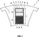
Ein Statorkörper
Die Nut
Weiterhin kann eine erste Nutisolation
Vorzugsweise werden die Steckelemente
In den sich zwischen der ersten Wicklung und dem Luftspalt (rückschlussbereichsfernen Abschnitt) erstreckenden zweiten Abschnitt T2 der Nut
Insbesondere weisen die Spulendrähte
Durch das Vorsehen der verschiedenartigen Wicklungen in dem ersten Abschnitt T1 der Nut
In
In
In
Claims (15)
Translated fromGermanPriority Applications (2)
| Application Number | Priority Date | Filing Date | Title |
|---|---|---|---|
| DE102013212909.2ADE102013212909A1 (en) | 2013-07-02 | 2013-07-02 | Machine component for a multi-winding electrical machine |
| PCT/EP2014/060767WO2015000639A2 (en) | 2013-07-02 | 2014-05-26 | Machine component for an electric machine with multiple coils |
Applications Claiming Priority (1)
| Application Number | Priority Date | Filing Date | Title |
|---|---|---|---|
| DE102013212909.2ADE102013212909A1 (en) | 2013-07-02 | 2013-07-02 | Machine component for a multi-winding electrical machine |
Publications (1)
| Publication Number | Publication Date |
|---|---|
| DE102013212909A1true DE102013212909A1 (en) | 2015-01-08 |
Family
ID=50896248
Family Applications (1)
| Application Number | Title | Priority Date | Filing Date |
|---|---|---|---|
| DE102013212909.2AWithdrawnDE102013212909A1 (en) | 2013-07-02 | 2013-07-02 | Machine component for a multi-winding electrical machine |
Country Status (2)
| Country | Link |
|---|---|
| DE (1) | DE102013212909A1 (en) |
| WO (1) | WO2015000639A2 (en) |
Cited By (3)
| Publication number | Priority date | Publication date | Assignee | Title |
|---|---|---|---|---|
| DE102017011853A1 (en) | 2017-12-21 | 2018-05-30 | Daimler Ag | Stator tooth, stator tooth segment, stator body and stator |
| DE102019113432A1 (en)* | 2019-05-21 | 2020-11-26 | Dr. Ing. H.C. F. Porsche Aktiengesellschaft | Electric machine stator and electric machine |
| DE102023132712A1 (en)* | 2023-10-05 | 2025-04-10 | GM Global Technology Operations LLC | Drive system with double-wound electric motor and dual inverter configuration |
Families Citing this family (1)
| Publication number | Priority date | Publication date | Assignee | Title |
|---|---|---|---|---|
| DE102016216766A1 (en)* | 2016-09-05 | 2018-03-29 | Thyssenkrupp Ag | Mounting device for simultaneous insertion and method |
Family Cites Families (6)
| Publication number | Priority date | Publication date | Assignee | Title |
|---|---|---|---|---|
| DE316944C (en)* | 1917-05-17 | 1919-12-08 | ||
| JP2002142416A (en)* | 2000-11-06 | 2002-05-17 | Matsushita Electric Ind Co Ltd | Method for manufacturing stator of electric motor and hermetic compressor |
| DE102006047975A1 (en)* | 2006-10-10 | 2008-04-17 | Siemens Ag | Permanent magnet synchronous machine with flat wire winding |
| US7830062B2 (en)* | 2006-12-12 | 2010-11-09 | Nidec Corporation | Motor having round and angular coils |
| US8310123B2 (en)* | 2008-07-28 | 2012-11-13 | Direct Drive Systems, Inc. | Wrapped rotor sleeve for an electric machine |
| CN103959609A (en)* | 2011-10-27 | 2014-07-30 | 丰田自动车株式会社 | Coil segments, method for manufacturing coil segments, wire rod for coil segments, and stator |
- 2013
- 2013-07-02DEDE102013212909.2Apatent/DE102013212909A1/ennot_activeWithdrawn
- 2014
- 2014-05-26WOPCT/EP2014/060767patent/WO2015000639A2/enactiveApplication Filing
Cited By (4)
| Publication number | Priority date | Publication date | Assignee | Title |
|---|---|---|---|---|
| DE102017011853A1 (en) | 2017-12-21 | 2018-05-30 | Daimler Ag | Stator tooth, stator tooth segment, stator body and stator |
| DE102019113432A1 (en)* | 2019-05-21 | 2020-11-26 | Dr. Ing. H.C. F. Porsche Aktiengesellschaft | Electric machine stator and electric machine |
| DE102023132712A1 (en)* | 2023-10-05 | 2025-04-10 | GM Global Technology Operations LLC | Drive system with double-wound electric motor and dual inverter configuration |
| DE102023132712B4 (en)* | 2023-10-05 | 2025-05-15 | GM Global Technology Operations LLC | Drive system with double-wound electric motor and dual inverter configuration |
Also Published As
| Publication number | Publication date |
|---|---|
| WO2015000639A2 (en) | 2015-01-08 |
| WO2015000639A3 (en) | 2015-06-18 |
Similar Documents
| Publication | Publication Date | Title |
|---|---|---|
| DE102009032882B3 (en) | Method for producing preformed coil for floor winding of dynamo-electric machine using raw coil, involves bending longitudinal sides around specific degrees such that end winding sides are bent at angle from longitudinal sides | |
| WO2016075215A1 (en) | Wave winding having a low cogging torque, stator and electric machine comprising a wave winding of said type | |
| DE112013001755T5 (en) | Rotating electrical machine | |
| DE102015222367A1 (en) | Wave winding with winding scheme for reducing the voltage differences in a stator of an electric machine | |
| EP3142228A1 (en) | Stator for an electric machine, electric machine and manufacturing method | |
| DE102018111119A1 (en) | Method for producing a winding for a stator of an electrical machine and electric machine | |
| DE102004044986A1 (en) | Permanent magnet synchronous machine with flat wire windings | |
| DE102018207231A1 (en) | Stator for an electric machine, electric machine and manufacturing method for a stator for an electric machine | |
| DE102016102234B4 (en) | METHOD OF ARRANGEMENT OF THE WINDINGS FOR A DISTRIBUTED WINDING RADIAL SPLIT MOTOR | |
| DE102012214523B4 (en) | Stator or stator segment of a dynamo-electric machine with an optimized end winding, dynamo-electric machine and tube mill or wind power generator | |
| EP3352341B1 (en) | Stator and method for manufacturing a stator | |
| DE102013212909A1 (en) | Machine component for a multi-winding electrical machine | |
| EP1915812B1 (en) | Electric machine with a multi-level winding | |
| DE102020109482B4 (en) | A method for producing a stator for an electrical machine, a corresponding stator and a method for operating an electrical machine, a corresponding stator and a method for operating an electrical machine | |
| DE202009008515U1 (en) | Stator for an electric motor | |
| EP3167540B1 (en) | Method for producing an electrical machine using pre-formed coils and electrical machine and production tool | |
| WO2016096246A1 (en) | Winding arrangement and electric machine with a winding arrangement of this type | |
| DE102013216210A1 (en) | Winding body for a stator of an electric motor | |
| EP2680414B1 (en) | Method for manufacturing a coil for the generator of a wind turbine | |
| DE102020115521A1 (en) | Stator for an electrical machine, as well as an electrical machine | |
| DE102009001543A1 (en) | Electric machine and method for manufacturing an electric machine | |
| DE10061045A1 (en) | Multi-phase electrical machine | |
| DE102014222942A1 (en) | Stator of an electric machine | |
| EP3534514A1 (en) | Coil winding for a stator of a rotating electrical machine | |
| DE102023205305A1 (en) | Distributed winding for an electrical machine |
Legal Events
| Date | Code | Title | Description |
|---|---|---|---|
| R119 | Application deemed withdrawn, or ip right lapsed, due to non-payment of renewal fee |