DE102013212036A1 - Structure section for a vehicle - Google Patents
Structure section for a vehicleDownload PDFInfo
- Publication number
- DE102013212036A1 DE102013212036A1DE102013212036.2ADE102013212036ADE102013212036A1DE 102013212036 A1DE102013212036 A1DE 102013212036A1DE 102013212036 ADE102013212036 ADE 102013212036ADE 102013212036 A1DE102013212036 A1DE 102013212036A1
- Authority
- DE
- Germany
- Prior art keywords
- resistance
- section
- resistance line
- vehicle
- structure section
- Prior art date
- Legal status (The legal status is an assumption and is not a legal conclusion. Google has not performed a legal analysis and makes no representation as to the accuracy of the status listed.)
- Pending
Links
- 239000002131composite materialSubstances0.000claimsabstractdescription14
- 239000000835fiberSubstances0.000claimsabstractdescription14
- 239000000463materialSubstances0.000claimsdescription10
- 239000011159matrix materialSubstances0.000claimsdescription10
- 238000003466weldingMethods0.000claimsdescription10
- 238000002405diagnostic procedureMethods0.000claimsdescription6
- 239000004744fabricSubstances0.000claimsdescription3
- 238000003745diagnosisMethods0.000description9
- 238000000034methodMethods0.000description9
- 230000000875corresponding effectEffects0.000description7
- 238000001514detection methodMethods0.000description5
- 238000004519manufacturing processMethods0.000description5
- 238000002844meltingMethods0.000description3
- 230000008018meltingEffects0.000description3
- 238000012549trainingMethods0.000description3
- 238000001816coolingMethods0.000description2
- 230000002950deficientEffects0.000description2
- 230000001419dependent effectEffects0.000description2
- 238000010438heat treatmentMethods0.000description2
- 238000005304joiningMethods0.000description2
- 238000012544monitoring processMethods0.000description2
- 239000012815thermoplastic materialSubstances0.000description2
- 229920000049Carbon (fiber)Polymers0.000description1
- 239000000853adhesiveSubstances0.000description1
- 238000004026adhesive bondingMethods0.000description1
- 230000001070adhesive effectEffects0.000description1
- 239000004917carbon fiberSubstances0.000description1
- 239000004918carbon fiber reinforced polymerSubstances0.000description1
- 238000004891communicationMethods0.000description1
- 150000001875compoundsChemical class0.000description1
- 230000002596correlated effectEffects0.000description1
- 238000005336crackingMethods0.000description1
- 230000007547defectEffects0.000description1
- 230000032798delaminationEffects0.000description1
- 238000013461designMethods0.000description1
- 239000002657fibrous materialSubstances0.000description1
- 230000009969flowable effectEffects0.000description1
- 239000012530fluidSubstances0.000description1
- 238000007710freezingMethods0.000description1
- 230000008014freezingEffects0.000description1
- 239000003365glass fiberSubstances0.000description1
- 230000001771impaired effectEffects0.000description1
- 238000003780insertionMethods0.000description1
- 230000037431insertionEffects0.000description1
- 238000005259measurementMethods0.000description1
- VNWKTOKETHGBQD-UHFFFAOYSA-NmethaneChemical compoundCVNWKTOKETHGBQD-UHFFFAOYSA-N0.000description1
- 238000000275quality assuranceMethods0.000description1
- 238000003908quality control methodMethods0.000description1
- 238000004088simulationMethods0.000description1
- 229920001169thermoplasticPolymers0.000description1
- 239000004416thermosoftening plasticSubstances0.000description1
- 238000011179visual inspectionMethods0.000description1
- 239000013585weight reducing agentSubstances0.000description1
Images


Classifications
- G—PHYSICS
- G01—MEASURING; TESTING
- G01M—TESTING STATIC OR DYNAMIC BALANCE OF MACHINES OR STRUCTURES; TESTING OF STRUCTURES OR APPARATUS, NOT OTHERWISE PROVIDED FOR
- G01M5/00—Investigating the elasticity of structures, e.g. deflection of bridges or air-craft wings
- G01M5/0033—Investigating the elasticity of structures, e.g. deflection of bridges or air-craft wings by determining damage, crack or wear
- B—PERFORMING OPERATIONS; TRANSPORTING
- B62—LAND VEHICLES FOR TRAVELLING OTHERWISE THAN ON RAILS
- B62D—MOTOR VEHICLES; TRAILERS
- B62D25/00—Superstructure or monocoque structure sub-units; Parts or details thereof not otherwise provided for
- B62D25/06—Fixed roofs
- B—PERFORMING OPERATIONS; TRANSPORTING
- B62—LAND VEHICLES FOR TRAVELLING OTHERWISE THAN ON RAILS
- B62D—MOTOR VEHICLES; TRAILERS
- B62D29/00—Superstructures, understructures, or sub-units thereof, characterised by the material thereof
- B62D29/04—Superstructures, understructures, or sub-units thereof, characterised by the material thereof predominantly of synthetic material
- G—PHYSICS
- G01—MEASURING; TESTING
- G01M—TESTING STATIC OR DYNAMIC BALANCE OF MACHINES OR STRUCTURES; TESTING OF STRUCTURES OR APPARATUS, NOT OTHERWISE PROVIDED FOR
- G01M5/00—Investigating the elasticity of structures, e.g. deflection of bridges or air-craft wings
- G01M5/0083—Investigating the elasticity of structures, e.g. deflection of bridges or air-craft wings by measuring variation of impedance, e.g. resistance, capacitance, induction
Landscapes
- Engineering & Computer Science (AREA)
- Aviation & Aerospace Engineering (AREA)
- Physics & Mathematics (AREA)
- General Physics & Mathematics (AREA)
- Chemical & Material Sciences (AREA)
- Combustion & Propulsion (AREA)
- Transportation (AREA)
- Mechanical Engineering (AREA)
- Architecture (AREA)
- Structural Engineering (AREA)
- Body Structure For Vehicles (AREA)
Abstract
Translated fromGermanDescription
Translated fromGermanDie vorliegende Erfindung betrifft einen Strukturabschnitt für ein Fahrzeug, ein Fahrzeug mit einer mechanisch belastbaren Fahrzeugstruktur sowie ein Diagnoseverfahren für die Erkennung einer Beschädigung eines Strukturabschnitts.The present invention relates to a structural portion for a vehicle, a vehicle having a mechanically loadable vehicle structure and a diagnostic method for detecting damage of a structural portion.
Grundsätzlich ist es bekannt, dass Fahrzeuge Strukturabschnitte aufweisen, um mechanische Belastungen des Fahrzeugs aufnehmen zu können. Dabei handelt es sich zum Beispiel um Strukturabschnitte der Karosserie oder des Chassis. Weiter ist es bereits bekannt, dass diese Strukturabschnitte aus einzelnen Bauteilen zusammengesetzt werden. Dabei werden unterschiedlichste Fügeverfahren verwendet, um eine kraftschlüssige Verbindung zwischen den einzelnen Bauteilen zu erzielen. Bei modernen Fahrzeugen ist Gewichtsreduktion eine entscheidende Aufgabe. Dementsprechend wird bei bekannten Fahrzeugen vermehrt der Einsatz von Faserverbundmaterialien gefordert. Eine Verbindung von Bauteilen aus Faserverbundmaterialien kann zum Beispiel durch Verkleben oder Verschweißen zur Verfügung gestellt werden.In principle, it is known that vehicles have structural sections in order to be able to absorb mechanical loads on the vehicle. These are, for example, structural sections of the body or the chassis. Furthermore, it is already known that these structural sections are composed of individual components. A variety of joining methods are used to achieve a positive connection between the individual components. In modern vehicles, weight reduction is a crucial task. Accordingly, the use of fiber composite materials is increasingly required in known vehicles. A connection of components made of fiber composite materials can be provided for example by gluing or welding.
Nachteilhaft bei bekannten Strukturabschnitten von Fahrzeugen, insbesondere bei solchen mit Bauteilen mit Faserverbundmaterialien, ist es, dass neue Beschädigungsarten bei Faserverbundmaterialien bestehen. So ist es beispielsweise möglich, dass einzelne Fasern oder Faserbereiche in den Bauteilen brechen. Auch kann im Bereich des Verbindungsabschnitts zwischen den beiden Bauteilen eine sogenannte Delamination stattfinden, also ein Ablösen einzelner Laminatschichten voneinander. Entscheidend dabei ist jedoch, dass solche Schadenssituationen häufig nicht von der Außenseite des jeweiligen Bauteils bzw. von der Außenseite des Strukturabschnitts des Fahrzeugs erkennbar sind. So können mechanische Beeinflussungen, zum Beispiel bei einer Crash-Situation oder bei kleineren Parkremplern beim Fahrzeug, dazu führen, dass an den Verbindungsstellen Fehlstellen entstehen.A disadvantage of known structural sections of vehicles, especially those with components with fiber composite materials, is that there are new types of damage in fiber composite materials. For example, it is possible for individual fibers or fiber regions to break in the components. Also, in the region of the connecting portion between the two components, a so-called delamination can take place, that is, detachment of individual laminate layers from one another. Decisive here, however, is that such damage situations are often not recognizable from the outside of the respective component or from the outside of the structural portion of the vehicle. Thus, mechanical influences, for example in the event of a crash situation or in the case of smaller parking bumps on the vehicle, can lead to defects at the connection points.
Es ist Aufgabe der vorliegenden Erfindung, die voranstehend beschriebenen Nachteile zumindest teilweise zu beheben. Insbesondere ist es Aufgabe der vorliegenden Erfindung, in kostengünstiger und einfacher Weise eine Diagnostizierung von Schadstellen innerhalb eines Strukturabschnitts gewährleisten zu können.It is an object of the present invention to at least partially overcome the disadvantages described above. In particular, it is the object of the present invention to be able to ensure diagnostics of damaged areas within a structural section in a cost-effective and simple manner.
Voranstehende Aufgabe wird gelöst durch einen Strukturabschnitt mit den Merkmalen des Anspruchs 1, ein Fahrzeug mit den Merkmalen des Anspruchs 8 sowie ein Diagnoseverfahren mit den Merkmalen des Anspruchs 9. Weitere Merkmale und Details der Erfindung ergeben sich aus den Unteransprüchen, der Beschreibung und den Zeichnungen. Dabei gelten Merkmale und Details, die im Zusammenhang mit dem erfindungsgemäßen Strukturabschnitt beschrieben sind, selbstverständlich auch im Zusammenhang mit dem erfindungsgemäßen Fahrzeug sowie dem erfindungsgemäßen Diagnoseverfahren und jeweils umgekehrt, sodass bezüglich der Offenbarung zu den einzelnen Erfindungsaspekten stets wechselseitig Bezug genommen wird beziehungsweise werden kann.The above object is achieved by a structural portion having the features of claim 1, a vehicle having the features of claim 8 and a diagnostic method having the features of claim 9. Further features and details of the invention will become apparent from the dependent claims, the description and the drawings. In this case, features and details that are described in connection with the structure section according to the invention apply, of course, in connection with the vehicle according to the invention and the diagnostic method according to the invention and in each case vice versa, so that with respect to the disclosure of the individual aspects of the invention always reciprocal reference is or may be.
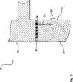
Bei einem erfindungsgemäßen Strukturabschnitt für ein Fahrzeug ist dieses mit einem ersten Bauteil aus Faserverbundmaterial und einem zweiten Bauteil aus Faserverbundmaterial ausgestattet. Die beiden Bauteile sind miteinander über einen Verbindungsabschnitt verbunden. Der erfindungsgemäße Strukturabschnitt zeichnet sich dadurch aus, dass im Verbindungsabschnitt wenigstens eine bestrombare elektrische Widerstandsleitung angeordnet ist. Unter einem Strukturabschnitt ist insbesondere ein Abschnitt der Karosserie oder des Chassis des Fahrzeugs zu verstehen. Auch andere mechanisch belastete Bauteile, zum Beispiel aus dem Innenraum des Fahrzeugs, sind als Strukturabschnitt des Fahrzeugs zu bezeichnen.In a structural part according to the invention for a vehicle, this is equipped with a first component made of fiber composite material and a second component made of fiber composite material. The two components are connected to each other via a connecting portion. The structure section according to the invention is characterized in that at least one refuelable electrical resistance line is arranged in the connection section. A structural section is to be understood in particular as a section of the body or chassis of the vehicle. Other mechanically loaded components, for example, from the interior of the vehicle, are referred to as a structural portion of the vehicle.
Unter einem Verbindungsabschnitt ist insbesondere der Bereich zu verstehen, welcher sich in verbindender Weise durch die Kontaktflächen der beiden Bauteile miteinander ausbildet. So ist der Verbindungsabschnitt hinsichtlich seiner Struktur in seiner Erstreckung abhängig von der Geometrie der beiden Bauteile sowie von der Art des Verbindungsverfahrens. Sind die beiden Bauteile zum Beispiel mit einer Matrix aus thermoplastischem Material ausgestattet, so können die Kontaktflächen der beiden Bauteile aneinander gebracht und anschließend die Matrix aufgeschmolzen werden. Das Aufschmelzen führt dazu, dass sozusagen das Matrixmaterial der beiden aneinander grenzenden Bauteile sich miteinander vermischt und somit eine Materialeinheit, also einen Stoffschluss, eingeht. Um ein solches Materialschweißverfahren für die Verbindung der beiden Bauteile zur Verfügung zu stellen, kann beispielsweise ebenfalls die erfindungsgemäß vorzusehende elektrische Widerstandsleitung Verwendung finden. Sie dient in diesem Fall dazu, sich über Bestromung aufzuheizen und damit ein Aufschmelzen des Matrixmaterials der beiden Bauteile zu erzielen. Somit wird sozusagen eine Funktionsunion der Widerstandsleitung erzielbar. Diese wird zum einen für die Herstellung der Verbindung mittels eines Schweißverfahrens und zum anderen für die Diagnostik von Schadsituationen im Verbindungsabschnitt zur Verfügung gestellt.A connection section is to be understood in particular as the area which forms in a connecting manner through the contact surfaces of the two components with one another. Thus, the connecting portion is in terms of its structure in its extension dependent on the geometry of the two components and the nature of the connection method. If the two components are equipped, for example, with a matrix of thermoplastic material, the contact surfaces of the two components can be brought together and then the matrix can be melted. The melting leads to the fact that so to speak, the matrix material of the two adjacent components mixed together and thus a material unit, ie a material bond, received. In order to provide such a material welding method for the connection of the two components, the electrical resistance line to be provided according to the invention can also be used, for example. In this case, it serves to heat up via current supply and thus to achieve a melting of the matrix material of the two components. Thus, as it were, a functional union of the resistance line can be achieved. This is provided on the one hand for the production of the connection by means of a welding process and on the other hand for the diagnosis of damage situations in the connecting section.
Ein erfindungsgemäßer Strukturabschnitt ist, wie bereits erläutert worden ist, mit wenigstens einer bestrombaren elektrischen Widerstandsleitung ausgestattet. Diese kann bestromt und dementsprechend der sich einstellende elektrische Widerstand bestimmt werden. Der bestimmte Widerstand hängt dabei von der mechanischen Belastungssituation der Widerstandsleitung ab. So kann die Widerstandsleitung zum Beispiel durch extreme mechanische Belastungen des Strukturabschnitts verformt und mechanisch beeinträchtigt werden. Dies führt zum Beispiel zu einer Reduktion des Querschnitts der Widerstandsleitung durch einen Teilbruch. Dies führt wiederum zu einem veränderten, insbesondere einem erhöhten, Widerstandswert bei der Bestromung der Widerstandsleitung. Erfolgt eine noch stärkere mechanische Beeinflussung des Strukturabschnitts, so kann es zum vollständigen Reißen oder Bruch der Widerstandsleitung kommen. Dies wird durch einen sozusagen unendlich großen Widerstand bei der Bestromung dieser Widerstandsleitung erkennbar. Aufgrund der Tatsache, dass der Ort der Anbringung der Widerstandsleitung bekannt ist, kann dementsprechend durch den Vergleich des gemessenen Widerstandswerts mit einem Soll-Wert für diesen Widerstandswert die Intaktheit der Widerstandsleitung bestimmt werden. Mögliche mechanische Beeinflussungen werden dementsprechend indirekt diagnostizierbar. Die Widerstandsleitung wird dabei bereits während der Fertigung zwischen die beiden Bauteile in den Verbindungsabschnitt eingebracht.As already explained, a structural section according to the invention is equipped with at least one current-carrying electrical resistance line. This can be energized and accordingly the adjusting electrical resistance be determined. The specific resistance depends on the mechanical load situation of the resistance line. For example, the resistance line can be deformed and mechanically impaired by extreme mechanical loads on the structural section. This leads for example to a reduction of the cross section of the resistance line by a partial break. This in turn leads to an altered, in particular an increased, resistance value during the energization of the resistance line. If there is an even stronger mechanical influence on the structural section, it can lead to the complete cracking or breakage of the resistance line. This can be seen by a so-called infinite resistance during the energization of this resistance line. Accordingly, by virtue of the fact that the location of the resistance line attachment is known, the integrity of the resistance line can be determined by comparing the measured resistance value with a desired value for that resistance value. Possible mechanical influences are accordingly indirectly diagnosable. The resistance line is already introduced during manufacture between the two components in the connecting portion.
In erfindungsgemäßer Weise kann eine solche Diagnose sowohl im Einsatz als auch während der Fertigung Verwendung finden. So kann beispielsweise direkt nach dem Erzeugen der Verbindung im Verbindungsabschnitt eine qualitätssichernde Maßnahme in erfindungsgemäßer Weise durchgeführt werden. So wird durch Bestromung der Widerstandsleitung festgestellt, ob möglicherweise eine Beschädigung der Widerstandsleitung und dementsprechend eine Schadstelle innerhalb des Verbindungsabschnitts vorliegt. Insbesondere kann bei einem erfindungsgemäßen Strukturabschnitt jedoch bei Crash-Situationen im Anschluss eine Diagnose des Fahrzeugs stattfinden. Damit kann durch veränderte Widerstandswerte einzelner Widerstandsleitungen eine mögliche Schadstelle nicht nur einem Strukturabschnitt eines Fahrzeugs, sondern sogar exakt einem Ort innerhalb des Strukturabschnitt des Fahrzeugs zugewiesen werden.In accordance with the invention, such a diagnosis can be used both during use and during manufacture. Thus, for example, directly after the connection has been produced in the connecting section, a quality assurance measure can be carried out in accordance with the invention. Thus, it is determined by energizing the resistance line whether there is possibly damage to the resistance line and, accordingly, a damaged area within the connection section. In particular, however, in the case of a structural section according to the invention, a diagnosis of the vehicle may subsequently take place in crash situations. Thus, by changing the resistance values of individual resistance lines, a possible damaged area can be assigned not only to a structural section of a vehicle, but even exactly to a location within the structural section of the vehicle.
Unter Faserverbundmaterial ist im Sinne der vorliegenden Erfindung zum Beispiel Glasfaserverbund oder Kohlefaserverbund (GFK oder CFK) zu verstehen. Selbstverständlich sind auch sämtliche andere Kombinationen aus Fasermaterialien und fließfähig einbringbaren Matrixmaterialien denkbar.For the purposes of the present invention, fiber composite material is understood, for example, as glass fiber composite or carbon fiber composite (GRP or CFRP). Of course, all other combinations of fiber materials and flowable matrix materials are conceivable.
Als Verbindung wurde als Beispiel ein Schweißverfahren beschrieben. Selbstverständlich sind jedoch auch andere Verbindungsarten, insbesondere das Durchführen von Kleberverbindungen, im Sinne der vorliegenden Erfindung möglich.As a connection, a welding method has been described as an example. Of course, however, other types of connections, in particular the implementation of adhesive compounds, in the context of the present invention possible.
Erfindungsgemäß werden insbesondere mehr als eine Widerstandsleitung, also zwei oder mehrere Widerstandsleitungen, im Verbindungsabschnitt angeordnet. Die Bestromung und die Erkennung des Widerstands der jeweiligen Widerstandsleitung erfolgt vorzugsweise spezifisch für jede einzelne Widerstandsleitung, um eine entsprechende Ortszugehörigkeit des bestimmten Parameters erzielen zu können.According to the invention, in particular more than one resistance line, that is, two or more resistance lines, are arranged in the connection section. The energization and the detection of the resistance of the respective resistance line is preferably carried out specifically for each individual resistance line in order to achieve a corresponding location affiliation of the particular parameter.
Neben der Diagnostik ist ein entscheidender Vorteil einer erfindungsgemäßen Ausbildung des Strukturabschnitts, dass derselbe nur dann nach einem Crash ausgetauscht werden muss, wenn auch tatsächlich eine Schadstelle bestimmt wird. Bei einem Crash möglicherweise innerhalb des Materials beschädigte Strukturabschnitte, welche durch eine Sichtprüfung als unbeschädigt gelten würden, können durch eine erfindungsgemäße Diagnose ebenfalls als schadhaft erkannt werden. Möglicherweise bestehende Restrisiken für nachfolgende Crash-Situationen durch reduzierte mechanische Belastbarkeit des jeweiligen Strukturabschnitts werden auf diese Weise vermieden.In addition to diagnostics, a decisive advantage of an embodiment of the structural section according to the invention is that it only has to be replaced after a crash, even if a damaged area is actually determined. In a crash possibly damaged within the material structure sections, which would be considered by a visual inspection as undamaged, can also be recognized as defective by a diagnosis according to the invention. Possibly existing residual risks for subsequent crash situations due to reduced mechanical strength of the respective structural section are avoided in this way.
Selbstverständlich kann die Widerstandsleitung entsprechende Anschlüsse aufweisen, um insbesondere ständig ein erfindungsgemäßes Diagnoseverfahren, wie es später noch erläutert wird, durchzuführen.Of course, the resistance line can have corresponding connections in order, in particular, to constantly carry out a diagnostic method according to the invention, as will be explained later.
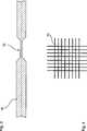
Es kann von Vorteil sein, wenn bei einem erfindungsgemäßen Strukturabschnitt mehrere Widerstandsleitungen vorgesehen sind, welche als Netzwerk, insbesondere als Gewebe ausgebildet sind. Ein Netzwerk bedeutet, dass eine explizite örtliche Korrelation zwischen den einzelnen Widerstandsleitungen besteht. Unter einem Gewebe sind dabei unterschiedliche Erstreckungsrichtungen der einzelnen Widerstandsleitungen zu verstehen. Insbesondere kreuzen sich einzelne Widerstandsleitungen, sodass sozusagen eine zweidimensionale Erstreckung für die Widerstandsmessung zur Verfügung gestellt werden kann. Dies führt zu einer genaueren Überwachung und vor allem zu einer örtlich noch höher auflösenden Diagnostik hinsichtlich der Erkennung veränderter Widerstandswerte und dementsprechend hinsichtlich der indirekten Erkennung von möglichen Schadstellen im Strukturabschnitt.It may be advantageous if, in a structure section according to the invention, a plurality of resistance lines are provided, which are formed as a network, in particular as a fabric. A network means that there is an explicit local correlation between the individual resistance lines. Under a tissue are different directions of extension of the individual resistance lines to understand. In particular, individual resistance lines intersect, so that as it were a two-dimensional extent for the resistance measurement can be provided. This leads to a more precise monitoring and above all to a locally even higher resolution diagnostics with regard to the detection of changed resistance values and accordingly with regard to the indirect detection of possible damage sites in the structural section.
Ein erfindungsgemäßer Strukturabschnitt lässt sich dahingehend weiterbilden, dass mehrere Widerstandsleitungen vorgesehen sind, welche im Bereich der höchsten im Einsatz zu erwartenden Belastung des Strukturabschnitts angeordnet sind. So kann zum Beispiel durch digitale Simulation (FEM-Analyse) eine Belastungssituation des Strukturabschnitts im Einsatz simuliert werden. Einzelne Abschnitte der Bauteile, insbesondere des Verbindungsabschnittes, können höhere zu erwartende Belastungen aufweisen als andere Abschnitte. Gerade dieser Bereich wird hinsichtlich mechanischer Belastungen und entsprechend induzierter schadhafter Stellen von größtem Risiko behaftet sein. Das Anordnen entsprechender Widerstandsleitungen gerade in diesem Risikobereich führt dazu, dass eine fokussierte Auflösung der Diagnostik möglich wird. Damit wird die Widerstandsleitung ausschließlich in dem Bereich eingesetzt bzw. verdichtet in dem Bereich eingesetzt, welcher ein hohes Risiko hinsichtlich Schadstellen mit sich bringt. Damit können Kosten reduziert werden und weniger risikobehaftete Bereiche nur weniger eng bzw. überhaupt nicht überwacht werden. Dies führt neben reduzierten Kosten auch zu weniger Aufwand und weniger Gewicht des gesamten Strukturabschnitts.A structure section according to the invention can be further developed such that a plurality of resistance lines are provided which are arranged in the region of the highest load of the structure section to be expected in use. For example, by digital simulation (FEM analysis) a load situation of the structural section can be simulated in use. Individual sections of the components, in particular the connecting section, can be expected higher Have loads than other sections. It is precisely this area that is subject to the greatest risk with regard to mechanical loads and correspondingly induced defective locations. Arranging corresponding resistance lines precisely in this risk area leads to a focused resolution of the diagnostics. Thus, the resistance line is used exclusively in the area or compressed in the area used, which brings with it a high risk of damage. This can reduce costs and less risky areas are less closely or not at all monitored. In addition to reduced costs, this also leads to less effort and less weight of the entire structure section.
Vorteilhaft ist es weiter, wenn bei einem erfindungsgemäßen Strukturabschnitt der Verbindungsabschnitt in Form eines Schweißabschnitts mit dem Material der Matrix wenigstens eines der beiden Bauteile ausgebildet ist. Dafür weist eines oder sogar beide der beiden Bauteile ein aufschmelzbares Material als Matrixmaterial auf. Dabei kann es sich zum Beispiel um ein thermoplastisches Material handeln. Wie bereits angedeutet worden ist, kann die erfindungsgemäß eingesetzte Widerstandsleitung hier als zusätzliche Funktion auch den Schweißprozess durchführen. So wird vor dem Zusammenfügen der beiden Bauteile die Anzahl der Widerstandsleitungen in den Verbindungsabschnitt eingelegt und nach dem Zusammensetzen diese Widerstandsleitungen bestromt. Durch den Widerstand wird ein Aufheizen der Widerstandsleitungen und damit des umgebenden Matrixmaterials erzeugt. Dieses wird fließfähig und bildet einen Stoffschluss zwischen den beiden Bauteilen aus, sobald ein Erkalten und somit ein Erstarren stattgefunden hat.It is furthermore advantageous if, in the case of a structural section according to the invention, the connecting section is designed in the form of a welding section with the material of the matrix of at least one of the two components. For this purpose, one or even both of the two components have a meltable material as the matrix material. This may be, for example, a thermoplastic material. As has already been indicated, the resistance line used according to the invention can also perform the welding process here as an additional function. Thus, before the joining of the two components, the number of resistance lines is inserted into the connecting portion and energized after assembly of these resistance lines. The resistor generates a heating of the resistance lines and thus of the surrounding matrix material. This becomes fluid and forms a material bond between the two components as soon as a cooling and thus a freezing has taken place.
Ebenfalls von Vorteil kann es sein, wenn bei einem erfindungsgemäßen Strukturabschnitt die Widerstandsleitung mit Sollbruchstellen für den Bruch der Widerstandsleitung bei einer definierten mechanischen Beeinflussung ausgebildet ist. Sollbruchstellen sind als mechanische Sollbruchstellen ausgebildet und dienen dazu, an definierter Stelle und insbesondere auch bei definierter mechanischer Belastung zu brechen. Dies führt dazu, dass im Nachhinein beim Erkennen eines im Wesentlichen unendlichen Widerstands ein Bruch der Sollbruchstellen erkannt werden kann. Ein Bruch der Sollbruchstellen steht für eine explizite Belastungssituation, welche oberhalb der für die Sollbruchstelle definierten Belastungssituation lag. So kann über die Ausbildung und die Anordnung der Sollbruchstellen eine zusätzliche Absicherung hinsichtlich der Diagnostik von Schadstellen erzielt werden. Insbesondere wird es möglich, auch bei komplexen Crash-Situationen sicherzustellen, dass mögliche Schadstellen durch eine erfindungsgemäße Diagnostik erkennbar werden.It may also be advantageous if, in a structural section according to the invention, the resistance line is designed with predetermined breaking points for the breakage of the resistance line with a defined mechanical influence. Predetermined breaking points are designed as mechanical predetermined breaking points and serve to break at a defined point and in particular also at a defined mechanical load. As a result, a break in the predetermined breaking points can be recognized in retrospect on detection of a substantially infinite resistance. A break of the predetermined breaking points stands for an explicit load situation, which was above the load situation defined for the predetermined breaking point. Thus, on the training and the arrangement of the predetermined breaking points an additional safeguard can be achieved with regard to the diagnosis of damaged areas. In particular, it becomes possible to ensure, even in the case of complex crash situations, that possible damaged areas can be detected by a diagnostics according to the invention.
Vorteilhaft ist es ebenfalls, wenn bei einem erfindungsgemäßen Strukturabschnitt elektrische Schnittstellen der Widerstandsleitung an der Außenfläche des Strukturabschnitts angeordnet sind. Diese sind insbesondere einfache Steckkontakte, um ein Auslesen der gemessenen Widerstandswerte zur Verfügung zu stellen. Auch können die elektrischen Schnittstellen direkt für die Bestromung der Widerstandsleitung ausgebildet sein. So kann beispielsweise ein externes Diagnosegerät an diesen elektrischen Schnittstellen angeschlossen werden. Auch ist es möglich, dass eine Kontrollvorrichtung des Fahrzeugs in ständigem Kontakt mit den elektrischen Schnittstellen steht, um anschließend beim Auslesen des Fahrzeug-Steuergeräts die entsprechende Bestromung der Widerstandsleitungen durchführen zu können. Auch kann über diese elektrischen Schnittstellen eine quasi kontinuierliche oder in definierten Zeitspannen durchgeführte Diagnose zur Verfügung gestellt werden.It is likewise advantageous if, in the case of a structure section according to the invention, electrical interfaces of the resistance line are arranged on the outer surface of the structure section. These are in particular simple plug-in contacts in order to provide readout of the measured resistance values. Also, the electrical interfaces can be designed directly for the energization of the resistance line. For example, an external diagnostic device can be connected to these electrical interfaces. It is also possible for a control device of the vehicle to be in constant contact with the electrical interfaces in order subsequently to be able to carry out the corresponding energization of the resistance lines when reading out the vehicle control unit. Also, a quasi-continuous or performed in defined periods diagnosis can be provided via these electrical interfaces.
Vorteilhaft ist es weiter, wenn bei einem erfindungsgemäßen Strukturabschnitt isolierte elektrische Leitungen zu der wenigstens einen Widerstandsleitung in wenigstens einem der beiden Bauteile, insbesondere in leitender Verbindung mit elektrischen Schnittstellen an der Außenfläche des Strukturabschnitts, angeordnet sind. Damit wird die Positionierbarkeit der Widerstandsleitungen noch freier. So kann auch an versteckten Positionen zwischen zwei Bauteilen eine erfindungsgemäße Ausbildung durch das Einlegen von Widerstandsleitungen zur Verfügung gestellt werden. Um elektrische Schnittstellen an besonders gut zugänglichen Bereichen für entsprechende Steckkontakte anordnen zu können, kann eine isolierte elektrische Leitung eine entsprechende Überbrückung der örtlichen Distanz gewährleisten. Die isolierte elektrische Leitung dient dabei auch der Bestromung und ist insbesondere unabhängig von mechanischen Beeinflussungen des Strukturabschnitts verlegt. Damit kann bei der Herstellung des Strukturabschnitts einen elektrische Leitung in isolierter Weise bereits in das jeweilige Bauteil eingebraucht werden.It is furthermore advantageous if, in a structural section according to the invention, insulated electrical lines are arranged to the at least one resistance line in at least one of the two components, in particular in conductive connection with electrical interfaces on the outer surface of the structure section. This makes the positionability of the resistance lines even more free. Thus, a training according to the invention by the insertion of resistance lines can be made available at hidden positions between two components. In order to be able to arrange electrical interfaces at particularly easily accessible areas for corresponding plug contacts, an insulated electrical line can ensure a corresponding bridging of the local distance. The insulated electrical line also serves to energize and is in particular laid independently of mechanical influences of the structural section. In this way, in the production of the structural section, an electrical line can already be used in an insulated manner in the respective component.
Ein weiterer Gegenstand der vorliegenden Erfindung ist ein Fahrzeug mit einer mechanisch belastbaren Fahrzeugstruktur, aufweisend zumindest einen Strukturabschnitt gemäß der vorliegenden Erfindung. Dabei ist eine Diagnosevorrichtung vorgesehen, für die Bestromung der wenigstens einen Widerstandsleitung und die Bestimmung des Widerstandswerts der wenigstens einen Widerstandsleitung. Ein Widerstandswert ist dabei ein Parameter, zum Beispiel mit der Einheit Ohm, welcher mit einem entsprechenden Vergleichswert vergleichbar ist. Durch die Verwendung einer erfindungsgemäßen Ausbildung des Strukturabschnitts bringt ein erfindungsgemäßes Fahrzeug die gleichen Vorteile mit sich, wie sie ausführlich mit Bezug auf einen erfindungsgemäßen Strukturabschnitt erläutert worden sind.Another object of the present invention is a vehicle having a mechanically loadable vehicle structure, comprising at least one structural section according to the present invention. In this case, a diagnostic device is provided for the energization of the at least one resistance line and the determination of the resistance value of the at least one resistance line. A resistance value is a parameter, for example, with the unit ohm, which is comparable to a corresponding comparison value. By using an inventive design of the structural portion brings a vehicle according to the invention with the same advantages as they have been explained in detail with reference to a structural section according to the invention.
Ebenfalls Gegenstand der vorliegenden Erfindung ist ein Diagnoseverfahren für die Erkennung einer Beschädigung eines Strukturabschnitts gemäß der vorliegenden Erfindung, aufweisend die folgenden Schritte:
- – Bestromung der wenigstens einen Widerstandsleitung des Strukturabschnitts,
- – Erfassen des Widerstandswerts der wenigstens einen Widerstandsleitung,
- – Vergleich des erfassten Widerstandswerts mit einer vordefinierten Grenze.
- Energizing the at least one resistance line of the structure section,
- Detecting the resistance value of the at least one resistance line,
- - Comparison of the detected resistance value with a predefined limit.
Das erfindungsgemäße Diagnoseverfahren kann sowohl direkt nach der Herstellung als Qualitätskontrolle, oder auch später, zum Beispiel nach dem Crash eines Fahrzeugs, durchgeführt werden. Auch kann eine sozusagen kontinuierliche oder ständige Überwachung eines Fahrzeugs hinsichtlich der mechanischen Belastbarkeit einzelner Strukturabschnitte durchgeführt werden. Insbesondere erfolgt der Vergleich mit der vordefinierten Grenze mit Bezug auf ein unbeschädigtes Bauteil.The diagnostic method according to the invention can be carried out both directly after the production as quality control, or also later, for example after the crash of a vehicle. Also, a so-called continuous or constant monitoring of a vehicle with regard to the mechanical load capacity of individual structural sections can be performed. In particular, the comparison is made with the predefined limit with respect to an undamaged component.
Weitere Vorteile, Merkmale und Einzelheiten der Erfindung ergeben sich aus der nachfolgenden Beschreibung, in der unter Bezugnahme auf die Zeichnungen Ausführungsbeispiele der Erfindung im Einzelnen beschrieben sind. Dabei können die in den Ansprüchen und in der Beschreibung erwähnten Merkmale jeweils einzeln für sich oder in beliebiger Kombination erfindungswesentlich sein. Es zeigen schematisch:Further advantages, features and details of the invention will become apparent from the following description in which, with reference to the drawings, embodiments of the invention are described in detail. The features mentioned in the claims and in the description may each be essential to the invention individually or in any desired combination. They show schematically:
In
Wie in der
In
In
Die voranstehende Erläuterung der Ausführungsformen beschreibt die vorliegende Erfindung ausschließlich im Rahmen von Beispielen. Selbstverständlich können einzelne Merkmale der Ausführungsformen, sofern technisch sinnvoll, frei miteinander kombiniert werden, ohne den Rahmen der vorliegenden Erfindung zu verlassen.The above explanation of the embodiments describes the present invention solely by way of example. Of course, individual features of the embodiments, if technically feasible, can be combined freely with one another, without departing from the scope of the present invention.
BezugszeichenlisteLIST OF REFERENCE NUMBERS
- 1010
- Strukturabschnittstructure section
- 1212
- Außenflächeouter surface
- 2020
- erstes Bauteilfirst component
- 3030
- zweites Bauteilsecond component
- 4040
- Verbindungsabschnittconnecting portion
- 5050
- Widerstandsleitungresistance line
- 5252
- SollbruchstellenPredetermined breaking points
- 5454
- elektrische SchnittstellenElectrical Interfaces
- 5656
- isolierte elektrische Leitungeninsulated electrical lines
- 100100
- Fahrzeugvehicle
- 110110
- Diagnosevorrichtungdiagnostic device
Claims (9)
Translated fromGermanPriority Applications (1)
| Application Number | Priority Date | Filing Date | Title |
|---|---|---|---|
| DE102013212036.2ADE102013212036A1 (en) | 2013-06-25 | 2013-06-25 | Structure section for a vehicle |
Applications Claiming Priority (1)
| Application Number | Priority Date | Filing Date | Title |
|---|---|---|---|
| DE102013212036.2ADE102013212036A1 (en) | 2013-06-25 | 2013-06-25 | Structure section for a vehicle |
Publications (1)
| Publication Number | Publication Date |
|---|---|
| DE102013212036A1true DE102013212036A1 (en) | 2015-01-08 |
Family
ID=52106141
Family Applications (1)
| Application Number | Title | Priority Date | Filing Date |
|---|---|---|---|
| DE102013212036.2APendingDE102013212036A1 (en) | 2013-06-25 | 2013-06-25 | Structure section for a vehicle |
Country Status (1)
| Country | Link |
|---|---|
| DE (1) | DE102013212036A1 (en) |
Cited By (2)
| Publication number | Priority date | Publication date | Assignee | Title |
|---|---|---|---|---|
| DE102016202769A1 (en)* | 2016-02-23 | 2017-08-24 | Technische Universität Dresden | Sensor for integral or spatially resolved strain measurement based on pre-damaged carbon fibers |
| DE102019009052A1 (en)* | 2019-12-23 | 2021-06-24 | Daimler Ag | Outer skin component for a vehicle, method for determining a deformation of an outer skin of a vehicle and method for providing an outer skin component for a vehicle |
Citations (1)
| Publication number | Priority date | Publication date | Assignee | Title |
|---|---|---|---|---|
| DE69629466T2 (en)* | 1995-05-26 | 2004-07-08 | Qinetiq Ltd. | COMPOSITES |
- 2013
- 2013-06-25DEDE102013212036.2Apatent/DE102013212036A1/enactivePending
Patent Citations (1)
| Publication number | Priority date | Publication date | Assignee | Title |
|---|---|---|---|---|
| DE69629466T2 (en)* | 1995-05-26 | 2004-07-08 | Qinetiq Ltd. | COMPOSITES |
Cited By (4)
| Publication number | Priority date | Publication date | Assignee | Title |
|---|---|---|---|---|
| DE102016202769A1 (en)* | 2016-02-23 | 2017-08-24 | Technische Universität Dresden | Sensor for integral or spatially resolved strain measurement based on pre-damaged carbon fibers |
| EP3211396A1 (en)* | 2016-02-23 | 2017-08-30 | Technische Universität Dresden | Sensor for integral or spatially resolved measuring of extensions based on pre-damaged carbon fibres |
| DE102016202769B4 (en) | 2016-02-23 | 2022-09-15 | Technische Universität Dresden | Sensor for the integral or spatially resolved measurement of strains based on pre-damaged carbon fibers |
| DE102019009052A1 (en)* | 2019-12-23 | 2021-06-24 | Daimler Ag | Outer skin component for a vehicle, method for determining a deformation of an outer skin of a vehicle and method for providing an outer skin component for a vehicle |
Similar Documents
| Publication | Publication Date | Title |
|---|---|---|
| EP2603430B1 (en) | Planking panel for a structural component, flow body comprising such a planking panel and device for monitoring material damage on such a planking panel | |
| EP1031021B1 (en) | Testing method for non-destructive testing of a welded connector, a testing device and an ultrasonic welding apparatus having such a device | |
| EP3475675B1 (en) | Method for mechanically testing a single piece structure using test pieces created by means of 3d printing | |
| DE102007040011B4 (en) | Use of net-like arranged, electrically conductive fibers, which are integrated into a component made of a fiber composite material | |
| EP3564015B1 (en) | Structural component and system and method for detecting damage | |
| DE102011102010A1 (en) | Method for determining quality of e.g. weld seam, for interconnecting conductor lugs of single cells for manufacture of cell block of motor car battery in automobile industry, involves determining quality based on image data density value | |
| EP2846145B1 (en) | Structural monitoring system for a material and method for manufacturing it | |
| DE102008046692A1 (en) | Destruction-free testing of welding seam, which is produced by a friction stir welding process using a friction stir tool between two joining partners, comprises locally introducing heat in an area of the welding seam | |
| EP3430364B1 (en) | Fiber-reinforced composite material with a sensor assembly for monitoring the structure of the composite material | |
| DE102004063098B4 (en) | Adhesive joint for connecting components of vehicles and method for determining a prevailing in an adhesive bond mechanical load condition | |
| DE102015100382B3 (en) | Contact part, welding contact and test methods | |
| DE102013212036A1 (en) | Structure section for a vehicle | |
| EP3873689A1 (en) | Cast component having a sensor for detecting mechanical loads and/or deformations, and device for detecting mechanical loads and/or deformations in a cast component | |
| DE102014001383A1 (en) | Composite material | |
| DE102016219620A1 (en) | A printed circuit board with a bent connection portion and method of testing the same, and electronic control apparatus and method of operating the same | |
| EP3035041A1 (en) | Material parameter recording method and material parameter detection device | |
| EP3857213B1 (en) | Measuring method for determining a structural and wear state of a component | |
| WO2009127260A1 (en) | System and method for monitoring the state of structural components | |
| WO2014086331A1 (en) | Indication bolt for monitoring adhesive bonds in structural elements | |
| EP3884254A1 (en) | Method for producing a high-pressure hydraulic line, and also radial press for carrying out the method | |
| WO2020078814A1 (en) | Resistance assembly, method for producing a resistance assembly, and battery sensor | |
| DE102010026659A1 (en) | Hybrid carrier component i.e. cross beam for passenger car, has inductive sensor detecting deformation of carrier component and producing characterizing signal, where characterizing signal is transferred to evaluating device | |
| DE102019004862A1 (en) | Method for the automatic testing of at least one weld seam | |
| DE102019134544A1 (en) | Method and system for checking an adhesive bond | |
| EP3623098B1 (en) | Determining the quality of weld seams |
Legal Events
| Date | Code | Title | Description |
|---|---|---|---|
| R163 | Identified publications notified | ||
| R012 | Request for examination validly filed |