DE102013210539A1 - Medical spray device with nozzle and method for generating a spray cone - Google Patents
Medical spray device with nozzle and method for generating a spray coneDownload PDFInfo
- Publication number
- DE102013210539A1 DE102013210539A1DE102013210539.8ADE102013210539ADE102013210539A1DE 102013210539 A1DE102013210539 A1DE 102013210539A1DE 102013210539 ADE102013210539 ADE 102013210539ADE 102013210539 A1DE102013210539 A1DE 102013210539A1
- Authority
- DE
- Germany
- Prior art keywords
- compressed gas
- rinsing liquid
- liquid
- nozzle
- pressure
- Prior art date
- Legal status (The legal status is an assumption and is not a legal conclusion. Google has not performed a legal analysis and makes no representation as to the accuracy of the status listed.)
- Withdrawn
Links
- 239000007921spraySubstances0.000titleclaimsabstractdescription101
- 238000000034methodMethods0.000titleclaimsabstractdescription7
- 239000007788liquidSubstances0.000claimsabstractdescription180
- 238000001804debridementMethods0.000claimsabstractdescription4
- 239000012530fluidSubstances0.000claimsdescription16
- 238000001704evaporationMethods0.000claimsdescription13
- 230000008020evaporationEffects0.000claimsdescription11
- 238000000889atomisationMethods0.000claimsdescription9
- 238000004519manufacturing processMethods0.000claimsdescription6
- 239000000470constituentSubstances0.000claimsdescription3
- 230000009471actionEffects0.000claimsdescription2
- 238000005507sprayingMethods0.000claimsdescription2
- 239000003795chemical substances by applicationSubstances0.000claims1
- 239000007789gasSubstances0.000description128
- CURLTUGMZLYLDI-UHFFFAOYSA-NCarbon dioxideChemical compoundO=C=OCURLTUGMZLYLDI-UHFFFAOYSA-N0.000description10
- 229920003023plasticPolymers0.000description8
- 239000004033plasticSubstances0.000description7
- 210000001519tissueAnatomy0.000description7
- 238000011882arthroplastyMethods0.000description6
- 210000000988bone and boneAnatomy0.000description6
- 206010052428WoundDiseases0.000description5
- 208000027418Wounds and injuryDiseases0.000description5
- 229910002092carbon dioxideInorganic materials0.000description5
- 238000011010flushing procedureMethods0.000description5
- 239000001569carbon dioxideSubstances0.000description4
- 238000010276constructionMethods0.000description4
- 238000002663nebulizationMethods0.000description4
- 230000008901benefitEffects0.000description3
- 238000002513implantationMethods0.000description3
- 231100000252nontoxicToxicity0.000description3
- 230000003000nontoxic effectEffects0.000description3
- 238000004659sterilization and disinfectionMethods0.000description3
- 239000006228supernatantSubstances0.000description3
- XKRFYHLGVUSROY-UHFFFAOYSA-NArgonChemical compound[Ar]XKRFYHLGVUSROY-UHFFFAOYSA-N0.000description2
- GQPLMRYTRLFLPF-UHFFFAOYSA-NNitrous OxideChemical compound[O-][N+]#NGQPLMRYTRLFLPF-UHFFFAOYSA-N0.000description2
- 229910000831SteelInorganic materials0.000description2
- 230000002612cardiopulmonary effectEffects0.000description2
- 239000004568cementSubstances0.000description2
- 238000004140cleaningMethods0.000description2
- 230000000694effectsEffects0.000description2
- 230000003073embolic effectEffects0.000description2
- 230000000004hemodynamic effectEffects0.000description2
- 208000015181infectious diseaseDiseases0.000description2
- 230000002262irrigationEffects0.000description2
- 238000003973irrigationMethods0.000description2
- 230000007257malfunctionEffects0.000description2
- 230000035515penetrationEffects0.000description2
- 230000000541pulsatile effectEffects0.000description2
- 239000010959steelSubstances0.000description2
- 238000001356surgical procedureMethods0.000description2
- 239000002341toxic gasSubstances0.000description2
- 210000000689upper legAnatomy0.000description2
- 238000009834vaporizationMethods0.000description2
- 230000008016vaporizationEffects0.000description2
- BUHVIAUBTBOHAG-FOYDDCNASA-N(2r,3r,4s,5r)-2-[6-[[2-(3,5-dimethoxyphenyl)-2-(2-methylphenyl)ethyl]amino]purin-9-yl]-5-(hydroxymethyl)oxolane-3,4-diolChemical compoundCOC1=CC(OC)=CC(C(CNC=2C=3N=CN(C=3N=CN=2)[C@H]2[C@@H]([C@H](O)[C@@H](CO)O2)O)C=2C(=CC=CC=2)C)=C1BUHVIAUBTBOHAG-FOYDDCNASA-N0.000description1
- 229910052786argonInorganic materials0.000description1
- 230000008859changeEffects0.000description1
- 238000011109contaminationMethods0.000description1
- 230000001276controlling effectEffects0.000description1
- 230000000875corresponding effectEffects0.000description1
- 230000006378damageEffects0.000description1
- 238000009826distributionMethods0.000description1
- 230000007613environmental effectEffects0.000description1
- 239000001307heliumSubstances0.000description1
- 229910052734heliumInorganic materials0.000description1
- SWQJXJOGLNCZEY-UHFFFAOYSA-Nhelium atomChemical compound[He]SWQJXJOGLNCZEY-UHFFFAOYSA-N0.000description1
- 238000002347injectionMethods0.000description1
- 239000007924injectionSubstances0.000description1
- 238000001746injection mouldingMethods0.000description1
- 208000014674injuryDiseases0.000description1
- 230000007774longtermEffects0.000description1
- 239000000463materialSubstances0.000description1
- 239000012528membraneSubstances0.000description1
- 239000002184metalSubstances0.000description1
- 239000003595mistSubstances0.000description1
- 239000001272nitrous oxideSubstances0.000description1
- 230000000399orthopedic effectEffects0.000description1
- 239000002504physiological saline solutionSubstances0.000description1
- 230000009467reductionEffects0.000description1
- 239000000243solutionSubstances0.000description1
- 230000001954sterilising effectEffects0.000description1
- 238000003860storageMethods0.000description1
- 230000008733traumaEffects0.000description1
Images

Classifications
- A—HUMAN NECESSITIES
- A61—MEDICAL OR VETERINARY SCIENCE; HYGIENE
- A61M—DEVICES FOR INTRODUCING MEDIA INTO, OR ONTO, THE BODY; DEVICES FOR TRANSDUCING BODY MEDIA OR FOR TAKING MEDIA FROM THE BODY; DEVICES FOR PRODUCING OR ENDING SLEEP OR STUPOR
- A61M3/00—Medical syringes, e.g. enemata; Irrigators
- A61M3/02—Enemata; Irrigators
- A61M3/0233—Enemata; Irrigators characterised by liquid supply means, e.g. from pressurised reservoirs
- A—HUMAN NECESSITIES
- A61—MEDICAL OR VETERINARY SCIENCE; HYGIENE
- A61M—DEVICES FOR INTRODUCING MEDIA INTO, OR ONTO, THE BODY; DEVICES FOR TRANSDUCING BODY MEDIA OR FOR TAKING MEDIA FROM THE BODY; DEVICES FOR PRODUCING OR ENDING SLEEP OR STUPOR
- A61M11/00—Sprayers or atomisers specially adapted for therapeutic purposes
- A61M11/006—Sprayers or atomisers specially adapted for therapeutic purposes operated by applying mechanical pressure to the liquid to be sprayed or atomised
- A—HUMAN NECESSITIES
- A61—MEDICAL OR VETERINARY SCIENCE; HYGIENE
- A61M—DEVICES FOR INTRODUCING MEDIA INTO, OR ONTO, THE BODY; DEVICES FOR TRANSDUCING BODY MEDIA OR FOR TAKING MEDIA FROM THE BODY; DEVICES FOR PRODUCING OR ENDING SLEEP OR STUPOR
- A61M3/00—Medical syringes, e.g. enemata; Irrigators
- A61M3/02—Enemata; Irrigators
- A61M3/0233—Enemata; Irrigators characterised by liquid supply means, e.g. from pressurised reservoirs
- A61M3/0254—Enemata; Irrigators characterised by liquid supply means, e.g. from pressurised reservoirs the liquid being pumped
- A—HUMAN NECESSITIES
- A61—MEDICAL OR VETERINARY SCIENCE; HYGIENE
- A61M—DEVICES FOR INTRODUCING MEDIA INTO, OR ONTO, THE BODY; DEVICES FOR TRANSDUCING BODY MEDIA OR FOR TAKING MEDIA FROM THE BODY; DEVICES FOR PRODUCING OR ENDING SLEEP OR STUPOR
- A61M3/00—Medical syringes, e.g. enemata; Irrigators
- A61M3/02—Enemata; Irrigators
- A61M3/0279—Cannula; Nozzles; Tips; their connection means
- B—PERFORMING OPERATIONS; TRANSPORTING
- B05—SPRAYING OR ATOMISING IN GENERAL; APPLYING FLUENT MATERIALS TO SURFACES, IN GENERAL
- B05B—SPRAYING APPARATUS; ATOMISING APPARATUS; NOZZLES
- B05B1/00—Nozzles, spray heads or other outlets, with or without auxiliary devices such as valves, heating means
- B05B1/26—Nozzles, spray heads or other outlets, with or without auxiliary devices such as valves, heating means with means for mechanically breaking-up or deflecting the jet after discharge, e.g. with fixed deflectors; Breaking-up the discharged liquid or other fluent material by impinging jets
- B05B1/262—Nozzles, spray heads or other outlets, with or without auxiliary devices such as valves, heating means with means for mechanically breaking-up or deflecting the jet after discharge, e.g. with fixed deflectors; Breaking-up the discharged liquid or other fluent material by impinging jets with fixed deflectors
- B05B1/265—Nozzles, spray heads or other outlets, with or without auxiliary devices such as valves, heating means with means for mechanically breaking-up or deflecting the jet after discharge, e.g. with fixed deflectors; Breaking-up the discharged liquid or other fluent material by impinging jets with fixed deflectors the liquid or other fluent material being symmetrically deflected about the axis of the nozzle
- A—HUMAN NECESSITIES
- A61—MEDICAL OR VETERINARY SCIENCE; HYGIENE
- A61M—DEVICES FOR INTRODUCING MEDIA INTO, OR ONTO, THE BODY; DEVICES FOR TRANSDUCING BODY MEDIA OR FOR TAKING MEDIA FROM THE BODY; DEVICES FOR PRODUCING OR ENDING SLEEP OR STUPOR
- A61M2205/00—General characteristics of the apparatus
- A61M2205/82—Internal energy supply devices
- A61M2205/8218—Gas operated
- A61M2205/8225—Gas operated using incorporated gas cartridges for the driving gas
- A—HUMAN NECESSITIES
- A61—MEDICAL OR VETERINARY SCIENCE; HYGIENE
- A61M—DEVICES FOR INTRODUCING MEDIA INTO, OR ONTO, THE BODY; DEVICES FOR TRANSDUCING BODY MEDIA OR FOR TAKING MEDIA FROM THE BODY; DEVICES FOR PRODUCING OR ENDING SLEEP OR STUPOR
- A61M3/00—Medical syringes, e.g. enemata; Irrigators
- A61M3/02—Enemata; Irrigators
- A61M3/0204—Physical characteristics of the irrigation fluid, e.g. conductivity or turbidity
- A61M3/022—Volume; Flow rate
- B—PERFORMING OPERATIONS; TRANSPORTING
- B05—SPRAYING OR ATOMISING IN GENERAL; APPLYING FLUENT MATERIALS TO SURFACES, IN GENERAL
- B05B—SPRAYING APPARATUS; ATOMISING APPARATUS; NOZZLES
- B05B7/00—Spraying apparatus for discharge of liquids or other fluent materials from two or more sources, e.g. of liquid and air, of powder and gas
- B05B7/24—Spraying apparatus for discharge of liquids or other fluent materials from two or more sources, e.g. of liquid and air, of powder and gas with means, e.g. a container, for supplying liquid or other fluent material to a discharge device
- B05B7/2402—Apparatus to be carried on or by a person, e.g. by hand; Apparatus comprising containers fixed to the discharge device
- B05B7/2405—Apparatus to be carried on or by a person, e.g. by hand; Apparatus comprising containers fixed to the discharge device using an atomising fluid as carrying fluid for feeding, e.g. by suction or pressure, a carried liquid from the container to the nozzle
- B05B7/2416—Apparatus to be carried on or by a person, e.g. by hand; Apparatus comprising containers fixed to the discharge device using an atomising fluid as carrying fluid for feeding, e.g. by suction or pressure, a carried liquid from the container to the nozzle characterised by the means for producing or supplying the atomising fluid, e.g. air hoses, air pumps, gas containers, compressors, fans, ventilators, their drives
- B05B7/2421—Gas containers
Landscapes
- Health & Medical Sciences (AREA)
- Engineering & Computer Science (AREA)
- Anesthesiology (AREA)
- Biomedical Technology (AREA)
- Heart & Thoracic Surgery (AREA)
- Hematology (AREA)
- Life Sciences & Earth Sciences (AREA)
- Animal Behavior & Ethology (AREA)
- General Health & Medical Sciences (AREA)
- Public Health (AREA)
- Veterinary Medicine (AREA)
- Mechanical Engineering (AREA)
- Infusion, Injection, And Reservoir Apparatuses (AREA)
- Nozzles (AREA)
- Devices For Medical Bathing And Washing (AREA)
Abstract
Translated fromGermanDescription
Translated fromGermanDie Erfindung betrifft eine medizinische Sprühvorrichtung zum Ausspülen einer Wunde, insbesondere ein Lavage-System sowie die Verwendung einer solchen Sprühvorrichtung.The invention relates to a medical spray device for rinsing a wound, in particular a lavage system and the use of such a spray device.
Weiterhin ist auch ein Verfahren zum Erzeugen eines Sprühkegels mit einer medizinischen Sprühvorrichtung Gegenstand der Erfindung.Furthermore, a method for producing a spray cone with a medical spray device is the subject of the invention.
Gegenstand der Erfindung ist somit eine durch Druckgas getriebene medizinische Sprühvorrichtung für die Unfallchirurgie und Orthopädie. Die Sprühvorrichtung kann im Wesentlichen aus Kunststoffen aufgebaut werden und ist bevorzugt für die einmalige Verwendung bestimmt.The invention thus relates to a driven by compressed gas medical spray device for trauma surgery and orthopedics. The spray device can be constructed essentially of plastics and is preferably intended for single use.
Medizinische Sprühvorrichtungen werden im medizinischen Bereich häufig als Lavage-Systeme bezeichnet. Lavage-Systeme werden in der Chirurgie bei Operationen (OPs) in breitem Umfang eingesetzt, um Gewebeareale zu reinigen. Dabei werden häufig physiologische Kochsalzlösung und Ringer-Lösung als Spülflüssigkeiten verwendet. Mit den Lavage-Systemen werden mit den Spülflüssigkeiten Sprühkegel beziehungsweise Sprühstrahlen erzeugt, die auf die zu reinigenden Gewebeareale auftreffen und eine mechanische Reinigungswirkung auf diese Gewebeareale ausüben. Insbesondere bei der Implantation von Gelenkendoprothesen und bei septischen Revisionen sind Lavage-Systeme von wesentlicher Bedeutung (
Die gegenwärtig im Markt befindlichen Lavage-Systeme werden durch Elektromotoren (zum Beispiel InterPulse® Jet lavage der Stryker GmbH & Co. KG) oder durch Druckluft (zum Beispiel PALAVAGE® der Heraeus Medical GmbH) angetrieben. Bei elektrisch angetriebenen Lavage-Systemen muss jedoch immer ein großer Batterieblock oder Akkumulatorblock mitgeführt werden, der naturgemäß nur eine begrenzte Ladungskapazität hat. Batterie- und Akkumulatorblöcke werden im Hinblick auf ihre Umweltfreundlichkeit kritisch diskutiert. Druckluftgetriebene Lavage-Systeme haben den Vorteil, dass Druckluft im Operationssaal häufig unlimitiert zur Verfügung steht und damit beliebig lange Spülflüssigkeit versprüht werden kann, ohne dass die Energiezufuhr begrenzt ist.The currently available on the market lavage systems by electric motors (eg Inter Pulse® Jet lavage of Stryker GmbH & Co. KG) or by compressed air driven (eg PALAVAGE® of Heraeus Medical GmbH). In electrically driven lavage systems, however, always a large battery pack or battery block must be carried, which naturally has only a limited charge capacity. Battery and accumulator blocks are critically discussed with regard to their environmental friendliness. Compressed air driven lavage systems have the advantage that compressed air in the operating room is often unlimited and can be sprayed with irrigation fluid of any length without limiting the energy supply.
Bei den mit Druckluft oder einem anderen komprimierten Gas getriebenen Systemen wird üblicherweise ein Druckgasmotor zum Antrieb eingesetzt. Bei den meisten Druckgasmotoren für Lavage-Systeme handelt es sich um Lamellen-Druckgasmotoren. Der Druckgasmotor erzeugt eine Drehbewegung, die dann in eine oszillierende, lineare Bewegung umgesetzt wird. Die oszillierende, lineare Bewegung wird genutzt, um jeweils kleinen Volumina des Spülmediums einen Impuls zu verleihen. Dabei wird üblicherweise mindestens eine Membran zwischen dem Antrieb und dem Zulauf der Spülflüssigkeit angeordnet, um die Impulse auf die Spülflüssigkeit übertragen zu können. Es entstehen dadurch Sprühstöße bei hohen Pulszahlen von 2000 bis 3000 Impulsen pro Minute. Das bedeutet, dass der Druckgasmotor sehr präzise gefertigt sein muss, um entsprechend hohe Drehzahlen zu tolerieren. Weiterhin muss eine entsprechend stabile Lagerung vorhanden sein. Aus diesen Gründen ist der Druckgasmotor bei üblichen Druckluft-getriebenen Lavage-Systemen das kostenintensivste Bauteil. Es wird deshalb im Allgemeinen der Druckgasmotor in einem Handgriff aus Metall oder anderen langzeitstabilen Materialien angeordnet, so dass dieses Bauteil mehrfach nach entsprechender Aufbereitung und Sterilisation mehrfach genutzt werden kann.In systems powered by compressed air or other compressed gas, a pressurized gas motor is usually used for driving. Most pressurized gas engines for lavage systems are lamellar compressed gas engines. The compressed gas motor generates a rotational movement, which is then converted into an oscillating, linear movement. The oscillating, linear movement is used to impart a pulse to small volumes of the flushing medium. In this case, usually at least one membrane is arranged between the drive and the inlet of the rinsing liquid in order to be able to transmit the pulses to the rinsing liquid. This results in spray bursts at high pulse numbers of 2000 to 3000 pulses per minute. This means that the compressed gas engine must be made very precise in order to tolerate correspondingly high speeds. Furthermore, a correspondingly stable storage must be available. For these reasons, the compressed gas engine is the most expensive component in conventional compressed air driven lavage systems. It is therefore generally arranged in a handle made of metal or other long-term stable materials, so that this component can be used several times after appropriate treatment and sterilization multiple times the gas motor.
Nachteilig ist hieran, dass der Aufbau vieler bekannter Lavage-Systeme relativ kompliziert und dadurch kostenaufwendig ist. Durch den Aufbau mit einem Motor besteht immer die Gefahr einer Fehlfunktion des Motors und damit einer Fehlfunktion des Lavage-Systems. Bei einer mehrfachen Anwendung müssen die Lavage-Systeme desinfiziert und vorbereitet werden. Da es bei der Desinfektion zu Fehlern kommen kann, sind eine Verunreinigung der Wunden des Patienten und damit eine komplizierte Infektion nicht auszuschließen. Auch ist die Geräuschentwicklung des Motors im OP-Betrieb störend und für das medizinische Personal belastend.The disadvantage of this is that the construction of many known lavage systems is relatively complicated and therefore expensive. Due to the construction with an engine there is always the danger of a malfunction of the engine and thus a malfunction of the lavage system. In a multiple application, the lavage systems must be disinfected and prepared. Since it can lead to errors in the disinfection, contamination of the wounds of the patient and thus a complicated infection can not be excluded. Also, the noise of the motor in the operating room is disturbing and onerous for the medical staff.
Die Aufgabe der Erfindung besteht also darin, die Nachteile des Stands der Technik zu überwinden. Insbesondere soll eine möglichst kostengünstig zu fertigende medizinische Sprühvorrichtung bereitgestellt werden, die einen Sprühkegel erzeugt, der zum Débridieren von Wunden geeignet ist.The object of the invention is therefore to overcome the disadvantages of the prior art. In particular, it is intended to provide a medical spray device which can be produced as inexpensively as possible and which produces a spray cone which is suitable for the debridement of wounds.
Die Aufgabe der Erfindung besteht ferner darin, eine einfach zu fertigende medizinische Sprühvorrichtung zu entwickeln, die möglichst einfach aufgebaut ist und die zur einmaligen Verwendung bestimmt sein kann. Der Aufbau der Sprühvorrichtung soll maximal vereinfacht sein und soll aus möglichst wenigen Teilen bestehen. Die Vorrichtung soll möglichst keine Batterien oder Akkumulatoren enthalten. Die Sprühvorrichtung soll weiterhin unabhängig von äußeren Energiequellen ortsunabhängig betrieben werden können. Die zu entwickelnde Sprühvorrichtung soll im Wesentlichen aus kostengünstigen Kunststoffspritzgießteilen gefertigt werden können. Die Vorrichtung soll in der Lage sein, eine medizinische Spülflüssigkeit anzutreiben und somit einen aus Spülflüssigkeitströpfchen gebildeten Strahl beziehungsweise Sprühkegel zu erzeugen, wobei die Spülflüssigkeitströpfchen im Sprühkegel Zufalls-verteilt auftreten sollen. Des Weiteren soll die Vorrichtung möglichst geräuscharm arbeiten.The object of the invention is also to develop an easy-to-manufacture medical spray device, which is as simple as possible and which may be intended for single use. The structure of the spray device should be maximally simplified and should consist of as few parts as possible. The device should as possible contain no batteries or accumulators. The spray device should continue to be independent of external energy sources can be operated location independent. The spray device to be developed should be able to be manufactured essentially from inexpensive plastic injection molded parts. The device should be able to drive a medical rinsing liquid and thus to produce a jet or spray cone formed from rinsing liquid droplets, wherein the rinsing liquid droplets in the spray cone should occur randomly distributed. Furthermore, the device should work as quietly as possible.
Die Aufgaben der Erfindung werden gelöst durch eine medizinische Sprühvorrichtung zum Ausspülen einer Wunde, insbesondere Lavage-System, aufweisend ein Flüssigkeitsreservoir für eine medizinische Spülflüssigkeit oder ein Anschluss für ein solches Flüssigkeitsreservoir und eine Einrichtung zur Beaufschlagung der medizinischen Spülflüssigkeit mit einem Druck, so dass die Spülflüssigkeit von dem auf die Spülflüssigkeit wirkenden Druck durch eine Düse drückbar ist, um einen Sprühkegel zu erzeugen, wobei die Düse mehrere Öffnungen hat, die in einem Winkel zueinander derart ausgerichtet sind, dass sich die aus den Öffnungen austretenden Spülflüssigkeitsstrahlen treffen und dadurch den Sprühkegel aus der zerstäubten Spülflüssigkeit erzeugen.The objects of the invention are achieved by a medical spraying device for rinsing out a wound, in particular a lavage system, comprising a liquid reservoir for a medical rinsing liquid or a connection for such a liquid reservoir and a device for applying a pressure to the medical rinsing liquid so that the rinsing liquid from the pressure acting on the rinsing liquid pressure is pressed by a nozzle to produce a spray cone, wherein the nozzle has a plurality of openings which are aligned at an angle to each other so that the emerging from the openings rinse liquid jets meet and thereby the spray cone from the generate atomized rinsing liquid.
Unmittelbar vor der Düse bedeutet in diesem Zusammenhang, dass der Abstand des Auftreffpunkts der Spülflüssigkeitsstrahlen derart dicht vor der Düse angeordnet ist, dass der Druck beziehungsweise die Strömungsgeschwindigkeit der Spülflüssigkeit ausreicht, um die Spülflüssigkeitsstrahlen zu zerstäuben. Insofern ist der maximale Abstand von der realisierbaren Strömungsgeschwindigkeit der Spülflüssigkeit und damit von dem Druck abhängig, der auf die Spülflüssigkeit wirkt.Immediately before the nozzle in this context means that the distance of the point of impingement of the rinsing liquid jets is arranged so close to the nozzle, that the pressure or the flow rate of the rinsing liquid is sufficient to atomize the rinsing liquid jets. In this respect, the maximum distance depends on the realizable flow velocity of the rinsing liquid and thus on the pressure acting on the rinsing liquid.
Erfindungsgemäß bevorzugt kann vorgesehen sein, dass der Auftreffpunkt oder die Auftreffpunkte der erzeugten Spülflüssigkeitsstrahlen innerhalb eines Abstands von weniger als 2 mm bevorzugt von weniger als 1 mm vor den Öffnungen der Düse liegt oder liegen.According to the invention, it can preferably be provided that the point of impact or impact points of the generated rinsing liquid jets lie or lie within a distance of less than 2 mm, preferably of less than 1 mm, in front of the openings of the nozzle.
Hierdurch wird auf einfachste Weise eine Vernebelung der Spülflüssigkeit erreicht, ohne dass hierfür ein Motor oder ein bewegliches Teil in der Düse notwendig wäre.As a result, a nebulization of the rinsing liquid is achieved in the simplest way, without the need for a motor or a movable part in the nozzle would be necessary.
Dabei kann vorgesehen sein, dass die Düse eine zentrale Öffnung zur Erzeugung eines mittigen Hauptstrahls und eine Mehrzahl von um die zentrale Öffnung herum angeordnete äußere Öffnungen aufweist, wobei bevorzugt bezogen auf die Hauptöffnung gegenüberliegende äußeren Öffnungen im gleichen Winkel in Richtung des Hauptstrahls geneigt sind.It can be provided that the nozzle has a central opening for generating a central main jet and a plurality of arranged around the central opening around outer openings, preferably with respect to the main opening opposite outer openings are inclined at the same angle in the direction of the main beam.
Mit dieser Ausführung wird eine gute Vernebelung der Spülflüssigkeit erreicht und gleichzeitig ein kräftiger Sprühstrahl erzeugt.With this design, a good atomization of the rinsing liquid is achieved and at the same time generates a powerful spray.
Ferner kann vorgesehen sein, dass am Flüssigkeitseingang der Düse mindestens zwei Eingangsöffnungen angeordnet sind, so dass die in den Innenraum der Düse eintretende Spülflüssigkeit in mindestens zwei Spülflüssigkeitsströme aufgeteilt ist, die in der Düse derart zu wenigstens zwei Öffnungen geleitet werden, dass sich die mindestens zwei Spülflüssigkeitsstrahlen sich in einem Winkel von mindestens 10° vor der Austrittsöffnung der Düse treffen, bevorzugt sich die Spülflüssigkeitsstrahlen in einem Winkel zwischen 10° und 85° treffen, besonders bevorzugt in einem Winkel zwischen 15° und 45°.Furthermore, it can be provided that at least two inlet openings are arranged at the liquid inlet of the nozzle so that the rinsing liquid entering the interior of the nozzle is divided into at least two rinsing liquid streams which are directed in the nozzle to at least two openings such that the at least two Rinse liquid jets meet at an angle of at least 10 ° in front of the outlet opening of the nozzle, preferably the rinsing liquid jets meet at an angle between 10 ° and 85 °, particularly preferably at an angle between 15 ° and 45 °.
Dadurch übernimmt die Düse alle für das Erzeugen des Sprühkegels wichtigen Funktionen, ohne dass der Aufbau dadurch komplex würde. Die Düse lässt sich einfach aus Kunststoff fertigen.As a result, the nozzle takes over all functions that are important for generating the spray cone, without the structure thereby becoming complex. The nozzle can be easily made of plastic.
Mit einer Weiterentwicklung der Erfindung wird auch vorgeschlagen, dass oberhalb der Spülflüssigkeit in dem Flüssigkeitsreservoir ein Gas enthalten ist, über das über die Oberfläche der Spülflüssigkeit ein Druck auf die Spülflüssigkeit ausübbar ist.With a further development of the invention it is also proposed that a gas is contained above the rinsing liquid in the liquid reservoir, via which a pressure on the rinsing liquid can be exerted via the surface of the rinsing liquid.
Gemäß einer Weiterbildung der Erfindung kann vorgesehen sein, dass die Einrichtung zur Beaufschlagung der medizinischen Spülflüssigkeit mit einem Druck ein Druckgasreservoir ist, wobei das Druckgasreservoir über eine Druckgasleitung mit dem Flüssigkeitsreservoir verbunden oder verbindbar ist, so dass die Spülflüssigkeit von dem auf die Spülflüssigkeit wirkenden Gasdruck des Druckgasreservoirs durch eine Düse drückbar ist, um den Sprühkegel zu erzeugen.According to one embodiment of the invention can be provided that the means for applying the medical rinsing liquid with a pressure is a compressed gas reservoir, wherein the compressed gas reservoir is connected via a compressed gas line to the liquid reservoir or connectable, so that the rinsing liquid of the acting on the rinsing liquid gas pressure of Compressed gas reservoir can be pressed by a nozzle to produce the spray cone.
Durch diesen Aufbau kann auch ein externes Flüssigkeitsreservoir verwendet werden.By this construction, an external liquid reservoir can also be used.
Dabei kann vorgesehen sein, dass in der Wandung der Druckgasleitung wenigstens ein Überdruckventil angeordnet ist, das die Druckgasleitung in Abhängigkeit von dem Gasdruck aus dem Druckgasreservoirs nach außen öffnet und schließt.It can be provided that in the wall of the compressed gas line at least one pressure relief valve is arranged, which opens the compressed gas line in dependence on the gas pressure from the compressed gas reservoir to the outside and closes.
Durch die Verwendung des Überdruckventils kann erreicht werden, dass die medizinische Spülflüssigkeit direkt mit dem Gasdruck aus der Druckgasleitung beaufschlagt werden kann und dadurch die Sprühvorrichtung ohne Motor aufgebaut werden kann, ohne dass es zu gefährlichen Überdrucken in der Sprühvorrichtung kommen kann. Hierdurch kann also sichergestellt werden, dass die Sprühvorrichtung auch bei einem Versagen des Druckminderungsventils noch sicher verwendet werden kann. Bevorzugt öffnet sich das Überdruckventil ab einem Grenzdruck zwischen 2 bar und 6 bar.By using the pressure relief valve can be achieved that the medical rinsing liquid can be applied directly to the gas pressure from the compressed gas line and thereby the spray device can be constructed without a motor, without causing dangerous overpressure in the spray device. This can thus be ensured that the Spray device can still be used safely even with a failure of the pressure reducing valve. Preferably, the pressure relief valve opens from a limiting pressure between 2 bar and 6 bar.
Mit einer bevorzugten Ausgestaltung der Erfindung wird vorgeschlagen, dass das Flüssigkeitsreservoir von einer elastischen Wandung begrenzt ist, die sich unter Einwirkung des Gasdrucks elastisch verformt, so dass sich bei einer Verringerung des Gasdrucks das Volumen des Flüssigkeitsreservoirs verringert und dabei die Spülflüssigkeit aus dem Flüssigkeitsreservoir durch die Düse herausdrückt.In a preferred embodiment of the invention, it is proposed that the liquid reservoir is delimited by an elastic wall which deforms elastically under the action of the gas pressure, so that the volume of the liquid reservoir is reduced when the gas pressure is reduced and the rinsing liquid from the liquid reservoir is thereby reduced Press out nozzle.
Durch die Elastizität der Flasche beziehungsweise der Wandungen kann auch dann noch Spülflüssigkeit ausgetragen werden, wenn der Gasdruck plötzlich nachlässt oder schwankt.Due to the elasticity of the bottle or the walls even rinsing liquid can be discharged even if the gas pressure suddenly abates or fluctuates.
Des Weiteren kann erfindungsgemäß vorgesehen sein, dass das Druckgasreservoir eine Druckgaspatrone ist, bevorzugt eine Flüssiggaspatrone ist, besonders bevorzugt eine CO2-Patrone ist, die lösbar der Druckgasleitung verbindbar oder verbunden ist, wobei die Druckgaspatrone bevorzugt über ein Öffnungsmittel für die Druckgaspatrone mit der Druckgasleitung verbindbar oder verbunden ist.Furthermore, it can be provided according to the invention that the compressed gas reservoir is a compressed gas cartridge, preferably a liquid gas cartridge, particularly preferably a CO2 cartridge which is detachably connected or connected to the compressed gas line, the compressed gas cartridge preferably being connectable to the compressed gas line via an opening means for the compressed gas cartridge or connected.
Die Anwendung einer Druckgaspatrone bewirkt, dass die Sprühvorrichtung unabhängig von einer externen Druckgasversorgung oder Stromversorgung ist. Alternativ könnte die Sprühvorrichtung auch mit einem Kompressor und einem Stromanschluss oder einem Akkumulator ausgestattet sein.The application of a compressed gas cartridge causes the spray device is independent of an external compressed gas supply or power supply. Alternatively, the spray device could also be equipped with a compressor and a power connector or accumulator.
Bei Ausführungsformen mit Druckgaspatrone kann vorgesehen sein, dass in der Druckgasleitung zwischen dem Anschluss für die Druckgaspatrone und dem Überdruckventil ein Verdampfungsraum zur Verdampfung flüssiger Bestandteile eines verflüssigten Gases aus der Druckgaspatrone angeordnet ist, wobei das verdampfende verflüssigte Gas den Gasdruck erzeugt.In embodiments with compressed gas cartridge can be provided that in the compressed gas line between the connection for the compressed gas cartridge and the pressure relief valve, an evaporation space for the evaporation of liquid components of a liquefied gas from the pressure gas cartridge is arranged, wherein the evaporating liquefied gas generates the gas pressure.
Hierdurch wird vermieden, dass flüssige Bestanteile des Gases aus der Druckgaspatrone oder direkt dahinter entstehender Schnee oder andere Kondensate tief in die Druckgasleitung vordringen und sich dort störend auswirken.This avoids that liquid constituents of the gas from the compressed gas cartridge or directly behind resulting snow or other condensates penetrate deep into the compressed gas line and interfere there.
Ferner kann dabei vorgesehen sein, dass in der Druckgasleitung beim Anschluss für die Druckgaspatrone ein manuell betätigbares Ventil angeordnet ist.Furthermore, it can be provided that in the compressed gas line when connecting the compressed gas cartridge, a manually operable valve is arranged.
Die Sprühvorrichtung kann dann einfach „scharf“ geschaltet werden.The sprayer can then simply be switched "armed".
Alternativ zu einer Druckgaspatrone kann vorgesehen sein, dass das Druckgasreservoir an einen Kompressor angeschlossen ist, der bevorzugt über eine flexible Leitung mit der Sprühvorrichtung verbunden ist.Alternatively to a compressed gas cartridge can be provided that the compressed gas reservoir is connected to a compressor, which is preferably connected via a flexible conduit with the spray device.
Der Kompressor kann auch Teil eines großflächigen Druckgasnetzes sein, das beispielsweise in einem Krankenhaus zur Verfügung steht.The compressor can also be part of a large compressed gas network, which is available for example in a hospital.
Mit einer bevorzugten Weiterentwicklung wird vorgeschlagen, dass in der Druckgasleitung ein Druckminderungsventil angeordnet ist, das den Gasdruck begrenzt, der in dem Flüssigkeitsreservoir auf die Spülflüssigkeit wirkt.With a preferred further development, it is proposed that a pressure reduction valve be arranged in the compressed gas line, which limits the gas pressure which acts in the liquid reservoir on the rinsing liquid.
Durch die Verwendung des Druckminderungsventils kann sichergestellt werden, dass in der folgenden, dahinter angeordneten Druckgasleitung und damit im Flüssigkeitsreservoir kein zu großer Druck entsteht, der zu einer Zerstörung von Teilen der Druckgasleitung oder der Wandungen des Flüssigkeitsreservoirs beziehungsweise der Flasche führen könnte. Zudem wird so erreicht, dass ein einigermaßen konstanter Druck auf die Spülflüssigkeit drückt und dadurch ein gleichmäßiger Spülflüssigkeitsstrom durch die Düse appliziert werden kann.By using the pressure reducing valve can be ensured that in the following, arranged behind compressed gas line and thus in the liquid reservoir no excessive pressure is created, which could lead to destruction of parts of the compressed gas line or the walls of the liquid reservoir or the bottle. In addition, it is achieved that a reasonably constant pressure on the rinsing liquid presses and thereby a uniform rinsing liquid flow can be applied through the nozzle.
Dabei kann vorgesehen sein, dass zwischen dem Druckminderungsventil und dem Druckgasreservoir zumindest ein Sicherungselement angeordnet ist, insbesondere zumindest eine Berstscheibe und/oder zumindest ein Überdruckventil angeordnet ist, das den Gasdruck begrenzt, der auf dem Flüssigkeitsreservoir lastet.It can be provided that between the pressure reducing valve and the compressed gas reservoir at least one securing element is arranged, in particular at least one rupture disk and / or at least one pressure relief valve is arranged, which limits the gas pressure, which rests on the liquid reservoir.
Bei erfindungsgemäßen Spülvorrichtungen kann vorgesehen sein, dass das Flüssigkeitsreservoir über eine Flüssigkeitsleitung mit der Düse verbunden oder verbindbar ist, wobei in der Flüssigkeitsleitung ein manuell betätigbares Ventilelement angeordnet ist, das bevorzugt zur Steuerung des Volumenstroms der Spülflüssigkeit geeignet ist und das besonders bevorzugt mit einem Abzug bedienbar ist.In flushing devices according to the invention, it can be provided that the liquid reservoir is connected or connectable to the nozzle via a fluid line, wherein a manually operable valve element is arranged in the fluid line, which is preferably suitable for controlling the volume flow of the flushing liquid and which is particularly preferably operable with a trigger is.
Hierdurch ist kann der Sprühkegel aufgrund einer manuellen Bedienung erzeugt werden.As a result, the spray cone can be generated due to manual operation.
Ferner kann vorgesehen sein, dass das Flüssigkeitsreservoir eine Flasche mit einer medizinischen Spülflüssigkeit ist, die über die Druckgasleitung und/oder über die Flüssigkeitsleitung mit der Sprühvorrichtung verbunden oder verbindbar ist, wobei bevorzugt die Flüssigkeitsleitung und die Druckgasleitung durch die gleiche Öffnung der im Betrieb kopfüber angeordneten Flasche münden.Furthermore, it can be provided that the liquid reservoir is a bottle with a medical rinsing liquid, which is connected or connectable via the compressed gas line and / or via the liquid line to the spray device, wherein preferably the liquid line and the compressed gas line arranged upside down during operation through the same opening Bottle open.
Bevorzugt ist die Flasche über die Druckgasleitung und über die Flüssigkeitsleitung mit der Sprühvorrichtung verbunden oder verbindbar. Mit dieser Ausgestaltung der Erfindung kann eine separate Flasche mit der Spülflüssigkeit verwendet werden, ohne dass die Spülflüssigkeit zuvor in die Vorrichtung eingefüllt werden muss. Die Flaschen können auch leichter gewechselt werden, wenn mehr als der Inhalt einer Flasche zur Behandlung notwendig ist.Preferably, the bottle is connected via the compressed gas line and via the liquid line with the spray device or connectable. With this embodiment of the invention, a separate bottle can be used with the rinsing liquid, without the rinsing liquid must be previously filled into the device. The bottles are also easier to change when more than the contents of a bottle are necessary for treatment.
Des Weiteren kann bevorzugt vorgesehen sein, dass am Flüssigkeitseingang der Düse mindestens zwei Eingangsöffnungen angeordnet sind, so dass die in den Innenraum der Düse eintretende Spülflüssigkeit in mindestens zwei Spülflüssigkeitsströme aufgeteilt ist, die in der Düse derart zu wenigstens zwei Öffnungen geleitet werden, dass sich die mindestens zwei Spülflüssigkeitsstrahlen sich in einem Winkel von mindestens 10° vor der Austrittsöffnung der Düse treffen, bevorzugt sich die Spülflüssigkeitsstrahlen in einem Winkel zwischen 10° und 85° treffen, besonders bevorzugt in einem Winkel zwischen 15° und 45°.Furthermore, it can preferably be provided that at least two inlet openings are arranged at the liquid inlet of the nozzle, so that the rinsing liquid entering the interior of the nozzle is divided into at least two rinsing liquid streams which are directed in the nozzle to at least two openings in such a way at least two rinsing liquid jets meet at an angle of at least 10 ° in front of the outlet opening of the nozzle, preferably the rinsing liquid jets meet at an angle between 10 ° and 85 °, particularly preferably at an angle between 15 ° and 45 °.
Mit einer Weiterentwicklung der Erfindung wird vorgeschlagen, dass die Düse als Spitze eines Austragsrohrs vorgesehen ist, wobei bevorzugt das Austragsrohr teleskopartig in axialer Richtung des Austragsrohrs verschiebbar zur Sprühvorrichtung angeordnet ist und/oder das Austragsrohr axial um einen Winkel von mindestens 30° drehbar gelagert ist.With a further development of the invention it is proposed that the nozzle is provided as a tip of a discharge tube, wherein preferably the discharge tube is arranged telescopically in the axial direction of the discharge tube to the spray device and / or the discharge tube is mounted axially rotatable by an angle of at least 30 °.
Hierdurch kann die Sprühvorrichtung gut an unterschiedliche Gegebenheiten und Operationssituationen angepasst werden.As a result, the spray device can be well adapted to different conditions and operating situations.
Es kann erfindungsgemäß auch vorgesehen sein, dass die Öffnungen der Düse in einem Winkel zueinander derart ausgerichtet sind, dass sich die aus den Öffnungen austretenden Spülflüssigkeitsstrahlen in einem Zerstäubungsraum und/oder einer Austrittsöffnung der Düse treffen.It can also be provided according to the invention that the openings of the nozzle are aligned at an angle to one another in such a way that the rinsing liquid jets emerging from the openings meet in an atomization space and / or an outlet opening of the nozzle.
Durch die Vernebelung beziehungsweise Zerstäubung in dem Zerstäubungsraum wird verhindert, dass sich unzerstäubte Flüssigkeitströpfchen von der Spitze der Düse lösen und unkontrolliert abtropfen. Zudem wird so ein gleichmäßigerer Sprühkegel erreicht.The nebulization or atomization in the atomization space prevents unspotted liquid droplets from detaching from the tip of the nozzle and dripping off in an uncontrolled manner. In addition, a more uniform spray cone is achieved.
Mit einer Weiterentwicklung der Erfindung wird auch vorgeschlagen, dass oberhalb der Spülflüssigkeit in dem Flüssigkeitsreservoir ein Gas enthalten ist, über das über die Oberfläche der Spülflüssigkeit ein Druck auf die Spülflüssigkeit ausübbar ist.With a further development of the invention it is also proposed that a gas is contained above the rinsing liquid in the liquid reservoir, via which a pressure on the rinsing liquid can be exerted via the surface of the rinsing liquid.
Die Aufgaben der Erfindung werden auch gelöst durch die Verwendung einer solchen medizinischen Sprühvorrichtung zum Erzeugen eines Sprühkegels zum Débridement von infiziertem Gewebe.The objects of the invention are also achieved by the use of such a medical spray device for generating a spray cone for the debridement of infected tissue.
Ferner werden die Aufgaben der Erfindung auch gelöst durch ein Verfahren zum Erzeugen eines Sprühkegels einer medizinischen Spülflüssigkeit, insbesondere mit einer solchen Sprühvorrichtung, bei dem die Spülflüssigkeit durch mehrere Öffnungen einer Düse gedrückt wird und die so erzeugten Spülflüssigkeitsstrahlen mit einer derartigen Strömungsgeschwindigkeit und in einem derartigen Winkel aufeinander geschossen werden, dass die Spülflüssigkeitsstrahlen vor der Düse zerstäuben und einen Sprühkegel bilden.Furthermore, the objects of the invention are also achieved by a method for producing a spray cone of a medical rinsing liquid, in particular with such a spray device in which the rinsing liquid is forced through a plurality of openings of a nozzle and the rinsing liquid thus generated at such a flow rate and at such an angle each other, that the rinsing liquid jets atomize in front of the nozzle and form a spray cone.
Dabei kann vorgesehen sein, dass ein Gasdruck aus einem Druckgasreservoir durch eine Druckgasleitung in ein Flüssigkeitsreservoir der medizinischen Spülflüssigkeit geleitet wird und mit dem Gasdruck die Spülflüssigkeit aus dem Flüssigkeitsreservoir durch die Düse gedrückt wird, wobei bei Übersteigen eines Grenzdrucks in der Druckgasleitung zumindest ein Überdruckventil in der Druckgasleitung geöffnet wird und dadurch das Druckgas in die Umgebung strömt und der Druck in der Druckgasleitung reduziert wird, bevorzugt begrenzt wird.It can be provided that a gas pressure from a compressed gas reservoir is passed through a compressed gas line in a liquid reservoir of medical rinsing liquid and the rinsing liquid is pressed from the liquid reservoir through the nozzle with the gas pressure, at least one pressure relief valve in the Compressed gas line is opened and thereby the compressed gas flows into the environment and the pressure in the compressed gas line is reduced, is preferably limited.
Dabei kann wiederum vorgesehen sein, dass der Gasdruck durch Verdampfen eines Gases aus einer Flüssiggaspatrone, insbesondere einer CO2-Patrone erzeugt wird, wobei bevorzugt das Gas teilweise in einem Verdampfungsraum verflüssigt wird, bevor es zum Überdruckventil geleitet wird.It may in turn be provided that the gas pressure is generated by vaporization of a gas from a liquid gas cartridge, in particular a CO2 cartridge, wherein preferably the gas is partially liquefied in an evaporation space before it is passed to the pressure relief valve.
Es wird auch vorgeschlagen, dass der Gasdruck mit einem Druckminderungsventil in der Druckgasleitung begrenzt wird und der durch das Druckminderungsventil begrenzte Gasdruck durch die Druckgasleitung zu dem Flüssigkeitsreservoir der medizinischen Spülflüssigkeit geleitet wird, wobei bevorzugt der Gasdruck zwischen dem Druckminderungsventil und dem Flüssigkeitsreservoir bei Übersteigen des Grenzdrucks reduziert wird, bevorzugt begrenzt wird.It is also proposed that the gas pressure is limited by a pressure reducing valve in the compressed gas line and the limited by the pressure reducing valve gas pressure is passed through the compressed gas line to the liquid reservoir of the medical rinsing liquid, wherein preferably reduces the gas pressure between the pressure reducing valve and the liquid reservoir when exceeding the limit pressure is, is preferably limited.
Der Erfindung liegt die überraschende Erkenntnis zugrunde, dass es mit Hilfe eines einer Düse mit mehreren Öffnungen geeigneter Ausrichtung gelingt, die erzeugten Spülflüssigkeitsstrahlen aus der Düse aufeinander zu schießen, so dass diese vernebelt werden und einen Sprühkegel aus feinem Sprühnebel zu erzeugen. Dadurch kann die Sprühvorrichtung direkt mit Gasdruck betrieben werden, so dass ein Gasdruck unmittelbar auf die medizinische Spülflüssigkeit wirkt und dadurch diese durch die Düse presst, wo die Spülflüssigkeit zu einem Sprühkegel vernebelt wird. Durch die direkte Verwendung des Gasdrucks als Antrieb für die Spülflüssigkeit benötigt das erfindungsgemäße Lavage-System keine Motoren und keine rotierenden oder oszillierenden Teile zum Antrieb der Spülflüssigkeit. Hierdurch wird der Aufbau vereinfacht und somit die Fertigung des Lavage-Systems als nur einmal zu nutzender Wegwerfartikel möglich. Die Fertigung als Einmalartikel hat im medizinischen Bereich den Vorteil, dass keine Desinfektion des Lavage-Systems notwendig ist, bei der Fehler auftreten können und die bei einer Verwendung eines verunreinigten Lavage-Systems zu einer komplizierten Infektion beim Patienten führen können. Zudem kann der gesamte Aufbau sehr kostengünstig gestaltet werden.The invention is based on the surprising finding that, with the aid of a nozzle having a plurality of openings, it is possible to shoot the generated rinsing liquid jets from one another towards the nozzle so that they are nebulized and produce a spray cone of fine spray mist. Thereby, the spray device can be operated directly with gas pressure, so that a gas pressure acts directly on the medical rinsing liquid and thereby presses them through the nozzle, where the rinsing liquid is atomized into a spray cone. Due to the direct use of the gas pressure as drive for the rinsing liquid, the lavage system according to the invention requires no motors and no rotating or oscillating parts for driving the rinsing liquid. As a result, the structure is simplified, making it possible to manufacture the lavage system as a disposable article to be used only once. The production as a disposable article has the advantage in the medical field that no disinfection of the lavage system is necessary, in which errors can occur and at a Using a contaminated lavage system can lead to a complicated infection in the patient. In addition, the entire structure can be designed very inexpensively.
Die Erfindung kann dadurch umgesetzt werden, dass am Flüssigkeitseingang der Düse mindestens zwei Öffnungen angeordnet sind, so dass die in den Innenraum der Düse eintretende Spülflüssigkeit in mindestens zwei Spülflüssigkeitsströme aufgeteilt wird, die im Innenraum der Düse so geleitet werden, dass diese sich in einem Winkel von mindestens 10° vor der Austrittsöffnung der Düse treffen. Durch das ineinander strömen beziehungsweise aufeinander schießen der mindestens zwei Spülflüssigkeitsströme wird die Spülflüssigkeit in kleinste Flüssigkeitströpfchen zerstäubt, die sich statistisch verteilt im Sprühkegel bewegen. Dadurch gibt es keine Spülflüssigkeitsstrahlen sondern Zufalls-verteilte einzelne Tröpfchen, so dass das gesamte zu reinigende Gewebeareal mit einzelnen Spülflüssigkeitströpfchen bei entsprechender Einwirkungszeit des Sprühkegels getroffen wird. Dadurch ist eine Reinigungswirkung der Sprühvorrichtung sicher gewährleistet.The invention can be implemented by arranging at least two openings at the liquid inlet of the nozzle, so that the rinsing liquid entering the interior of the nozzle is divided into at least two rinsing liquid streams which are directed in the interior of the nozzle such that they are at an angle at least 10 ° in front of the outlet of the nozzle. By flowing into each other or shoot each other at least two rinsing liquid streams, the rinsing liquid is atomized into the smallest liquid droplets, which move statistically distributed in the spray cone. As a result, there are no rinsing liquid jets but randomly distributed individual droplets, so that the entire area of tissue to be cleaned is hit with individual rinsing liquid droplets with a corresponding action time of the spray cone. As a result, a cleaning effect of the spray device is guaranteed.
Die Richtungsangaben davor oder dahinter beziehen sich auf die Flussrichtung des komprimierten Gases beziehungsweise der medizinischen Spülflüssigkeit.The direction data before or after refer to the flow direction of the compressed gas or the medical rinsing liquid.
Bevorzugt weist die medizinische Sprühvorrichtung mindestens ein Ventilelement auf, das den Spülflüssigkeitsstrom zwischen dem Spülflüssigkeitsbehälter und der Düse reguliert, wobei die Düse bevorzugt an einem Austragsrohr angeordnet ist.The medical spray device preferably has at least one valve element which regulates the rinsing fluid flow between the rinsing fluid container and the nozzle, wherein the nozzle is preferably arranged on a dispensing tube.
Das Ventilelement ist besonders bevorzugt mit einem manuell zu betätigenden Abzug verbunden, der durch mindestens eine Feder im nichtbetätigten Zustand so gehalten wird, dass der Spülflüssigkeitsstrom zwischen dem Spülflüssigkeitsbehälter und der am Austragsrohr angeordneten Düse durch das Ventilelement unterbrochen ist.The valve element is particularly preferably connected to a manually operated trigger, which is held by at least one spring in the non-actuated state, that the rinsing liquid flow between the rinsing liquid container and the nozzle arranged on the discharge pipe is interrupted by the valve element.
Dabei ist es für die medizinische Sprühvorrichtung wesentlich, dass die Gaspatrone ein nicht toxisches Gas enthält, beziehungsweise als Gas für das Gasreservoir ein nicht toxisches Gas verwendet wird. Als Gase, insbesondere für Gaspatronen, kommen Argon, Helium, Distickstoffmonoxid und Kohlendioxid in Betracht. Besonders ist bevorzugt, dass die Gaspatrone flüssiges Kohlendioxid enthält und dass Kohlendioxid als Druckgas bevorzugt wird. Kohlendioxid ist preisgünstig, nicht toxisch und hat den wesentlichen Vorteil, dass es bei Raumtemperatur in verflüssigter Form problemlos in Druckgaspatronen gelagert werden kann.It is essential for the medical spray device that the gas cartridge contains a non-toxic gas, or as a gas for the gas reservoir, a non-toxic gas is used. As gases, in particular for gas cartridges, come argon, helium, nitrous oxide and carbon dioxide into consideration. It is particularly preferred that the gas cartridge contains liquid carbon dioxide and that carbon dioxide is preferred as the compressed gas. Carbon dioxide is inexpensive, non-toxic and has the significant advantage that it can be easily stored at room temperature in liquefied form in compressed gas cartridges.
Dadurch ist es möglich, große Gasvolumina in kleinvolumigen Druckgaspatronen bereit zu stellen.This makes it possible to provide large volumes of gas in small volume compressed gas cartridges.
Der gesamte Aufbau bis auf die Düse und gegebenenfalls das Austragsrohr ist erfindungsgemäß bevorzugt in einem Gehäuse angeordnet, wobei das Gehäuse besonders bevorzugt pistolenförmig mit der Düse als Spitze ausgebildet ist. Dadurch kann der medizinische Anwender die Sprühvorrichtung leicht greifen und bedienen.The entire structure except for the nozzle and optionally the discharge pipe is preferably arranged according to the invention in a housing, wherein the housing is particularly preferably designed pistol-shaped with the nozzle as a tip. This allows the medical user to easily grasp and operate the spray device.
Eine weitere vorteilhafte Ausgestaltung der Erfindung besteht darin, dass das Austragsrohr in axialer Richtung verschiebbar im Gehäuse angeordnet ist, wobei das Austragsrohr um seine Längsachse um eine Winkel von mindestens 30° drehbar gelagert ist, mindestens einen Zapfen an seinem der Düse entgegengesetzten Rohrende besitzt. Bei einer Ausführung mit Austragsrohr kann erfindungsgemäß bevorzugt vorgesehen sein, dass der Zapfen in eine schlitzförmige Führung des Gehäuses greift und mindestens zwei Aussparungen senkrecht zur schlitzförmigen Führung als Rast für den Zapfen angeordnet sind. Das bedeutet, die Länge des Austragsrohrs kann je nach dem gewünschten Anwendungszweck durch einfaches Heraus- oder Hereinschieben des Austragsrohrs in das Gehäuse variiert werden. Dadurch ist es möglich, ohne Zusatzaustragsrohre, Gewebeareale zu reinigen, bei denen ein kurzes Austragsrohr notwendig ist, wie zum Beispiel bei der Implantation von Knietotalgelenkendoprothesen, und es ist auch nach Herausziehen des Austragsrohrs möglich, Gewebeareale zu reinigen, bei denen ein langes Austragsrohr erforderlich ist, wie zum Beispiel bei der Implantation von Hüftschäften. Durch Drehen des Austragsrohrs um seine Längsachse kann der Zapfen des Austragsrohrs in der gewünschten Position durch Einrasten in die senkrecht zur Führung angeordneten Aussparungen nach dem Prinzip eines Bajonettverschlusses verriegelt werden.A further advantageous embodiment of the invention is that the discharge tube is arranged displaceably in the axial direction in the housing, wherein the discharge tube is rotatably mounted about its longitudinal axis by an angle of at least 30 °, has at least one pin at its nozzle end opposite the pipe end. In an embodiment with dispensing tube can be inventively preferably provided that the pin engages in a slot-shaped guide of the housing and at least two recesses are arranged perpendicular to the slot-shaped guide as a catch for the pin. This means that the length of the discharge tube can be varied depending on the desired application by simply pushing out or pushing in the delivery tube into the housing. This makes it possible, without Zusatzaustragsrohre to clean tissue areas in which a short dispensing tube is necessary, such as in the implantation of Knototalgelenkendoprothesen, and it is also possible after removing the dispensing tube to clean tissue areas in which a long dispensing tube is required , such as in the implantation of hip stems. By rotating the dispensing tube about its longitudinal axis, the pin of the dispensing tube can be locked in the desired position by snapping into the recesses arranged perpendicular to the guide on the principle of a bayonet closure.
Im Folgenden werden Ausführungsbeispiele der Erfindung anhand von zwei schematisch dargestellten Figuren erläutert, ohne jedoch dabei die Erfindung zu beschränken. Dabei zeigt:Exemplary embodiments of the invention will be explained below with reference to two diagrammatically illustrated figures, without, however, limiting the invention. Showing:
In der Halterung ist ein Hohldorn
Alternativ zur Verwendung einer Druckgaspatrone
Im weiteren Verlauf der Druckgasleitung
Im weiteren Verlauf der Druckgasleitung
Hinter den als blockierbare T-Stücke ausgeformten Überdruckventilen
Der Überdruck aus der Druckgasleitung
Die meisten Bestandteile der medizinischen Sprühvorrichtung sind in einem Gehäuse
Zwischen der Düse
Wenn das Ventilelement
Mit der Vorrichtung kann so auf einfachste Weise ein Sprühkegel einer medizinischen Spülflüssigkeit erzeugt werden, ohne dass hierfür ein Motor oder andere sich ständig bewegende Teile benötigt würden. Der Aufbau kann im Wesentlichen aus Kunststoffteilen aufgebaut werden, die durch einfache Spitzgussverfahren herstellbar sind.With the device can be generated in the simplest way a spray cone of a medical rinsing liquid, without the need for a motor or other constantly moving parts would be needed. The structure can be constructed essentially of plastic parts that can be produced by simple injection molding process.
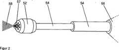
Im Inneren der Düse
Die sieben Flüssigkeitsleitungen im Inneren der Düse
Dadurch treffen sieben Spülflüssigkeitsstrahlen (in
Der teleskopartige Aufbau des Austragsrohrs
Die in der voranstehenden Beschreibung, sowie den Ansprüchen, Figuren und Ausführungsbeispielen offenbarten Merkmale der Erfindung können sowohl einzeln, als auch in jeder beliebigen Kombination für die Verwirklichung der Erfindung in ihren verschiedenen Ausführungsformen wesentlich sein.The features of the invention disclosed in the foregoing description, as well as the claims, figures and embodiments may be essential both individually and in any combination for the realization of the invention in its various embodiments.
BezugszeichenlisteLIST OF REFERENCE NUMBERS
- 11
- Innengewindeinner thread
- 22
- Außengewindeexternal thread
- 44
- Druckgasreservoir/DruckgaspatronePressure gas reservoir / compressed gas cartridge
- 66
- DrehgriffstückRotary handle
- 88th
- Hohldornhollow mandrel
- 99
- DruckgasleitungPressure gas line
- 1010
- VerdampfungsraumEvaporation space
- 1212
- DruckminderungsventilPressure reducing valve
- 1414
- ÜberdruckventilPressure relief valve
- 1515
- ÜberdruckventilPressure relief valve
- 1616
- Flaschebottle
- 1818
- Medizinische SpülflüssigkeitMedical rinse
- 2020
- Überstehende GasphaseSupernatant gas phase
- 2222
- Flüssigkeitsleitungliquid line
- 2424
- Düsejet
- 2626
- Gehäusecasing
- 2828
- Pistolengriffpistol butt
- 3030
- Ventilelementvalve element
- 3232
- Abzugdeduction
- 3434
- Austragsrohrdischarge pipe
- 3636
- Kanalchannel
- 3838
- Zerstäubungsraumnebulization
- 5252
- Düsejet
- 54 54
- Austragsrohrdischarge pipe
- 5656
- Gehäusecasing
- 5757
- Zerstäubungsraumnebulization
- 5858
- Sprühkegelspray cones
ZITATE ENTHALTEN IN DER BESCHREIBUNG QUOTES INCLUDE IN THE DESCRIPTION
Diese Liste der vom Anmelder aufgeführten Dokumente wurde automatisiert erzeugt und ist ausschließlich zur besseren Information des Lesers aufgenommen. Die Liste ist nicht Bestandteil der deutschen Patent- bzw. Gebrauchsmusteranmeldung. Das DPMA übernimmt keinerlei Haftung für etwaige Fehler oder Auslassungen.This list of the documents listed by the applicant has been generated automatically and is included solely for the better information of the reader. The list is not part of the German patent or utility model application. The DPMA assumes no liability for any errors or omissions.
Zitierte PatentliteraturCited patent literature
- US 4583531 A[0004]US 4583531 A[0004]
- US 4278078 A[0004]US 4278078 A[0004]
- US 5542918 A[0004]US 5542918 A[0004]
Zitierte Nicht-PatentliteraturCited non-patent literature
- R. M. Sherman et al.: The role of lavage in preventing hemodynamic and blood-gas changes during cemented arthroplasty. J. Bone Joint. Surg. 1983; 65-A: 500–506[0004]RM Sherman et al .: The role of lavage in hemodynamic and blood-gas changes during cemented arthroplasty. J. Bone Joint. Surg. 1983; 65-A: 500-506[0004]
- S. J. Breusch et al.: Lavage technique in THA: Jet-lavage Produces Better Cement Penetration Than Syringe-Lavage in the Proximal Femur. J. Arthroplasty. 200; 15(7): 921–927[0004]SJ Breusch et al .: Lava technique in THA: Jet lavage Produces Better Cement Penetration Than Syringe Lavage in the Proximal Femur. J. Arthroplasty. 200; 15 (7): 921-927[0004]
- R. J. Byrick et al.: High-volume, high pressure pulsatile lavage during cemented arthroplasty. J. Bone Joint Surg. 1989; 81-A: 1331–1336[0004]RJ Byrick et al .: High-volume, high-pressure pulsatile lavage during cemented arthroplasty. J. Bone Joint Surg. 1989; 81-A: 1331-1336[0004]
- J. Christie et al.: Medullary lavage reduces embolic phenomena and cardiopulmonary changes during cemented hemiarthorplasty. J. Bone Joint Surg. 1995; 77-B: 456–459[0004]J. Christie et al .: Medullary lavage reduces embolic and cardiopulmonary changes during cemented hemiarthorplasty. J. Bone Joint Surg. 1995; 77-B: 456-459[0004]
Claims (22)
Translated fromGermanPriority Applications (7)
| Application Number | Priority Date | Filing Date | Title |
|---|---|---|---|
| DE102013210539.8ADE102013210539A1 (en) | 2013-06-06 | 2013-06-06 | Medical spray device with nozzle and method for generating a spray cone |
| CA2852356ACA2852356C (en) | 2013-06-06 | 2014-05-20 | Medical spraying device with nozzle, and method for producing a spray cone |
| JP2014104249AJP6162642B2 (en) | 2013-06-06 | 2014-05-20 | Medical spray device with nozzle and method for producing spray cone |
| EP14169452.1AEP2810670B1 (en) | 2013-06-06 | 2014-05-22 | Medical spraying device with nozzle, and method for producing a spray cone |
| AU2014202803AAU2014202803B2 (en) | 2013-06-06 | 2014-05-22 | Medical spraying device with nozzle, and method for producing a spray cone |
| US14/297,665US9744316B2 (en) | 2013-06-06 | 2014-06-06 | Medical spraying device with nozzle, and method for producing a spray cone |
| CN201410251023.XACN104225704B (en) | 2013-06-06 | 2014-06-06 | Medical injection apparatus with nozzle and the method for producing spray-cone |
Applications Claiming Priority (1)
| Application Number | Priority Date | Filing Date | Title |
|---|---|---|---|
| DE102013210539.8ADE102013210539A1 (en) | 2013-06-06 | 2013-06-06 | Medical spray device with nozzle and method for generating a spray cone |
Publications (1)
| Publication Number | Publication Date |
|---|---|
| DE102013210539A1true DE102013210539A1 (en) | 2014-12-11 |
Family
ID=50842053
Family Applications (1)
| Application Number | Title | Priority Date | Filing Date |
|---|---|---|---|
| DE102013210539.8AWithdrawnDE102013210539A1 (en) | 2013-06-06 | 2013-06-06 | Medical spray device with nozzle and method for generating a spray cone |
Country Status (7)
| Country | Link |
|---|---|
| US (1) | US9744316B2 (en) |
| EP (1) | EP2810670B1 (en) |
| JP (1) | JP6162642B2 (en) |
| CN (1) | CN104225704B (en) |
| AU (1) | AU2014202803B2 (en) |
| CA (1) | CA2852356C (en) |
| DE (1) | DE102013210539A1 (en) |
Families Citing this family (13)
| Publication number | Priority date | Publication date | Assignee | Title |
|---|---|---|---|---|
| DE102012013464A1 (en)* | 2012-05-07 | 2013-11-07 | Heraeus Medical Gmbh | Lavage system with nozzle |
| DE102013210511A1 (en)* | 2013-06-06 | 2014-12-11 | Heraeus Medical Gmbh | Medical sprayer with overpressure valve and method for generating a spray cone |
| CN107913175A (en)* | 2017-11-15 | 2018-04-17 | 盐城市斯壮格安全设备有限公司 | Lab bench eye syringe |
| BR112020018869A2 (en) | 2018-03-21 | 2020-12-29 | Softhale Nv | ASPERSION NOZZLE FOR AN INHALATION DEVICE |
| FR3086514B1 (en)* | 2018-10-02 | 2021-10-15 | Oreal | HAIR COLORING PROCESS |
| CN112888386B (en)* | 2018-10-22 | 2024-07-30 | 奥林巴斯株式会社 | Treatment device |
| EP3760242A1 (en)* | 2019-07-02 | 2021-01-06 | Biotronik Ag | Functionalized balloon surface |
| CN111888537A (en)* | 2020-07-30 | 2020-11-06 | 李亚璇 | Inflammation wound disinfection nursing device |
| JP7695338B2 (en)* | 2020-08-21 | 2025-06-18 | バクスター・インターナショナル・インコーポレイテッド | Handheld gas atomizing system for mixing and dispensing multi-component compositions |
| CN112843404A (en)* | 2020-12-30 | 2021-05-28 | 武汉维斯第医用科技股份有限公司 | Intermittent quantitative high-viscosity biological preparation spraying gun |
| CN112915304B (en)* | 2021-03-09 | 2023-03-17 | 孔丽丽 | All-round liquid medicine feeder of gynaecology |
| CN117138232B (en)* | 2023-08-22 | 2024-03-26 | 广州力加贺电子科技有限公司 | Beauty machine head and beauty instrument |
| CN116870347B (en)* | 2023-09-06 | 2023-11-17 | 山东维璟医疗器械股份有限公司 | Spraying device for liquid medicament-based treatment |
Citations (6)
| Publication number | Priority date | Publication date | Assignee | Title |
|---|---|---|---|---|
| US4278078A (en) | 1980-02-26 | 1981-07-14 | Stryker Corporation | Lavage handpiece |
| US4583531A (en) | 1984-03-02 | 1986-04-22 | Terry M. Mattchen | Hand-held pulsating jet lavage |
| US5542918A (en) | 1995-01-06 | 1996-08-06 | Zimmer, Inc. | Vacuum driven fluid pump for an aspiration/irrigation instrument |
| DE10300983A1 (en)* | 2003-01-14 | 2004-07-22 | Boehringer Ingelheim Pharma Gmbh & Co. Kg | Jet system for an inhaler, to deliver a mist of fluid droplets, has inner surfaces with micro- or nano-structures on the surfaces in contact with the aerosol flow to reduce precipitation |
| DE69832640T2 (en)* | 1997-03-26 | 2006-06-08 | Innovation Technologies, Inc., Gainsville | DEVICE FOR WOUNDIRRIGATION |
| US20110041844A1 (en)* | 2008-01-16 | 2011-02-24 | Boehringer Ingelheim Pharma Gmbh & Co. Kg | Nozzle and inhaler and method for producing a nozzle |
Family Cites Families (25)
| Publication number | Priority date | Publication date | Assignee | Title |
|---|---|---|---|---|
| US2323464A (en) | 1942-05-21 | 1943-07-06 | Akron Brass Mfg Company Inc | Spray nozzle |
| US2717804A (en)* | 1946-05-06 | 1955-09-13 | Jr Roby Byron White | Spray gun |
| US2631891A (en)* | 1948-04-20 | 1953-03-17 | Knapp Monarch Co | Pressure sprayer |
| FR1087714A (en)* | 1953-11-23 | 1955-02-28 | Spray method and device | |
| US4157093A (en)* | 1978-02-09 | 1979-06-05 | Brodsky Ralph H | Hygiene system |
| US4681262A (en)* | 1985-09-27 | 1987-07-21 | The Sherwin-Williams Company | Cap connecting propellant container with material container |
| US20010037095A1 (en)* | 1994-06-14 | 2001-11-01 | Rucinski Paul J. | Novel wound irrigation device and method |
| GB9818110D0 (en)* | 1998-08-19 | 1998-10-14 | Weston Medical Ltd | Needleless injectors and other devices |
| DE10004534C2 (en) | 2000-02-02 | 2003-09-04 | Baasch Elke | Method and device for controlling a massage jet that can be emitted from a hydromassage nozzle |
| GB0012165D0 (en)* | 2000-05-20 | 2000-07-12 | Team Consulting Ltd | Portable device with consistent power output |
| FR2818101B1 (en)* | 2000-12-15 | 2003-09-26 | Oreal | DEVICE FOR SPRAYING A COSMETIC PRODUCT |
| JP3081531U (en)* | 2001-04-12 | 2001-11-09 | 柾路 安孫子 | Pneumatic portable cleaning tool |
| WO2003049811A1 (en)* | 2001-12-13 | 2003-06-19 | Rd, Inc. | Spraying system for dispersing and disseminating fluids |
| DE10226792B4 (en)* | 2002-06-15 | 2004-10-28 | J. Wagner Gmbh | spray gun |
| JP3640209B2 (en)* | 2002-06-28 | 2005-04-20 | 識雄 浦 | Spray nozzle |
| US7621266B2 (en) | 2003-01-14 | 2009-11-24 | Boehringer Ingelheim International Gmbh | Nozzle-system for a dispenser for fluids consisting of a nozzle and a nozzle-holder and/or screw cap |
| ATE474613T1 (en)* | 2003-02-03 | 2010-08-15 | Bioware Technology Co Ltd | GENE GUN WITH LOW PRESSURE GAS ACCELERATION |
| GB0422106D0 (en)* | 2004-10-06 | 2004-11-03 | Dunne Stephen T | Powder dispensing means |
| RU2375121C2 (en)* | 2005-05-20 | 2009-12-10 | Грундфос Нонокс А/С | Dispersal of fluid mediums by means of mutual impact of fluid mediums flows |
| JP4691436B2 (en)* | 2005-11-18 | 2011-06-01 | 出光エンジニアリング株式会社 | Fuel spray tip, fuel combustion apparatus, and fuel combustion method |
| US20130014961A1 (en)* | 2010-03-04 | 2013-01-17 | Vid Fire-Kill Aps | Modular automatic spray nozzle |
| WO2011127669A1 (en) | 2010-04-14 | 2011-10-20 | Lee Jui-Jen | Atomization cleaning health device and method for atomizing |
| US9227006B2 (en)* | 2010-05-28 | 2016-01-05 | Sterilab, Inc. | Non-penetrating nozzle |
| DE102011018708A1 (en)* | 2011-04-26 | 2012-10-31 | Heraeus Medical Gmbh | Spray device for use in compressed air driven lavage system for cleaning tissue area during e.g. implantation of joint endoprosthesis in operating room, has piston vibrator serving as drive unit and operated by using compressed gas |
| CN103006323B (en)* | 2012-11-21 | 2014-12-10 | 首都医科大学 | Liquid spray part, cleaning gun and wound surface processing device |
- 2013
- 2013-06-06DEDE102013210539.8Apatent/DE102013210539A1/ennot_activeWithdrawn
- 2014
- 2014-05-20CACA2852356Apatent/CA2852356C/ennot_activeExpired - Fee Related
- 2014-05-20JPJP2014104249Apatent/JP6162642B2/ennot_activeExpired - Fee Related
- 2014-05-22AUAU2014202803Apatent/AU2014202803B2/ennot_activeCeased
- 2014-05-22EPEP14169452.1Apatent/EP2810670B1/ennot_activeNot-in-force
- 2014-06-06USUS14/297,665patent/US9744316B2/ennot_activeExpired - Fee Related
- 2014-06-06CNCN201410251023.XApatent/CN104225704B/ennot_activeExpired - Fee Related
Patent Citations (6)
| Publication number | Priority date | Publication date | Assignee | Title |
|---|---|---|---|---|
| US4278078A (en) | 1980-02-26 | 1981-07-14 | Stryker Corporation | Lavage handpiece |
| US4583531A (en) | 1984-03-02 | 1986-04-22 | Terry M. Mattchen | Hand-held pulsating jet lavage |
| US5542918A (en) | 1995-01-06 | 1996-08-06 | Zimmer, Inc. | Vacuum driven fluid pump for an aspiration/irrigation instrument |
| DE69832640T2 (en)* | 1997-03-26 | 2006-06-08 | Innovation Technologies, Inc., Gainsville | DEVICE FOR WOUNDIRRIGATION |
| DE10300983A1 (en)* | 2003-01-14 | 2004-07-22 | Boehringer Ingelheim Pharma Gmbh & Co. Kg | Jet system for an inhaler, to deliver a mist of fluid droplets, has inner surfaces with micro- or nano-structures on the surfaces in contact with the aerosol flow to reduce precipitation |
| US20110041844A1 (en)* | 2008-01-16 | 2011-02-24 | Boehringer Ingelheim Pharma Gmbh & Co. Kg | Nozzle and inhaler and method for producing a nozzle |
Non-Patent Citations (4)
| Title |
|---|
| J. Christie et al.: Medullary lavage reduces embolic phenomena and cardiopulmonary changes during cemented hemiarthorplasty. J. Bone Joint Surg. 1995; 77-B: 456-459 |
| R. J. Byrick et al.: High-volume, high pressure pulsatile lavage during cemented arthroplasty. J. Bone Joint Surg. 1989; 81-A: 1331-1336 |
| R. M. Sherman et al.: The role of lavage in preventing hemodynamic and blood-gas changes during cemented arthroplasty. J. Bone Joint. Surg. 1983; 65-A: 500-506 |
| S. J. Breusch et al.: Lavage technique in THA: Jet-lavage Produces Better Cement Penetration Than Syringe-Lavage in the Proximal Femur. J. Arthroplasty. 200; 15(7): 921-927 |
Also Published As
| Publication number | Publication date |
|---|---|
| CN104225704B (en) | 2018-02-13 |
| CA2852356A1 (en) | 2014-12-06 |
| EP2810670A1 (en) | 2014-12-10 |
| JP2014236974A (en) | 2014-12-18 |
| JP6162642B2 (en) | 2017-07-12 |
| CN104225704A (en) | 2014-12-24 |
| AU2014202803B2 (en) | 2015-02-26 |
| AU2014202803A1 (en) | 2015-01-15 |
| CA2852356C (en) | 2018-09-18 |
| US20140364816A1 (en) | 2014-12-11 |
| US9744316B2 (en) | 2017-08-29 |
| EP2810670B1 (en) | 2018-03-07 |
Similar Documents
| Publication | Publication Date | Title |
|---|---|---|
| EP2810670B1 (en) | Medical spraying device with nozzle, and method for producing a spray cone | |
| EP2810671B1 (en) | Medical spraying device with pressure relief valve, and method for producing a spray cone | |
| EP2810672B1 (en) | Medical spraying device with pressure reduction valve, and method of producing a spray cone | |
| EP2662146B1 (en) | Lavage system with nozzle | |
| EP2619415B1 (en) | Compressed gas motor for a wash system | |
| WO2012048434A1 (en) | Medical spray-head with compressed gas assistance | |
| DE102011018708A1 (en) | Spray device for use in compressed air driven lavage system for cleaning tissue area during e.g. implantation of joint endoprosthesis in operating room, has piston vibrator serving as drive unit and operated by using compressed gas | |
| DE102013214032A1 (en) | Spray applicator and dispensing device for spraying a multi-component fluid | |
| WO2022242831A1 (en) | Application device | |
| WO2005113041A1 (en) | Cleaning and/or drying device for human and veterinary medical applications | |
| DE4119132A1 (en) | Catheter medium-discharge head - has nozzle discharge direction adjustable in relation to main body | |
| DE1281630B (en) | Device for root canal treatment of teeth |
Legal Events
| Date | Code | Title | Description |
|---|---|---|---|
| R012 | Request for examination validly filed | ||
| R016 | Response to examination communication | ||
| R082 | Change of representative | Representative=s name:SCHULTHEISS & STERZEL PATENTANWAELTE PARTG MBB, DE | |
| R016 | Response to examination communication | ||
| R119 | Application deemed withdrawn, or ip right lapsed, due to non-payment of renewal fee |