DE102013209436A1 - Apparatus and method for generating a lighting pattern - Google Patents
Apparatus and method for generating a lighting patternDownload PDFInfo
- Publication number
- DE102013209436A1 DE102013209436A1DE201310209436DE102013209436ADE102013209436A1DE 102013209436 A1DE102013209436 A1DE 102013209436A1DE 201310209436DE201310209436DE 201310209436DE 102013209436 ADE102013209436 ADE 102013209436ADE 102013209436 A1DE102013209436 A1DE 102013209436A1
- Authority
- DE
- Germany
- Prior art keywords
- light beam
- designed
- diffractive optical
- optical elements
- contraption
- Prior art date
- Legal status (The legal status is an assumption and is not a legal conclusion. Google has not performed a legal analysis and makes no representation as to the accuracy of the status listed.)
- Withdrawn
Links
Images


Classifications
- G—PHYSICS
- G01—MEASURING; TESTING
- G01B—MEASURING LENGTH, THICKNESS OR SIMILAR LINEAR DIMENSIONS; MEASURING ANGLES; MEASURING AREAS; MEASURING IRREGULARITIES OF SURFACES OR CONTOURS
- G01B11/00—Measuring arrangements characterised by the use of optical techniques
- G01B11/24—Measuring arrangements characterised by the use of optical techniques for measuring contours or curvatures
- G01B11/25—Measuring arrangements characterised by the use of optical techniques for measuring contours or curvatures by projecting a pattern, e.g. one or more lines, moiré fringes on the object
- G01B11/2513—Measuring arrangements characterised by the use of optical techniques for measuring contours or curvatures by projecting a pattern, e.g. one or more lines, moiré fringes on the object with several lines being projected in more than one direction, e.g. grids, patterns
- G—PHYSICS
- G02—OPTICS
- G02B—OPTICAL ELEMENTS, SYSTEMS OR APPARATUS
- G02B5/00—Optical elements other than lenses
- G02B5/18—Diffraction gratings
- G02B5/1814—Diffraction gratings structurally combined with one or more further optical elements, e.g. lenses, mirrors, prisms or other diffraction gratings
- G02B5/1819—Plural gratings positioned on the same surface, e.g. array of gratings
- G—PHYSICS
- G02—OPTICS
- G02B—OPTICAL ELEMENTS, SYSTEMS OR APPARATUS
- G02B5/00—Optical elements other than lenses
- G02B5/18—Diffraction gratings
- G02B5/1828—Diffraction gratings having means for producing variable diffraction
Landscapes
- Physics & Mathematics (AREA)
- General Physics & Mathematics (AREA)
- Optics & Photonics (AREA)
- Engineering & Computer Science (AREA)
- Computer Vision & Pattern Recognition (AREA)
- Lighting Device Outwards From Vehicle And Optical Signal (AREA)
Abstract
Translated fromGermanDescription
Translated fromGermanDie Erfindung betrifft eine Vorrichtung und ein Verfahren zum Erzeugen eines Beleuchtungsmusters.The invention relates to an apparatus and a method for generating a lighting pattern.
Stand der TechnikState of the art
Die
Offenbarung der ErfindungDisclosure of the invention
Die vorliegende Erfindung schafft eine Vorrichtung zum Erzeugen eines Beleuchtungsmusters mit den Merkmalen des Patentanspruchs 1 und ein Verfahren zum Erzeugen eines Beleuchtungsmusters gemäß Patentanspruch 8.The present invention provides a device for generating a lighting pattern having the features of
Vorteile der ErfindungAdvantages of the invention
Der Kern der Erfindung liegt darin, dass unter Verwendung von mindestens zwei unveränderlichen diffraktiven optischen Elementen in dem optischen Aufbau der Vorrichtung beim Projizieren ein Wechsel zwischen verschiedenen Beleuchtungsmustern ermöglicht wird.The gist of the invention is that by using at least two invariable diffractive optical elements in the optical design of the device, when projecting a change between different illumination patterns is made possible.
Die Vorrichtung zum Erzeugen eines Beleuchtungsmusters umfasst eine steuerbare Ablenkeinrichtung und mindestens zwei diffraktive optische Elemente. Die Ablenkeinrichtung richtet das Licht der Beleuchtungsquelle auf eines der mindestens zwei diffraktiven optischen Elemente. Mit jedem der mindestens zwei diffraktiven optischen Elemente kann dabei ein individuelles Beleuchtungsmuster zur Szeneriebeleuchtung erzeugt werden.The device for generating an illumination pattern comprises a controllable deflection device and at least two diffractive optical elements. The deflection device directs the light of the illumination source to one of the at least two diffractive optical elements. With each of the at least two diffractive optical elements, an individual lighting pattern for scene lighting can be generated.
Der Einsatz aufwendiger und veränderbarer diffraktiver optischer Elemente, wie etwa Flächenlichtmodulatoren, entfällt. Ein weiterer Vorteil der vorliegenden Erfindung liegt darin, dass die Vorrichtung zum Erzeugen eines Beleuchtungsmusters im Vergleich zu Systemen mit Flächenlichtmodulatoren wesentlich kostengünstiger darstellbar ist.The use of complex and changeable diffractive optical elements, such as surface light modulators, is eliminated. A further advantage of the present invention is that the device for generating a lighting pattern can be displayed much more cost-effectively compared to systems with area light modulators.
Ferner erlaubt die Vorrichtung der vorliegenden Erfindung vorteilhaft, auf aufwendige Anordnungen mit separaten und somit mehrfach vorhandenen Lichtquellen und einer Vielzahl von optischen Lichtwegen verzichten zu können.Furthermore, the device of the present invention advantageously allows to dispense with complex arrangements with separate and thus multiple existing light sources and a plurality of optical light paths.
Vorteilhafte Ausführungsformen und Weiterbildungen ergeben sich aus den Unteransprüchen sowie aus der Beschreibung unter Bezugnahme auf die Figuren.Advantageous embodiments and further developments emerge from the dependent claims and from the description with reference to the figures.
Gemäß einer Ausführungsform der Erfindung ist vorgesehen, dass die Beleuchtungsquelle als eine Laserlichtquelle ausgelegt ist. Dies erlaubt vorteilhaft, eine platzsparende Bauweise der Vorrichtung zu erreichen.According to one embodiment of the invention, it is provided that the illumination source is designed as a laser light source. This advantageously allows to achieve a space-saving design of the device.
Gemäß einer Ausführungsform der Erfindung ist vorgesehen, dass die mindestens zwei diffraktiven optischen Elemente dazu ausgelegt sind, als das Beleuchtungsmuster ein Gitter-, Linien-, oder Punkteraster zu erzeugen. Dadurch kann vorteilhaft eine Verwendung eines für die vorherrschende Umgebungsbedingungen geeigneten Beleuchtungsmusters sichergestellt werden.According to one embodiment of the invention, it is provided that the at least two diffractive optical elements are designed to generate a grid, line, or point grid as the illumination pattern. This advantageously ensures the use of a suitable illumination pattern for the prevailing ambient conditions.
Gemäß einer Ausführungsform der Erfindung ist vorgesehen, dass die Ablenkeinrichtung als eine Flüssiglinse ausgebildet ist. Dies erlaubt eine schnelle Änderung des Lichtweges.According to one embodiment of the invention it is provided that the deflection device is designed as a liquid lens. This allows a quick change of the light path.
Gemäß einer Ausführungsform der Erfindung ist vorgesehen, dass die Ablenkeinrichtung als ein Mikrospiegel ausgebildet ist.According to one embodiment of the invention it is provided that the deflection device is designed as a micromirror.
Gemäß einer Ausführungsform der Erfindung ist vorgesehen, dass die Vorrichtung ferner eine Erfassungseinrichtung aufweist, welche dazu ausgelegt ist, eine Fahr- und/oder Umgebungssituation eines Kraftfahrzeuges zu erfassen und die Ablenkeinrichtung dazu ausgelegt ist, anhand der erfassten Fahr- und/oder Umgebungssituation ein geeignetes Beleuchtungsmuster durch ein entsprechendes Ablenken des Lichtstrahls auf eine der mindestens zwei diffraktiven optischen Elemente zu erzeugen. Solche Kamerasysteme, insbesondere Stereokamerasysteme, können vorzugsweise für unterschiedliche Fahrerassistenzsysteme in einem Kraftfahrzeug verwendet werden, wie etwa Nachtsicht, Verkehrszeichenerkennung, Parklückenvermessung, Rückfahrkamera. Hierzu ist vorgesehen, dass im Kraftfahrzeug Beleuchtungssysteme verwendet werden, bei denen mit Hilfe von Beleuchtungsmustern, die in eine Szenerie projiziert werden, wichtige Zusatzinformationen über vorhandene Objekte gewonnen werden können. According to one embodiment of the invention, it is provided that the device further comprises a detection device which is designed to detect a driving and / or surrounding situation of a motor vehicle and the deflection device is designed to be suitable based on the detected driving and / or surrounding situation To generate illumination pattern by a corresponding deflection of the light beam to one of the at least two diffractive optical elements. Such camera systems, in particular stereo camera systems, can preferably be used for different driver assistance systems in a motor vehicle, such as night vision, traffic sign recognition, parking space measurement, reversing camera. For this purpose, provision is made for illumination systems to be used in the motor vehicle in which important additional information about existing objects can be obtained with the aid of illumination patterns that are projected into a scene.
Gemäß einer Ausführungsform der Erfindung ist vorgesehen, dass die Vorrichtung ferner eine Erfassungseinrichtung aufweist, welche dazu ausgelegt ist, Objekte im Umfeld eines Kraftfahrzeuges zu erfassen und die Ablenkeinrichtung dazu ausgelegt ist, zum Erkennen von Kannten und/oder Strukturen der erfassten Objekte ein geeignetes Beleuchtungsmuster durch ein entsprechendes Ablenken des Lichtstrahls auf eine der mindestens zwei diffraktiven optischen Elemente zu erzeugen.According to one embodiment of the invention, it is provided that the device further comprises a detection device which is designed to detect objects in the environment of a motor vehicle and the deflection device is designed to detect a suitable illumination pattern for detecting identities and / or structures of the detected objects to generate a corresponding deflection of the light beam to one of the at least two diffractive optical elements.
Die beschriebenen Ausgestaltungen und Weiterbildungen lassen sich beliebig miteinander kombinieren.The described embodiments and developments can be combined with each other as desired.
Weitere mögliche Ausgestaltungen, Weiterbildungen und Implementierungen der Erfindung umfassen auch nicht explizit genannte Kombinationen von zuvor oder im Folgenden bezüglich der Ausführungsbeispiele beschriebenen Merkmale der Erfindung.Further possible refinements, developments and implementations of the invention also include combinations, not explicitly mentioned, of features of the invention described above or below with regard to the exemplary embodiments.
Kurze Beschreibung der ZeichnungenBrief description of the drawings
Die beiliegenden Zeichnungen sollen ein weiteres Verständnis der Ausführungsformen der Erfindung vermitteln. Sie veranschaulichen Ausführungsformen und dienen im Zusammenhang mit der Beschreibung der Erklärung von Prinzipien und Konzepten der Erfindung.The accompanying drawings are intended to provide further understanding of the embodiments of the invention. They illustrate embodiments and, together with the description, serve to explain principles and concepts of the invention.
Andere Ausführungsformen und viele der genannten Vorteile ergeben sich im Hinblick auf die Zeichnungen. Die dargestellten Elemente der Zeichnungen sind nicht notwendigerweise maßstabsgetreu zueinander gezeigt.Other embodiments and many of the stated advantages will become apparent with reference to the drawings. The illustrated elements of the drawings are not necessarily shown to scale to each other.
Es zeigen:Show it:
In den Figuren der Zeichnung bezeichnen gleiche Bezugszeichen gleiche oder funktionsgleiche Elemente, Bauteile, Komponenten oder Verfahrensschritte, soweit nichts Gegenteiliges angegeben ist.In the figures of the drawing, like reference numerals designate the same or functionally identical elements, components, components or method steps, unless indicated otherwise.
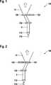
Die
Die Vorrichtung
In der
Das Licht einer als Beleuchtungsquelle
Ein Vorteil ist bei der dargestellten Vorrichtung
Es ergeben sich Tiefenschärfebereiche der Vorrichtung
Die Vorrichtung
Denkbar ist auch ein einzelnes Phasengitter, das beim Herstellungsprozess mit mehreren, räumlich klar voneinander getrennten Strukturen versehen wurde. Die verschiedenen Phasengitter oder die verschiedenen Bereiche eines einzelnen Phasengitters bewirken dabei eine unterschiedlich geartete Umverteilung und Projektion des Lichtstrahls
Als Ablenkeinrichtung
Flüssiglinsen können durch Anlegen einer Spannung so beeinflusst werden, dass ein Strahl nach Durchgang durch die Linse relativ zu seiner Einfallsachse verkippt wird. Die Verkippung des Lichtstrahls
Die Erfindung kann als Beleuchtungseinheit für ein 3D-Bildgebungsystem auf der Basis einer strukturierten Beleuchtung verwendet werden. Hier können die diffraktiven optischen Elemente beispielsweise als Strahlteiler wirken, die in der Projektionseben Punktemuster erzeugen, wie in den
Je nach Umgebungslichtbedingungen kann es dann sinnvoll sein, dass Licht in eine unterschiedliche Zahl von Punkten zu lenken, d. h. Punktemuster mit hoher oder geringer Punktedichte zu erzeugen.Depending on the ambient light conditions, it may then make sense to direct the light into a different number of points, d. H. Create dot patterns with high or low dot density.
Große Unterschiede in den Umgebungslichtbedingungen sind etwa typisch für den Fahrzeugbereich. Denkbar ist nun beispielsweise der Fall, dass bei hohem Umgebungslichtanteil nur wenige Punkte in der Projektionsebene erzeugt werden, die dann aber ein höheres Nutzsignal liefern.Large differences in the ambient light conditions are typical for the vehicle sector. It is conceivable, for example, the case that at high ambient light component only a few points are generated in the projection plane, but then provide a higher useful signal.
Bei Dunkelheit hingegen könnte ein diffraktives optisches Element angesteuert werden, dass eine Vielzahl von Einzelstrahlen erzeugt. In diesem Falle werden Strukturen in der Szenerie besser auflösen.In the dark, on the other hand, a diffractive optical element could be triggered that generates a large number of individual beams. In this case structures in the scenery will dissolve better.
Die
Abweichend von der in der
Die weiteren in der
Die
Das Beleuchtungsmuster
Die
Das Beleuchtungsmuster
Die
Abweichend von der in den
Die als Flüssigklinse ausgebildet Ablenkeinrichtung
Alternativ kann als Ablenkeinheit auch ein quasi-statisch bewegter Spiegel verwendet werden. Hier besteht der Vorteil, dass im Allgemeinen deutlich größere Ablenkwinkel von bis zu 20° erreicht werden.Alternatively, as a deflection unit, a quasi-static moving mirror can also be used. Here there is the advantage that in general significantly larger deflection angle of up to 20 ° can be achieved.
Ferner umfasst die Vorrichtung
Bei der in der
Die weiteren in der
Die
Als ein erster Verfahrensschritt erfolgt ein Erzeugen S1 eines Lichtstrahls
Als ein zweiter Verfahrensschritt erfolgt ein Ablenken S2 des Lichtstrahls
Als ein dritter Verfahrensschritt erfolgt ein Beugen S3 des Lichtstrahls
Die Verfahrensschritte des Verfahrens können dabei iterativ oder rekursiv in beliebiger Reihenfolge wiederholt werden.The method steps of the method can be repeated iteratively or recursively in any order.
Obwohl die vorliegende Erfindung anhand bevorzugter Ausführungsbeispiele vorstehend beschrieben wurde, ist sie darauf nicht beschränkt, sondern auf vielfältige Art und Weise modifizierbar. Insbesondere lässt sich die Erfindung in mannigfaltiger Weise verändern oder modifizieren, ohne vom Kern der Erfindung abzuweichen.Although the present invention has been described above with reference to preferred embodiments, it is not limited thereto, but modifiable in a variety of ways. In particular, the invention can be varied or modified in many ways without deviating from the gist of the invention.
ZITATE ENTHALTEN IN DER BESCHREIBUNG QUOTES INCLUDE IN THE DESCRIPTION
Diese Liste der vom Anmelder aufgeführten Dokumente wurde automatisiert erzeugt und ist ausschließlich zur besseren Information des Lesers aufgenommen. Die Liste ist nicht Bestandteil der deutschen Patent- bzw. Gebrauchsmusteranmeldung. Das DPMA übernimmt keinerlei Haftung für etwaige Fehler oder Auslassungen.This list of the documents listed by the applicant has been generated automatically and is included solely for the better information of the reader. The list is not part of the German patent or utility model application. The DPMA assumes no liability for any errors or omissions.
Zitierte PatentliteraturCited patent literature
- DE 102011017707 A1[0002]DE 102011017707 A1[0002]
Claims (8)
Translated fromGermanPriority Applications (1)
| Application Number | Priority Date | Filing Date | Title |
|---|---|---|---|
| DE201310209436DE102013209436A1 (en) | 2013-05-22 | 2013-05-22 | Apparatus and method for generating a lighting pattern |
Applications Claiming Priority (1)
| Application Number | Priority Date | Filing Date | Title |
|---|---|---|---|
| DE201310209436DE102013209436A1 (en) | 2013-05-22 | 2013-05-22 | Apparatus and method for generating a lighting pattern |
Publications (1)
| Publication Number | Publication Date |
|---|---|
| DE102013209436A1true DE102013209436A1 (en) | 2014-11-27 |
Family
ID=51863112
Family Applications (1)
| Application Number | Title | Priority Date | Filing Date |
|---|---|---|---|
| DE201310209436WithdrawnDE102013209436A1 (en) | 2013-05-22 | 2013-05-22 | Apparatus and method for generating a lighting pattern |
Country Status (1)
| Country | Link |
|---|---|
| DE (1) | DE102013209436A1 (en) |
Cited By (36)
| Publication number | Priority date | Publication date | Assignee | Title |
|---|---|---|---|---|
| WO2017178781A1 (en)* | 2016-04-11 | 2017-10-19 | GRANT, Alastair, John | Holographic waveguide apparatus for structured light projection |
| DE102017215850A1 (en)* | 2017-09-08 | 2019-03-14 | Robert Bosch Gmbh | Diffractive optical element and method for its production |
| US10359736B2 (en) | 2014-08-08 | 2019-07-23 | Digilens Inc. | Method for holographic mastering and replication |
| US10527797B2 (en) | 2015-02-12 | 2020-01-07 | Digilens Inc. | Waveguide grating device |
| US10545346B2 (en) | 2017-01-05 | 2020-01-28 | Digilens Inc. | Wearable heads up displays |
| US10642058B2 (en) | 2011-08-24 | 2020-05-05 | Digilens Inc. | Wearable data display |
| US10678053B2 (en) | 2009-04-27 | 2020-06-09 | Digilens Inc. | Diffractive projection apparatus |
| US10690916B2 (en) | 2015-10-05 | 2020-06-23 | Digilens Inc. | Apparatus for providing waveguide displays with two-dimensional pupil expansion |
| US10732569B2 (en) | 2018-01-08 | 2020-08-04 | Digilens Inc. | Systems and methods for high-throughput recording of holographic gratings in waveguide cells |
| US10747982B2 (en) | 2013-07-31 | 2020-08-18 | Digilens Inc. | Method and apparatus for contact image sensing |
| US10859768B2 (en) | 2016-03-24 | 2020-12-08 | Digilens Inc. | Method and apparatus for providing a polarization selective holographic waveguide device |
| US10914950B2 (en) | 2018-01-08 | 2021-02-09 | Digilens Inc. | Waveguide architectures and related methods of manufacturing |
| US11106048B2 (en) | 2014-08-08 | 2021-08-31 | Digilens Inc. | Waveguide laser illuminator incorporating a despeckler |
| JP2021173844A (en)* | 2020-04-23 | 2021-11-01 | 大日本印刷株式会社 | Lighting device and illumination method |
| US11256155B2 (en) | 2012-01-06 | 2022-02-22 | Digilens Inc. | Contact image sensor using switchable Bragg gratings |
| US11378732B2 (en) | 2019-03-12 | 2022-07-05 | DigLens Inc. | Holographic waveguide backlight and related methods of manufacturing |
| US11402801B2 (en) | 2018-07-25 | 2022-08-02 | Digilens Inc. | Systems and methods for fabricating a multilayer optical structure |
| US11442222B2 (en) | 2019-08-29 | 2022-09-13 | Digilens Inc. | Evacuated gratings and methods of manufacturing |
| US11448937B2 (en) | 2012-11-16 | 2022-09-20 | Digilens Inc. | Transparent waveguide display for tiling a display having plural optical powers using overlapping and offset FOV tiles |
| US11487131B2 (en) | 2011-04-07 | 2022-11-01 | Digilens Inc. | Laser despeckler based on angular diversity |
| US11513350B2 (en) | 2016-12-02 | 2022-11-29 | Digilens Inc. | Waveguide device with uniform output illumination |
| DE102021210671A1 (en) | 2021-09-24 | 2022-12-01 | Carl Zeiss Smt Gmbh | INTENSITY ADJUSTING FILTER FOR AN OPTICAL ASSEMBLY AND OPTICAL ASSEMBLY WITH A RESPECTIVE INTENSITY ADJUSTING FILTER AND METHOD OF MANUFACTURE THEREOF |
| US11543594B2 (en) | 2019-02-15 | 2023-01-03 | Digilens Inc. | Methods and apparatuses for providing a holographic waveguide display using integrated gratings |
| US11561409B2 (en) | 2007-07-26 | 2023-01-24 | Digilens Inc. | Laser illumination device |
| US11681143B2 (en) | 2019-07-29 | 2023-06-20 | Digilens Inc. | Methods and apparatus for multiplying the image resolution and field-of-view of a pixelated display |
| US11726332B2 (en) | 2009-04-27 | 2023-08-15 | Digilens Inc. | Diffractive projection apparatus |
| US11726323B2 (en) | 2014-09-19 | 2023-08-15 | Digilens Inc. | Method and apparatus for generating input images for holographic waveguide displays |
| US11726329B2 (en) | 2015-01-12 | 2023-08-15 | Digilens Inc. | Environmentally isolated waveguide display |
| US11747568B2 (en) | 2019-06-07 | 2023-09-05 | Digilens Inc. | Waveguides incorporating transmissive and reflective gratings and related methods of manufacturing |
| US12092914B2 (en) | 2018-01-08 | 2024-09-17 | Digilens Inc. | Systems and methods for manufacturing waveguide cells |
| US12140764B2 (en) | 2019-02-15 | 2024-11-12 | Digilens Inc. | Wide angle waveguide display |
| US12158612B2 (en) | 2021-03-05 | 2024-12-03 | Digilens Inc. | Evacuated periodic structures and methods of manufacturing |
| US12210153B2 (en) | 2019-01-14 | 2025-01-28 | Digilens Inc. | Holographic waveguide display with light control layer |
| US12306585B2 (en) | 2018-01-08 | 2025-05-20 | Digilens Inc. | Methods for fabricating optical waveguides |
| US12399326B2 (en) | 2021-01-07 | 2025-08-26 | Digilens Inc. | Grating structures for color waveguides |
| US12397477B2 (en) | 2019-02-05 | 2025-08-26 | Digilens Inc. | Methods for compensating for optical surface nonuniformity |
Citations (1)
| Publication number | Priority date | Publication date | Assignee | Title |
|---|---|---|---|---|
| DE102011017707A1 (en) | 2011-04-28 | 2012-10-31 | Robert Bosch Gmbh | Method for detecting object e.g. concrete post in vicinity of camera for monitoring rear side region of vehicle, involves reading images captured by cameras after partially illuminating with illumination patterns |
- 2013
- 2013-05-22DEDE201310209436patent/DE102013209436A1/ennot_activeWithdrawn
Patent Citations (1)
| Publication number | Priority date | Publication date | Assignee | Title |
|---|---|---|---|---|
| DE102011017707A1 (en) | 2011-04-28 | 2012-10-31 | Robert Bosch Gmbh | Method for detecting object e.g. concrete post in vicinity of camera for monitoring rear side region of vehicle, involves reading images captured by cameras after partially illuminating with illumination patterns |
Cited By (66)
| Publication number | Priority date | Publication date | Assignee | Title |
|---|---|---|---|---|
| US11561409B2 (en) | 2007-07-26 | 2023-01-24 | Digilens Inc. | Laser illumination device |
| US11175512B2 (en) | 2009-04-27 | 2021-11-16 | Digilens Inc. | Diffractive projection apparatus |
| US11726332B2 (en) | 2009-04-27 | 2023-08-15 | Digilens Inc. | Diffractive projection apparatus |
| US10678053B2 (en) | 2009-04-27 | 2020-06-09 | Digilens Inc. | Diffractive projection apparatus |
| US11487131B2 (en) | 2011-04-07 | 2022-11-01 | Digilens Inc. | Laser despeckler based on angular diversity |
| US11287666B2 (en) | 2011-08-24 | 2022-03-29 | Digilens, Inc. | Wearable data display |
| US12306418B2 (en) | 2011-08-24 | 2025-05-20 | Rockwell Collins, Inc. | Wearable data display |
| US10642058B2 (en) | 2011-08-24 | 2020-05-05 | Digilens Inc. | Wearable data display |
| US11874477B2 (en) | 2011-08-24 | 2024-01-16 | Digilens Inc. | Wearable data display |
| US11256155B2 (en) | 2012-01-06 | 2022-02-22 | Digilens Inc. | Contact image sensor using switchable Bragg gratings |
| US11448937B2 (en) | 2012-11-16 | 2022-09-20 | Digilens Inc. | Transparent waveguide display for tiling a display having plural optical powers using overlapping and offset FOV tiles |
| US12405507B2 (en) | 2012-11-16 | 2025-09-02 | Digilens Inc. | Transparent waveguide display with grating lamina that both couple and extract modulated light |
| US10747982B2 (en) | 2013-07-31 | 2020-08-18 | Digilens Inc. | Method and apparatus for contact image sensing |
| US11307432B2 (en) | 2014-08-08 | 2022-04-19 | Digilens Inc. | Waveguide laser illuminator incorporating a Despeckler |
| US11106048B2 (en) | 2014-08-08 | 2021-08-31 | Digilens Inc. | Waveguide laser illuminator incorporating a despeckler |
| US10359736B2 (en) | 2014-08-08 | 2019-07-23 | Digilens Inc. | Method for holographic mastering and replication |
| US11709373B2 (en) | 2014-08-08 | 2023-07-25 | Digilens Inc. | Waveguide laser illuminator incorporating a despeckler |
| US11726323B2 (en) | 2014-09-19 | 2023-08-15 | Digilens Inc. | Method and apparatus for generating input images for holographic waveguide displays |
| US11726329B2 (en) | 2015-01-12 | 2023-08-15 | Digilens Inc. | Environmentally isolated waveguide display |
| US11740472B2 (en) | 2015-01-12 | 2023-08-29 | Digilens Inc. | Environmentally isolated waveguide display |
| US10527797B2 (en) | 2015-02-12 | 2020-01-07 | Digilens Inc. | Waveguide grating device |
| US11194098B2 (en) | 2015-02-12 | 2021-12-07 | Digilens Inc. | Waveguide grating device |
| US12379547B2 (en) | 2015-02-12 | 2025-08-05 | Digilens Inc. | Waveguide grating device |
| US11703645B2 (en) | 2015-02-12 | 2023-07-18 | Digilens Inc. | Waveguide grating device |
| US10690916B2 (en) | 2015-10-05 | 2020-06-23 | Digilens Inc. | Apparatus for providing waveguide displays with two-dimensional pupil expansion |
| US12405471B2 (en) | 2015-10-05 | 2025-09-02 | Digilens Inc. | Apparatus for providing waveguide displays with two-dimensional pupil expansion |
| US11754842B2 (en) | 2015-10-05 | 2023-09-12 | Digilens Inc. | Apparatus for providing waveguide displays with two-dimensional pupil expansion |
| US11281013B2 (en) | 2015-10-05 | 2022-03-22 | Digilens Inc. | Apparatus for providing waveguide displays with two-dimensional pupil expansion |
| US11604314B2 (en) | 2016-03-24 | 2023-03-14 | Digilens Inc. | Method and apparatus for providing a polarization selective holographic waveguide device |
| US10859768B2 (en) | 2016-03-24 | 2020-12-08 | Digilens Inc. | Method and apparatus for providing a polarization selective holographic waveguide device |
| US10890707B2 (en) | 2016-04-11 | 2021-01-12 | Digilens Inc. | Holographic waveguide apparatus for structured light projection |
| WO2017178781A1 (en)* | 2016-04-11 | 2017-10-19 | GRANT, Alastair, John | Holographic waveguide apparatus for structured light projection |
| JP2019520595A (en)* | 2016-04-11 | 2019-07-18 | ディジレンズ・インコーポレイテッド | Holographic waveguide device for structured light projection |
| CN109154717A (en)* | 2016-04-11 | 2019-01-04 | 迪吉伦斯公司 | Holographic waveguide device for project structured light |
| US11513350B2 (en) | 2016-12-02 | 2022-11-29 | Digilens Inc. | Waveguide device with uniform output illumination |
| US12298513B2 (en) | 2016-12-02 | 2025-05-13 | Digilens Inc. | Waveguide device with uniform output illumination |
| US12248150B2 (en) | 2017-01-05 | 2025-03-11 | Digilens Inc. | Wearable heads up displays |
| US11586046B2 (en) | 2017-01-05 | 2023-02-21 | Digilens Inc. | Wearable heads up displays |
| US11194162B2 (en) | 2017-01-05 | 2021-12-07 | Digilens Inc. | Wearable heads up displays |
| US10545346B2 (en) | 2017-01-05 | 2020-01-28 | Digilens Inc. | Wearable heads up displays |
| US11143801B2 (en) | 2017-09-08 | 2021-10-12 | Robert Bosch Gmbh | Diffractive optical element and method for the manufacture thereof |
| DE102017215850B4 (en) | 2017-09-08 | 2019-12-24 | Robert Bosch Gmbh | Process for producing a diffractive optical element, LIDAR system with a diffractive optical element and motor vehicle with a LIDAR system |
| DE102017215850A1 (en)* | 2017-09-08 | 2019-03-14 | Robert Bosch Gmbh | Diffractive optical element and method for its production |
| US12092914B2 (en) | 2018-01-08 | 2024-09-17 | Digilens Inc. | Systems and methods for manufacturing waveguide cells |
| US12366823B2 (en) | 2018-01-08 | 2025-07-22 | Digilens Inc. | Systems and methods for high-throughput recording of holographic gratings in waveguide cells |
| US10732569B2 (en) | 2018-01-08 | 2020-08-04 | Digilens Inc. | Systems and methods for high-throughput recording of holographic gratings in waveguide cells |
| US12306585B2 (en) | 2018-01-08 | 2025-05-20 | Digilens Inc. | Methods for fabricating optical waveguides |
| US10914950B2 (en) | 2018-01-08 | 2021-02-09 | Digilens Inc. | Waveguide architectures and related methods of manufacturing |
| US12352960B2 (en) | 2018-01-08 | 2025-07-08 | Digilens Inc. | Waveguide architectures and related methods of manufacturing |
| US11402801B2 (en) | 2018-07-25 | 2022-08-02 | Digilens Inc. | Systems and methods for fabricating a multilayer optical structure |
| US12210153B2 (en) | 2019-01-14 | 2025-01-28 | Digilens Inc. | Holographic waveguide display with light control layer |
| US12397477B2 (en) | 2019-02-05 | 2025-08-26 | Digilens Inc. | Methods for compensating for optical surface nonuniformity |
| US12140764B2 (en) | 2019-02-15 | 2024-11-12 | Digilens Inc. | Wide angle waveguide display |
| US11543594B2 (en) | 2019-02-15 | 2023-01-03 | Digilens Inc. | Methods and apparatuses for providing a holographic waveguide display using integrated gratings |
| US11378732B2 (en) | 2019-03-12 | 2022-07-05 | DigLens Inc. | Holographic waveguide backlight and related methods of manufacturing |
| US12271035B2 (en) | 2019-06-07 | 2025-04-08 | Digilens Inc. | Waveguides incorporating transmissive and reflective gratings and related methods of manufacturing |
| US11747568B2 (en) | 2019-06-07 | 2023-09-05 | Digilens Inc. | Waveguides incorporating transmissive and reflective gratings and related methods of manufacturing |
| US11681143B2 (en) | 2019-07-29 | 2023-06-20 | Digilens Inc. | Methods and apparatus for multiplying the image resolution and field-of-view of a pixelated display |
| US11442222B2 (en) | 2019-08-29 | 2022-09-13 | Digilens Inc. | Evacuated gratings and methods of manufacturing |
| US11899238B2 (en) | 2019-08-29 | 2024-02-13 | Digilens Inc. | Evacuated gratings and methods of manufacturing |
| US11592614B2 (en) | 2019-08-29 | 2023-02-28 | Digilens Inc. | Evacuated gratings and methods of manufacturing |
| JP7576233B2 (en) | 2020-04-23 | 2024-10-31 | 大日本印刷株式会社 | Illumination device and illumination method |
| JP2021173844A (en)* | 2020-04-23 | 2021-11-01 | 大日本印刷株式会社 | Lighting device and illumination method |
| US12399326B2 (en) | 2021-01-07 | 2025-08-26 | Digilens Inc. | Grating structures for color waveguides |
| US12158612B2 (en) | 2021-03-05 | 2024-12-03 | Digilens Inc. | Evacuated periodic structures and methods of manufacturing |
| DE102021210671A1 (en) | 2021-09-24 | 2022-12-01 | Carl Zeiss Smt Gmbh | INTENSITY ADJUSTING FILTER FOR AN OPTICAL ASSEMBLY AND OPTICAL ASSEMBLY WITH A RESPECTIVE INTENSITY ADJUSTING FILTER AND METHOD OF MANUFACTURE THEREOF |
Similar Documents
| Publication | Publication Date | Title |
|---|---|---|
| DE102013209436A1 (en) | Apparatus and method for generating a lighting pattern | |
| EP3729137B1 (en) | Multi-pulse lidar system for multi-dimensional detection of objects | |
| DE102013219567A1 (en) | Method for controlling a micromirror scanner and micromirror scanner | |
| EP3596506B1 (en) | Optical emission device for laser pulses with selective optical system | |
| DE102013017468B4 (en) | Method for creating a microscope image and microscopy device | |
| EP3224532A1 (en) | Lighting device for a motor vehicle, motor vehicle with a headlight with a lighting device, and method for operating a lighting device | |
| DE102018222629A1 (en) | Method and device for determining at least one spatial position and orientation of at least one object | |
| DE102011007243A1 (en) | Optical system for environment detection | |
| DE102012209224A1 (en) | Device and method for taking pictures of a vehicle underbody | |
| DE102008019850A1 (en) | Apparatus and method for illuminating an object scene | |
| DE102020213059B4 (en) | Method for detecting the environment, detection device and motor vehicle | |
| DE102015224185A1 (en) | Device for detecting and displaying a vehicle environment in a vehicle | |
| DE102013002399A1 (en) | Device for generating light patterns with a one-dimensionally focused illumination device | |
| DE102012111199A1 (en) | Optical device for camera of vehicle for detecting images of two different distance ranges, has two image acquisition elements that are arranged in different image planes of imaging system | |
| DE102016008184A1 (en) | Measuring device and method for monitoring a processing process for material processing under synchronous control of a processing scanner and a reference arm scanner | |
| DE102004020881B4 (en) | Method and device for the geometric calibration of optoelectronic measuring camera | |
| DE102022115267A1 (en) | Method for determining at least one correction function for a LiDAR system, LiDAR system, vehicle with at least one LiDAR system, measuring system | |
| DE102013209448A1 (en) | Laser light pattern projector as well as multi-camera system with the laser light pattern viewer | |
| DE102021000447A1 (en) | Method for operating a gated camera, control device for carrying out such a method, camera device with such a control device and motor vehicle with such a camera device | |
| DE102016118481A1 (en) | Scanning unit of an optical transmitting and receiving device of an optical detection device of a vehicle | |
| WO2015197701A1 (en) | Projection device and method for producing a projection image | |
| DE102019203640A1 (en) | Lidar system with holographic imaging optics | |
| DE102019120080A1 (en) | Method for setting a detection area of a vehicle camera, surroundings detection system and motor vehicle | |
| DE102021004516B3 (en) | Method for operating a gated camera, control device for carrying out such a method, gated camera with such a control device and motor vehicle with such a gated camera | |
| DE102017108951A1 (en) | Communication device for a vehicle, in particular for an autonomous or semi-autonomous vehicle |
Legal Events
| Date | Code | Title | Description |
|---|---|---|---|
| R005 | Application deemed withdrawn due to failure to request examination |