DE102013207248A1 - Instrument, in particular a medical endoscopic instrument or technoscope - Google Patents
Instrument, in particular a medical endoscopic instrument or technoscopeDownload PDFInfo
- Publication number
- DE102013207248A1 DE102013207248A1DE102013207248.1ADE102013207248ADE102013207248A1DE 102013207248 A1DE102013207248 A1DE 102013207248A1DE 102013207248 ADE102013207248 ADE 102013207248ADE 102013207248 A1DE102013207248 A1DE 102013207248A1
- Authority
- DE
- Germany
- Prior art keywords
- instrument
- tool
- pivot axis
- cable
- instrument head
- Prior art date
- Legal status (The legal status is an assumption and is not a legal conclusion. Google has not performed a legal analysis and makes no representation as to the accuracy of the status listed.)
- Pending
Links
Images


Classifications
- A—HUMAN NECESSITIES
- A61—MEDICAL OR VETERINARY SCIENCE; HYGIENE
- A61B—DIAGNOSIS; SURGERY; IDENTIFICATION
- A61B34/00—Computer-aided surgery; Manipulators or robots specially adapted for use in surgery
- A61B34/30—Surgical robots
- A—HUMAN NECESSITIES
- A61—MEDICAL OR VETERINARY SCIENCE; HYGIENE
- A61B—DIAGNOSIS; SURGERY; IDENTIFICATION
- A61B34/00—Computer-aided surgery; Manipulators or robots specially adapted for use in surgery
- A61B34/70—Manipulators specially adapted for use in surgery
- A61B34/71—Manipulators operated by drive cable mechanisms
- A—HUMAN NECESSITIES
- A61—MEDICAL OR VETERINARY SCIENCE; HYGIENE
- A61B—DIAGNOSIS; SURGERY; IDENTIFICATION
- A61B17/00—Surgical instruments, devices or methods
- A61B17/28—Surgical forceps
- A61B17/29—Forceps for use in minimally invasive surgery
- A61B2017/2926—Details of heads or jaws
- A61B2017/2927—Details of heads or jaws the angular position of the head being adjustable with respect to the shaft
- A—HUMAN NECESSITIES
- A61—MEDICAL OR VETERINARY SCIENCE; HYGIENE
- A61B—DIAGNOSIS; SURGERY; IDENTIFICATION
- A61B34/00—Computer-aided surgery; Manipulators or robots specially adapted for use in surgery
- A61B34/30—Surgical robots
- A61B2034/305—Details of wrist mechanisms at distal ends of robotic arms
- A61B2034/306—Wrists with multiple vertebrae
Landscapes
- Health & Medical Sciences (AREA)
- Surgery (AREA)
- Engineering & Computer Science (AREA)
- Life Sciences & Earth Sciences (AREA)
- Biomedical Technology (AREA)
- Robotics (AREA)
- Nuclear Medicine, Radiotherapy & Molecular Imaging (AREA)
- Heart & Thoracic Surgery (AREA)
- Medical Informatics (AREA)
- Molecular Biology (AREA)
- Animal Behavior & Ethology (AREA)
- General Health & Medical Sciences (AREA)
- Public Health (AREA)
- Veterinary Medicine (AREA)
- Surgical Instruments (AREA)
Abstract
Translated fromGermanDescription
Translated fromGermanDie Erfindung betrifft ein Instrument und insbesondere ein medizinisch endoskopisches Instrument oder ein Technoskop mit den im Oberbegriff von Anspruch 1 angegebenen Merkmalen.The invention relates to an instrument and in particular a medical endoscopic instrument or a technoscope with the features specified in the preamble of claim 1.
Insbesondere im Bereich der Endoskopie werden Schaftinstrumente eingesetzt, die über einen natürlichen Körperkanal oder einen künstlich geschaffenen Zugang zu Behandlungszwecken in das Körperinnere von Lebewesen eingeführt werden. An dem distalen Ende ihres Schaftes weisen diese Instrumente einen Instrumentenkopf mit einem daran angeordneten Werkzeug auf. Instrumente dieser Art finden auch auf technischem Gebiet als sogenannte Technoskope Verwendung, wo sie in schwer zugänglichen Hohlräumen technischer Objekte eingesetzt werden.Especially in the field of endoscopy, shank instruments are inserted, which are introduced into the interior of the body via a natural body passage or an artificially created access for treatment purposes. At the distal end of its shaft, these instruments have an instrument head with a tool disposed thereon. Instruments of this type are also used in the technical field as so-called technoscopes, where they are used in hard to reach cavities of technical objects.
Die Grundlage der Erfindung bilden solche Instrumente, deren Instrumentenkopf relativ zu dem Schaft abwinkelbar ist, wobei auch das Werkzeug bzw. ein an dem Instrumentenkopf vorgesehener Werkzeugträger mit dem Werkzeug gegenüber dem Instrumentenkopf abwinkelbar ist. Die Steuerung der Abwinkelung des Instrumentenkopfes und die Steuerung des Werkzeugs dieser Instrumente, d. h. insbesondere deren Aktuierung, erfolgen in der Regel proximalseitig des Schaftes. Hierzu ist dort bei manuell betätigten Instrumenten ein entsprechend ausgebildetes Griffteil angeordnet und bei Instrumenten, die Teil eines robotischen Systems bilden, eine entsprechende Schnittstelle als Steuerungseinrichtung dieses Systems vorgesehen.The basis of the invention are those instruments whose instrument head is angled relative to the shaft, wherein the tool or a provided on the instrument head tool carrier with the tool relative to the instrument head is angled. The control of the angulation of the instrument head and the control of the tool of these instruments, d. H. in particular their actuation, usually take place on the proximal side of the shaft. For this purpose, a suitably trained handle part is arranged there for manually operated instruments and provided for instruments that form part of a robotic system, a corresponding interface as a control device of this system.
Es ist bekannt, zur Bewegungsübertragung von der Steuerungseinrichtung zu dem Werkzeug und/oder dem Werkzeugträger Schub- bzw. Zugstangen in Verbindung mit Mehrgelenkmechanismen zu verwenden. Allerdings führt dies zu einem vergleichsweise komplizierten mechanischen Aufbau der Instrumente, der mit einem entsprechend hohen Herstellungsaufwand und entsprechend hohen Herstellungskosten verbunden ist. Ein weiterer Nachteil dieser Art der Bewegungsübertragung von der Steuerungseinrichtung zu dem Werkzeug bzw. zu dem Werkzeugträger besteht darin, dass damit ausgestaltete Instrumente vergleichsweise großbauend ausgebildet sind und die Gefahr eines Instrumentenversagens aufgrund der vielen zur Bewegungsübertragung benötigten Bauteile sehr hoch ist. Des Weiteren können das Werkzeug und/oder der Werkzeugträger nur in einem verhältnismäßig kleinen Winkelbereich relativ zu dem Instrumentenkopf abgewinkelt werden.It is known to use for transmission of movement from the control device to the tool and / or the tool carrier push rods in connection with multi-joint mechanisms. However, this leads to a relatively complicated mechanical structure of the instruments, which is associated with a correspondingly high production cost and correspondingly high production costs. A further disadvantage of this type of motion transmission from the control device to the tool or to the tool carrier is that instruments designed therewith are of comparatively large construction and the risk of instrument failure is very high due to the many components required for the transmission of motion. Furthermore, the tool and / or the tool carrier can be angled only in a relatively small angular range relative to the instrument head.
Diese Nachteile bei der Bewegungsübertragung von der Steuerungseinrichtung zu dem Werkzeug und/oder dem Werkzeugträger treten nicht auf, wenn, wie es weiter bekannt ist, zur Bewegungsübertragung vorgespannte Seilzüge verwendet werden. Hier erweist es sich aber als problematisch, dass eine Abwinkelung des Instrumentenkopfes relativ zu dem Schaft über eine damit verbundene Änderung der Vorspannung der mit dem Werkzeug und/oder dem Werkzeugträger wirkungsverbundenen Seilzüge zu einer unerwünschten Beeinflussung des Werkzeugs bzw. des Werkzeugträgers, insbesondere zu deren Bewegung führen kann, die, wenn überhaupt, nur mit erheblichem Steuerungsaufwand kompensiert werden kann.These disadvantages in the transmission of motion from the control device to the tool and / or the tool carrier do not occur if, as is also known, biased cables are used for the transmission of motion. Here, however, it proves to be problematic that a bending of the instrument head relative to the shaft via an associated change in the bias of the effect with the tool and / or the tool carrier cables to an undesirable influence of the tool or the tool carrier, in particular for their movement which, if anything, can only be compensated with considerable control effort.
Vor diesem Hintergrund liegt der Erfindung die Aufgabe zugrunde, ein Instrument, insbesondere ein medizinisch endoskopisches Instrument oder ein Technoskop mit einem relativ zu dem Schaft abwinkelbaren Instrumentenkopf und mit einem daran angeordneten, relativ zu dem Instrumentenkopf abwinkelbaren Werkzeug zu schaffen, bei dem die oben geschilderten Nachteile bei der Steuerung der Abwinkelung des Instrumentenkopfes und/oder der Abwinkelung des Werkzeugs in deutlich geringerem Maße und günstigstenfalls nicht auftreten.Against this background, the object of the invention is to provide an instrument, in particular a medical endoscopic instrument or a technoscope, with an instrument head which can be bent relative to the shaft and with a tool which can be bent relative to the instrument head and in which the above-described disadvantages in the control of the angulation of the instrument head and / or the bending of the tool to a much lesser extent and at best not occur.
Gelöst wird diese Aufgabe durch ein Instrument mit den in Anspruch 1 angegebenen Merkmalen. Vorteilhafte Weiterbildungen dieses Instruments ergeben sich aus den Unteransprüchen, der nachfolgenden Beschreibung sowie der Zeichnung. Hierbei können gemäß der Erfindung die Unteransprüche jeweils für sich, aber auch in sinnvoller Kombination miteinander das Instrument nach Anspruch 1 weiter ausgestalten.This object is achieved by an instrument having the features specified in claim 1. Advantageous developments of this instrument will become apparent from the dependent claims, the following description and the drawings. Here, according to the invention, the dependent claims in each case, but also in meaningful combination with each other, the instrument according to claim 1 further.
Bei dem erfindungsgemäßen Instrument handelt es sich insbesondere um ein medizinisch endoskopisches Instrument oder um ein Technoskop. Dieses Instrument weist einen länglichen Schaft auf, der vorzugsweise starr ausgebildet ist, ggf. aber auch zumindest in einem Teilbereich quer zu seiner Längsausdehnung flexibel sein kann. An dem distalen Ende des Schaftes ist ein Instrumentenkopf angeordnet, der einen Werkzeugträger aufweist, welcher ein Werkzeug trägt. Der Instrumentenkopf ist relativ zu dem Schaft um eine erste Schwenkachse verschwenkbar bzw. abwinkelbar angeordnet. Das Werkzeug, bei dem es sich vorzugsweise um ein Maulwerkzeug handelt, ist wiederum relativ zu dem Instrumentenkopf um eine zweite Schwenkachse, die bevorzugt normal zu der ersten Schwenkachse ausgerichtet ist, verschwenkbar bzw. abwinkelbar. Hierbei kann das Werkzeug relativ zu einem einen starren Bestandteil des Instrumentenkopfes bildenden Werkzeugträger verschwenkbar sein oder der Werkzeugträger kann mit dem daran angeordneten Werkzeug relativ zu dem übrigen Instrumentenkopf verschwenkbar sein.The instrument according to the invention is, in particular, a medical endoscopic instrument or a technoscope. This instrument has an elongated shaft, which is preferably rigid, but may also be flexible at least in a partial region transverse to its longitudinal extent. At the distal end of the shaft, an instrument head is arranged, which has a tool carrier, which carries a tool. The instrument head can be pivoted or angled relative to the shaft about a first pivot axis. The tool, which is preferably a jaw tool, is in turn pivotable relative to the instrument head about a second pivot axis which is preferably aligned normal to the first pivot axis. In this case, the tool can be pivoted relative to a tool carrier forming a rigid component of the instrument head, or the tool carrier can be pivotable relative to the rest of the instrument head with the tool arranged thereon.
Zur Steuerung der Abwinkelung des Instrumentenkopfes relativ zu dem Schaft ist der Instrumentenkopf vorteilhafterweise mit einem Zugmittel wirkungsverbunden. Als Zugmittel kann z. B. mindestens eine durch den Schaft geführte Betätigungsstange verwendet werden. Bevorzugt wird als Zugmittel aber ein mit dem Instrumentenkopf wirkungsverbundenes Seilzugpaar eingesetzt, das proximalseitig des Schaftes mit einer Steuerungseinrichtung verbunden ist. Zur Bewegungssteuerung des Werkzeugs und/oder des Werkzeugträgers ist zumindest ein Seilzug vorgesehen, der mit dem Werkzeug bzw. dem Werkzeugträger wirkungsverbunden ist und durch den Schaft zu dem proximalen Ende des Schaftes geführt ist, wo er mit einer Steuerungseinrichtung verbunden ist. Als Steuerungseinrichtung zur Steuerung der Abwinkelung des Instrumentenkopfes relativ zu dem Schaft und zur Bewegungssteuerung des Werkzeugs und/oder des Werkzeugträgers relativ zu dem Instrumentenkopf können in bekannter Weise eine Handhabe zur manuellen Steuerung oder einer Steuerungsschnittstelle eines robotischen Systems dienen.To control the angulation of the instrument head relative to the shaft is the Instrument head advantageously operatively connected to a traction means. As traction means z. B. at least one guided by the shaft actuating rod can be used. Preferably, however, a pair of cable pulls operatively connected to the instrument head is used as traction means, which is connected to a control device on the proximal side of the shaft. For controlling the movement of the tool and / or the tool carrier, at least one cable pull is provided, which is operatively connected to the tool or the tool carrier and guided by the shaft to the proximal end of the shaft, where it is connected to a control device. As a control device for controlling the angulation of the instrument head relative to the shaft and for controlling the movement of the tool and / or the tool carrier relative to the instrument head, a handle for manual control or a control interface of a robotic system can serve in a known manner.
Die Grundidee der Erfindung besteht darin, dass innerhalb des Instrumentenkopfes zumindest ein Führungskanal für den zumindest einen Seilzug ausgebildet ist, welcher zumindest die erste Schwenkachse, d. h. die Schwenkachse, um die der Instrumentenkopf relativ zu dem Schaft verschwenkbar ist, schneidet. Demzufolge ist an dem Instrumentenkopf mindestens ein an dessen proximalen, dem distalen Schaftende zugewandten Ende beginnender und durch den gesamten Instrumentenkopf verlaufender Schacht ausgebildet, der an einem an dem Instrumentenkopf schwenkbar angeordneten Werkzeug oder an einem zu dem übrigen Instrumentenkopf verschwenkbaren Werkzeugträger endet. In diesem Schacht bzw. Führungskanal ist der zumindest eine Seilzug zur Bewegungssteuerung des Werkzeugs bzw. des Werkzeugträgers geführt. Bei relativ zu dem Schaft abgewinkeltem Instrumentenkopf kommt der Seilzug an einer den Führungskanal begrenzenden Innenwandung des Führungskanals zur Anlage, wobei diese Innenwandung des Führungskanals vorteilhaft ein Gegenlager zu der bei der Steuerung des Maulteils von dem Seilzug erzeugten Zugkraft bildet. Indem der Führungskanal die erste Schwenkachse schneidet, wird weitestgehend verhindert, dass sich die Abwinkelung des Instrumentenkopfes ungewollt auf die Ausrichtung des an dem Instrumentenkopf angebrachten Werkzeugs bzw. auf die Ausrichtung des Werkzeugträgers auswirkt, da die wirksame Länge des mit dem Werkzeug bzw. Werkzeugträger bewegungsgekoppelten Seilzugs bei einer Abwinkelung des Instrumentenkopfes nur in geringem Maße und bestenfalls gar nicht beeinflusst wird, so dass aufgrund der Abwinkelung des Instrumentenkopfes auf den Seilzug keine Zugkraft wirkt, die ansonsten zu einem Verschwenken des Werkzeugs bzw. des Werkzeugträgers führen würde.The basic idea of the invention is that within the instrument head at least one guide channel is formed for the at least one cable pull, which at least the first pivot axis, d. H. the pivot axis about which the instrument head is pivotable relative to the shaft cuts. Accordingly, at least one shaft which starts at the proximal end facing the distal shaft end and runs through the entire instrument head is formed on the instrument head and terminates on a tool pivotally mounted on the instrument head or on a tool support pivotable relative to the rest of the instrument head. In this shaft or guide channel, the at least one cable for the movement control of the tool or the tool carrier is performed. When the instrument head is angled relative to the shaft, the cable pull comes into abutment against an inner wall of the guide channel delimiting the guide channel, this inner wall of the guide channel advantageously forming an abutment against the tensile force generated by the cable during control of the jaw part. By the guide channel intersects the first pivot axis, it is largely prevented that the angulation of the instrument head unintentionally affects the orientation of the mounted on the instrument head tool or on the orientation of the tool carrier, since the effective length of the motion-coupled with the tool or tool carrier cable is influenced at a bend of the instrument head only to a small extent and at best not at all, so that due to the bending of the instrument head on the cable no tensile force acts, which would otherwise lead to a pivoting of the tool or the tool carrier.
Ein weiterer Vorteil der Verwendung zumindest eines Führungskanals besteht darin, dass die ansonsten zur Umlenkung des zumindest einen Seilzugs benötigten Umlenkrollen bei dem erfindungsgemäßen Instrument nicht erforderlich sind, so dass das erfindungsgemäße Instrument gegenüber den bislang bekannten Instrumenten der in Rede stehenden Art deutlich weniger Bauteile aufweist. Darüber hinaus lassen sich mit entsprechend ausgebildeten Führungskanälen im Vergleich zu gelagerten Umlenkrollen größere Umlenkradien realisieren, die zu einer geringeren Belastung der Seilzüge führen.Another advantage of using at least one guide channel is that the otherwise required for deflecting the at least one cable pulleys in the instrument according to the invention are not required, so that the instrument according to the invention compared to the previously known instruments of the type in question has significantly fewer components. In addition, can be realized with appropriately trained guide channels compared to mounted pulleys larger deflection radii, which lead to a lower load on the cables.
Zweckmäßigerweise ist bei dem erfindungsgemäßen Instrument jeder Seilzug, der bis distalseitig des Gelenks verläuft, um das der Instrumentenkopf relativ zu dem Schaft verschwenkbar ist, in einem an dem Instrumentenkopf ausgebildeten Führungskanal geführt, der zumindest die erste Schwenkachse schneidet. Die Materialien, aus denen die Seilzüge und die Führungsbahnen ausgebildet sind, sind so gewählt, dass die Reibung zwischen der Führungsbahn und dem darin geführten Seilzug möglichst gering ist. So können z B. die Seilzüge aus Aramid oder HPPE-Fasern ausgebildet sein, während als Material für die Führungsbahnen beispielsweise Edelstahl, PEEK, Keramik oder PTFE verwendet werden kann.Conveniently, in the instrument according to the invention, each cable that extends to the distal side of the joint, about which the instrument head is pivotable relative to the shaft, guided in a formed on the instrument head guide channel that intersects at least the first pivot axis. The materials of which the cables and the guideways are formed, are chosen so that the friction between the guideway and the guided therein cable is minimized. Thus, for example, the cables of aramid or HPPE fibers may be formed, while, for example, stainless steel, PEEK, ceramic or PTFE may be used as a material for the guideways.
Der zumindest eine innerhalb des Instrumentenkopfes ausgebildete Führungskanal weist vorteilhaft in dem Bereich, der von ihm geschnittenen ersten Schwenkachse in Richtung seiner Längsausdehnung zumindest eine an die Schwenkrichtung angepasste Abrundung auf. Die Abrundung ist an einer Innenwandung des Führungskanals ausgebildet, welche direkt in der Ebene liegt, in der der Instrumentenkopf relativ zu dem Schaft verschwenkbar ist. Die an dem Führungskanal ausgebildete Abrundung ist hierbei zweckmäßigerweise derart, dass sich der Führungskanal proximalseitig der ersten Schwenkachse erweitert. Auch diese Ausgestaltung verhindert weitestgehend, dass durch die Abwinkelung des Instrumentenkopfes relativ zu dem Schaft eine Zugkraft auf das in dem Führungskanal geführte Seil ausgeübt wird, die ansonsten zu einem Verschwenken des Werkzeugs bzw. des Werkzeugträgers führen würde.The at least one guide channel formed within the instrument head advantageously has in the region of the first pivot axis cut by it in the direction of its longitudinal extent at least one rounding adapted to the pivoting direction. The rounding is formed on an inner wall of the guide channel, which lies directly in the plane in which the instrument head is pivotable relative to the shaft. The rounding formed on the guide channel is expediently such that the guide channel expands on the proximal side of the first pivot axis. This embodiment also largely prevents a tensile force being exerted on the cable guided in the guide channel by the angling of the instrument head relative to the shaft, which would otherwise lead to a pivoting of the tool or of the tool carrier.
Vorzugsweise ist der Instrumentenkopf um die erste Schwenkachse in zwei einander entgegengesetzten Richtungen relativ zu dem Schaft verschwenkbar. In diesem Fall ist es zweckmäßigerweise vorgesehen, dass der Führungskanal in dem Bereich, in dem er die erste Schwenkachse schneidet, eine trichterförmige Erweiterung aufweist. Dies bedeutet, dass an zwei einander direkt gegenüberliegenden Innenwandungen des Führungskanals, die vorzugsweise direkt in der Schwenkebene des Instrumentenkopfes liegen, derart ausgestaltete Abrundungen ausgebildet sind, dass sich der Führungskanal proximalseitig der ersten Schwenkachse in der Schwenkebene des Instrumentenkopfes erweitert.Preferably, the instrument head is pivotable about the first pivot axis in two opposite directions relative to the shaft. In this case, it is expediently provided that the guide channel has a funnel-shaped enlargement in the area in which it intersects the first pivot axis. This means that such rounded offsets are formed on two directly opposite inner walls of the guide channel, which are preferably located directly in the pivoting plane of the instrument head, that the Guiding channel expands on the proximal side of the first pivot axis in the pivoting plane of the instrument head.
Bevorzugt ist das Werkzeug des erfindungsgemäßen Instruments ein Maulwerkzeug. D. h., an dem Instrumentenkopf sind zwei relativ zueinander verschwenkbare Maulteile angelenkt. Diese Maulteile können zum Fassen und/oder Schneiden von Gewebe oder Gegenständen ausgebildet sein. Gemäß einer ersten vorteilhaften Weiterbildung sind die beiden Maulteile zur Steuerung des Maulwerkzeugs jeweils mit mindestens einem Seilzug und vorzugsweise jeweils mit einem Seilzugpaar bewegungsgekoppelt. Im Instrumentenkopf sind die einzelnen mit den beiden Maulteilen bewegungsgekoppelten Seilzüge gemäß der Erfindung in Führungskanälen, wie bereits beschrieben, geführt.Preferably, the tool of the instrument according to the invention is a jaw tool. D. h., On the instrument head two relatively pivotable jaw parts are articulated. These jaws can be designed for grasping and / or cutting tissue or objects. According to a first advantageous development, the two jaw parts for controlling the jaw tool are each coupled in a motion-coupled manner with at least one cable pull and preferably in each case with a pair of cable pulls. In the instrument head, the individual motion-coupled cables with the two jaw parts according to the invention are guided in guide channels, as already described.
Gemäß einer alternativen Ausgestaltung können die beiden Maulteile des Maulwerkzeugs zur Steuerung des Maulwerkzeugs auch gemeinsam mit zumindest einem Seilzug und vorzugsweise gemeinsam mit einem Seilzugpaar bewegungsgekoppelt sein. Auch in diesem Fall ist der zumindest eine Seilzug bzw. sind die beiden Seilzüge des Seilzugpaares innerhalb des Instrumentenkopfes in einem Führungskanal bzw. in Führungskanälen, wie bereits beschrieben, geführt.According to an alternative embodiment, the two jaw parts of the jaw tool for controlling the jaw tool may also be coupled in a coupled manner with at least one cable pull and preferably together with a pair of cable pulls. Also in this case, the at least one cable pull or the two cables of the cable pair are guided within the instrument head in a guide channel or in guide channels, as already described.
Bei einer Ausgestaltung, bei der der Instrumentenkopf einen relativ zu dem übrigen Instrumentenkopf um eine zweite Schwenkachse verschwenkbaren Werkzeugträger aufweist, ist an dem Instrumentenkopf vorteilhafterweise zumindest ein Führungskanal für einen Seilzug zur Steuerung des Werkzeugs ausgebildet, der die zweite Schwenkachse schneidet.In an embodiment in which the instrument head has a relative to the rest of the instrument head about a second pivot axis pivotable tool carrier, at least one guide channel for a cable to control the tool is advantageously formed on the instrument head, which cuts the second pivot axis.
Wie der innerhalb des Instrumentenkopfes ausgebildete Führungskanal in dem Bereich, in dem er die erste Schwenkachse schneidet, zumindest eine Abrundung aufweist, weist vorteilhafterweise auch der die zweite Schwenkachse schneidende Führungskanal in dem Bereich der von ihm geschnittenen zweiten Schwenkachse in Richtung seiner Längsausdehnung zumindest eine an die Schwenkrichtung angepasste Abrundung und besonders vorteilhaft eine trichterförmige Erweiterung mit zwei gegenüberliegend ausgebildeten Abrundungen auf. Auch die Führung des Führungskanals durch die zweite Schwenkachse und die an dem Führungskanal ausgebildete Abrundung bzw. trichterförmige Erweiterung dienen dazu, dass durch die Abwinkelung des Werkzeugträgers relativ zu dem übrigen Instrumentenkopf eine möglichst geringe und bestenfalls keine Zugkraft auf den in dem Führungskanal geführten Seilzug ausgeübt wird, die ansonsten zu einer nicht gewünschten Beeinflussung des Werkzeuges führen würde.As the guide channel formed within the instrument head in the region in which it intersects the first pivot axis has at least one rounding, advantageously also the guide channel which intersects the second pivot axis has at least one of them in the region of the second pivot axis cut by it in the direction of its longitudinal extent Rounding adapted to rounding and particularly advantageous funnel-shaped extension with two oppositely formed rounding on. Also, the leadership of the guide channel through the second pivot axis and formed on the guide channel rounding or funnel-shaped extension serve that is exerted by the bending of the tool carrier relative to the rest of the instrument head as low as possible and at best no tensile force on the guided in the guide channel cable which would otherwise lead to an undesirable influence of the tool.
Nach einer weiteren vorteilhaften Weiterbildung des erfindungsgemäßen Instruments sind in konstruktiv einfacher Weise an dem Werkzeugträger zwei Maulteile angelenkt, die jeweils mit einem vorzugsweise kreisförmigen Betätigungskörper drehfest verbunden sind. Hierbei sind die beiden Betätigungskörper mit einem gemeinsamen Seilzug bewegungsgekoppelt, welcher in einem Bereich zwischen den Betätigungskörpern an einer an dem Werkzeugträger angeordneten Umlenkrolle umgelenkt ist.According to a further advantageous embodiment of the instrument according to the invention, two jaw parts are articulated in a structurally simple manner on the tool carrier, which are each connected non-rotatably with a preferably circular actuator body. In this case, the two actuating bodies are coupled for movement with a common cable pull, which is deflected in a region between the actuating bodies on a deflection roller arranged on the tool carrier.
Nachfolgend ist die Erfindung anhand von in der Zeichnung dargestellten Ausführungsbeispielen näher erläutert. In der Zeichnung zeigt schematisch vereinfacht und in unterschiedlichen Maßstäben:The invention is explained in more detail with reference to embodiments shown in the drawing. In the drawing shows schematically simplified and in different scales:
Bei dem in der Zeichnung in zwei Ausführungsformen dargestellten Instrument handelt es sich um ein medizinisch endoskopisches Instrument in Form einer Zange. Bauteile des in den
Beide in der Zeichnung dargestellten Instrumente weisen einen länglichen, hohlzylindrisch ausgebildeten Schaft
An dem proximalen Ende ist an dem Basisteil
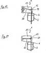
Bei dem in den
Im befestigten Zustand des Werkzeugträgers
Der Werkzeugträger
An dem Vorsprung
Die Führung des Seilzuges
Zwischen den beiden Vorsprüngen
Im Bereich der Löcher
In dem Basisteil
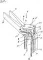
Das in den
Im Bereich der Löcher
Zur Führung der Seilzugabschnitte
BezugszeichenlisteLIST OF REFERENCE NUMBERS
- 22
- Schaft shaft
- 4, 4‘4, 4 '
- Instrumentenkopf instrument head
- 6, 6‘6, 6 '
- Verbindungsteil connecting part
- 8, 8‘8, 8 '
- Abschnitt section
- 10, 10‘10, 10 '
- Vorsprung head Start
- 1212
- Gelenkstift pintle
- 1414
- Aufnahmeloch receiving hole
- 1616
- Ausnehmung recess
- 17, 17‘17, 17 '
- Basisteil base
- 18, 18‘18, 18 '
- Schlitz slot
- 20, 20‘20, 20 '
- Radkörper Wheel center
- 2222
- Seilzug cable
- 2424
- Seilzugabschnitt cable section
- 2626
- Seilzugabschnitt cable section
- 2828
- Werkzeugträger tool carrier
- 3030
- Vorsprung head Start
- 3232
- Mittelteil midsection
- 3434
- Vorsprunghead Start
- 3636
- Vorsprung head Start
- 3838
- Flachseite flat side
- 4040
- Ausnehmung recess
- 4242
- Gelenkstift pintle
- 4444
- Durchgangsloch Through Hole
- 4646
- Ausnehmung recess
- 4848
- Loch hole
- 5050
- Stift pen
- 5252
- Radkörper Wheel center
- 5454
- Seilzug cable
- 5656
- Seilzugabschnitt cable section
- 5858
- Seilzugabschnitt cable section
- 6060
- Führungskanal guide channel
- 6262
- Führungskanalguide channel
- 6464
- Erweiterung extension
- 6666
- Maulteil jaw
- 6868
- Maulteil jaw
- 7070
- Gelenkstift pintle
- 7272
- Loch hole
- 7474
- Loch hole
- 7676
- Radkörper Wheel center
- 7878
- Seilzug cable
- 8080
- Umlenkrolle idler pulley
- 8282
- Gelenkstiftpintle
- 8484
- Seilzugabschnitt cable section
- 8686
- Seilzugabschnitt cable section
- 8888
- Führungskanal guide channel
- 9090
- Führungskanal guide channel
- 9292
- Erweiterung extension
- 9494
- Erweiterung extension
- 9696
- Vorsprung head Start
- 9898
- Gelenkstift pintle
- 100100
- Loch hole
- 102102
- Seilzug cable
- 104104
- Seilzugcable
- 106106
- Seilzugabschnitt cable section
- 108108
- Seilzugabschnitt cable section
- 110110
- Seilzugabschnitt cable section
- 112112
- Seilzugabschnitt cable section
- 114114
- Führungskanal guide channel
- 116116
- Führungskanal guide channel
- 118118
- Führungskanal guide channel
- 120120
- Führungskanal guide channel
- 122122
- Erweiterung extension
Claims (8)
Translated fromGermanPriority Applications (2)
| Application Number | Priority Date | Filing Date | Title |
|---|---|---|---|
| DE102013207248.1ADE102013207248A1 (en) | 2013-04-22 | 2013-04-22 | Instrument, in particular a medical endoscopic instrument or technoscope |
| PCT/DE2014/200162WO2014173409A1 (en) | 2013-04-22 | 2014-04-08 | Instrument, in particular a medical endoscopic instrument or technoscope |
Applications Claiming Priority (1)
| Application Number | Priority Date | Filing Date | Title |
|---|---|---|---|
| DE102013207248.1ADE102013207248A1 (en) | 2013-04-22 | 2013-04-22 | Instrument, in particular a medical endoscopic instrument or technoscope |
Publications (1)
| Publication Number | Publication Date |
|---|---|
| DE102013207248A1true DE102013207248A1 (en) | 2014-11-06 |
Family
ID=50841995
Family Applications (1)
| Application Number | Title | Priority Date | Filing Date |
|---|---|---|---|
| DE102013207248.1APendingDE102013207248A1 (en) | 2013-04-22 | 2013-04-22 | Instrument, in particular a medical endoscopic instrument or technoscope |
Country Status (2)
| Country | Link |
|---|---|
| DE (1) | DE102013207248A1 (en) |
| WO (1) | WO2014173409A1 (en) |
Cited By (1)
| Publication number | Priority date | Publication date | Assignee | Title |
|---|---|---|---|---|
| DE102015118914A1 (en)* | 2015-11-04 | 2017-05-04 | Gottfried Wilhelm Leibniz Universität Hannover | Working head for a medical-surgical manipulator and medical-surgical manipulator with such a working head |
Families Citing this family (2)
| Publication number | Priority date | Publication date | Assignee | Title |
|---|---|---|---|---|
| ITUB20154977A1 (en) | 2015-10-16 | 2017-04-16 | Medical Microinstruments S R L | Medical instrument and method of manufacture of said medical instrument |
| US10758298B2 (en) | 2017-01-20 | 2020-09-01 | Ethicon Llc | Articulating electrosurgical tools |
Citations (1)
| Publication number | Priority date | Publication date | Assignee | Title |
|---|---|---|---|---|
| US20120277762A1 (en)* | 2011-04-29 | 2012-11-01 | Lathrop Ray A | Dexterous surgical manipulator and method of use |
Family Cites Families (6)
| Publication number | Priority date | Publication date | Assignee | Title |
|---|---|---|---|---|
| US7699835B2 (en)* | 2001-02-15 | 2010-04-20 | Hansen Medical, Inc. | Robotically controlled surgical instruments |
| JP4287354B2 (en)* | 2004-10-25 | 2009-07-01 | 株式会社日立製作所 | Surgical instruments |
| KR101056204B1 (en)* | 2008-06-27 | 2011-08-11 | 정창욱 | Minimally invasive surgical instruments |
| US8540748B2 (en)* | 2008-07-07 | 2013-09-24 | Intuitive Surgical Operations, Inc. | Surgical instrument wrist |
| KR101056232B1 (en)* | 2008-09-12 | 2011-08-11 | 정창욱 | Minimally invasive surgical instruments and how to use them |
| DE102011011497A1 (en)* | 2011-02-17 | 2012-08-23 | Kuka Roboter Gmbh | Surgical instrument |
- 2013
- 2013-04-22DEDE102013207248.1Apatent/DE102013207248A1/enactivePending
- 2014
- 2014-04-08WOPCT/DE2014/200162patent/WO2014173409A1/enactiveApplication Filing
Patent Citations (1)
| Publication number | Priority date | Publication date | Assignee | Title |
|---|---|---|---|---|
| US20120277762A1 (en)* | 2011-04-29 | 2012-11-01 | Lathrop Ray A | Dexterous surgical manipulator and method of use |
Cited By (2)
| Publication number | Priority date | Publication date | Assignee | Title |
|---|---|---|---|---|
| DE102015118914A1 (en)* | 2015-11-04 | 2017-05-04 | Gottfried Wilhelm Leibniz Universität Hannover | Working head for a medical-surgical manipulator and medical-surgical manipulator with such a working head |
| DE102015118914B4 (en) | 2015-11-04 | 2019-07-04 | Gottfried Wilhelm Leibniz Universität Hannover | Working head for a medical-surgical manipulator |
Also Published As
| Publication number | Publication date |
|---|---|
| WO2014173409A1 (en) | 2014-10-30 |
Similar Documents
| Publication | Publication Date | Title |
|---|---|---|
| EP2510887B1 (en) | Tool for a micro-surgical instrument | |
| EP0609503B1 (en) | Medical instrument | |
| DE102004052204A1 (en) | Deflectible endoscopic instrument | |
| EP3076882A1 (en) | Instrument, in particular a medical endoscopic instrument or technoscope | |
| DE102014217796B4 (en) | Instrument, in particular medical-endoscopic instrument or technoscope | |
| DE102014205159A1 (en) | robot system | |
| EP3454769B1 (en) | Instrument, in particular medical endososcopic instrument | |
| WO2014124846A1 (en) | Instrument, in particular medical endoscopic instrument or technoscope | |
| DE102020211128A1 (en) | ENDOSCOPE WITH A FUNCTION TO PREVENT CHAIN JAMS | |
| EP2815707B1 (en) | Endoscopic instrument | |
| DE102012212094B4 (en) | Endoscopic instrument | |
| EP3272271A1 (en) | Adaptive laryngoscope and adaptive spatula for a laryngoscope | |
| EP3459473B1 (en) | Instrument | |
| DE102014219195B4 (en) | Instrument, in particular medical-endoscopic shaft instrument | |
| DE102013207248A1 (en) | Instrument, in particular a medical endoscopic instrument or technoscope | |
| DE102014206930B4 (en) | Instrument, in particular medical endoscopic instrument | |
| EP2601895A1 (en) | Medical instrument | |
| DE102015008872A1 (en) | Tongue-free jaw mechanism | |
| DE102015118914B4 (en) | Working head for a medical-surgical manipulator | |
| DE102013220019A1 (en) | Instrument, in particular a medical endoscopic instrument or technoscope | |
| DE102013114557A1 (en) | Medical instrument with flexible toothed belt | |
| DE102014218669A1 (en) | Instrument, in particular medical endoscopic instrument | |
| DE102013204677B4 (en) | endoscopic instrument | |
| DE102018116885A1 (en) | Deformable spatula for a laryngoscope | |
| DE102015103913A1 (en) | Hollow shaft instrument and in particular medical endoscopic hollow shaft instrument |
Legal Events
| Date | Code | Title | Description |
|---|---|---|---|
| R163 | Identified publications notified | ||
| R012 | Request for examination validly filed |