DE102013204726B4 - osteosynthesis - Google Patents
osteosynthesisDownload PDFInfo
- Publication number
- DE102013204726B4 DE102013204726B4DE102013204726.6ADE102013204726ADE102013204726B4DE 102013204726 B4DE102013204726 B4DE 102013204726B4DE 102013204726 ADE102013204726 ADE 102013204726ADE 102013204726 B4DE102013204726 B4DE 102013204726B4
- Authority
- DE
- Germany
- Prior art keywords
- clevis
- pressure piece
- wings
- ball head
- osteosynthesis device
- Prior art date
- Legal status (The legal status is an assumption and is not a legal conclusion. Google has not performed a legal analysis and makes no representation as to the accuracy of the status listed.)
- Active
Links
- 210000000988bone and boneAnatomy0.000claimsabstractdescription18
- 210000002414legAnatomy0.000claimsdescription11
- 210000000689upper legAnatomy0.000claimsdescription5
- 102000004315Forkhead Transcription FactorsHuman genes0.000abstractdescription15
- 108090000852Forkhead Transcription FactorsProteins0.000abstractdescription15
- 238000004873anchoringMethods0.000description1
- 230000001419dependent effectEffects0.000description1
- 238000002513implantationMethods0.000description1
Images


Classifications
- A—HUMAN NECESSITIES
- A61—MEDICAL OR VETERINARY SCIENCE; HYGIENE
- A61B—DIAGNOSIS; SURGERY; IDENTIFICATION
- A61B17/00—Surgical instruments, devices or methods
- A61B17/56—Surgical instruments or methods for treatment of bones or joints; Devices specially adapted therefor
- A61B17/58—Surgical instruments or methods for treatment of bones or joints; Devices specially adapted therefor for osteosynthesis, e.g. bone plates, screws or setting implements
- A61B17/68—Internal fixation devices, including fasteners and spinal fixators, even if a part thereof projects from the skin
- A61B17/70—Spinal positioners or stabilisers, e.g. stabilisers comprising fluid filler in an implant
- A61B17/7001—Screws or hooks combined with longitudinal elements which do not contact vertebrae
- A61B17/7035—Screws or hooks, wherein a rod-clamping part and a bone-anchoring part can pivot relative to each other
- A61B17/7037—Screws or hooks, wherein a rod-clamping part and a bone-anchoring part can pivot relative to each other wherein pivoting is blocked when the rod is clamped
Landscapes
- Health & Medical Sciences (AREA)
- Orthopedic Medicine & Surgery (AREA)
- Life Sciences & Earth Sciences (AREA)
- Neurology (AREA)
- Surgery (AREA)
- Heart & Thoracic Surgery (AREA)
- Engineering & Computer Science (AREA)
- Biomedical Technology (AREA)
- Nuclear Medicine, Radiotherapy & Molecular Imaging (AREA)
- Medical Informatics (AREA)
- Molecular Biology (AREA)
- Animal Behavior & Ethology (AREA)
- General Health & Medical Sciences (AREA)
- Public Health (AREA)
- Veterinary Medicine (AREA)
- Surgical Instruments (AREA)
Abstract
Translated fromGermanDescription
Translated fromGermanDie Erfindung betrifft eine Osteosynthesevorrichtung mit einer Knochenschraube mit einem eine Nut aufweisenden Gabelkopf mit zwei die Nut flankierenden Schenkeln, z.B. für einen in die Nut des Gabelkopfes zwischen die beiden Schenkel einzulegenden Verbindungsstab, und mit einem Gewindeschaft, der einen Kugelkopf aufweist, der im Gabelkopf verschwenkbar gelagert ist, und mit einem Druckstück, das auf dem Kugelkopf aufsitzt, wobei sich das Druckstück am Gabelkopf abstützt und zwei seitliche, in Achsrichtung des Gabelkopfes und weg vom Gewindeschaft sich erstreckende Flügel aufweist. Eine derartige Osteosynthesevorrichtung ist bekannt aus
Aus der
Die
Aus der
Weitere Osteosynthesevorrichtungen sind bekannt aus
Der Erfindung liegt die Aufgabe zugrunde, eine Osteosynthesevorrichtung der eingangs genannten Art derart weiterzubilden, dass der Gabelkopf und die Knochenschraube so eingestellt werden können, dass sie eine gewünschte Lage zueinander einnehmen und diese beibehalten, ohne dass der Verbindungsstab hierfür eingesetzt werden muss.The invention has the object of providing an osteosynthesis device of the type mentioned in such a way that the clevis and the bone screw can be adjusted so that they assume a desired position to each other and maintain this without the connecting rod must be used for this purpose.
Diese Aufgabe wird erfindungsgemäß mit einer Osteosynthesevorrichtung mit den Merkmalen des Anspruchs 1 gelöst.This object is achieved with an osteosynthesis device having the features of claim 1.
Die erfindungsgemäße Osteosynthesevorrichtung besitzt den wesentlichen Vorteil, dass die Knochenschraube und insbesondere deren teilkugelförmiger Kopf oder Kugelkopf, reibschlüssig oder kraftschlüssig im Gabelkopf gelagert ist, so dass die Knochenschraube vor dem Einschrauben in den Knochen in Bezug auf den Gabelkopf ausgerichtet werden kann. Der Gabelkopf kann in eine Lage gedreht oder verschwenkt werden, in welcher er das Einschrauben nicht stört oder behindert. Die erfindungsgemäße Osteosynthesevorrichtung erleichtert also die Implantation, die zudem schneller durchgeführt werden kann.The osteosynthesis device according to the invention has the significant advantage that the bone screw and in particular its part-spherical head or ball head, frictionally engaged or frictionally mounted in the clevis, so that the bone screw can be aligned with respect to the clevis before screwing into the bone. The clevis can be turned or pivoted into a position in which it does not interfere with or obstruct the screwing. The osteosynthesis device according to the invention thus facilitates the implantation, which moreover can be carried out more quickly.
Bei der Erfindung stützt sich das Druckstück am Gabelkopf ab. Es bedarf also keines Verbindungsstabes oder einer Schraubhülse, um das Druckstück unter Vorspannung zu setzen. Allein der korrekte Sitz im Gabelkopf gewährleistet den Reibschluss zwischen Knochenschraube und Gabelkopf, insbesondere an der Aufnahmekalotte des Gabelkopfes. Ferner wird ein Reibschluss zwischen dem Kugelkopf und dem Druckstück hergestellt.In the invention, the pressure piece is supported on the clevis. So it requires no connecting rod or a threaded sleeve to put the pressure piece under bias. Only the correct fit in the fork head ensures the frictional engagement between the bone screw and clevis, in particular on the receiving dome of the clevis. Furthermore, a frictional engagement between the ball head and the pressure piece is produced.
Dabei weist das Druckstück zwei seitliche, in Achsrichtung des Gabelkopfes und weg vom Gewindeschaft sich erstreckende Flügel auf. Diese Flügel erstrecken sich bei in den Gabelkopf eingesetztem Druckstück parallel zu den Schenkeln des Gabelkopfes. Eine der Aufgaben der Flügel besteht darin, das Druckstück mit dem Gabelkopf zu verbinden, so dass Kräfte zwischen dem Druckstück und dem Gabelkopf übertragen werden können. Dabei sollen Kräfte in Längsrichtung der Knochenschraube übertragen werden, d.h. Kräfte koaxial zur Achse der Kalotte des Gabelkopfes. Die Flügel bilden dabei Federn, die das Druckstück auf den Kugelkopf drücken.In this case, the pressure piece on two lateral, in the axial direction of the clevis and away from the threaded shank extending wings. These wings extend parallel to the legs of the fork head inserted in the fork head pressure piece. One of the tasks of the wings is to connect the pressure piece with the fork head, so that forces between the pressure piece and the clevis can be transmitted. In this case, forces are to be transmitted in the longitudinal direction of the bone screw, i. Forces coaxial to the axis of the dome of the fork head. The wings form springs that press the pressure piece on the ball head.
Eine vorteilhafte Weiterbildung der Erfindung sieht vor, dass an der den Schenkeln zugewandten Außenseiten der Flügel Ausnehmungen oder Vorsprünge vorgesehen sind, die in Vorsprünge oder Ausnehmungen eingreifen, welche an den Innenflächen der Schenkel des Gabelkopfes vorgesehen sind. Hierdurch wird eine einfache Möglichkeit geschaffen, das Druckstück mit dem Gabelkopf zu verbinden. An Stelle von Vorsprüngen und Ausnehmungen können auch entsprechende Schultern an den Bauteilen dienen, so dass das Druckstück einen an der Innenfläche eines jeden Schenkels vorgesehenen Vorsprung untergreift.An advantageous development of the invention provides that at the legs facing the outer sides of the wings recesses or projections are provided which engage in projections or recesses which are provided on the inner surfaces of the legs of the clevis. This provides a simple way to connect the pressure piece with the clevis. Instead of projections and recesses can also serve corresponding shoulders on the components, so that the pressure piece engages under a provided on the inner surface of each leg projection.
Ein erfindungsgemäßes Merkmal ist, dass wenigstens einer der Flügel quer zur Achsrichtung des Gabelkopfes geschlitzt ist. Der Schlitz kann einseitig offen oder beidseitig geschlossen sein. Durch die Schlitze, die quer zur Längsrichtung der Knochenschraube verlaufen, wird in den Flügeln eine gewisse Elastizität in der Längsrichtung erzeugt, so dass das Druckstück unter Vorspannung im Gabelkopf verankert werden kann, indem die Flügel geringfügig in deren Längsrichtung komprimiert werden.An inventive feature is that at least one of the wings is slotted transversely to the axial direction of the clevis. The slot can be open on one side or closed on both sides. Through the slots, which extend transversely to the longitudinal direction of the bone screw, a certain elasticity is generated in the longitudinal direction in the wings, so that the pressure piece can be anchored under prestress in the clevis by the wings are slightly compressed in the longitudinal direction.
Eine vorteilhafte Weiterbildung der Erfindung sieht vor, dass jeder Flügel mehrere Schlitze aufweist, die abwechselnd von der einen Seite und von der anderen Seite quer zur Achsrichtung des Gabelkopfes in den Flügel einschneiden. Hierdurch kann die Elastizität der Flügel auch auf kurzen Wegen und großen Wandstärken einfach eingestellt werden. Die Flügel können auch bogenförmig oder henkelförmig ausgebildet sein, so dass sich der Scheitelpunkt des Bogens an dem jeweils radial nach innen ragenden Vorsprung des Gabelkopfes abstützt. An advantageous development of the invention provides that each wing has a plurality of slots which cut alternately from one side and from the other side transversely to the axial direction of the clevis in the wing. As a result, the elasticity of the wings can be easily adjusted even on short distances and large wall thicknesses. The wings may also be arcuate or handle-shaped, so that the vertex of the arc is supported on the respective radially inwardly projecting projection of the fork head.
Eine Weiterbildung der Erfindung sieht vor, dass das Druckstück ein Auflager für den Verbindungsstab bildet. Der Verbindungsstab sitzt also direkt auf dem Druckstück auf und drückt dieses nach dem Fixieren des Verbindungsstabes zusätzlich auf den Gabelkopf. Die im Druckstück enthaltene Feder hat dann praktisch keine Funktion mehr.A development of the invention provides that the pressure piece forms a support for the connecting rod. The connecting rod thus sits directly on the pressure piece and presses this after fixing the connecting rod in addition to the clevis. The spring contained in the pressure piece then has virtually no function.
Weitere Vorteile, Merkmale und Einzelheiten der Erfindung ergeben sich aus den Unteransprüchen sowie der nachfolgenden Beschreibung, in der unter Bezugnahme auf die Zeichnung besonders bevorzugte Ausführungsbeispiele im Einzelnen beschrieben sind.Further advantages, features and details of the invention will become apparent from the dependent claims and the following description in which with reference to the drawings particularly preferred embodiments are described in detail.
In der Zeichnung zeigen:In the drawing show:
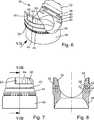
Die
Die
Die
In den
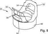
Weiterhin zeigt die
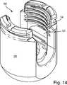
Schließlich ist in der
Nachdem die Knochenschraube
Ist das Druckstück
Claims (6)
Translated fromGermanPriority Applications (1)
| Application Number | Priority Date | Filing Date | Title |
|---|---|---|---|
| DE102013204726.6ADE102013204726B4 (en) | 2013-03-18 | 2013-03-18 | osteosynthesis |
Applications Claiming Priority (1)
| Application Number | Priority Date | Filing Date | Title |
|---|---|---|---|
| DE102013204726.6ADE102013204726B4 (en) | 2013-03-18 | 2013-03-18 | osteosynthesis |
Publications (2)
| Publication Number | Publication Date |
|---|---|
| DE102013204726A1 DE102013204726A1 (en) | 2014-09-18 |
| DE102013204726B4true DE102013204726B4 (en) | 2017-08-10 |
Family
ID=51418859
Family Applications (1)
| Application Number | Title | Priority Date | Filing Date |
|---|---|---|---|
| DE102013204726.6AActiveDE102013204726B4 (en) | 2013-03-18 | 2013-03-18 | osteosynthesis |
Country Status (1)
| Country | Link |
|---|---|
| DE (1) | DE102013204726B4 (en) |
Families Citing this family (10)
| Publication number | Priority date | Publication date | Assignee | Title |
|---|---|---|---|---|
| US8444681B2 (en) | 2009-06-15 | 2013-05-21 | Roger P. Jackson | Polyaxial bone anchor with pop-on shank, friction fit retainer and winged insert |
| US10792074B2 (en) | 2007-01-22 | 2020-10-06 | Roger P. Jackson | Pivotal bone anchor assemly with twist-in-place friction fit insert |
| US11229457B2 (en) | 2009-06-15 | 2022-01-25 | Roger P. Jackson | Pivotal bone anchor assembly with insert tool deployment |
| US12383311B2 (en) | 2010-05-14 | 2025-08-12 | Roger P. Jackson | Pivotal bone anchor assembly and method for use thereof |
| US8911479B2 (en) | 2012-01-10 | 2014-12-16 | Roger P. Jackson | Multi-start closures for open implants |
| US10064658B2 (en) | 2014-06-04 | 2018-09-04 | Roger P. Jackson | Polyaxial bone anchor with insert guides |
| US11219471B2 (en) | 2014-10-21 | 2022-01-11 | Roger P. Jackson | Pivotal bone anchor receiver having an insert with post-placement tool deployment |
| US10543021B2 (en) | 2014-10-21 | 2020-01-28 | Roger P. Jackson | Pivotal bone anchor assembly having an open ring positioner for a retainer |
| US11596449B2 (en) | 2018-09-13 | 2023-03-07 | Roger P. Jackson | Pivotal bone anchor assembly with modular receiver and universal shank head |
| US11751915B2 (en) | 2021-07-09 | 2023-09-12 | Roger P. Jackson | Modular spinal fixation system with bottom-loaded universal shank heads |
Citations (3)
| Publication number | Priority date | Publication date | Assignee | Title |
|---|---|---|---|---|
| US20060241599A1 (en)* | 2003-06-27 | 2006-10-26 | Konieczynski David D | Polyaxial Bone Screw |
| DE602005002477T2 (en)* | 2005-07-12 | 2008-01-17 | Biedermann Motech Gmbh | Bone anchoring device |
| US20110077694A1 (en)* | 2009-09-25 | 2011-03-31 | Lutz Biedermann | Bone anchoring device |
Family Cites Families (3)
| Publication number | Priority date | Publication date | Assignee | Title |
|---|---|---|---|---|
| DE19617362C2 (en) | 1996-04-30 | 1999-06-10 | Harms Juergen | Anchoring element |
| DE10164323C1 (en) | 2001-12-28 | 2003-06-18 | Biedermann Motech Gmbh | Bone screw has holder element joined to shaft and possessing two free arms , with inner screw, slot, external nut, cavity and shoulder cooperating with attachment |
| DE10320417A1 (en) | 2003-05-07 | 2004-12-02 | Biedermann Motech Gmbh | Dynamic anchoring device and dynamic stabilization device for bones, in particular for vertebrae, with such an anchoring device |
- 2013
- 2013-03-18DEDE102013204726.6Apatent/DE102013204726B4/enactiveActive
Patent Citations (3)
| Publication number | Priority date | Publication date | Assignee | Title |
|---|---|---|---|---|
| US20060241599A1 (en)* | 2003-06-27 | 2006-10-26 | Konieczynski David D | Polyaxial Bone Screw |
| DE602005002477T2 (en)* | 2005-07-12 | 2008-01-17 | Biedermann Motech Gmbh | Bone anchoring device |
| US20110077694A1 (en)* | 2009-09-25 | 2011-03-31 | Lutz Biedermann | Bone anchoring device |
Also Published As
| Publication number | Publication date |
|---|---|
| DE102013204726A1 (en) | 2014-09-18 |
Similar Documents
| Publication | Publication Date | Title |
|---|---|---|
| DE102013204726B4 (en) | osteosynthesis | |
| EP1316294B1 (en) | Fastener assembly for securing a rod-shaped element in a retaining element connected to a shaft | |
| DE69831188T2 (en) | pedicle screw | |
| EP1323391B1 (en) | Locking device for securing a rod in a holder, especially of a polyaxial bone screw | |
| EP1579816B1 (en) | Enchoring element and dynamic stabilisation device for vertebral bodies or bones | |
| DE60212632T2 (en) | FIXING DEVICE FOR FIXING SPINE PARTS | |
| DE69830499T2 (en) | DEVICE FOR OSTEOSYNTHESIS WITH A CONNECTING ELEMENT BETWEEN THE SWIVEL ROD AND ANCHORING ELEMENTS | |
| EP2858585B1 (en) | Bone screw arrangement with variable length | |
| DE102016108504A1 (en) | Medical instrument for temporary fixation of a polyaxial pedicle screw | |
| WO2017194633A1 (en) | Pedicle screw with large-diameter bone thread | |
| DE10152094A1 (en) | Bone fixation device | |
| EP1274356A1 (en) | Device for fixing implants on or in a bone | |
| EP2460484A1 (en) | Variable angle bone screw fixation assembly | |
| CH615821A5 (en) | ||
| EP3215039B1 (en) | Osteosynthesis device | |
| WO2011083093A1 (en) | Trampoline | |
| EP3100691A1 (en) | Uniplanar bone anchoring element | |
| DE102017120619B4 (en) | Extension device for a bone screw and screwdriver instrument | |
| DE102017116755A1 (en) | Bone anchor for triangular iliosacral osteosynthesis | |
| DE102017124734B4 (en) | polyaxial screw | |
| DE102016115181A1 (en) | plumbing fixture | |
| EP3331461B1 (en) | Handling instrument for a bone anchor | |
| DE19826380B4 (en) | Osteosynthetic attachment system | |
| DE10234603B4 (en) | Clamping device for tools or workpieces | |
| WO2014122210A1 (en) | Osteosynthesis device |
Legal Events
| Date | Code | Title | Description |
|---|---|---|---|
| R012 | Request for examination validly filed | ||
| R082 | Change of representative | Representative=s name:DREISS PATENTANWAELTE PARTG MBB, DE | |
| R016 | Response to examination communication | ||
| R016 | Response to examination communication | ||
| R018 | Grant decision by examination section/examining division | ||
| R020 | Patent grant now final |