DE102013203545A1 - A switch failure detection device and method for detecting a failure of an electronic switch - Google Patents
A switch failure detection device and method for detecting a failure of an electronic switchDownload PDFInfo
- Publication number
- DE102013203545A1 DE102013203545A1DE201310203545DE102013203545ADE102013203545A1DE 102013203545 A1DE102013203545 A1DE 102013203545A1DE 201310203545DE201310203545DE 201310203545DE 102013203545 ADE102013203545 ADE 102013203545ADE 102013203545 A1DE102013203545 A1DE 102013203545A1
- Authority
- DE
- Germany
- Prior art keywords
- voltage
- electronic switch
- switch
- input
- command signal
- Prior art date
- Legal status (The legal status is an assumption and is not a legal conclusion. Google has not performed a legal analysis and makes no representation as to the accuracy of the status listed.)
- Granted
Links
Images


Classifications
- G—PHYSICS
- G01—MEASURING; TESTING
- G01R—MEASURING ELECTRIC VARIABLES; MEASURING MAGNETIC VARIABLES
- G01R31/00—Arrangements for testing electric properties; Arrangements for locating electric faults; Arrangements for electrical testing characterised by what is being tested not provided for elsewhere
- G01R31/327—Testing of circuit interrupters, switches or circuit-breakers
- G01R31/3277—Testing of circuit interrupters, switches or circuit-breakers of low voltage devices, e.g. domestic or industrial devices, such as motor protections, relays, rotation switches
- G—PHYSICS
- G01—MEASURING; TESTING
- G01R—MEASURING ELECTRIC VARIABLES; MEASURING MAGNETIC VARIABLES
- G01R31/00—Arrangements for testing electric properties; Arrangements for locating electric faults; Arrangements for electrical testing characterised by what is being tested not provided for elsewhere
- G01R31/36—Arrangements for testing, measuring or monitoring the electrical condition of accumulators or electric batteries, e.g. capacity or state of charge [SoC]
- H—ELECTRICITY
- H01—ELECTRIC ELEMENTS
- H01M—PROCESSES OR MEANS, e.g. BATTERIES, FOR THE DIRECT CONVERSION OF CHEMICAL ENERGY INTO ELECTRICAL ENERGY
- H01M10/00—Secondary cells; Manufacture thereof
- H01M10/42—Methods or arrangements for servicing or maintenance of secondary cells or secondary half-cells
- H—ELECTRICITY
- H02—GENERATION; CONVERSION OR DISTRIBUTION OF ELECTRIC POWER
- H02J—CIRCUIT ARRANGEMENTS OR SYSTEMS FOR SUPPLYING OR DISTRIBUTING ELECTRIC POWER; SYSTEMS FOR STORING ELECTRIC ENERGY
- H02J7/00—Circuit arrangements for charging or depolarising batteries or for supplying loads from batteries
- H02J7/0029—Circuit arrangements for charging or depolarising batteries or for supplying loads from batteries with safety or protection devices or circuits
- H02J7/0031—Circuit arrangements for charging or depolarising batteries or for supplying loads from batteries with safety or protection devices or circuits using battery or load disconnect circuits
- G—PHYSICS
- G01—MEASURING; TESTING
- G01R—MEASURING ELECTRIC VARIABLES; MEASURING MAGNETIC VARIABLES
- G01R31/00—Arrangements for testing electric properties; Arrangements for locating electric faults; Arrangements for electrical testing characterised by what is being tested not provided for elsewhere
- G01R31/327—Testing of circuit interrupters, switches or circuit-breakers
- G01R31/3277—Testing of circuit interrupters, switches or circuit-breakers of low voltage devices, e.g. domestic or industrial devices, such as motor protections, relays, rotation switches
- G01R31/3278—Testing of circuit interrupters, switches or circuit-breakers of low voltage devices, e.g. domestic or industrial devices, such as motor protections, relays, rotation switches of relays, solenoids or reed switches
- H—ELECTRICITY
- H02—GENERATION; CONVERSION OR DISTRIBUTION OF ELECTRIC POWER
- H02J—CIRCUIT ARRANGEMENTS OR SYSTEMS FOR SUPPLYING OR DISTRIBUTING ELECTRIC POWER; SYSTEMS FOR STORING ELECTRIC ENERGY
- H02J7/00—Circuit arrangements for charging or depolarising batteries or for supplying loads from batteries
- H02J7/0029—Circuit arrangements for charging or depolarising batteries or for supplying loads from batteries with safety or protection devices or circuits
- H02J7/00302—Overcharge protection
- H—ELECTRICITY
- H02—GENERATION; CONVERSION OR DISTRIBUTION OF ELECTRIC POWER
- H02J—CIRCUIT ARRANGEMENTS OR SYSTEMS FOR SUPPLYING OR DISTRIBUTING ELECTRIC POWER; SYSTEMS FOR STORING ELECTRIC ENERGY
- H02J7/00—Circuit arrangements for charging or depolarising batteries or for supplying loads from batteries
- H02J7/0029—Circuit arrangements for charging or depolarising batteries or for supplying loads from batteries with safety or protection devices or circuits
- H02J7/00306—Overdischarge protection
- Y—GENERAL TAGGING OF NEW TECHNOLOGICAL DEVELOPMENTS; GENERAL TAGGING OF CROSS-SECTIONAL TECHNOLOGIES SPANNING OVER SEVERAL SECTIONS OF THE IPC; TECHNICAL SUBJECTS COVERED BY FORMER USPC CROSS-REFERENCE ART COLLECTIONS [XRACs] AND DIGESTS
- Y02—TECHNOLOGIES OR APPLICATIONS FOR MITIGATION OR ADAPTATION AGAINST CLIMATE CHANGE
- Y02E—REDUCTION OF GREENHOUSE GAS [GHG] EMISSIONS, RELATED TO ENERGY GENERATION, TRANSMISSION OR DISTRIBUTION
- Y02E60/00—Enabling technologies; Technologies with a potential or indirect contribution to GHG emissions mitigation
- Y02E60/10—Energy storage using batteries
Landscapes
- Physics & Mathematics (AREA)
- General Physics & Mathematics (AREA)
- Engineering & Computer Science (AREA)
- Power Engineering (AREA)
- Chemical Kinetics & Catalysis (AREA)
- Chemical & Material Sciences (AREA)
- Manufacturing & Machinery (AREA)
- Electrochemistry (AREA)
- General Chemical & Material Sciences (AREA)
- Charge And Discharge Circuits For Batteries Or The Like (AREA)
- Testing Of Individual Semiconductor Devices (AREA)
- Secondary Cells (AREA)
- Protection Of Static Devices (AREA)
- Microelectronics & Electronic Packaging (AREA)
Abstract
Translated fromGermanDescription
Translated fromGermanTechnisches GebietTechnical area
Die in dieser Beschreibung beschriebene Technik betrifft das Erfassen eines Ausfalls eines Schalters, der konfiguriert ist, um Lade- oder Entladeströme zu sperren.The technique described in this specification relates to detecting a failure of a switch configured to disable charging or discharging currents.
Stand der TechnikState of the art
Eine elektrische Speichereinrichtung wie etwa eine Lithium-Ionen-Batterie kann aufgrund von Variationen in der Kapazität zwischen Zellen oder eines Ausfalls einer externen Einrichtung wie etwa eines Ladegeräts oder einer Last überladen oder überentladen werden. Deshalb kann ein bekannter Batteriepack eine Überladungs-/Überentladungsschutzfunktion umfassen. Ein derartiger Batteriepack kann einen elektronischen Schalter wie etwa einen FET und eine Überwachungseinheit umfassen. Der Schalter ist in einem Strompfad verbunden, in dem ein Ladestrom oder ein Entladestrom fließt. Die Überwachungseinheit ist konfiguriert, um eine Anschlussspannung der elektrischen Speichereinrichtung zu messen. Wenn die Anschlussspannung einen vorbestimmten Pegel während des Ladens der elektrischen Speichereinrichtung erreicht, wird der Schalter ausgeschaltet, um den Ladestrom zu sperren, sodass die elektrische Speichereinrichtung gegen eine Überladung geschützt wird.An electric storage device such as a lithium-ion battery may be over-charged or over-discharged due to variations in the capacity between cells or failure of an external device such as a charger or a load. Therefore, a known battery pack may include an overcharge / over-discharge protection function. Such a battery pack may include an electronic switch such as a FET and a monitoring unit. The switch is connected in a current path in which a charging current or a discharge current flows. The monitoring unit is configured to measure a terminal voltage of the electrical storage device. When the terminal voltage reaches a predetermined level during the charging of the electrical storage device, the switch is turned off to block the charging current, so that the electrical storage device is protected against overcharging.
Ein bekannter Batteriepack mit einer Schutzfunktion kann die folgende Konfiguration aufweisen. Wenn eine Spannung zwischen einem Eingang und einem Ausgang eines elektronischen Schalters und damit ein Spannungsabfall während des Ladens groß ist, wird ein anormaler Zustand bestimmt, in welchem ein Ein-Widerstand aufgrund eines Ausfalls des Schalters übermäßig hoch ist. Wenn der anormale Zustand bestimmt wird, wird der Schalter ausgeschaltet, um eine Batterie zu deaktivieren.A known battery pack with a protective function may have the following configuration. When a voltage between an input and an output of an electronic switch and thus a voltage drop during charging is large, an abnormal state is determined in which an on-resistance due to a failure of the switch is excessively high. When the abnormal condition is determined, the switch is turned off to deactivate a battery.
Ein Beispiel für einen derartigen Batteriepack ist in dem Patentdokument Nr.
In einem derartigen Batteriepack kann der Schalter nicht ausgeschaltet werden, wenn aus irgendeinem Grund ein Kurzschluss zwischen dem Eingang und dem Ausgang des Schalters auftritt. Wenn der Schalter nicht ausgeschaltet werden kann, kann die Schutzfunktion nicht korrekt durchgeführt werden. Daraus resultiert, dass die elektrische Speichereinrichtung überladen oder überentladen werden kann. Also auch wenn ein anormaler Zustand des Schalters erfasst wird, kann die Batterie nicht deaktiviert werden, weil der Schalter nicht ausgeschaltet werden kann.In such a battery pack, the switch can not be turned off if for any reason a short circuit occurs between the input and the output of the switch. If the switch can not be turned off, the protection function can not be performed correctly. As a result, the electrical storage device may be overcharged or overdischarged. So even if an abnormal condition of the switch is detected, the battery can not be disabled because the switch can not be turned off.
Ein Ausschaltproblem des Schalters kann zuvor erfasst werden, indem der Schalter von Ein zu Aus geschaltet wird. Jedoch kann die Stromversorgung zu einer Last gestoppt werden, wenn die Schalterausfallerfassung in dieser Form auf einem Entladestrom-Sperrschalter während des Entladens durchgeführt wird. Wenn die Schalterausfallerfassung auf einem Ladestrom-Sperrschalter während des Ladens durchgeführt wird, kann die Stromversorgung zu der elektrischen Speichereinrichtung gestoppt werden.A switch-off problem of the switch can be detected beforehand by switching the switch from on to off. However, the power supply to a load may be stopped when the switch failure detection in this form is performed on a discharge current cutoff switch during discharging. When the switch failure detection is performed on a charging current cut-off switch during charging, the power supply to the electric storage device can be stopped.
Gemäß einer in dieser Beschreibung beschriebenen Technik kann eine Schalterausfallerfassung durchgeführt werden, während eine Stromversorgung zu einer elektrischen Speichereinrichtung oder von der elektrischen Speichereinrichtung aufrechterhalten wird.According to a technique described in this specification, a switch failure detection can be performed while maintaining a power supply to an electric storage device or from the electric storage device.
ZusammenfassungSummary
Eine Schalterausfall-Erfassungsvorrichtung kann in einem elektrischen System installiert werden, das eine elektrische Speichereinrichtung enthält. Die Schalterausfall-Erfassungsvorrichtung umfasst wenigstens einen elektronischen Schalter, wenigstens einen Gleichrichter, eine Schalterspannungs-Erfassungsschaltung und eine Steuereinrichtung.A switch failure detection device may be installed in an electrical system including an electrical storage device. The switch failure detection device comprises at least one electronic switch, at least one rectifier, a switch voltage detection circuit, and a controller.
Der elektronische Schalter ist in einem Pfad zu verbinden, in dem ein Ladestrom zu der elektrischen Speichereinrichtung und ein Entladestrom von der elektrischen Speichereinrichtung fließen. Der elektronische Schalter wird zwischen Ein und Aus geschaltet. Der Gleichrichter ist konfiguriert, um einen Entladestrom durchzulassen, indem er den elektronischen Schalter umgeht, wenn der elektronische Schalter ausgeschaltet ist. Die Schalterspannungs-Erfassungsschaltung ist konfiguriert, um eine Spannung zwischen einem Eingang und einem Ausgang des elektronischen Schalters zu erfassen.The electronic switch is to be connected in a path in which a charging current flows to the electric storage device and a discharge current from the electric storage device. The electronic switch is switched between on and off. The rectifier is configured to pass a discharge current by bypassing the electronic switch when the electronic switch is turned off. The switch voltage detection circuit is configured to detect a voltage between an input and an output of the electronic switch.
Die Steuereinrichtung ist konfiguriert zum: Bestimmen, ob sich die elektrische Speichereinrichtung in einem Entladezustand befindet; Senden eines Aus-Befehlssignals zu dem elektronischen Schalter, um den elektronischen Schalter auszuschalten, wenn sich die elektrische Speichereinrichtung in dem Entladezustand befindet; Empfangen der durch die Schalterspannungs-Erfassungsschaltung erfassten Spannung, während das Aus-Befehlssignal zu dem elektronischen Schalter gesendet wird; Bestimmen einer Eingang-Ausgang-Spannung des elektronischen Schalters auf der Basis der Spannung; Bestimmen, ob die Eingang-Ausgang-Spannung niedriger als eine Bezugsspannung ist; und Bestimmen, dass der elektronische Schalter ein Ausschaltproblem aufweist, in dem der elektronische Schalter nicht in Übereinstimmung mit dem Aus-Befehlssignal ausgeschaltet wird, wenn die Eingang-Ausgang-Spannung niedriger als die Bezugsspannung ist.The controller is configured to: determine whether the electrical storage device is in a discharge state; Sending an off command signal to the electronic switch to turn off the electronic switch when the electrical storage device is in the discharge state; Receiving the voltage detected by the switch voltage detection circuit while the off-command signal is being sent to the electronic switch; Determining an input-output voltage of the electronic switch based on the voltage; Determining if the input-output voltage is lower than a reference voltage; and determining that the electronic switch has a turn-off problem in which the electronic switch is not in accordance with the off-command signal is turned off when the input-output voltage is lower than the reference voltage.
Mit dieser Konfiguration fließt der Entladestrom auch dann weiterhin von der elektrischen Speichereinrichtung zu einer Last über den Gleichrichter, wenn der elektronische Schalter ausgeschaltet ist. Die Schalterausfallerfassung kann nämlich durchgeführt werden, während die Stromversorgung zu der Last aufrechterhalten wird.With this configuration, the discharge current continues to flow from the electric storage device to a load via the rectifier even when the electronic switch is turned off. Namely, the switch failure detection can be performed while the power supply to the load is maintained.
Der wenigstens eine elektronische Schalter umfasst einen ersten elektronischen Schalter und einen zweiten elektronischen Schalter. Der wenigstens eine Gleichrichter umfasst einen ersten Gleichrichter und einen zweiten Gleichrichter. Der erste Gleichrichter ist parallel mit dem ersten elektronischen Schalter verbunden, sodass seine Vorwärtsrichtung der Flussrichtung des Entladestroms entspricht. Der zweite Gleichrichter ist parallel mit dem zweiten elektronischen Schalter verbunden, sodass seine Vorwärtsrichtung der Flussrichtung des Ladestroms entspricht. Die Spannungserfassungsschaltung ist weiterhin konfiguriert, um eine erste Spannung zwischen einem Eingang und einem Ausgang des ersten elektronischen Schalters und eine zweite Spannung zwischen einem Eingang und einem Ausgang des zweiten elektronischen Schalters zu erfassen.The at least one electronic switch comprises a first electronic switch and a second electronic switch. The at least one rectifier comprises a first rectifier and a second rectifier. The first rectifier is connected in parallel with the first electronic switch, so that its forward direction corresponds to the flow direction of the discharge current. The second rectifier is connected in parallel with the second electronic switch, so that its forward direction corresponds to the direction of flow of the charging current. The voltage detection circuit is further configured to detect a first voltage between an input and an output of the first electronic switch and a second voltage between an input and an output of the second electronic switch.
Die Steuereinrichtung ist weiterhin konfiguriert zum: Senden des Aus-Befehlssignals zu dem ersten elektronischen Schalter und eines Ein-Befehlssignals zu dem zweiten elektronischen Schalter, um den zweiten elektronischen Schalter einzuschalten, wenn sich die elektrische Speichereinrichtung in dem Entladezustand befindet; Senden eines Ein-Befehlssignals zu dem ersten elektronischen Schalter, um den ersten elektronischen Schalter einzuschalten, und des Aus-Befehlssignals zu dem zweiten elektronischen Schalter, wenn sich die elektrische Speichereinrichtung in dem Ladezustand befindet; Empfangen der durch die Schalterspannungs-Erfassungsschaltung erfassten ersten Spannung, während das Aus-Befehlssignal zu dem ersten elektronischen Schalter gesendet wird; Bestimmen einer ersten Eingang-Ausgang-Spannung auf der Basis der ersten Spannung; Bestimmen, ob die erste Eingang-Ausgang-Spannung niedriger als die erste Bezugsspannung ist; Bestimmen, dass der erste elektronische Schalter ein Ausschaltproblem aufweist, in dem der erste elektronische Schalter nicht in Übereinstimmung mit dem zu dem ersten elektronischen Schalter gesendeten Aus-Befehlssignal ausgeschaltet wird, wenn die erste Eingang-Ausgang-Spannung niedriger als die erste Bezugsspannung ist; Empfangen der durch die Schalterspannungs-Erfassungsschaltung erfassten zweiten Spannung, während das Aus-Befehlssignal zu dem zweiten elektronischen Schalter gesendet wird; Bestimmen einer zweiten Eingang-Ausgang-Spannung auf der Basis der zweiten Spannung; Bestimmen, ob die zweite Eingang-Ausgang-Spannung niedriger als die erste Bezugsspannung ist; und Bestimmen, dass der zweite elektronische Schalter ein Ausschaltproblem aufweist, in dem der zweite elektronische Schalter nicht in Übereinstimmung mit dem zu dem zweiten elektronischen Schalter gesendeten Aus-Befehlssignal ausgeschaltet wird, wenn die zweite Eingang-Ausgang-Spannung niedriger als die erste Bezugsspannung ist.The controller is further configured to: send the off command signal to the first electronic switch and an on command signal to the second electronic switch to turn on the second electronic switch when the electrical storage device is in the discharge state; Sending an on command signal to the first electronic switch to turn on the first electronic switch and the off command signal to the second electronic switch when the electrical storage device is in the state of charge; Receiving the first voltage detected by the switch voltage detection circuit while the off-command signal is being sent to the first electronic switch; Determining a first input-output voltage based on the first voltage; Determining if the first input-output voltage is lower than the first reference voltage; Determining that the first electronic switch has a turn-off problem in which the first electronic switch is not turned off in accordance with the off-command signal sent to the first electronic switch when the first input-output voltage is lower than the first reference voltage; Receiving the second voltage detected by the switch voltage detection circuit while the off-command signal is being sent to the second electronic switch; Determining a second input-output voltage based on the second voltage; Determining if the second input-output voltage is lower than the first reference voltage; and determining that the second electronic switch has a turn-off problem in which the second electronic switch is not turned off in accordance with the off-command signal sent to the second electronic switch when the second input-output voltage is lower than the first reference voltage.
Mit dieser Konfiguration kann die Schalterausfallerfassung durch eine Ein-Aus-Steuerung des ersten und des zweiten elektronischen Schalters durchgeführt werden, wenn sich die elektrische Speichereinrichtung in dem Ladezustand oder in dem Entladezustand befindet. Im Vergleich zu einer Konfiguration, in welcher der erste und der zweite elektronische Schalter in verschiedenen Pfaden vorgesehen sind, kann die Anzahl der elektrischen Leitungen oder Überwachungseinrichtungen reduziert werden, sodass die Schalterausfall-Erfassungsvorrichtung mit einem einfachen Aufbau versehen werden kann.With this configuration, the switch failure detection can be performed by on-off control of the first and second electronic switches when the electric storage device is in the state of charge or in the discharge state. As compared with a configuration in which the first and second electronic switches are provided in different paths, the number of electric wires or monitoring devices can be reduced, so that the switch failure detection device can be provided with a simple structure.
Der elektronische Schalter ist in einem Pfad zu verbinden, in dem ein Ladestrom und ein Enltadestrom fließen, und wird zwischen Ein und Aus geschaltet. Der Gleichrichter ist parallel zu dem elektronischen Schalter verbunden, sodass seine Vorwärtsrichtung der Flussrichtung des Ladestroms entspricht. Die Schalterspannungs-Erfassungsschaltung ist konfiguriert, um eine Spannung zwischen einem Eingang und einem Ausgang des elektronischen Schalters zu erfassen.The electronic switch is to be connected in a path in which a charging current and an Enltadestrom flow, and is switched between on and off. The rectifier is connected in parallel to the electronic switch, so that its forward direction corresponds to the direction of flow of the charging current. The switch voltage detection circuit is configured to detect a voltage between an input and an output of the electronic switch.
Die Steuereinrichtung ist konfiguriert zum: Bestimmen, ob sich die elektrische Speichereinrichtung in einem Ladezustand befindet; Senden eines Aus-Befehlssignals zu dem elektronischen Schalter, um den elektronischen Schalter auszuschalten, wenn sich die elektrische Speichereinrichtung in dem Ladezustand befindet; Empfangen der durch die Schalterspannungs-Erfassungsschaltung erfassten Spannung, während das Aus-Befehlssignal zu dem elektronischen Schalter gesendet wird; Bestimmen einer Eingang-Ausgang-Spannung des elektronischen Schalters auf der Basis der Spannung; Bestimmen, ob die Eingang-Ausgang-Spannung niedriger als eine erste Bezugsspannung ist; und Bestimmen, dass der elektronische Schalter ein Ausschaltproblem aufweist, in dem der elektronische Schalter nicht in Übereinstimmung mit dem Aus-Befehlssignal ausgeschaltet wird, wenn die Eingang-Ausgang-Spannung niedriger als die erste Bezugsspannung ist.The controller is configured to: determine whether the electrical storage device is in a state of charge; Sending an off command signal to the electronic switch to turn off the electronic switch when the electrical storage device is in the state of charge; Receiving the voltage detected by the switch voltage detection circuit while the off-command signal is being sent to the electronic switch; Determining an input-output voltage of the electronic switch based on the voltage; Determining if the input-output voltage is lower than a first reference voltage; and determining that the electronic switch has a turn-off problem in which the electronic switch is not turned off in accordance with the off-command signal when the input-output voltage is lower than the first reference voltage.
Mit dieser Konfiguration fließt der Ladestrom auch dann weiterhin zu der elektrischen Speichereinrichtung über den Gleichrichter, wenn der elektronische Schalter ausgeschaltet ist. Die Schalterausfallerfassung kann nämlich durchgeführt werden, während die Stromversorgung zu der elektrischen Speichereinrichtung aufrechterhalten wird.With this configuration, the charging current continues to flow to the electric storage device via the rectifier even when the electronic switch is turned off. The Namely, switch failure detection can be performed while maintaining the power supply to the electric storage device.
Der wenigstens eine elektronische Schalter umfasst einen ersten elektronischen Schalter und einen zweiten elektronischen Schalter. Der wenigstens eine Gleichrichter umfasst einen ersten Gleichrichter und einen zweiten Gleichrichter. Der erste Gleichrichter ist parallel mit dem ersten elektronischen Schalter verbunden, sodass seine Vorwärtsrichtung der Flussrichtung des Entladestroms entspricht. Der zweite Gleichrichter ist parallel mit dem zweiten elektronischen Schalter verbunden, sodass seine Vorwärtsrichtung der Flussrichtung des Ladestroms entspricht. Die Schalterspannungs-Erfassungsschaltung ist weiterhin konfiguriert, um eine erste Spannung zwischen einem Eingang und einem Ausgang des ersten elektronischen Schalters und eine zweite Spannung zwischen einem Eingang und einem Ausgang des zweiten elektronischen Schalters zu erfassen.The at least one electronic switch comprises a first electronic switch and a second electronic switch. The at least one rectifier comprises a first rectifier and a second rectifier. The first rectifier is connected in parallel with the first electronic switch, so that its forward direction corresponds to the flow direction of the discharge current. The second rectifier is connected in parallel with the second electronic switch, so that its forward direction corresponds to the direction of flow of the charging current. The switch voltage detection circuit is further configured to detect a first voltage between an input and an output of the first electronic switch and a second voltage between an input and an output of the second electronic switch.
Die Steuereinrichtung ist weiterhin konfiguriert zum: Senden des Aus-Befehlssignals zu dem ersten elektronischen Schalter und eines Ein-Befehlssignals zu dem zweiten elektronischen Schalter, um den zweiten elektronischen Schalter einzuschalten, wenn sich die elektrische Speichereinrichtung in dem Entladezustand befindet; Senden eines Ein-Befehlssignals zu dem ersten elektronischen Schalter, um den ersten elektronischen Schalter einzuschalten, und des Aus-Befehlssignals zu dem zweiten elektronischen Schalter, wenn sich die elektrische Speichereinrichtung in dem Ladezustand befindet; Empfangen der durch die Schalterspannungs-Erfassungsschaltung erfassten ersten Spannung, während das Aus-Befehlssignal zu dem ersten elektronischen Schalter gesendet wird; Bestimmen einer ersten Eingang-Ausgang-Spannung auf der Basis der ersten Spannung; Bestimmen, ob die erste Eingang-Ausgang-Spannung niedriger als die erste Bezugsspannung ist; Bestimmen, dass der erste elektronische Schalter ein Ausschaltproblem aufweist, in dem der erste elektronische Schalter nicht in Übereinstimmung mit dem zu dem ersten elektronischen Schalter gesendeten Aus-Befehlssignal ausgeschaltet wird, wenn die erste Eingang-Ausgang-Spannung niedriger als die erste Bezugsspannung ist; Empfangen der durch die Schalterspannungs-Erfassungsschaltung erfassten zweiten Spannung, während das Aus-Befehlssignal zu dem zweiten elektronischen Schalter gesendet wird; Bestimmen einer zweiten Eingang-Ausgang-Spannung auf der Basis der zweiten Spannung; Bestimmen, ob die zweite Eingang-Ausgang-Spannung niedriger als die erste Bezugsspannung ist; und Bestimmen, dass der zweite elektronische Schalter ein Ausschaltproblem aufweist, in dem der zweite elektronische Schalter nicht in Übereinstimmung mit dem zu dem zweiten elektronischen Schalter gesendeten Aus-Befehlssignal ausgeschaltet wird, wenn die zweite Eingang-Ausgang-Spannung niedriger als die erste Bezugsspannung ist.The controller is further configured to: send the off command signal to the first electronic switch and an on command signal to the second electronic switch to turn on the second electronic switch when the electrical storage device is in the discharge state; Sending an on command signal to the first electronic switch to turn on the first electronic switch and the off command signal to the second electronic switch when the electrical storage device is in the state of charge; Receiving the first voltage detected by the switch voltage detection circuit while the off-command signal is being sent to the first electronic switch; Determining a first input-output voltage based on the first voltage; Determining if the first input-output voltage is lower than the first reference voltage; Determining that the first electronic switch has a turn-off problem in which the first electronic switch is not turned off in accordance with the off-command signal sent to the first electronic switch when the first input-output voltage is lower than the first reference voltage; Receiving the second voltage detected by the switch voltage detection circuit while the off-command signal is being sent to the second electronic switch; Determining a second input-output voltage based on the second voltage; Determining if the second input-output voltage is lower than the first reference voltage; and determining that the second electronic switch has a turn-off problem in which the second electronic switch is not turned off in accordance with the off-command signal sent to the second electronic switch when the second input-output voltage is lower than the first reference voltage.
Mit dieser Konfiguration kann die Schalterausfallerfassung durch eine Ein-Aus-Steuerung des ersten und des zweiten elektronischen Schalters durchgeführt werden, wenn sich die elektronische Speichereinrichtung in dem Ladezustand oder in dem Entladezustand befindet. Im Vergleich zu einer Konfiguration, in welcher der erste und der zweite elektronische Schalter in verschiedenen Pfaden vorgesehen sind, kann die Anzahl der elektrischen Leitungen oder Überwachungseinrichtungen reduziert werden, sodass die Schalterausfall-Erfassungsvorrichtung mit einem einfachen Aufbau versehen werden kann.With this configuration, the switch failure detection can be performed by on-off control of the first and second electronic switches when the electronic storage device is in the state of charge or in the discharge state. As compared with a configuration in which the first and second electronic switches are provided in different paths, the number of electric wires or monitoring devices can be reduced, so that the switch failure detection device can be provided with a simple structure.
Eine Schalterausfall-Erfassungsvorrichtung kann in einem elektrischen System installiert werden, das eine elektrische Speichereinrichtung enthält. Die Schalterausfall-Erfassungsvorrichtung umfasst eine Schalteinrichtung, eine Gleichrichtungseinrichtung, eine Spannungserfassungseinrichtung und eine Steuereinrichtung.A switch failure detection device may be installed in an electrical system including an electrical storage device. The switch failure detection device includes a switching device, a rectifier, a voltage detector, and a controller.
Die Schalteinrichtung dient zu Ein- und Ausschalten eines Ladestroms zu der elektrischen Speichereinrichtung oder eines Entladestroms von der elektrischen Speichereinrichtung.The switching means serves to turn on and off a charging current to the electric storage device or a discharge current from the electric storage device.
Die Gleichrichtungseinrichtung dient zum Durchlassen eines Ladestroms oder eines Entladestroms. Die Gleichrichtungseinrichtung lässt den Ladestrom zu der elektrischen Speichereinrichtung durch, indem sie die Schalteinrichtung umgeht, wenigstens wenn der durch die Schalteinrichtung hindurchgehende Ladestrom durch die Schalteinrichtung ausgeschaltet wird, sodass die Flussrichtung des Ladestroms über die Gleichrichtungseinrichtung und die Flussrichtung des Ladestroms über die Schalteinrichtung gleich sind. Die Gleichrichtungseinrichtung lässt den Entladestrom von der elektrischen Speichereinrichtung durch, indem sie die Schalteinrichtung umgeht, wenigstens wenn der durch die Schalteinrichtung hindurchgehende Entladestrom durch die Schalteinrichtung ausgeschaltet wird, sodass die Flussrichtung des Entladestroms über die Gleichrichtungseinrichtung und die Flussrichtung des Entladestroms über die Schalteinrichtung gleich sind.The rectification device is used to pass a charging current or a discharge current. The rectifying means passes the charging current to the electric storage device by bypassing the switching means at least when the charging current passing through the switching means is turned off by the switching means, so that the flow direction of the charging current through the rectifying means and the flow direction of the charging current through the switching means are equal. The rectifying means passes the discharge current from the electric storage device by bypassing the switching means at least when the discharge current passing through the switching means is turned off by the switching means, so that the flow direction of the discharge current through the rectifying means and the flow direction of the discharging current through the switching means are equal.
Die Spannungserfassungseinrichtung dient zum Erfassen einer Spannung über die Schalteinrichtung.The voltage detection device is used to detect a voltage across the switching device.
Die Steuereinrichtung dient zum: Bestimmen, ob sich die elektrische Speichereinrichtung in einem Entladezustand oder in einem Ladezustand befindet; Senden eines Aus-Befehlssignals zu der Schalteinrichtung, um die Schalteinrichtung auszuschalten; Bestimmen einer Eingang-Ausgang-Spannung der Schalteinrichtung auf der Basis der durch die Spannungserfassungseinrichtung erfassten Spannung; Bestimmen, ob die Eingang-Ausgang-Spannung niedriger als eine erste Bezugsspannung ist; und Bestimmen, dass die Schalteinrichtung ein Ausschaltproblem aufweist, in dem die Schalteinrichtung nicht in Übereinstimmung mit dem Aus-Befehlssignal ausgeschaltet wird, wenn die Eingang-Ausgang-Spannung niedriger als die erste Bezugsspannung ist.The control device is used for: determining whether the electrical storage device is in a discharge state or in a charge state; Sending an off command signal to the switching device to the switching device off; Determining an input-output voltage of the switching device based on the voltage detected by the voltage detecting device; Determining if the input-output voltage is lower than a first reference voltage; and determining that the switching means has a turn-off problem in which the switching means is not turned off in accordance with the off-command signal when the input-output voltage is lower than the first reference voltage.
Mit dieser Konfiguration fließt der Entladestrom auch dann weiterhin von der elektrischen Speichereinrichtung zu einer Last über die Gleichrichtungseinrichtung, wenn die Schalteinrichtung ausgeschaltet ist. Die Schalterausfallerfassung kann nämlich durchgeführt werden, während die Stromversorgung zu der Last aufrechterhalten wird.With this configuration, the discharging current continues to flow from the electric storage device to a load via the rectifying device even when the switching device is turned off. Namely, the switch failure detection can be performed while the power supply to the load is maintained.
Die Steuereinrichtung dient weiterhin zum Senden des Aus-Befehlssignals zu der Schalteinrichtung, wenn sich die elektrische Speichereinrichtung in dem Entladezustand befindet.The controller further serves to send the off command signal to the switching device when the electrical storage device is in the discharge state.
Mit dieser Konfiguration kann die Schalterausfallerfassung während des Entladens der elektrischen Speichereinrichtung durchgeführt werden, während der Entladestrom zu einer Last aufrechterhalten wird.With this configuration, the switch failure detection can be performed while discharging the electric storage device while maintaining the discharge current to a load.
Die Steuereinrichtung dient weiterhin zum Senden des Aus-Befehlssignals zu der Schalteinrichtung, wenn sich die elektrische Speichereinrichtung in dem Ladezustand befindet.The control device further serves to send the off command signal to the switching device when the electrical storage device is in the state of charge.
Mit dieser Konfiguration kann die Schalterausfallerfassung während des Ladens der elektrischen Speichereinrichtung durchgeführt werden, wobei der Ladestrom zu der elektrischen Speichereinrichtung aufrechterhalten wird.With this configuration, the switch failure detection can be performed while charging the electric storage device while maintaining the charging current to the electric storage device.
Die Steuereinrichtung dient weiterhin zum: Senden eines Ein-Befehlssignals zu der Schalteinrichtung zum Einschalten; und Bestimmen der Eingang-Ausgang-Spannung auf der Basis einer Differenz zwischen einer durch die Spannungserfassungseinrichtung während des Sendens des Aus-Befehlssignal zu der Schalteinrichtung erfassten Aus-Spannung und einer durch die Spannungserfassungseinrichtung während des Sendens des Ein-Befehlssignals zu der Schalteinrichtung erfassten Ein-Spannung.The control device also serves to: send an on command signal to the switching device for switching on; and determining the input-output voltage on the basis of a difference between an off voltage detected by the voltage detecting means during transmission of the off command signal to the switching means and an input detected by the voltage detecting means during transmission of the on command signal to the switching means. Tension.
Die Genauigkeit der Schalterausfallerfassung kann sich aufgrund von Variationen des Ein-Widerstands verschlechtern, wenn die Schalteinrichtung defekt wird. Mit der oben beschriebenen Konfiguration ist eine Verminderung der Genauigkeit der Schalterausfallerfassung weniger wahrscheinlich im Vergleich zu einer Konfiguration, in welcher das Ausschaltproblem bestimmt wird, wenn die Aus-Spannung niedriger als die erste Bezugsspannung ist.The accuracy of the switch failure detection may deteriorate due to variations of the on-resistance when the switching device becomes defective. With the configuration described above, a reduction in the accuracy of the switch failure detection is less likely as compared with a configuration in which the turn-off problem is determined when the off-voltage is lower than the first reference voltage.
Die Bezugsspannung ist eine erste Bezugsspannung. Die Steuereinrichtung dient weiterhin zum: Senden eines Ein-Befehlssignals zu der Schalteinrichtung für ein Einschalten; Bestimmen, ob eine durch die Spannungserfassungseinrichtung erfasste Ein-Spannung während des Sendens des Ein-Befehlssignals zu der Schalteinrichtung niedriger als eine zweite Bezugsspannung ist; und Bestimmen, dass die Schalteinrichtung das Ausschaltproblem aufweist, und Abbrechen des Bestimmens, ob die Eingang-Ausgang-Spannung niedriger als die erste Bezugsspannung ist, wenn die Ein-Spannung höher als die zweite Bezugsspannung ist.The reference voltage is a first reference voltage. The control device further serves to: send an on command signal to the switching device for switching on; Determining whether an on-voltage detected by the voltage detecting means is lower than a second reference voltage during transmission of the on-command signal to the switching device; and determining that the switching device has the turn-off problem and canceling determining whether the input-output voltage is lower than the first reference voltage when the on-voltage is higher than the second reference voltage.
Wenn die Schalteinrichtung defekt wird und der Ein-Widerstand größer wird oder wenn die Schaltspannungs-Erfassungseinrichtung defekt wird, kann das Ausschaltproblem nicht korrekt bestimmt werden. Mit der oben beschriebenen Konfiguration wird die Schalterausfallerfassung abgebrochen, wenn sich die Schalterausfall-Erfassungsvorrichtung in einem Zustand befindet, in dem das Ausschaltproblem nicht korrekt bestimmt werden kann.If the switching device becomes defective and the on-resistance increases, or if the switching-voltage detecting device becomes defective, the turn-off problem can not be correctly determined. With the configuration described above, the switch failure detection is canceled when the switch failure detection device is in a state in which the turn-off problem can not be correctly determined.
Die Steuereinrichtung ist weiterhin konfiguriert zum Ausführen einer Fehlerverarbeitung, wenn die Schalteinrichtung das Ausschaltproblem aufweist. Mit dieser Konfiguration kann das Ausschaltproblem gelöst werden.The controller is further configured to perform error processing when the switching device has the turn-off problem. With this configuration, the turn-off problem can be solved.
Es wird ein Verfahren zum Erfassen eines Ausfalls eines elektronischen Schalters in einem elektrischen System angegeben. Das elektrische System umfasst eine elektrische Speichereinrichtung, den elektronischen Schalter und einen Gleichrichter. Der elektronische Schalter ist in einem Pfad verbunden, in dem ein Ladestrom zu der elektrischen Speichereinrichtung und ein Entladestrom von der elektrischen Speichereinrichtung fließen. Der elektronische Schalter wird zwischen Ein und Aus geschaltet. Der Gleichrichter ist konfiguriert, um einen Entladestrom durchzulassen, indem er den elektronischen Schalter umgeht, wenn der elektronische Schalter ausgeschaltet ist. Das Verfahren umfasst: Bestimmen, ob sich die elektrische Speichereinrichtung in einem Entladezustand befindet; Senden eines Aus-Befehlssignals zu dem elektronischen Schalter, um den elektronischen Schalter auszuschalten, wenn sich die elektrische Speichereinrichtung in dem Entladezustand befindet; Erfassen einer Spannung zwischen einem Eingang und einem Ausgang des elektronischen Schalters, während das Aus-Befehlssignal zu dem elektronischen Schalter gesendet wird; Bestimmen einer Eingang-Ausgang-Spannung des elektronischen Schalters auf der Basis der erfassten Spannung; Bestimmen, ob die Eingang-Ausgang-Spannung niedriger als eine Bezugsspannung ist; und Bestimmen, dass der elektronische Schalter ein Problem aufweist, in dem der Schalter nicht in Übereinstimmung mit dem Aus-Befehlssignal ausgeschaltet wird, wenn die Eingang-Ausgang-Spannung niedriger als die Bezugsspannung ist.A method is disclosed for detecting a failure of an electronic switch in an electrical system. The electrical system includes an electrical storage device, the electronic switch, and a rectifier. The electronic switch is connected in a path in which a charging current flows to the electric storage device and a discharge current from the electric storage device. The electronic switch is switched between on and off. The rectifier is configured to pass a discharge current by bypassing the electronic switch when the electronic switch is turned off. The method comprises: determining whether the electrical storage device is in a discharge state; Sending an off command signal to the electronic switch to turn off the electronic switch when the electrical storage device is in the discharge state; Detecting a voltage between an input and an output of the electronic switch while sending the off-command signal to the electronic switch; Determining an input-output voltage of the electronic switch based on the detected voltage; Determine if the input-output Voltage is lower than a reference voltage; and determining that the electronic switch has a problem in which the switch is not turned off in accordance with the off-command signal when the input-output voltage is lower than the reference voltage.
Bei diesem Verfahren fließt der Entladestrom auch dann weiterhin von der elektrischen Speichereinrichtung zu einer Last über den Gleichrichter, wenn der elektronische Schalter ausgeschaltet ist. Die Schalterausfallerfassung kann nämlich durchgeführt werden, während die Stromversorgung zu der Last aufrechterhalten wird.In this method, the discharge current continues to flow from the electric storage device to a load via the rectifier even when the electronic switch is turned off. Namely, the switch failure detection can be performed while the power supply to the load is maintained.
Es wird ein Verfahren zum Erfassen eines Ausfalls eines elektronischen Schalters in einem elektrischen System angegeben. Das elektrische System umfasst eine elektrische Speichereinrichtung, den elektronischen Schalter und einen Gleichrichter. Der elektronische Schalter ist in einem Pfad verbunden, in dem ein Ladestrom zu der elektrischen Speichereinrichtung und ein Entladestrom von der elektrischen Speichereinrichtung fließen. Der elektronische Schalter wird zwischen Ein und Aus geschaltet. Der Gleichrichter ist konfiguriert, um einen Ladestrom durchzulassen, indem er den elektronischen Schalter umgeht, wenn der elektronische Schalter ausgeschaltet ist. Das Verfahren umfasst: Bestimmen, ob sich die elektrische Speichereinrichtung in einem Ladezustand befindet; Senden eines Aus-Befehlssignals zu dem elektronischen Schalter, um den elektronischen Schalter auszuschalten, wenn sich die elektrische Speichereinrichtung in dem Ladezustand befindet; Erfassen einer Spannung zwischen einem Eingang und einem Ausgang des elektronischen Schalters, während das Aus-Befehlssignal zu dem elektronischen Schalter gesendet wird; Bestimmen einer Eingang-Ausgang-Spannung des elektronischen Schalters auf der Basis der erfassten Spannung; Bestimmen, ob die Eingang-Ausgang-Spannung niedriger als eine Bezugsspannung ist; und Bestimmen, dass der elektronische Schalter ein Problem aufweist, in dem der Schalter nicht in Übereinstimmung mit dem Aus-Befehlssignal ausgeschaltet wird, wenn die Eingang-Ausgang-Spannung niedriger als die Bezugsspannung ist.A method is disclosed for detecting a failure of an electronic switch in an electrical system. The electrical system includes an electrical storage device, the electronic switch, and a rectifier. The electronic switch is connected in a path in which a charging current flows to the electric storage device and a discharge current from the electric storage device. The electronic switch is switched between on and off. The rectifier is configured to pass a charging current by bypassing the electronic switch when the electronic switch is turned off. The method comprises: determining whether the electrical storage device is in a state of charge; Sending an off command signal to the electronic switch to turn off the electronic switch when the electrical storage device is in the state of charge; Detecting a voltage between an input and an output of the electronic switch while sending the off-command signal to the electronic switch; Determining an input-output voltage of the electronic switch based on the detected voltage; Determining if the input-output voltage is lower than a reference voltage; and determining that the electronic switch has a problem in which the switch is not turned off in accordance with the off-command signal when the input-output voltage is lower than the reference voltage.
Mit diesem Verfahren fließt der Ladestrom auch dann weiterhin zu der elektrischen Speichereinrichtung über den Gleichrichter, wenn der elektronische Schalter ausgeschaltet ist. Die Schalterausfallerfassung kann nämlich durchgeführt werden, während die Stromversorgung zu der elektrischen Speichereinrichtung aufrechterhalten wird.With this method, the charging current continues to flow to the electric storage device via the rectifier even if the electronic switch is turned off. Namely, the switch failure detection can be performed while the power supply to the electric storage device is maintained.
Gemäß der hier beschriebenen Technik kann die Schalterausfallerfassung durchgeführt werden, während das Laden oder Entladen aufrechterhalten wird.According to the technique described herein, the switch failure detection can be performed while the charging or discharging is maintained.
Kurzbeschreibung der ZeichnungenBrief description of the drawings
Ausführliche BeschreibungDetailed description
Im Folgenden wird eine Ausführungsform mit Bezug auf
Elektrische Konfiguration des BatteriepacksElectrical configuration of the battery pack
Die sekundäre Batterie
Die Batterieschutzschaltung
Der Ladestrom-Sperr-FET
Die Batterieüberwachungseinheit
Die erste Spannungserfassungsschaltung
Steuerungen an der BatterieüberwachungseinheitControls on the battery monitoring unit
Wenn die Batterieschutzschaltung
Der Ladestrom-Sperr-FET
Wenn der Wählschalter
BatterieschutzprozessBattery protection process
In dem Batterieschutzprozess erfasst die CPU
Wenn die erste Spannung V1 höher als der Überladungsschwellwert ist (JA in S1), führt die CPU
Wenn die erste Spannung V1 niedriger als ein Überladungsschwellwert ist (NEIN in S2), bestimmt die CPU
Wenn die erste Spannung V1 niedriger als der Überladungsschwellwert ist (JA in S4), führt die CPU
Wenn die erste Spannung V1 höher als der Überentladungsschwellwert ist (NEIN in S4), kehrt die CPU
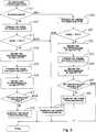
Schalterausfall-ErfassungsprozessSwitch failure detection process
Die CPU
Die CPU
Schalterausfall-Erfassungsprozess für den Ladestrom-Sperr-FET
Wenn sich die sekundäre Batterie
Die CPU
Wenn die Ein-Spannung VON1 niedriger als der erste Schwellwert TH1 ist (JA in S13), sendet die CPU
Die CPU
Die CPU
Die CPU
Wenn die Ein-Aus-Spannungsdifferenz ΔV1 kleiner als der zweite Schwellwert TH2 ist (JA in S17), führt die CPU
Wenn die Ein-Spannung VON1 höher als der erste Schwellwert TH1 ist (NEIN in S13), führt die CPU
Schalterausfall-Erfassungsprozess für den Entladestrom-Sperr-FET
Wenn sich die sekundäre Batterie
Die CPU
Wenn die Ein-Spannung VON2 niedriger als der dritte Schwellwert TH3 ist (JA in S21), sendet die CPU
Die CPU
Die CPU
Die CPU
Wenn die Ein-Aus-Spannungsdifferenz ΔD2 kleiner als der vierte Schwellwert TH4 ist (JA in S25), führt die CPU
Wenn die Ein-Spannung VON2 höher als der dritte Schwellwert TH3 ist (NEIN in S21), führt die CPU
In dieser Ausführungsform wird das Ausschaltproblem bestimmt, wenn die erfasste Ein-Aus-Spannungsdifferenz ΔV1 kleiner als der zweite Schwellwert TH2 ist und das Aus-Befehlssignal zu dem Ladestrom-Sperr-FET
Das Ausschaltproblem wird auch bestimmt, wenn die erfasste Ein-Aus-Spannungsdifferenz ΔV2 kleiner als der vierte Schwellwert TH4 ist und das Aus-Befehlssignal zu dem Entladestrom-Sperr-FET
Wenn die Ein-Aus-Spannungsdifferenzen ΔV1 und ΔV2 kleiner als die entsprechenden Schwellwerte TH2 und TH4 sind, wird das Ausschaltproblem bestimmt. Im Vergleich zu einer Konfiguration, in welcher das Ausschaltproblem bestimmt wird, wenn die Aus-Spannung VOFF1 oder VOFF2 kleiner als ein Schwellwert ist, neigt die Genauigkeit bei der Erfassung des Ausschaltproblems auch dann nicht zu einer Reduktion, wenn der Ein-Widerstand des FET
Wenn der FET
<Andere Ausführungsformen>Other Embodiments
Der Erfindungsumfang ist nicht auf die oben beschriebene Ausführungsform beschränkt. Die folgenden Ausführungsformen sind ebenfalls in dem Umfang der hier beschriebenen Techniken enthalten.The scope of the invention is not limited to the embodiment described above. The following embodiments are also included within the scope of the techniques described herein.
Die Steuereinrichtung
Die Schalter können bipolare Transistoren, Relais oder andere Typen von Schaltern sein, die keine parasitären Dioden enthalten. Die Gleichrichter können Dioden oder mit Dioden verbundene Transistoren sein. Ein Ausgang eines der mit Dioden verbundenen Transistoren ist mit einem Eingang eines anderen der mit Dioden verbundenen Transistoren verbunden. Die weiter oben beschriebene Ausführungsform kann den Schalterausfall-Erfassungsprozess jedoch auch unter Verwendung von bestehenden Komponenten ohne zusätzliche Komponenten durchführen.The switches may be bipolar transistors, relays, or other types of switches that do not contain parasitic diodes. The rectifiers may be diodes or diode-connected transistors. An output of one of the diodes-connected transistors is connected to an input of another of the diodes-connected transistors. However, the embodiment described above may also perform the switch failure detection process using existing components without additional components.
Die Steuereinrichtung
Die Steuereinrichtung kann auch konfiguriert sein, um den Schalterausfall-Erfassungsprozess für nur den Ladestrom-Sperr-FET
Die Eingang-Ausgang-Spannung kann die Aus-Spannung VOFF1 oder die Aus-Spannung VOFF2 sein.The input-output voltage may be the off-voltage VOFF1 or the off-voltage VOFF2.
ZITATE ENTHALTEN IN DER BESCHREIBUNG QUOTES INCLUDE IN THE DESCRIPTION
Diese Liste der vom Anmelder aufgeführten Dokumente wurde automatisiert erzeugt und ist ausschließlich zur besseren Information des Lesers aufgenommen. Die Liste ist nicht Bestandteil der deutschen Patent- bzw. Gebrauchsmusteranmeldung. Das DPMA übernimmt keinerlei Haftung für etwaige Fehler oder Auslassungen.This list of the documents listed by the applicant has been generated automatically and is included solely for the better information of the reader. The list is not part of the German patent or utility model application. The DPMA assumes no liability for any errors or omissions.
Zitierte PatentliteraturCited patent literature
- JP 2010-251104 A[0004]JP 2010-251104 A[0004]
Claims (12)
Translated fromGermanApplications Claiming Priority (2)
| Application Number | Priority Date | Filing Date | Title |
|---|---|---|---|
| JP2012045676AJP5910172B2 (en) | 2012-03-01 | 2012-03-01 | Switch failure diagnosis device, battery pack, switch failure diagnosis program, switch failure diagnosis method |
| JP2012-45676 | 2012-03-01 |
Publications (2)
| Publication Number | Publication Date |
|---|---|
| DE102013203545A1true DE102013203545A1 (en) | 2013-09-05 |
| DE102013203545B4 DE102013203545B4 (en) | 2021-08-05 |
Family
ID=48985234
Family Applications (2)
| Application Number | Title | Priority Date | Filing Date |
|---|---|---|---|
| DE102013203545.4AActiveDE102013203545B4 (en) | 2012-03-01 | 2013-03-01 | Switch failure detection apparatus and method for detecting failure of an electronic switch |
| DE202013012200.5UExpired - LifetimeDE202013012200U1 (en) | 2012-03-01 | 2013-03-01 | Switch failure detection device |
Family Applications After (1)
| Application Number | Title | Priority Date | Filing Date |
|---|---|---|---|
| DE202013012200.5UExpired - LifetimeDE202013012200U1 (en) | 2012-03-01 | 2013-03-01 | Switch failure detection device |
Country Status (5)
| Country | Link |
|---|---|
| US (4) | US9121907B2 (en) |
| JP (2) | JP5910172B2 (en) |
| KR (1) | KR101980848B1 (en) |
| CN (2) | CN103296715B (en) |
| DE (2) | DE102013203545B4 (en) |
Cited By (2)
| Publication number | Priority date | Publication date | Assignee | Title |
|---|---|---|---|---|
| DE102014210648A1 (en) | 2014-06-04 | 2015-12-17 | Robert Bosch Gmbh | battery system |
| DE112014004323B4 (en) | 2013-09-19 | 2021-07-22 | Kabushiki Kaisha Toyota Jidoshokki | System unit for battery control |
Families Citing this family (85)
| Publication number | Priority date | Publication date | Assignee | Title |
|---|---|---|---|---|
| JP5910172B2 (en)* | 2012-03-01 | 2016-04-27 | 株式会社Gsユアサ | Switch failure diagnosis device, battery pack, switch failure diagnosis program, switch failure diagnosis method |
| JP2015054009A (en)* | 2013-09-11 | 2015-03-23 | セイコーエプソン株式会社 | Control device |
| US9592744B2 (en) | 2013-12-06 | 2017-03-14 | SZ DJI Technology Co., Ltd | Battery and unmanned aerial vehicle with the battery |
| CN103701163B (en)* | 2013-12-06 | 2018-05-01 | 深圳市大疆创新科技有限公司 | Battery, aircraft with battery and battery control method |
| JP6418874B2 (en) | 2014-01-15 | 2018-11-07 | 株式会社マキタ | Battery pack |
| SG11201606222UA (en)* | 2014-01-28 | 2016-08-30 | Guang Dong Oppo Mobile Telecomm Corp Ltd | Power adapter, terminal, and method for processing impedance exception of charging loop |
| CN103852722B (en)* | 2014-03-17 | 2016-11-23 | 国家电网公司 | Circuit breaker internal mechanism folding identifier |
| US9748768B2 (en) | 2014-03-21 | 2017-08-29 | Lg Chem, Ltd. | Pre-charging and voltage supply system for a DC-AC inverter |
| US9413184B2 (en) | 2014-03-21 | 2016-08-09 | Lg Chem, Ltd. | Pre-charging and voltage supply system for a DC-AC inverter |
| US9537333B2 (en)* | 2014-04-22 | 2017-01-03 | Lg Chem, Ltd. | Voltage supply system and method for disabling operation of a DC-DC voltage converter |
| KR101678277B1 (en)* | 2014-10-06 | 2016-11-21 | 주식회사 엘지화학 | Apparatus and method for detecting degradation of switch |
| KR20160064734A (en)* | 2014-11-28 | 2016-06-08 | 삼성전자주식회사 | Method for charging control and an electronic device thereof |
| CN105717446B (en)* | 2014-12-05 | 2018-11-30 | 神讯电脑(昆山)有限公司 | RF switch test device |
| JP6729390B2 (en)* | 2014-12-24 | 2020-07-22 | 株式会社Gsユアサ | Power protection device, power supply device and switch failure diagnosis method |
| JP6709908B2 (en)* | 2015-04-03 | 2020-06-17 | パナソニックIpマネジメント株式会社 | Failure detection device |
| JP6406146B2 (en)* | 2015-07-21 | 2018-10-17 | 住友電気工業株式会社 | Power supply |
| EP3171473B1 (en)* | 2015-11-17 | 2021-04-21 | Siemens Aktiengesellschaft | Method and protection device for monitoring a power circuit breaker in an electrical energy supply network |
| CN105870990A (en)* | 2016-01-07 | 2016-08-17 | 乐视移动智能信息技术(北京)有限公司 | Rechargeable battery protection circuit and mobile terminal |
| JP6614443B2 (en)* | 2016-01-27 | 2019-12-04 | 株式会社Gsユアサ | Battery device, vehicle, battery management program, and battery device management method |
| JP6769046B2 (en)* | 2016-03-01 | 2020-10-14 | 株式会社Gsユアサ | Power storage element monitoring device, power storage element module, SOC estimation method |
| JP6339617B2 (en)* | 2016-03-28 | 2018-06-06 | 矢崎総業株式会社 | Power shut-off device |
| JP6689373B2 (en)* | 2016-05-16 | 2020-04-28 | 株式会社東芝 | Battery control device, abnormality detection method, and program |
| JP6765225B2 (en)* | 2016-06-09 | 2020-10-07 | ローム株式会社 | Switch status judgment device |
| JP6691665B2 (en)* | 2016-08-05 | 2020-05-13 | 株式会社Gsユアサ | Power storage device, power storage device control method, vehicle |
| JP6828296B2 (en)* | 2016-08-09 | 2021-02-10 | 株式会社Gsユアサ | Power storage device and charge control method for power storage device |
| CN106249138A (en)* | 2016-08-29 | 2016-12-21 | 杭州鸿雁智能科技有限公司 | The automatic checkout system of a kind of intelligent switch and detection method |
| CN106451767A (en)* | 2016-09-18 | 2017-02-22 | 国网河南伊川县供电公司 | On-line detection method and system for secondary power supply system of power substation |
| JP6885698B2 (en)* | 2016-09-30 | 2021-06-16 | シャープ株式会社 | Fault diagnostic equipment, methods, programs and electric mobiles |
| CN108051748A (en)* | 2016-10-20 | 2018-05-18 | 乐视生态汽车(浙江)有限公司 | Abort situation detection method, device, accumulator cell assembly and motor vehicle |
| KR101796395B1 (en)* | 2016-10-31 | 2017-11-10 | 엘에스오토모티브 주식회사 | Apparatus and method for detecting fault of converter |
| JP6665757B2 (en)* | 2016-11-08 | 2020-03-13 | 株式会社デンソー | Power control device and battery unit |
| KR102058198B1 (en) | 2016-12-12 | 2019-12-20 | 주식회사 엘지화학 | Apparatus for detecting relay fault of battery using parallel circuit for constant power suppy and method thereof |
| US10921374B2 (en)* | 2017-02-23 | 2021-02-16 | Gs Yuasa International Ltd. | Diagnosis device, energy storage apparatus, and diagnosis method |
| EA201992106A1 (en)* | 2017-03-06 | 2020-02-03 | Джапан Тобакко Инк. | BATTERY UNIT, INHALATOR FOR TASTE AROMATIC MATERIAL, METHOD FOR MANAGING THE BATTERY UNIT AND PROGRAM |
| JP6791796B2 (en)* | 2017-03-29 | 2020-11-25 | Fdk株式会社 | Charging device |
| US11189891B2 (en)* | 2017-07-03 | 2021-11-30 | Gs Yuasa Interational Ltd. | Energy storage apparatus, vehicle, and motorcycle |
| KR102362949B1 (en)* | 2017-08-28 | 2022-02-15 | 현대모비스 주식회사 | Power failure diagnosis apparatus of mdps sensor and method thereof |
| WO2019044068A1 (en)* | 2017-08-30 | 2019-03-07 | 矢崎総業株式会社 | Semiconductor relay and vehicle current detection device |
| JP2019068662A (en)* | 2017-10-03 | 2019-04-25 | 株式会社オートネットワーク技術研究所 | Power supply system |
| KR102256598B1 (en) | 2017-11-29 | 2021-05-26 | 주식회사 엘지에너지솔루션 | Battery back |
| CN108248390B (en)* | 2018-01-15 | 2020-05-01 | 浙江吉利汽车研究院有限公司 | High-voltage battery discharge circuit and control method thereof |
| JP7159565B2 (en)* | 2018-02-07 | 2022-10-25 | 株式会社オートネットワーク技術研究所 | Power supply control device, power supply control method and computer program |
| JP6770986B2 (en)* | 2018-03-06 | 2020-10-21 | 日本電産モビリティ株式会社 | Inductive load controller |
| JP6963358B2 (en)* | 2018-03-26 | 2021-11-10 | 株式会社エンビジョンAescジャパン | Power supply |
| JP7219104B2 (en)* | 2018-04-02 | 2023-02-07 | マレリ株式会社 | Diagnostic device and diagnostic method |
| JP7060435B2 (en) | 2018-04-19 | 2022-04-26 | Fdk株式会社 | Charger with failure detection function and failure detection method |
| KR102185036B1 (en) | 2018-04-30 | 2020-12-01 | 엘에스일렉트릭(주) | Circuit breaker control module |
| CN109116241A (en)* | 2018-06-28 | 2019-01-01 | 厦门美图移动科技有限公司 | A kind of battery testing method, mobile terminal and storage medium |
| KR102412313B1 (en)* | 2018-07-17 | 2022-06-22 | 주식회사 엘지에너지솔루션 | Apparatus and method for diagnosing switch |
| US10777998B2 (en) | 2018-08-02 | 2020-09-15 | GM Global Technology Operations LLC | Circuit for identifying the source of a power fault in a dual power source electrical system |
| KR102433848B1 (en)* | 2018-09-12 | 2022-08-17 | 주식회사 엘지에너지솔루션 | Apparatus and method for diagnosing switch |
| US11368032B2 (en) | 2018-09-30 | 2022-06-21 | Guangdong Oppo Mobile Telecommunications Corp., Ltd. | Test system and test method for charging device |
| CN109319234B (en)* | 2018-10-24 | 2021-09-17 | 河南中烟工业有限责任公司 | Packagine machine emergency protection switch tripping fault diagnostic system |
| KR102690979B1 (en)* | 2018-11-05 | 2024-07-31 | 주식회사 엘지에너지솔루션 | Apparatus and method for diagnosing a power switch |
| CN113167204B (en)* | 2018-12-11 | 2022-07-15 | 株式会社自动网络技术研究所 | Control device and failure determination method |
| US11251626B2 (en)* | 2019-01-15 | 2022-02-15 | Lithium Power Inc. | System for lead-acid battery replacement |
| EP3767316B1 (en)* | 2019-07-19 | 2022-03-30 | Yazaki Corporation | Switch failure detection device |
| WO2021014558A1 (en)* | 2019-07-23 | 2021-01-28 | 三菱電機株式会社 | Input diagnosis device and input diagnosis method |
| DE102019127733B4 (en)* | 2019-10-15 | 2021-06-02 | Leoni Bordnetz-Systeme Gmbh | System and method for the detection of non-switching semiconductor switches |
| KR102851360B1 (en) | 2019-10-29 | 2025-08-26 | 주식회사 엘지에너지솔루션 | Error detecting method of charging switch unit and battery system using the same |
| CN113874741B (en)* | 2019-11-13 | 2024-03-15 | 株式会社Lg新能源 | Apparatus and method for diagnosing failure, battery management system and electric drive mechanism |
| GB2590456B (en)* | 2019-12-19 | 2022-04-13 | Dyson Technology Ltd | Battery pack with failure detection system |
| KR20210087813A (en) | 2020-01-03 | 2021-07-13 | 주식회사 엘지에너지솔루션 | Apparatus for controlling relay |
| JP7014237B2 (en)* | 2020-02-17 | 2022-02-01 | トヨタ自動車株式会社 | Battery controls, methods, programs, and vehicles |
| JP7622349B2 (en)* | 2020-03-27 | 2025-01-28 | 株式会社Gsユアサ | Power storage device |
| CN111551845B (en)* | 2020-05-27 | 2022-04-26 | 中创新航科技股份有限公司 | Switch detection circuit and detection method |
| KR102839452B1 (en)* | 2020-09-29 | 2025-07-25 | 주식회사 엘지에너지솔루션 | Relay fault diagnosis method and battery system using the same |
| KR20220114976A (en)* | 2021-02-09 | 2022-08-17 | 주식회사 엘지에너지솔루션 | Apparatus and method for power supply management |
| US20240106249A1 (en) | 2021-02-25 | 2024-03-28 | Panasonic Energy Co., Ltd. | Battery pack failure diagnostic method and battery pack |
| WO2022239511A1 (en)* | 2021-05-10 | 2022-11-17 | 日本たばこ産業株式会社 | Power supply unit for aerosol generation device |
| DE102021204766A1 (en) | 2021-05-11 | 2022-11-17 | Robert Bosch Gesellschaft mit beschränkter Haftung | Semiconductor switch assembly with monitoring function, energy system and vehicle |
| US11699998B2 (en)* | 2021-08-17 | 2023-07-11 | Allison Transmission, Inc. | Switch assembly with feedback signal for fault detection |
| CN113555848B (en)* | 2021-08-18 | 2025-07-29 | 珠海冠宇动力电池有限公司 | Battery system and switching device diagnosis method in battery system |
| KR20230095314A (en)* | 2021-12-22 | 2023-06-29 | 주식회사 엘지에너지솔루션 | Apparatus and method for diagnosing damage of switch on battery protection circuit and battery management apparatus having the same |
| CN114252752B (en)* | 2021-12-22 | 2022-12-16 | 清华大学 | Fault Diagnosis Method of Power Transistor in Fully Controlled Bridge Topology Circuit |
| CN114336855B (en)* | 2021-12-29 | 2023-11-28 | 蜂巢能源科技(无锡)有限公司 | Control method and device of battery pack system and energy storage system |
| CN114217220B (en)* | 2022-02-23 | 2022-05-17 | 深圳市德兰明海科技有限公司 | Switch detection circuit and method and switch detector |
| JPWO2023176228A1 (en) | 2022-03-18 | 2023-09-21 | ||
| CN114814510A (en)* | 2022-03-19 | 2022-07-29 | 立讯精密工业(芜湖)有限公司 | MOSFET detection circuit and fault diagnosis method |
| EP4293369A1 (en)* | 2022-06-16 | 2023-12-20 | Panasonic Industrial Devices Europe GmbH | Safety switch diagnosis and fault detection |
| CN115629322A (en)* | 2022-09-08 | 2023-01-20 | 五羊—本田摩托(广州)有限公司 | Double-battery-pack power-on fault detection method and double-battery-pack charging and discharging system |
| JP2024110086A (en)* | 2023-02-02 | 2024-08-15 | 株式会社Gsユアサ | POWER STORAGE DEVICE, SWITCH FAILURE DIAGNOSIS METHOD, AND SWITCH FAILURE DIAGNOSIS PROGRAM |
| WO2025017778A1 (en)* | 2023-07-14 | 2025-01-23 | 日産自動車株式会社 | Semiconductor switch control device, control system, and semiconductor switch control method |
| CN116699425B (en)* | 2023-07-28 | 2024-04-12 | 荣耀终端有限公司 | Battery detection method, electronic device, storage medium and program product |
| JP2025122386A (en)* | 2024-02-08 | 2025-08-21 | 株式会社Gsユアサ | Fault diagnosis method for power storage device and circuit breaker |
Citations (1)
| Publication number | Priority date | Publication date | Assignee | Title |
|---|---|---|---|---|
| JP2010251104A (en) | 2009-04-15 | 2010-11-04 | Sanyo Electric Co Ltd | Battery pack |
Family Cites Families (51)
| Publication number | Priority date | Publication date | Assignee | Title |
|---|---|---|---|---|
| GB1404192A (en)* | 1972-06-07 | 1975-08-28 | Electro Mechanical Constructio | Switching apparatus |
| JPS6154880A (en)* | 1984-08-24 | 1986-03-19 | Toshiba Corp | power supply |
| US4705962A (en)* | 1986-10-14 | 1987-11-10 | Rockwell International Corporation | Solid state dc rate of rise controlled switch |
| US5264777A (en)* | 1991-07-24 | 1993-11-23 | Ample Power Company | System for isolating commonly charged batteries |
| US5258244A (en)* | 1991-12-09 | 1993-11-02 | Hughes Aircraft Company | Reversible automatic cell bypass circuit |
| US5530336A (en)* | 1992-09-17 | 1996-06-25 | Sony Corporation | Battery protection circuit |
| US5825155A (en)* | 1993-08-09 | 1998-10-20 | Kabushiki Kaisha Toshiba | Battery set structure and charge/ discharge control apparatus for lithium-ion battery |
| US6060864A (en)* | 1994-08-08 | 2000-05-09 | Kabushiki Kaisha Toshiba | Battery set structure and charge/discharge control apparatus for lithium-ion battery |
| JP3584502B2 (en)* | 1994-10-07 | 2004-11-04 | ソニー株式会社 | Charge control device |
| FR2731110B1 (en)* | 1995-02-23 | 1997-05-16 | Texas Instruments France | RECHARGEABLE BATTERY PROTECTION DEVICE AND MOSFET TRANSISTOR EQUIPPED WITH THIS DEVICE |
| JPH0917455A (en) | 1995-06-28 | 1997-01-17 | Sony Corp | Battery pack control device and method |
| JP3429927B2 (en)* | 1995-10-16 | 2003-07-28 | 三菱電機株式会社 | Normalization circuit device of floating point arithmetic unit |
| JP3713770B2 (en)* | 1995-11-09 | 2005-11-09 | ソニー株式会社 | Secondary battery pack |
| JP3597617B2 (en)* | 1995-12-27 | 2004-12-08 | 株式会社日立超エル・エス・アイ・システムズ | Secondary battery protection circuit |
| US5672952A (en)* | 1996-07-01 | 1997-09-30 | Analog Devices, Inc. | Controller for battery charger with reduced reverse leakage current |
| TW468295B (en)* | 1999-04-15 | 2001-12-11 | Seiko Instr Inc | Charge/discharge controlling semiconductor device |
| WO2001059905A1 (en)* | 2000-02-07 | 2001-08-16 | Fujitsu Limited | Charger and power unit of portable terminal |
| US6917124B2 (en)* | 2000-10-27 | 2005-07-12 | Liebert Corporation | Uninterruptible power supply |
| KR100903405B1 (en)* | 2002-12-11 | 2009-06-18 | 가부시키가이샤 아드반테스트 | Voltage-impressed current measuring apparatus and current buffers with switches used therefor |
| US7737658B2 (en)* | 2003-10-27 | 2010-06-15 | Sony Corporation | Battery packs having a charging mode and a discharging mode |
| US7436151B2 (en)* | 2004-12-23 | 2008-10-14 | Dell Products L.P. | Systems and methods for detecting charge switching element failure in a battery system |
| US7952330B2 (en)* | 2005-04-20 | 2011-05-31 | Panasonic Corporation | Secondary battery protection circuit, battery pack and thermosensitive protection switch device |
| US7642750B2 (en) | 2005-10-04 | 2010-01-05 | O2Micro International Limited | Battery charge/discharge control circuit |
| CN100405698C (en)* | 2005-10-04 | 2008-07-23 | 美国凹凸微系有限公司 | Battery charge/discharge control circuit |
| EP1821386A2 (en)* | 2006-02-17 | 2007-08-22 | Power Systems Co., Ltd. | Charging apparatus for capacitor storage type power source and discharging apparatus for capacitor storage type power source |
| JP2008005593A (en)* | 2006-06-21 | 2008-01-10 | Sony Corp | Battery pack, electronic apparatus, and control method |
| TWI317184B (en)* | 2006-07-17 | 2009-11-11 | Compal Electronics Inc | A hybrid battery module with a voltage balance unit and its charging and discharging method |
| JP4898343B2 (en)* | 2006-08-09 | 2012-03-14 | パナソニック株式会社 | Power supply |
| JP2008092768A (en)* | 2006-10-05 | 2008-04-17 | Nippon Telegr & Teleph Corp <Ntt> | Discharger, discharge control method, discharge control program, and program recording medium |
| JP4785708B2 (en)* | 2006-11-09 | 2011-10-05 | 三洋電機株式会社 | Pack battery control method |
| US7872447B2 (en)* | 2006-12-25 | 2011-01-18 | Panasonic Corporation | Electrical storage apparatus for use in auxiliary power supply supplying electric power from electric storage device upon voltage drop of main power supply |
| US8493033B2 (en)* | 2007-01-30 | 2013-07-23 | Won-Door Corporation | Method and apparatus for battery-backed power supply and battery charging |
| US7804194B2 (en)* | 2007-07-18 | 2010-09-28 | Odo Innovations Ltd. | Device, system and method for charger switch adaptor |
| JP4728303B2 (en) | 2007-08-31 | 2011-07-20 | パナソニック株式会社 | Charging circuit, battery pack including the same, and charging system |
| JP5087779B2 (en)* | 2007-09-11 | 2012-12-05 | ソフトバンクモバイル株式会社 | Communication module, program, and communication terminal |
| US7602623B2 (en)* | 2007-12-28 | 2009-10-13 | International Business Machines Corporation | Apparatus, system, and method for a low cost self-healing power supply |
| JP5061935B2 (en)* | 2008-02-12 | 2012-10-31 | ミツミ電機株式会社 | Battery pack |
| JP5049162B2 (en) | 2008-02-18 | 2012-10-17 | パナソニック株式会社 | Fault diagnosis circuit and battery pack provided with the same |
| JP5098912B2 (en)* | 2008-07-11 | 2012-12-12 | ソニー株式会社 | Battery pack and charge control system |
| JP2010140785A (en)* | 2008-12-12 | 2010-06-24 | Panasonic Corp | Fault diagnosis circuit and battery pack |
| JP2010259274A (en)* | 2009-04-28 | 2010-11-11 | Toyota Motor Corp | Power storage device charging pack |
| US8101122B2 (en) | 2009-05-06 | 2012-01-24 | General Electric Company | NiCrMoCb alloy with improved mechanical properties |
| US8503201B2 (en)* | 2009-12-03 | 2013-08-06 | Schneider Electric It Corporation | Transient clamping circuitry for voltage converter |
| CN102122813B (en)* | 2010-01-11 | 2015-11-25 | 日隆电子股份有限公司 | The switch embedded integrated circuit of protection battery and method |
| US9425783B2 (en)* | 2010-03-15 | 2016-08-23 | Tigo Energy, Inc. | Systems and methods to provide enhanced diode bypass paths |
| JP2011229319A (en)* | 2010-04-21 | 2011-11-10 | Makita Corp | Electric tool battery pack |
| US8865328B2 (en)* | 2010-06-09 | 2014-10-21 | Samsung Sdi Co., Ltd. | Battery protecting circuit, method of controlling the same, and battery pack |
| US20120268969A1 (en)* | 2011-04-20 | 2012-10-25 | Cuks, Llc | Dc-ac inverter with high frequency isolation transformer |
| CN103066633B (en)* | 2011-10-18 | 2015-11-18 | 丁景信 | Power management system |
| JP5910172B2 (en)* | 2012-03-01 | 2016-04-27 | 株式会社Gsユアサ | Switch failure diagnosis device, battery pack, switch failure diagnosis program, switch failure diagnosis method |
| CN104967182A (en)* | 2015-07-20 | 2015-10-07 | 苏州衡久电池科技有限公司 | Fast balanced-type protection management method for two-wheeler lithium battery |
- 2012
- 2012-03-01JPJP2012045676Apatent/JP5910172B2/enactiveActive
- 2013
- 2013-02-26CNCN201310059853.8Apatent/CN103296715B/enactiveActive
- 2013-02-26CNCN201710511195.XApatent/CN107240944B/enactiveActive
- 2013-02-28KRKR1020130022173Apatent/KR101980848B1/enactiveActive
- 2013-02-28USUS13/781,558patent/US9121907B2/ennot_activeExpired - Fee Related
- 2013-03-01DEDE102013203545.4Apatent/DE102013203545B4/enactiveActive
- 2013-03-01DEDE202013012200.5Upatent/DE202013012200U1/ennot_activeExpired - Lifetime
- 2015
- 2015-07-10USUS14/796,659patent/US9383412B2/enactiveActive
- 2016
- 2016-03-28JPJP2016063469Apatent/JP6327278B2/enactiveActive
- 2016-06-10USUS15/178,980patent/US9500708B2/enactiveActive
- 2016-10-21USUS15/299,915patent/US9599674B2/enactiveActive
Patent Citations (1)
| Publication number | Priority date | Publication date | Assignee | Title |
|---|---|---|---|---|
| JP2010251104A (en) | 2009-04-15 | 2010-11-04 | Sanyo Electric Co Ltd | Battery pack |
Cited By (3)
| Publication number | Priority date | Publication date | Assignee | Title |
|---|---|---|---|---|
| DE112014004323B4 (en) | 2013-09-19 | 2021-07-22 | Kabushiki Kaisha Toyota Jidoshokki | System unit for battery control |
| DE102014210648A1 (en) | 2014-06-04 | 2015-12-17 | Robert Bosch Gmbh | battery system |
| CN105322601A (en)* | 2014-06-04 | 2016-02-10 | 罗伯特·博世有限公司 | Battery system |
Also Published As
| Publication number | Publication date |
|---|---|
| US20170040809A1 (en) | 2017-02-09 |
| JP2016118571A (en) | 2016-06-30 |
| CN103296715B (en) | 2017-07-04 |
| US9599674B2 (en) | 2017-03-21 |
| US20150316617A1 (en) | 2015-11-05 |
| KR101980848B1 (en) | 2019-05-21 |
| US20130229186A1 (en) | 2013-09-05 |
| DE202013012200U1 (en) | 2015-09-28 |
| JP6327278B2 (en) | 2018-05-23 |
| DE102013203545B4 (en) | 2021-08-05 |
| US9500708B2 (en) | 2016-11-22 |
| KR20130100740A (en) | 2013-09-11 |
| US20160282415A1 (en) | 2016-09-29 |
| CN107240944B (en) | 2019-08-20 |
| CN103296715A (en) | 2013-09-11 |
| US9121907B2 (en) | 2015-09-01 |
| CN107240944A (en) | 2017-10-10 |
| JP5910172B2 (en) | 2016-04-27 |
| JP2013181822A (en) | 2013-09-12 |
| US9383412B2 (en) | 2016-07-05 |
Similar Documents
| Publication | Publication Date | Title |
|---|---|---|
| DE102013203545B4 (en) | Switch failure detection apparatus and method for detecting failure of an electronic switch | |
| DE4138943C1 (en) | ||
| DE10035959B4 (en) | Method for discharging a plurality of rechargeable batteries and battery assembly | |
| DE69839115T2 (en) | BATTERY PROTECTION SYSTEM | |
| DE112013006920B4 (en) | Failure detection device for voltage sensor | |
| DE112013007438B4 (en) | Electrical storage device for a vehicle | |
| DE102019108399A1 (en) | Redundant energy supply system | |
| DE102017201171A1 (en) | BATTERY DEVICE, VEHICLE, BATTERY MANAGEMENT PROGRAM AND ADMINISTRATIVE PROCESS FOR A BATTERY DEVICE | |
| DE102018202680A1 (en) | Diagnostic device, energy storage device and diagnostic method | |
| DE102019112271B4 (en) | CIRCUIT FOR IDENTIFYING THE SOURCE OF A POWER FAULT IN AN ELECTRICAL SYSTEM WITH TWO POWER SOURCES | |
| DE102017213380A1 (en) | An energy storage device for an engine start, method for controlling it and vehicle | |
| DE102012109430A1 (en) | Automatic battery discharge process after a crash | |
| DE102017222965A1 (en) | Control device, control system, electrical storage device and computer readable medium | |
| DE4225746A1 (en) | Circuit device | |
| DE102012201381A1 (en) | Method for charge compensation in a memory arrangement and charge equalization circuit | |
| DE112012007192B4 (en) | electricity storage system | |
| DE102017213136A1 (en) | An energy storage device, vehicle, control method for detecting an internal short circuit for an energy storage device and charging control method for an energy storage device | |
| DE112018006195T5 (en) | CHARGING CONTROL DEVICE, ENERGY STORAGE DEVICE, AND CHARGING METHOD | |
| DE102020208401A1 (en) | Method for safeguarding, in particular, safety-relevant consumers in a motor vehicle | |
| DE112018002844T5 (en) | PROTECTIVE DEVICE FOR ENERGY STORAGE DEVICE | |
| DE112019004988T5 (en) | ELECTRIC STORAGE SYSTEM | |
| DE102018222554A1 (en) | Device and method for the direction-dependent operation of an electrochemical energy store | |
| DE102011005425A1 (en) | A storage device for storing electrical energy and method for operating a storage device | |
| DE112018005187T5 (en) | Management device, energy storage apparatus, cause analysis method, motor-driven vehicle and electric vehicle | |
| DE102023107237A1 (en) | ADHESIVE DIAGNOSTIC DEVICE AND METHOD FOR ADHESIVE DIAGNOSIS |
Legal Events
| Date | Code | Title | Description |
|---|---|---|---|
| R138 | Derivation of utility model | Ref document number:202013012200 Country of ref document:DE | |
| R012 | Request for examination validly filed | ||
| R016 | Response to examination communication | ||
| R018 | Grant decision by examination section/examining division | ||
| R020 | Patent grant now final |