DE102013200137A1 - Microlithographic projection exposure system operating method for manufacturing e.g. LCDs, involves illuminating regions of plane in rotational positions of lambda/two-plate, and adjusting mirror arrangement with light pulses - Google Patents
Microlithographic projection exposure system operating method for manufacturing e.g. LCDs, involves illuminating regions of plane in rotational positions of lambda/two-plate, and adjusting mirror arrangement with light pulsesDownload PDFInfo
- Publication number
- DE102013200137A1 DE102013200137A1DE201310200137DE102013200137ADE102013200137A1DE 102013200137 A1DE102013200137 A1DE 102013200137A1DE 201310200137DE201310200137DE 201310200137DE 102013200137 ADE102013200137 ADE 102013200137ADE 102013200137 A1DE102013200137 A1DE 102013200137A1
- Authority
- DE
- Germany
- Prior art keywords
- lambda
- plate
- mirror arrangement
- area
- pupil plane
- Prior art date
- Legal status (The legal status is an assumption and is not a legal conclusion. Google has not performed a legal analysis and makes no representation as to the accuracy of the status listed.)
- Withdrawn
Links
- 238000004519manufacturing processMethods0.000titledescription2
- 238000011017operating methodMethods0.000title1
- 230000010287polarizationEffects0.000claimsabstractdescription51
- 238000009826distributionMethods0.000claimsabstractdescription38
- 238000005286illuminationMethods0.000claimsabstractdescription29
- 210000001747pupilAnatomy0.000claimsabstractdescription23
- 238000000034methodMethods0.000claimsabstractdescription20
- 230000001360synchronised effectEffects0.000claimsabstractdescription7
- 230000002123temporal effectEffects0.000claimsabstractdescription4
- 230000003287optical effectEffects0.000claimsdescription20
- 238000006073displacement reactionMethods0.000abstract1
- 230000005684electric fieldEffects0.000description6
- 239000013598vectorSubstances0.000description6
- 230000010355oscillationEffects0.000description3
- 239000000758substrateSubstances0.000description3
- 230000007704transitionEffects0.000description3
- 238000003384imaging methodMethods0.000description2
- BUHVIAUBTBOHAG-FOYDDCNASA-N(2r,3r,4s,5r)-2-[6-[[2-(3,5-dimethoxyphenyl)-2-(2-methylphenyl)ethyl]amino]purin-9-yl]-5-(hydroxymethyl)oxolane-3,4-diolChemical compoundCOC1=CC(OC)=CC(C(CNC=2C=3N=CN(C=3N=CN=2)[C@H]2[C@@H]([C@H](O)[C@@H](CO)O2)O)C=2C(=CC=CC=2)C)=C1BUHVIAUBTBOHAG-FOYDDCNASA-N0.000description1
- XUIMIQQOPSSXEZ-UHFFFAOYSA-NSiliconChemical compound[Si]XUIMIQQOPSSXEZ-UHFFFAOYSA-N0.000description1
- 238000013459approachMethods0.000description1
- 230000000712assemblyEffects0.000description1
- 238000000429assemblyMethods0.000description1
- 239000011248coating agentSubstances0.000description1
- 238000000576coating methodMethods0.000description1
- 230000001419dependent effectEffects0.000description1
- 238000007654immersionMethods0.000description1
- 230000000873masking effectEffects0.000description1
- 238000001393microlithographyMethods0.000description1
- 239000000203mixtureSubstances0.000description1
- 229920002120photoresistant polymerPolymers0.000description1
- 238000007493shaping processMethods0.000description1
- 229910052710siliconInorganic materials0.000description1
- 239000010703siliconSubstances0.000description1
Images


Classifications
- G—PHYSICS
- G03—PHOTOGRAPHY; CINEMATOGRAPHY; ANALOGOUS TECHNIQUES USING WAVES OTHER THAN OPTICAL WAVES; ELECTROGRAPHY; HOLOGRAPHY
- G03F—PHOTOMECHANICAL PRODUCTION OF TEXTURED OR PATTERNED SURFACES, e.g. FOR PRINTING, FOR PROCESSING OF SEMICONDUCTOR DEVICES; MATERIALS THEREFOR; ORIGINALS THEREFOR; APPARATUS SPECIALLY ADAPTED THEREFOR
- G03F7/00—Photomechanical, e.g. photolithographic, production of textured or patterned surfaces, e.g. printing surfaces; Materials therefor, e.g. comprising photoresists; Apparatus specially adapted therefor
- G03F7/70—Microphotolithographic exposure; Apparatus therefor
- G03F7/70483—Information management; Active and passive control; Testing; Wafer monitoring, e.g. pattern monitoring
- G03F7/7055—Exposure light control in all parts of the microlithographic apparatus, e.g. pulse length control or light interruption
- G03F7/70566—Polarisation control
- G—PHYSICS
- G03—PHOTOGRAPHY; CINEMATOGRAPHY; ANALOGOUS TECHNIQUES USING WAVES OTHER THAN OPTICAL WAVES; ELECTROGRAPHY; HOLOGRAPHY
- G03F—PHOTOMECHANICAL PRODUCTION OF TEXTURED OR PATTERNED SURFACES, e.g. FOR PRINTING, FOR PROCESSING OF SEMICONDUCTOR DEVICES; MATERIALS THEREFOR; ORIGINALS THEREFOR; APPARATUS SPECIALLY ADAPTED THEREFOR
- G03F7/00—Photomechanical, e.g. photolithographic, production of textured or patterned surfaces, e.g. printing surfaces; Materials therefor, e.g. comprising photoresists; Apparatus specially adapted therefor
- G03F7/70—Microphotolithographic exposure; Apparatus therefor
- G03F7/70058—Mask illumination systems
- G03F7/70091—Illumination settings, i.e. intensity distribution in the pupil plane or angular distribution in the field plane; On-axis or off-axis settings, e.g. annular, dipole or quadrupole settings; Partial coherence control, i.e. sigma or numerical aperture [NA]
- G03F7/70116—Off-axis setting using a programmable means, e.g. liquid crystal display [LCD], digital micromirror device [DMD] or pupil facets
Landscapes
- Physics & Mathematics (AREA)
- General Physics & Mathematics (AREA)
- Exposure And Positioning Against Photoresist Photosensitive Materials (AREA)
Abstract
Description
Translated fromGermanDie Erfindung betrifft ein Verfahren zum Betreiben einer mikrolithographischen Projektionsbelichtungsanlage.The invention relates to a method for operating a microlithographic projection exposure apparatus.
Mikrolithographische Projektionsbelichtungsanlagen werden zur Herstellung mikrostrukturierter Bauelemente, wie beispielsweise integrierter Schaltkreise oder LCD's, angewendet. Eine solche Projektionsbelichtungsanlage weist eine Beleuchtungseinrichtung und ein Projektionsobjektiv auf. Im Mikrolithographieprozess wird das Bild einer mit Hilfe der Beleuchtungseinrichtung beleuchteten Maske (= Retikel) mittels des Projektionsobjektivs auf ein mit einer lichtempfindlichen Schicht (Photoresist) beschichtetes und in der Bildebene des Projektionsobjektivs angeordnetes Substrat (z. B. ein Siliziumwafer) projiziert, um die Maskenstruktur auf die lichtempfindliche Beschichtung des Substrats zu übertragen.Microlithographic projection exposure equipment is used to fabricate microstructured devices such as integrated circuits or LCDs. Such a projection exposure apparatus has an illumination device and a projection objective. In the microlithography process, the image of a mask (= reticle) illuminated with the aid of the illumination device is projected onto a substrate (eg a silicon wafer) coated with a photosensitive layer (photoresist) and arranged in the image plane of the projection objective in order to form the mask structure transferred to the photosensitive coating of the substrate.
Im Betrieb einer mikrolithographischen Projektionsbelichtungsanlage besteht der Bedarf, definierte Beleuchtungssettings, d. h. Intensitätsverteilungen in einer Pupillenebene der Beleuchtungseinrichtung, gezielt einzustellen. Hierzu ist außer der Verwendung diffraktiver optischer Elemente (sogenannter DOE's) auch der Einsatz von Spiegelanordnungen, z. B. aus
Es sind ferner verschiedene Ansätze bekannt, in der Beleuchtungseinrichtung zur Optimierung des Abbildungskontrastes gezielt bestimmte Polarisationsverteilungen in der Pupillenebene und/oder im Retikel einzustellen.Furthermore, various approaches are known for selectively setting specific polarization distributions in the pupil plane and / or in the reticle in the illumination device in order to optimize the imaging contrast.
Sowohl in der Beleuchtungseinrichtung als auch im Projektionsobjektiv ist es bekannt, für eine kontrastreiche Abbildung insbesondere eine tangentiale Polarisationsverteilung einzustellen. Unter „tangentialer Polarisation” (oder „TE-Polarisation”) wird eine Polarisationsverteilung verstanden, bei der die Schwingungsebenen der elektrischen Feldstärkevektoren der einzelnen linear polarisierten Lichtstrahlen annähernd senkrecht zum auf die optische Systemachse gerichteten Radius orientiert sind. Hingegen wird unter „radialer Polarisation” (oder „TM-Polarisation”) eine Polarisationsverteilung verstanden, bei der die Schwingungsebenen der elektrischen Feldstärkevektoren der einzelnen linear polarisierten Lichtstrahlen annähernd radial zur optischen Systemachse orientiert sind. Entsprechend wird unter einer quasi-tangentialen bzw. einer quasi-radialen Polarisationsverteilung eine Polarisationsverteilung verstanden, bei der die vorstehenden Kriterien zumindest näherungsweise erfüllt sind.Both in the illumination device and in the projection objective, it is known to set, in particular, a tangential polarization distribution for a high-contrast imaging. "Tangential polarization" (or "TE polarization") is understood to mean a polarization distribution in which the oscillation planes of the electric field strength vectors of the individual linearly polarized light beams are oriented approximately perpendicular to the radius directed onto the optical system axis. By contrast, "radial polarization" (or "TM polarization") is understood to mean a polarization distribution in which the oscillation planes of the electric field strength vectors of the individual linearly polarized light beams are oriented approximately radially to the optical system axis. Accordingly, a quasi-tangential or a quasi-radial polarization distribution is understood as meaning a polarization distribution in which the above criteria are at least approximately fulfilled.
Zum Stand der Technik wird beispielsweise auf
Es ist eine Aufgabe der vorliegenden Erfindung, ein Verfahren zum Betreiben einer mikrolithographischen Projektionsbelichtungsanlage bereitzustellen, welches in vergleichsweise einfacher Weise eine flexible Variation der in der Projektionsbelichtungsanlage eingestellten Polarisationsverteilung ermöglicht.It is an object of the present invention to provide a method for operating a microlithographic projection exposure apparatus, which allows in a comparatively simple manner a flexible variation of the polarization distribution set in the projection exposure apparatus.
Diese Aufgabe wird gemäß den Merkmalen des unabhängigen Patentanspruchs 1 gelöst.This object is achieved according to the features of independent claim 1.
Ein erfindungsgemäßes Verfahren zum Betreiben einer mikrolithographischen Projektionsbelichtungsanlage mit einer Beleuchtungseinrichtung und einem Projektionsobjektiv, wobei die Beleuchtungseinrichtung eine optische Systemachse, eine Pupillenebene, eine um die optische Systemachse drehbare Lambda/2-Platte sowie eine Spiegelanordnung mit einer Mehrzahl von unabhängig voneinander verstellbaren Spiegelelementen aufweist, weist folgende Schritte auf:
- – Beleuchten eines ersten Bereichs der Pupillenebene in einer ersten Drehstellung der Lambda/2-Platte und einer ersten Einstellung der Spiegelanordnung mit wenigstens einem ersten Lichtpuls; und
- – Beleuchten eines zweiten Bereichs der Pupillenebene in einer zweiten Drehstellung der Lambda/2-Platte und einer zweiten Einstellung der Spiegelanordnung mit wenigstens einem zweiten Lichtpuls, wobei der zweite Bereich von dem ersten Bereich verschieden ist.
- Illuminating a first region of the pupil plane in a first rotational position of the lambda / 2 plate and a first adjustment of the mirror device with at least one first light pulse; and
- Illuminating a second region of the pupil plane in a second rotational position of the lambda / 2 plate and a second adjustment of the mirror arrangement with at least one second light pulse, wherein the second region is different from the first region.
Der Erfindung liegt insbesondere das Konzept zugrunde, in einer Beleuchtungseinrichtung, welche sowohl eine drehbare Lambda/2-Platte als auch eine Spiegelanordnung mit unabhängig voneinander verstellbaren Spiegelelementen aufweist, die Einstellung eines gewünschten polarisierten Beleuchtungssettings (d. h. einer gewünschten Intensitäts- und Polarisationsverteilung in der Pupillenebene) dadurch zu realisieren, dass die betreffende Intensitäts- und Polarisationsverteilung über eine Mehrzahl von Beleuchtungsschritten zusammengesetzt wird, welche sich hinsichtlich der jeweils gerade gewählten Kombination aus Drehstellung der Lambda/2-Platte und Einstellung der Spiegelelemente der Spiegelanordnung voneinander unterscheiden.The invention is based in particular on the concept of setting a desired polarized illumination setting (ie a desired intensity and polarization distribution in the pupil plane) in an illumination device which has both a rotatable lambda / 2 plate and a mirror arrangement with mirror elements which can be adjusted independently of one another. to realize that the respective intensity and polarization distribution over a plurality of lighting steps is composed, which differ from each other with respect to the currently selected combination of rotational position of the lambda / 2 plate and adjustment of the mirror elements of the mirror assembly.
Dabei kann jeder einzelne dieser Beleuchtungsschritte entweder einen einzigen Lichtpuls (insbesondere Laserspot) oder auch eine Mehrzahl von zeitlich aufeinanderfolgenden Lichtpulsen bzw. Laserspots umfassen. Dadurch, dass zwischen den betreffenden Beleuchtungsschritten die Drehstellung der Lambda/2-Platte sowie auch die Einstellung der Spiegelanordnung (hinsichtlich der jeweils aktuellen Verstellung ihrer Spiegelelemente) unabhängig voneinander geändert werden können, ermöglicht die Erfindung es hierbei, Intensitäts- und Polarisationsverteilung unabhängig voneinander einzustellen, wobei sich die in Summe über die einzelnen Beleuchtungsschritte resultierende Intensitätsverteilung allein über die jeweiligen Einstellungen der Spiegelanordnung, die Polarisationsverteilung hingegen über die jeweiligen Kombinationen aus Drehstellung der Lambda/2-Platte einerseits mit Einstellung der Spiegelanordnung andererseits bestimmt wird.Each of these lighting steps can either be a single light pulse (in particular Laserspot) or a plurality of comprise temporally successive light pulses or laser spots. Because the rotational position of the lambda / 2 plate as well as the adjustment of the mirror arrangement (with respect to the respective current adjustment of its mirror elements) can be changed independently of one another, the invention makes it possible to set the intensity and polarization distribution independently of one another. whereby the intensity distribution resulting in total over the individual illumination steps is determined solely by the respective settings of the mirror arrangement, whereas the polarization distribution is determined via the respective combinations of rotational position of the lambda / 2 plate on the one hand with adjustment of the mirror arrangement on the other.
Im Ergebnis kann so in flexibler Weise und unter geringem konstruktivem Aufwand (insbesondere ohne aufwendig zu fertigende polarisationsbeeinflussende optische Elemente, sondern lediglich unter Bereitstellung einer geeigneten Drehmechanik zur Drehung der Lambda/2-Platte) eine flexible Einstellung gewünschter polarisierter Beleuchtungssettings erzielt werden, wobei es sich lediglich beispielhaft (und ohne dass die Erfindung hierauf beschränkt wäre) bei der letztlich (d. h. in Summe) eingestellten Intensitätsverteilung beispielsweise um ein annulares Beleuchtungssetting, ein Dipol- oder Quadrupol-Beleuchtungssetting oder auch um ein Freiform-Beleuchtungssetting mit beliebiger Anordnung und Geometrie von in der Pupillenebene erzeugten beleuchteten Bereiche bzw. Beleuchtungspole handeln kann. Infolge der Einstellbarkeit von Intensitätsverteilung und Polarisationsverteilung unabhängig voneinander kann ferner die betreffende, in Summe erzeugte Intensitätsverteilung mit einer beliebigen gewünschten Polarisationsverteilung, insbesondere etwa einer zumindest näherungsweise tangentialen, radialen oder gemischt tangential-radialen Polarisationsverteilung kombiniert werden.As a result, a flexible adjustment of desired polarized illumination settings can be achieved in a flexible manner and with little constructional outlay (in particular without polarization-influencing optical elements which are expensive to manufacture, but only with the provision of a suitable rotation mechanism for rotating the lambda / 2 plate) merely by way of example (and without the invention being limited thereto) in the ultimately (ie, in total) adjusted intensity distribution, for example, an annular illumination setting, a dipole or quadrupole illumination setting or even a free-form illumination setting with any arrangement and geometry of FIG Pupillenebene produced illuminated areas or lighting poles can act. As a result of the adjustability of the intensity distribution and the polarization distribution independently of one another, the respective intensity distribution produced in total can be combined with any desired polarization distribution, in particular approximately an at least approximately tangential, radial or mixed tangential-radial polarization distribution.
Unter einer „gemischt tangential-radialen Polarisationsverteilung” (welche auch als TE/TM-Polarisationsverteilung oder TM/TE-Polarisationsverteilung bezeichnet werden kann) wird hierbei eine Polarisationsverteilung verstanden, welche einen (kontinuierlichen oder schrittweisen) Übergang zwischen einer tangentialen und einer radialen Polarisationsverteilung aufweist. Mit anderen Worten weist eine solche Polarisationsverteilung im Übergang zwischen Orten in der Pupille, in denen die Schwingungsebenen der elektrischen Feldstärkevektoren der einzelnen linear polarisierten Lichtstrahlen annähernd senkrecht zum auf die optische Systemachse gerichteten Radius orientiert sind, und Orten, in denen die Schwingungsebenen der elektrischen Feldstärkevektoren der einzelnen linear polarisierten Lichtstrahlen annähernd parallel zum auf die optische Systemachse gerichteten Radius orientiert sind, Orte auf, in denen die Schwingungsebenen der elektrischen Feldstärkevektoren zwischen diesen beiden „extremen” Positionen liegen und kontinuierlich oder schrittweise über die Pupille von der tangentialen zur radialen Ausrichtung übergehen.A "mixed tangential-radial polarization distribution" (which may also be referred to as TE / TM polarization distribution or TM / TE polarization distribution) is understood to mean a polarization distribution which has a (continuous or stepwise) transition between a tangential and a radial polarization distribution , In other words, such a polarization distribution in the transition between locations in the pupil in which the vibration planes of the electric field strength vectors of the individual linearly polarized light beams are oriented approximately perpendicular to the radius directed to the optical system axis, and locations in which the vibration planes of the electric field strength vectors individual linearly polarized light rays are oriented approximately parallel to the radius directed onto the optical system axis, locations in which the vibration levels of the electric field strength vectors lie between these two "extreme" positions and transition continuously or stepwise across the pupil from the tangential to the radial orientation.
Gemäß einer Ausführungsform werden die Drehbewegung der Lambda/2-Platte zur Variation von deren Drehstellung einerseits und die Verstellung der Spiegelelemente zur Variation der Einstellung der Spiegelanordnung miteinander synchronisiert, wobei der letztlich im Lithographieprozess erzeugte Durchsatz umso größer ist, je schneller die synchronisierte Verstellung der Spiegelelemente des MMA einerseits bzw. Drehung der Lambda/2-Platte andererseits erfolgt.According to one embodiment, the rotational movement of the lambda / 2 plate to vary its rotational position on the one hand and the adjustment of the mirror elements to vary the setting of the mirror assembly are synchronized with each other, the throughput ultimately generated in the lithographic process is greater, the faster the synchronized adjustment of the mirror elements the MMA on the one hand and rotation of the lambda / 2 plate on the other hand takes place.
Die Erfindung betrifft weiter auch eine mikrolithographische Projektionsbelichtungsanlage mit einer Beleuchtungseinrichtung und einem Projektionsobjektiv, wobei die Beleuchtungseinrichtung aufweist:
- – eine optische Systemachse;
- – eine um diese optische Systemachse drehbare Lambda/2-Platte;
- – eine Spiegelanordnung mit einer Mehrzahl von unabhängig voneinander verstellbaren Spiegelelementen; und
- – eine Ansteuerungseinheit, welche eine synchronisierte Ansteuerung der Drehbewegung der Lambda/2-Platte und der Verstellung von Spiegelelementen der Spiegelanordnung ermöglicht.
- An optical system axis;
- A lambda / 2 plate rotatable about said optical system axis;
- A mirror arrangement having a plurality of independently adjustable mirror elements; and
- - A drive unit, which allows a synchronized control of the rotational movement of the lambda / 2 plate and the adjustment of mirror elements of the mirror assembly.
Weitere Ausgestaltungen der Erfindung sind der Beschreibung sowie den Unteransprüchen zu entnehmen.Further embodiments of the invention are described in the description and the dependent claims.
Die Erfindung wird nachstehend anhand von in den beigefügten Abbildungen dargestellten Ausführungsbeispielen näher erläutert.The invention will be explained in more detail with reference to embodiments shown in the accompanying drawings.
Es zeigen:Show it:
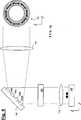
Im Weiteren wird zunächst unter Bezugnahme auf
Die Projektionsbelichtungsanlage gemäß
Gemäß der Erfindung ist Bestandteil der Beleuchtungseinrichtung
In Lichtausbreitungsrichtung vor der Spiegelanordnung
In Lichtausbreitungsrichtung nach der optischen Einheit
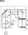
Im Weiteren wird das erfindungsgemäße Verfahren zum Betreiben der wie in
Dabei zeigen
Gemäß
Die Darstellung von
Selbstverständlich lassen sich durch geeignete Kombinationen von Drehstellung der Lambda/2-Platte
Im Ergebnis wird durch das vorstehend beschriebene Verfahren mit nur sehr geringem konstruktivem Aufwand (nämlich lediglich unter Bereitstellung einer mit einer geeigneten Drehmechanik versehenen Lambda/2-Platte in Kombination mit einer Spiegelanordnung) eine hohe Flexibilität hinsichtlich der Erzeugung unterschiedlicher Intensitäts- und Polarisationsverteilungen in der Pupillenebene der Beleuchtungseinrichtung erzielt.As a result, by the method described above with very little design effort (namely, only providing a provided with a suitable rotary mechanism lambda / 2 plate in combination with a mirror assembly) a high flexibility in terms of generating different intensity and polarization distributions in the pupil plane achieved the lighting device.
Wenn die Erfindung auch anhand spezieller Ausführungsformen beschrieben wurde, erschließen sich für den Fachmann zahlreiche Variationen und alternative Ausführungsformen, z. B. durch Kombination und/oder Austausch von Merkmalen einzelner Ausführungsformen. Dementsprechend versteht es sich für den Fachmann, dass derartige Variationen und alternative Ausführungsformen von der vorliegenden Erfindung mit umfasst sind, und die Reichweite der Erfindung nur im Sinne der beigefügten Patentansprüche und deren Äquivalente beschränkt ist.While the invention has been described with reference to specific embodiments, numerous variations and alternative embodiments will become apparent to those skilled in the art. B. by combination and / or exchange of features of individual embodiments. Accordingly, it will be understood by those skilled in the art that such variations and alternative embodiments are intended to be embraced by the present invention, and the scope of the invention is limited only in terms of the appended claims and their equivalents.
ZITATE ENTHALTEN IN DER BESCHREIBUNG QUOTES INCLUDE IN THE DESCRIPTION
Diese Liste der vom Anmelder aufgeführten Dokumente wurde automatisiert erzeugt und ist ausschließlich zur besseren Information des Lesers aufgenommen. Die Liste ist nicht Bestandteil der deutschen Patent- bzw. Gebrauchsmusteranmeldung. Das DPMA übernimmt keinerlei Haftung für etwaige Fehler oder Auslassungen.This list of the documents listed by the applicant has been generated automatically and is included solely for the better information of the reader. The list is not part of the German patent or utility model application. The DPMA assumes no liability for any errors or omissions.
Zitierte PatentliteraturCited patent literature
- WO 2005/026843 A2[0003]WO 2005/026843 A2[0003]
- WO 2005/069081 A2[0006]WO 2005/069081 A2[0006]
- WO 2005/031467 A2[0006]WO 2005/031467 A2[0006]
- US 6191880 B1[0006]US 6191880 B1[0006]
- US 2007/0146676 A1[0006]US 2007/0146676 A1[0006]
- WO 2009/034109 A2[0006]WO 2009/034109 A2[0006]
- WO 2008/019936 A2[0006]WO 2008/019936 A2[0006]
- WO 2009/100862 A1[0006]WO 2009/100862 A1[0006]
- DE 102008009601 A1[0006]DE 102008009601 A1[0006]
- DE 102004011733 A1[0006]DE 102004011733 A1[0006]
- EP 1306665 A2[0006]EP 1306665 A2[0006]
Claims (8)
Translated fromGermanPriority Applications (1)
| Application Number | Priority Date | Filing Date | Title |
|---|---|---|---|
| DE201310200137DE102013200137A1 (en) | 2013-01-08 | 2013-01-08 | Microlithographic projection exposure system operating method for manufacturing e.g. LCDs, involves illuminating regions of plane in rotational positions of lambda/two-plate, and adjusting mirror arrangement with light pulses |
Applications Claiming Priority (1)
| Application Number | Priority Date | Filing Date | Title |
|---|---|---|---|
| DE201310200137DE102013200137A1 (en) | 2013-01-08 | 2013-01-08 | Microlithographic projection exposure system operating method for manufacturing e.g. LCDs, involves illuminating regions of plane in rotational positions of lambda/two-plate, and adjusting mirror arrangement with light pulses |
Publications (1)
| Publication Number | Publication Date |
|---|---|
| DE102013200137A1true DE102013200137A1 (en) | 2013-11-14 |
Family
ID=49475668
Family Applications (1)
| Application Number | Title | Priority Date | Filing Date |
|---|---|---|---|
| DE201310200137WithdrawnDE102013200137A1 (en) | 2013-01-08 | 2013-01-08 | Microlithographic projection exposure system operating method for manufacturing e.g. LCDs, involves illuminating regions of plane in rotational positions of lambda/two-plate, and adjusting mirror arrangement with light pulses |
Country Status (1)
| Country | Link |
|---|---|
| DE (1) | DE102013200137A1 (en) |
Cited By (1)
| Publication number | Priority date | Publication date | Assignee | Title |
|---|---|---|---|---|
| US9720327B2 (en) | 2012-12-14 | 2017-08-01 | Carl Zeiss Smt Gmbh | Optical system of a microlithographic projection exposure apparatus |
Citations (12)
| Publication number | Priority date | Publication date | Assignee | Title |
|---|---|---|---|---|
| US6191880B1 (en) | 1995-09-23 | 2001-02-20 | Carl-Zeiss-Stiftung | Radial polarization-rotating optical arrangement and microlithographic projection exposure system incorporating said arrangement |
| EP1306665A2 (en) | 2001-10-26 | 2003-05-02 | Canon Kabushiki Kaisha | Optical apparatus |
| WO2005026843A2 (en) | 2003-09-12 | 2005-03-24 | Carl Zeiss Smt Ag | Illumination system for a microlithography projection exposure installation |
| WO2005031467A2 (en) | 2003-09-26 | 2005-04-07 | Carl Zeiss Smt Ag | Microlithographic projection exposure |
| WO2005069081A2 (en) | 2004-01-16 | 2005-07-28 | Carl Zeiss Smt Ag | Polarization-modulating optical element |
| DE102004011733A1 (en) | 2004-03-04 | 2005-09-22 | Carl Zeiss Smt Ag | Transmission filter apparatus |
| US20070146676A1 (en) | 2005-01-21 | 2007-06-28 | Nikon Corporation | Method of adjusting lighting optical device, lighting optical device, exposure system, and exposure method |
| WO2008019936A2 (en) | 2006-08-17 | 2008-02-21 | Carl Zeiss Smt Ag | Microlithographic projection exposure apparatus and microlithographic exposure method |
| WO2009034109A2 (en) | 2007-09-14 | 2009-03-19 | Carl Zeiss Smt Ag | Illumination system of a microlithographic projection exposure apparatus |
| US20090115990A1 (en)* | 2007-11-06 | 2009-05-07 | Nikon Corporation | Illumination optical apparatus, exposure apparatus, and device manufacturing method |
| WO2009100862A1 (en) | 2008-02-15 | 2009-08-20 | Carl Zeiss Smt Ag | Optcal system for a microlithographic projection exposure apparatus and microlithographic exposure method |
| US20090279066A1 (en)* | 2008-05-08 | 2009-11-12 | Asml Netherlands B.V. | Lithographic apparatus and method |
- 2013
- 2013-01-08DEDE201310200137patent/DE102013200137A1/ennot_activeWithdrawn
Patent Citations (13)
| Publication number | Priority date | Publication date | Assignee | Title |
|---|---|---|---|---|
| US6191880B1 (en) | 1995-09-23 | 2001-02-20 | Carl-Zeiss-Stiftung | Radial polarization-rotating optical arrangement and microlithographic projection exposure system incorporating said arrangement |
| EP1306665A2 (en) | 2001-10-26 | 2003-05-02 | Canon Kabushiki Kaisha | Optical apparatus |
| WO2005026843A2 (en) | 2003-09-12 | 2005-03-24 | Carl Zeiss Smt Ag | Illumination system for a microlithography projection exposure installation |
| WO2005031467A2 (en) | 2003-09-26 | 2005-04-07 | Carl Zeiss Smt Ag | Microlithographic projection exposure |
| WO2005069081A2 (en) | 2004-01-16 | 2005-07-28 | Carl Zeiss Smt Ag | Polarization-modulating optical element |
| DE102004011733A1 (en) | 2004-03-04 | 2005-09-22 | Carl Zeiss Smt Ag | Transmission filter apparatus |
| US20070146676A1 (en) | 2005-01-21 | 2007-06-28 | Nikon Corporation | Method of adjusting lighting optical device, lighting optical device, exposure system, and exposure method |
| WO2008019936A2 (en) | 2006-08-17 | 2008-02-21 | Carl Zeiss Smt Ag | Microlithographic projection exposure apparatus and microlithographic exposure method |
| WO2009034109A2 (en) | 2007-09-14 | 2009-03-19 | Carl Zeiss Smt Ag | Illumination system of a microlithographic projection exposure apparatus |
| US20090115990A1 (en)* | 2007-11-06 | 2009-05-07 | Nikon Corporation | Illumination optical apparatus, exposure apparatus, and device manufacturing method |
| WO2009100862A1 (en) | 2008-02-15 | 2009-08-20 | Carl Zeiss Smt Ag | Optcal system for a microlithographic projection exposure apparatus and microlithographic exposure method |
| DE102008009601A1 (en) | 2008-02-15 | 2009-08-20 | Carl Zeiss Smt Ag | Optical system for a microlithographic projection exposure apparatus and microlithographic exposure method |
| US20090279066A1 (en)* | 2008-05-08 | 2009-11-12 | Asml Netherlands B.V. | Lithographic apparatus and method |
Cited By (1)
| Publication number | Priority date | Publication date | Assignee | Title |
|---|---|---|---|---|
| US9720327B2 (en) | 2012-12-14 | 2017-08-01 | Carl Zeiss Smt Gmbh | Optical system of a microlithographic projection exposure apparatus |
Similar Documents
| Publication | Publication Date | Title |
|---|---|---|
| DE102010029905A1 (en) | Optical system of a microlithographic projection exposure apparatus | |
| DE102010029339A1 (en) | Optical system for a microlithographic projection exposure apparatus and microlithographic exposure method | |
| DE102008009601A1 (en) | Optical system for a microlithographic projection exposure apparatus and microlithographic exposure method | |
| DE102004013886A1 (en) | Multiple Exposure Method, Microlithography Projection Exposure System and Projection System | |
| DE102007027985A1 (en) | Optical system, in particular illumination device or projection objective of a microlithographic projection exposure apparatus | |
| DE102007042047A1 (en) | Subsystem of a lighting device of a microlithographic projection exposure apparatus | |
| DE102012206153A1 (en) | Optical system of a microlithographic projection exposure apparatus | |
| DE102011079837A1 (en) | Optical system for microlithographic projection exposure system for manufacturing e.g. LCDs, has beam-splitting optic element arranged such that degree of polarization of incident light beam is lesser than specified value | |
| DE102012206150B3 (en) | Optical system, in particular a microlithographic projection exposure apparatus | |
| DE102012223217B3 (en) | Optical system for use in illuminating device illuminating reticle in microlithographic projection exposure system to manufacture e.g. LCDs, has deflection device including reflection surfaces upstream and downstream of mirror arrangement | |
| DE102011003035A1 (en) | Polarization-influencing optical arrangement, as well as optical system of a microlithographic projection exposure apparatus | |
| DE102012214052A1 (en) | Microlithographic exposure method, and microlithographic projection exposure apparatus | |
| DE102011006003A1 (en) | Illumination optics for use in extreme UV-projection exposure system to illuminate illuminating field in reticle plane for manufacturing microstructured component, has aperture diaphragm adapting main beam direction relative to field | |
| WO2011095209A1 (en) | Microlithographic projection exposure system | |
| DE102023205340A1 (en) | Method for producing an optical element, as well as optical element and coating system | |
| DE102011085334A1 (en) | Optical system in a lighting device of a microlithographic projection exposure apparatus | |
| DE102012205045A1 (en) | Optical system of a microlithographic projection exposure apparatus | |
| DE102013200137A1 (en) | Microlithographic projection exposure system operating method for manufacturing e.g. LCDs, involves illuminating regions of plane in rotational positions of lambda/two-plate, and adjusting mirror arrangement with light pulses | |
| DE102007055063A1 (en) | Illumination device of a microlithographic projection exposure apparatus | |
| DE102013205957A1 (en) | Optical system for microlithographic projection exposure system that is utilized for manufacturing of e.g. integrated switching circuits, has light sources for illuminating reflecting surfaces with light of different polarization states | |
| DE102012213553A1 (en) | Optical system i.e. micro-lithographic projection exposure system, for manufacturing e.g. LCD, has lenses arranged relative to each other such that delay distribution is partly compensated by voltage-induced double refraction distribution | |
| DE102012217769A1 (en) | Optical system for a microlithographic projection exposure apparatus and microlithographic exposure method | |
| DE102012206148A1 (en) | Optical system of a microlithographic projection exposure apparatus, and method for adjusting an optical system | |
| DE102009016063A1 (en) | Micro lithographic projection exposure method for manufacturing e.g. LCD, involves projecting mask structure on region of layer using projection exposure apparatus, where regions are arranged in parts in optical path of illumination device | |
| DE102008013567A1 (en) | Lighting device for microlithographic projection exposure system, has optical element adjusting polarization conditions of radiations, where conditions are different from each other and radiations are deflected in different directions |
Legal Events
| Date | Code | Title | Description |
|---|---|---|---|
| R012 | Request for examination validly filed | ||
| R083 | Amendment of/additions to inventor(s) | ||
| R230 | Request for early publication | ||
| R120 | Application withdrawn or ip right abandoned | Effective date:20131212 |