DE102013114881A1 - Control system for a motor-driven closure element arrangement of a motor vehicle - Google Patents
Control system for a motor-driven closure element arrangement of a motor vehicleDownload PDFInfo
- Publication number
- DE102013114881A1 DE102013114881A1DE102013114881.6ADE102013114881ADE102013114881A1DE 102013114881 A1DE102013114881 A1DE 102013114881A1DE 102013114881 ADE102013114881 ADE 102013114881ADE 102013114881 A1DE102013114881 A1DE 102013114881A1
- Authority
- DE
- Germany
- Prior art keywords
- operator
- sensor
- longitudinal direction
- distance
- distance sensor
- Prior art date
- Legal status (The legal status is an assumption and is not a legal conclusion. Google has not performed a legal analysis and makes no representation as to the accuracy of the status listed.)
- Withdrawn
Links
Images


Classifications
- E—FIXED CONSTRUCTIONS
- E05—LOCKS; KEYS; WINDOW OR DOOR FITTINGS; SAFES
- E05F—DEVICES FOR MOVING WINGS INTO OPEN OR CLOSED POSITION; CHECKS FOR WINGS; WING FITTINGS NOT OTHERWISE PROVIDED FOR, CONCERNED WITH THE FUNCTIONING OF THE WING
- E05F15/00—Power-operated mechanisms for wings
- E05F15/70—Power-operated mechanisms for wings with automatic actuation
- E05F15/73—Power-operated mechanisms for wings with automatic actuation responsive to movement or presence of persons or objects
- E—FIXED CONSTRUCTIONS
- E05—LOCKS; KEYS; WINDOW OR DOOR FITTINGS; SAFES
- E05F—DEVICES FOR MOVING WINGS INTO OPEN OR CLOSED POSITION; CHECKS FOR WINGS; WING FITTINGS NOT OTHERWISE PROVIDED FOR, CONCERNED WITH THE FUNCTIONING OF THE WING
- E05F15/00—Power-operated mechanisms for wings
- E05F15/60—Power-operated mechanisms for wings using electrical actuators
- E—FIXED CONSTRUCTIONS
- E05—LOCKS; KEYS; WINDOW OR DOOR FITTINGS; SAFES
- E05Y—INDEXING SCHEME ASSOCIATED WITH SUBCLASSES E05D AND E05F, RELATING TO CONSTRUCTION ELEMENTS, ELECTRIC CONTROL, POWER SUPPLY, POWER SIGNAL OR TRANSMISSION, USER INTERFACES, MOUNTING OR COUPLING, DETAILS, ACCESSORIES, AUXILIARY OPERATIONS NOT OTHERWISE PROVIDED FOR, APPLICATION THEREOF
- E05Y2900/00—Application of doors, windows, wings or fittings thereof
- E05Y2900/50—Application of doors, windows, wings or fittings thereof for vehicles
- E05Y2900/53—Type of wing
- E05Y2900/548—Trunk lids
Landscapes
- Measurement Of Length, Angles, Or The Like Using Electric Or Magnetic Means (AREA)
- Power-Operated Mechanisms For Wings (AREA)
Abstract
Translated fromGermanDescription
Translated fromGermanDie Erfindung betrifft ein Steuersystem für eine motorische Verschlusselementanordnung eines Kraftfahrzeugs gemäß dem Oberbegriff von Anspruch 1 und eine Abstandssensoranordnung gemäß dem Oberbegriff von Anspruch 14.The invention relates to a control system for a motor-driven closure element arrangement of a motor vehicle according to the preamble of
Die heutigen Kraftfahrzeuge weisen zunehmend motorische Verschlusselementanordnungen mit mindestens einem Verschlusselement auf. Bei solchen Verschlusselementen kann es sich beispielsweise um Türen, insbesondere Schiebetüren, Klappen, insbesondere Heckklappen, Heckdeckel, Motorhauben, Laderaumböden o. dgl. eines Kraftfahrzeugs handeln. Insoweit ist der Begriff „Verschlusselement” vorliegend weit zu verstehen. Dem Verschlusselement ist regelmäßig eine Antriebsanordnung zugeordnet, die der motorischen Verstellung des Verschlusselements, dem motorischen Öffnen eines Kraftfahrzeugschlosses des Verschlusselements, o. dgl. dienen kann.Today's motor vehicles increasingly have motorized closure element arrangements with at least one closure element. Such closure elements may be, for example, doors, in particular sliding doors, flaps, in particular tailgates, trunk lids, engine hoods, load compartment floors or the like of a motor vehicle. In that regard, the term "closure element" is to be understood in the present case. The closure element is regularly associated with a drive arrangement which can serve for the motorized adjustment of the closure element, the motorized opening of a motor vehicle lock of the closure element, or the like.
Eine Komfortfunktion, der heute zunehmende Bedeutung zukommt, ist die automatische Betätigung der motorischen Heckklappe eines Kraftfahrzeugs. Das bekannte Steuersystem (
Das bekannte Steuersystem ist ferner mit einer Steuerungsanordnung ausgestattet, die im Rahmen einer Bedienereignisüberwachung den Abstandssensor daraufhin überwacht, ob ein vorbestimmtes Bedienereignis in Form eines Bediener-Bewegungszyklus vorliegt. Bei dem Bediener-Bewegungszyklus handelt es sich in einer Variante um einen Quer-Bewegungszyklus in Form einer Fußbewegung in einer Querrichtung. Auf eine Erfassung dieses Bedienereignisses kommt es zu einer Ansteuerung der Verschlusselementanordnung mittels der Steuerungsanordnung, sofern zusätzlich eine Längsbewegung des Bedieners in Längsrichtung erfasst worden ist. Damit kann sichergestellt werden, dass sich der Bediener bereits aus dem kollisionsgefährdeten Bereich heraus bewegt hat. Die Längsbewegung des Bedieners wird ebenfalls über den Abstandssensor erfasst. Hierfür weist der Abstandssensor entlang einer Sensorerstreckung eine sich verändernde Sensitivität auf.The known control system is further equipped with a control arrangement which, in the context of an operating event monitoring, monitors the distance sensor to determine whether a predetermined operating event exists in the form of an operator's movement cycle. In one variant, the operator movement cycle is a transverse movement cycle in the form of a foot movement in a transverse direction. Upon detection of this operating event, there is an activation of the closure element arrangement by means of the control arrangement, provided that a longitudinal movement of the operator in the longitudinal direction has additionally been detected. This can ensure that the operator has already moved out of the collision-prone area. The longitudinal movement of the operator is also detected by the distance sensor. For this purpose, the distance sensor has a changing sensitivity along a sensor extension.
In der
Eine ähnliche Offenbarung ergibt sich aus der
Nachteilig bei den bekannten Steuersystemen ist die Tatsache, dass der Bediener einen relativ eng vorgegebenen Bediener-Bewegungszyklus einhalten muss, um die gewünschte Ansteuerung des jeweiligen Verschlusselements auszulösen. Dies ist als Einschränkung des Bedienkomforts zu verstehen.A disadvantage of the known control systems is the fact that the operator must comply with a relatively narrow predetermined operator movement cycle in order to trigger the desired activation of the respective closure element. This is to be understood as a restriction of the ease of use.
Der Erfindung liegt das Problem zugrunde, das bekannte Steuersystem derart auszugestalten und weiterzubilden, dass sich der Bedienkomfort mit einfachen Mitteln steigern lässt.The invention is based on the problem, the known control system in such a way and further develop that the ease of use can be increased with simple means.
Das obige Problem wird bei einem Steuersystem gemäß dem Oberbegriff von Anspruch 1 durch die Merkmale des kennzeichnenden Teils von Anspruch 1 gelöst.The above problem is solved in a control system according to the preamble of
Wesentlich ist zunächst die Überlegung, dass die Steuerungsanordnung einen vorbestimmten, in Längsrichtung verlaufenden Längs-Bewegungszyklus eines Körperteils eines Bedieners im Rahmen der Bedienereignisüberwachung nicht nur als ein Bedienereignis erfasst, sondern auf diese Erfassung hin auch eine Ansteuerung der Verschlusselementanordnung vornimmt. Es ist also in einem ersten Schritt erkannt worden, dass ein Längs-Bewegungszyklus als solcher geeignet ist, eine Ansteuerung der Verschlusselementanordnung auszulösen. Beispielsweise ist es denkbar, einen Quer-Bewegungszyklus zusätzlich in der Längsrichtung zuzulassen und als Bedienereignis zu erfassen. Damit müsste der Bediener nicht mehr darauf achten, ob er den vorgegebenen Bewegungszyklus nun in Querrichtung oder in Längsrichtung ausführt.What is important at first is the consideration that the control arrangement not only detects a predetermined, longitudinally extending longitudinal movement cycle of a body part of an operator within the context of the operation event monitoring as an operating event, but also carries out an activation of the closure element arrangement in response to this detection. It has therefore been recognized in a first step that a longitudinal movement cycle as such is suitable for triggering the closure element arrangement. For example, it is conceivable to additionally allow a transverse movement cycle in the longitudinal direction and to detect it as an operating event. Thus, the operator would no longer have to pay attention to whether he performs the given movement cycle now in the transverse direction or in the longitudinal direction.
Wesentlich ist weiter, dass die sensorische Erfassung des Längs-Bewegungszyklus eines Körperteils des Bedieners unproblematisch ist, sofern der Abstandssensor in bestimmter Weise konfiguriert ist. Im Einzelnen wird hierzu vorgeschlagen, dass der Abstandssensor zur Längsbewegungserfassung eine sich entlang der Längsrichtung mit einer Periodenlänge periodisch verändernde Sensorkonfiguration aufweist, so dass sich das in Längsrichtung bewegende Körperteil des Bedieners sich verändernde Sensormesswerte des Abstandssensors erzeugt. Von besonderer Bedeutung ist dabei, dass die Periodenlänge mindestens der Ausdehnung des Längs-Bewegungszyklus in Längsrichtung entspricht. Dies bedeutet, dass sich ein Längs-Bewegungszyklus in etwa innerhalb dieser Periodenlänge befindet, so dass sich periodisch wiederholende Sensormesswerte aufgrund der sich periodisch verändernden Sensorkonfiguration ausbleiben. Dies würde zu Mehrdeutigkeiten in der Auswertung der Sensormesswerte führen und die Erfassung eines Bedienereignisses aufwendig gestalten. Im Gegensatz dazu lässt sich hier der Längs-Bewegungszyklus mit einfachen steuerungstechnischen Mitteln als Bedienereignis erfassen.It is also essential that the sensory detection of the longitudinal movement cycle of a body part of the operator is unproblematic if the distance sensor is configured in a specific way. In detail, it is proposed for this purpose that the distance sensor for longitudinal movement detection has a sensor configuration which changes periodically along the longitudinal direction with a period length, so that the longitudinally moving body part of the operator generates changing sensor measured values of the distance sensor. Of particular importance is that the Period length at least equal to the extension of the longitudinal movement cycle in the longitudinal direction. This means that a longitudinal motion cycle is approximately within this period length, so that periodically repeating sensor readings fail due to the periodically changing sensor configuration. This would lead to ambiguities in the evaluation of the sensor measured values and make the acquisition of an operating event expensive. In contrast to this, the longitudinal movement cycle can be detected here as a control event with simple control engineering means.
Im Ergebnis lässt sich mit der vorschlagsgemäßen Lösung der Bedienkomfort mit geringem Aufwand und damit kostengünstig umsetzen.As a result, with the proposed solution, the ease of use with little effort and thus can be implemented inexpensively.
Der Begriff „Sensorkonfiguration” ist wert zu verstehen und umfasst jeden Parameter, der einen Einfluss auf die Sensormesswerte des Abstandssensors ausübt. Entsprechend geht die Sensorkonfiguration eines Abstandssensors auf seine Geometrie, seine Lage, seine Materialzusammensetzung, eventuelle Abschirmmaßnahmen o. dgl. zurück.The term "sensor configuration" is to be understood and includes any parameter that exerts an influence on the sensor readings of the proximity sensor. Accordingly, the sensor configuration of a distance sensor is based on its geometry, its position, its material composition, possible shielding measures or the like.
Bei den besonders bevorzugten Ausgestaltungen gemäß den Ansprüchen 5 und 6 verläuft der Abstandssensor im Rahmen der sich verändernden Sensorkonfiguration entlang der Längsrichtung alternierend um eine Mittellinie. Interessant dabei ist die Tatsache, dass sich die Sensorkonfiguration schlicht durch eine spezielle Verlegung des Abstandssensors erreichen lässt, ohne dass irgendwelche Eingriffe in den Aufbau des Abstandssensors selbst erfolgen müssen. Eine wellenförmige Verlegung des Abstandssensors hat sich in diesem Zusammenhang als besonders vorteilhaft herausgestellt, da die resultierenden Messwertverläufe vergleichsweise einfach auszuwerten sind.In the particularly preferred embodiments according to
Für den Fall, dass zwei Abstandssensoren vorgesehen sind, die nebeneinander verlaufen, führt die Ausgestaltung gemäß Anspruch 7 zu einer weiteren Vereinfachung der Auswertung der Sensormesswerte. Dies liegt daran, dass ein Zeitversatz zwischen den Sensormesswerten der beiden Abstandssensoren eine Charakteristik eines Längs-Bewegungszyklus sein kann, die auf besonders einfache Weise erfassbar ist. Gemäß Anspruch 8 wird hierzu beispielsweise vorgeschlagen, den Zeitversatz zwischen zwei Messwertimpulsen der Abstandssensoren daraufhin zu überprüfen, ob ein zeitlicher Mindestversatz vorliegt. Bejahendenfalls wäre eine notwendige Bedingung für die Erfassung des Längs-Bewegungszyklus als Bedienereignis erfüllt.In the event that two distance sensors are provided, which run next to each other, the embodiment according to
Bei den weiter bevorzugten Ausgestaltungen gemäß den Ansprüchen 9 und 10 handelt es sich bei zumindest einem Abstandssensor um einen kapazitiven Abstandssensor. Gemäß Anspruch 10 kann die Messelektrode des Abstandssensors als Rundleiter ausgestaltet sein und in die alternierende Form gebogen sein. Alternativ kann es aber auch vorgesehen sein, dass ein Abstandssensor als Flachleiter ausgestaltet ist und in die alternierende Form vorgeformt, beispielsweise ausgestanzt, ist. In beiden Fällen lässt sich die alternierende Form mit minimalen Kosten umsetzen.In the further preferred embodiments according to
Eine Alternative für die Realisierung der sich entlang der Längsrichtung verändernden Sensorkonfiguration zeigen die Ansprüche 11 und 12. Hier ist dem Abstandssensor eine Abschirmanordnung zugeordnet, um das kapazitive Messfeld abschnittsweise zu verändern, was sich wiederum auf die Sensormesswerte auswirkt. Bei der einfach zu realisierenden Ausgestaltung gemäß Anspruch 12 wird der Abstandssensor abschnittsweise mit entsprechenden Abschirmblechen versehen.An alternative for the realization of the sensor configuration changing along the longitudinal direction is shown in
Eine besonders einfache sensorische Erfassung sowohl eines Längs-Bewegungszyklus als auch eines Quer-Bewegungszyklus ist Gegenstand von Anspruch 13. Dies liegt daran, dass beide Bewegungszyklen, ggf. nach einer Normierung, Sensormesswertverläufe eines Abstandssensors mit im Wesentlichen gleichen Signalformen erzeugen. Im einfachsten Fall kann derselbe Erkennungsalgorithmus für den Längs-Bewegungszyklus und den Quer-Bewegungszyklus Anwendung finden.A particularly simple sensory detection of both a longitudinal movement cycle and a transverse movement cycle is the subject matter of claim 13. This is because both movement cycles, possibly after normalization, generate sensor measured value profiles of a distance sensor with essentially the same signal forms. In the simplest case, the same recognition algorithm can be used for the longitudinal motion cycle and the transverse motion cycle.
Nach einer weiteren Lehre, der ebenfalls eigenständige Bedeutung zukommt, wird eine Abstandssensoranordnung gemäß Anspruch 14 beansprucht.According to another teaching, which also has independent significance, a distance sensor arrangement according to claim 14 is claimed.
Wesentlich für die weitere Lehre ist die Tatsache, dass zwei Abstandssensoren vorgesehen sind, die zur Längsbewegungserfassung jeweils eine sich entlang der Längsrichtung mit einer Periodenlänge periodisch verändernde Sensorkonfiguration aufweisen, so dass ein sich in Längsrichtung bewegendes Körperteil des Bedieners sich verändernde Sensormesswerte der Abstandssensoren erzeugt, wobei die beiden Abstandssensoren parallel zueinander verlaufen. Der Vorteil der einfachen Auswertung der Sensormesswerte bei einer solchen parallelen Anordnung der Abstandssensoren wurde weiter oben bereits angesprochen. Auf die Mindest-Periodenlänge gemäß der erstgenannten Lehre kommt es hier allerdings nicht an.Essential for the further teaching is the fact that two distance sensors are provided which each have a sensor configuration that varies periodically along the longitudinal direction along the longitudinal direction so that a longitudinally moving body part of the operator generates changing sensor measured values of the distance sensors the two distance sensors run parallel to each other. The advantage of the simple evaluation of the sensor measured values in such a parallel arrangement of the distance sensors has already been mentioned above. However, the minimum period length according to the first-mentioned teaching does not matter here.
Im Folgenden wird die Erfindung anhand einer lediglich ein Ausführungsbeispiel darstellenden Zeichnung näher erläutert. In der Zeichnung zeigtIn the following the invention will be explained in more detail with reference to a drawing showing only one exemplary embodiment. In the drawing shows
Das vorschlagsgemäße Steuersystem
Die Ausgestaltung des Verschlusselements
Zur Erfassung von Bedienereignissen in Form von Bediener-Bewegungszyklen weist das Steuersystem
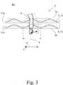
Der mindestens eine Abstandssensor
Die obigen Bewegungszyklen umfassen vorbestimmte Bewegungen des Bedieners B, die als Bedienereignis erfasst werden sollen. Dabei handelt es sich vorzugsweise um Bewegungen eines Körperteils, insbesondere eines Beins b, eines Bedieners B, wie noch erläutert wird. Der Begriff „linienartiger Abstandssensor” ist vorliegend weit zu verstehen und umfasst alle Abstandssensoren mit langgestreckter Formgebung. Darunter fallen insbesondere Abstandssensoren mit drahtartigen Messelektroden.The above movement cycles include predetermined movements of the operator B to be detected as an operation event. These are preferably movements of a body part, in particular a leg b, an operator B, as will be explained. The term "linear distance sensor" is to be understood in the present case and includes all distance sensors with elongated shape. These include in particular distance sensors with wire-like measuring electrodes.
Die linienartigen Abstandssensoren
Grundsätzlich kann lediglich ein einziger Abstandssensor
Es lässt sich den Darstellungen gemäß den
Das Steuersystem
Die Bedienereignisüberwachung kann einerseits über die gemessenen Abstandswerte erfolgen. Bei dem vorschlagsgemäßen Steuersystem
Interessant bei der vorschlagsgemäßen Lösung ist zunächst, dass die Steuerungsanordnung
Interessant ist weiter die vorschlagsgemäße Art und Weise der Längsbewegungserfassung. Vorschlagsgemäß ist es nämlich so, dass mindestens ein Abstandssensor
Bei dem in
Interessant bei der vorschlagsgemäßen Lösung ist schließlich, dass die Periodenlänge
Neben der Erfassung des Längs-Bewegungszyklus als Bedienereignis ist es vorzugsweise so, dass auch ein in der Querrichtung
Es darf darauf hingewiesen werden, dass der Längs-Bewegungszyklus und der Quer-Bewegungszyklus in Längsrichtung
In besonders bevorzugter Ausgestaltung ist die Verschlusselementanordnung
Die Steuerungsanordnung
Ein besonders hoher Bedienkomfort lässt sich dadurch erreichen, dass die Steuerungsanordnung
Besonders praxisgerecht ist die vorschlagsgemäße Lösung für den Fall, dass der Quer-Bewegungszyklus und/oder der Längs-Bewegungszyklus eine Hin- und Rückbewegung des Körperteils des Bedieners B, insbesondere des Beins b des Bedieners B, umfasst bzw. umfassen. Der Quer-Bewegungszyklus umfasst dann regelmäßig eine sogenannte „Kickbewegung” in Querrichtung
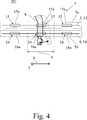
Für die Realisierung der vorschlagsgemäßen, sich entlang der Längsrichtung
Für die konkrete Formgebung des alternierend verlaufenden Abstandssensors
Der mindestens eine Abstandssensor
Es lässt sich der Darstellung gemäß
Der obige Zeitversatz kann neben anderen Auswertungskriterien eine notwendige Bedingung für die Erfassung des Längs-Bewegungszyklus als Bedienereignis darstellen. Im Einzelnen ist es vorzugsweise so, dass der Längs-Bewegungszyklus in den Sensormesswerten beider Abstandssensoren
In besonders bevorzugter Ausgestaltung ist zumindest ein Abstandssensor
Sofern die mindestens eine Messelektrode
Eine andere bevorzugte Variante für die Erzeugung der sich entlang der Längsrichtung
Eine besonders bevorzugte Auslegung des Steuersystems
Nach einer weiteren Lehre, der eigenständige Bedeutung zukommt, wird eine Abstandssensoranordnung für ein Steuersystem
Zur Erfassung von Bedienereignissen in Form von Bediener-Bewegungszyklen sind zwei linienartige, quer zu ihrer lokalen Erstreckung abstandsmessende Abstandssensoren
Besonders vorteilhaft ist im Rahmen der weiteren Lehre eine Ausgestaltung, bei der die beiden Abstandssensoren
Auf alle Ausführungen zu der Ausgestaltung der Abstandssensoren
ZITATE ENTHALTEN IN DER BESCHREIBUNG QUOTES INCLUDE IN THE DESCRIPTION
Diese Liste der vom Anmelder aufgeführten Dokumente wurde automatisiert erzeugt und ist ausschließlich zur besseren Information des Lesers aufgenommen. Die Liste ist nicht Bestandteil der deutschen Patent- bzw. Gebrauchsmusteranmeldung. Das DPMA übernimmt keinerlei Haftung für etwaige Fehler oder Auslassungen.This list of the documents listed by the applicant has been generated automatically and is included solely for the better information of the reader. The list is not part of the German patent or utility model application. The DPMA assumes no liability for any errors or omissions.
Zitierte PatentliteraturCited patent literature
- DE 102011112274 A1[0003, 0005]DE 102011112274 A1[0003, 0005]
- DE 102010002559 A1[0006]DE 102010002559 A1[0006]
Claims (15)
Translated fromGermanPriority Applications (3)
| Application Number | Priority Date | Filing Date | Title |
|---|---|---|---|
| DE102013114881.6ADE102013114881A1 (en) | 2013-12-25 | 2013-12-25 | Control system for a motor-driven closure element arrangement of a motor vehicle |
| US14/581,441US9574388B2 (en) | 2013-12-25 | 2014-12-23 | Control system for a motorized closure element arrangement of a motor vehicle |
| CN201410818663.4ACN104746998B (en) | 2013-12-25 | 2014-12-25 | The control system of the blocking element component driven for the motor of motor vehicle |
Applications Claiming Priority (1)
| Application Number | Priority Date | Filing Date | Title |
|---|---|---|---|
| DE102013114881.6ADE102013114881A1 (en) | 2013-12-25 | 2013-12-25 | Control system for a motor-driven closure element arrangement of a motor vehicle |
Publications (1)
| Publication Number | Publication Date |
|---|---|
| DE102013114881A1true DE102013114881A1 (en) | 2015-06-25 |
Family
ID=53275090
Family Applications (1)
| Application Number | Title | Priority Date | Filing Date |
|---|---|---|---|
| DE102013114881.6AWithdrawnDE102013114881A1 (en) | 2013-12-25 | 2013-12-25 | Control system for a motor-driven closure element arrangement of a motor vehicle |
Country Status (3)
| Country | Link |
|---|---|
| US (1) | US9574388B2 (en) |
| CN (1) | CN104746998B (en) |
| DE (1) | DE102013114881A1 (en) |
Cited By (7)
| Publication number | Priority date | Publication date | Assignee | Title |
|---|---|---|---|---|
| US9574388B2 (en) | 2013-12-25 | 2017-02-21 | Brose Fahrzeugteile Gmbh & Co. Kg, Hallstadt | Control system for a motorized closure element arrangement of a motor vehicle |
| US9637087B2 (en) | 2011-09-05 | 2017-05-02 | Brose Fahrzeugteile Gmbh & Co. Kg, Hallstadt | Control system |
| US9725942B2 (en) | 2012-07-02 | 2017-08-08 | Brose Fahrzeugteile Gmbh & Co. Kg, Hallstadt | Method for controlling a closing element arrangement on a motor vehicle |
| US9920564B2 (en) | 2013-12-25 | 2018-03-20 | Brose Fahrzeugteile Gmbh & Co. Kg, Hallstadt | Control system for a motorized closure element arrangement of a motor vehicle |
| US10429430B2 (en) | 2015-11-15 | 2019-10-01 | Brose Fahrzeugteile Gmbh & Co. Kg, Bamberg | Method for operating a capacitive sensor arrangement of a motor vehicle |
| US10563447B2 (en) | 2011-12-21 | 2020-02-18 | Brose Fahrzeugteile Gmbh & Co. Kg, Hallstadt | Control system |
| US10774575B2 (en) | 2015-07-31 | 2020-09-15 | Brose Fahrzeugteile Gmbh & Co. Kommanditgesellschaft, Bamberg | Control system for a motor-displaceable cargo compartment device of a motor vehicle |
Families Citing this family (8)
| Publication number | Priority date | Publication date | Assignee | Title |
|---|---|---|---|---|
| CN105133994B (en)* | 2015-07-16 | 2017-03-22 | 广州汽车集团股份有限公司 | Trunk opening method and automatic induction opening system for trunk |
| JP2017150942A (en)* | 2016-02-24 | 2017-08-31 | アイシン精機株式会社 | Manipulation detection device for vehicles |
| DE102016108702A1 (en)* | 2016-05-11 | 2017-11-16 | Brose Fahrzeugteile Gmbh & Co. Kg, Bamberg | Method for controlling a motor-driven closure element arrangement of a motor vehicle |
| JP6737122B2 (en)* | 2016-10-19 | 2020-08-05 | アイシン精機株式会社 | Vehicle door operation detection device |
| JP6805813B2 (en)* | 2016-12-26 | 2020-12-23 | アイシン精機株式会社 | Electrostatic sensor |
| US20200362603A1 (en)* | 2019-05-16 | 2020-11-19 | GM Global Technology Operations LLC | Vehicle door with user gesture detection |
| CN111746463A (en)* | 2020-06-05 | 2020-10-09 | 领科汇智科技有限公司 | A leg sweeping action recognition method of a sweeping leg induction device |
| CN111894387A (en)* | 2020-07-28 | 2020-11-06 | 重庆长安汽车股份有限公司 | Automatic opening method and system for automobile trunk and vehicle |
Citations (2)
| Publication number | Priority date | Publication date | Assignee | Title |
|---|---|---|---|---|
| DE102010002559A1 (en) | 2010-03-03 | 2011-09-08 | Huf Hülsbeck & Fürst Gmbh & Co. Kg | Capacitive sensor arrangement for detection of e.g. door opening of motor car, has sensing electrode arrangements formed of elongated segments which are arranged in longitudinal direction to enable different capacitive detections |
| DE102011112274A1 (en) | 2011-09-05 | 2013-03-07 | Brose Fahrzeugteile Gmbh & Co. Kg, Hallstadt | control system |
Family Cites Families (79)
| Publication number | Priority date | Publication date | Assignee | Title |
|---|---|---|---|---|
| US4867059A (en) | 1988-08-05 | 1989-09-19 | International Business Machines Corporation | Impact printer print mechanism and method of manufacture |
| JP3200172B2 (en) | 1992-07-02 | 2001-08-20 | キヤノン株式会社 | Moving direction detection method |
| DE9421122U1 (en) | 1994-11-10 | 1995-04-27 | Horst Siedle Kg, 78120 Furtwangen | Device for determining a respective local position of a body |
| US5844486A (en) | 1997-01-02 | 1998-12-01 | Advanced Safety Concepts, Inc. | Integral capacitive sensor array |
| US6275146B1 (en) | 1996-04-23 | 2001-08-14 | Philip W. Kithil | Vehicle occupant sensing |
| US6535200B2 (en) | 1999-01-25 | 2003-03-18 | Harald Philipp | Capacitive position sensor |
| JP3754285B2 (en)* | 2000-09-27 | 2006-03-08 | 株式会社大井製作所 | Automatic door opening and closing device |
| US6411054B1 (en) | 2000-12-15 | 2002-06-25 | Ford Global Technologies, Inc. | Obstruction detection system for power liftgate |
| US6748308B2 (en) | 2001-03-30 | 2004-06-08 | Siemens Vdo Automotive Corporation | Automated closure system and method |
| DE10117935A1 (en)* | 2001-04-10 | 2002-10-17 | Valeo Sicherheitssysteme Gmbh | Automatic actuation method for vehicle door involves detecting actual door speed and regulating to bring door to second position at speed defined by desired value curve |
| GB2376075A (en) | 2001-06-01 | 2002-12-04 | Ab Automotive Electronics Ltd | Bumper proximity detector using capacitive sensor |
| WO2002101929A2 (en) | 2001-06-08 | 2002-12-19 | Intier Automative Closures, Inc. | Non-contact proximity sensor |
| US8225458B1 (en)* | 2001-07-13 | 2012-07-24 | Hoffberg Steven M | Intelligent door restraint |
| DE10235925A1 (en) | 2002-08-06 | 2004-02-19 | Valeo Schalter Und Sensoren Gmbh | Vehicle environment monitoring system and automatic vehicle door opening device |
| US6774642B2 (en) | 2002-08-27 | 2004-08-10 | Delphi Technologies, Inc. | Capacitive angular position sensor |
| DE10254708A1 (en) | 2002-11-23 | 2004-06-03 | Adam Opel Ag | Method for remote opening and closing of a rear flap of a motor vehicle and device therefor |
| JP2004270142A (en)* | 2003-03-05 | 2004-09-30 | Mitsuba Corp | Automatic opening and closing device for vehicle |
| US20050114276A1 (en) | 2003-11-20 | 2005-05-26 | Hunter Valerie K. | Personal customization of stamps |
| DE102004008928A1 (en) | 2004-02-24 | 2005-09-08 | Bayerische Motoren Werke Ag | Method for coupling a trailer using a vehicle level control |
| FR2866612B1 (en) | 2004-02-25 | 2006-05-05 | Renault Sas | VEHICLE HAVING A LOAD CARRIER |
| FR2868526B1 (en) | 2004-04-06 | 2007-04-20 | Peugeot Citroen Automobiles Sa | SENSOR FOR POSITIONING A VALVE ACTUATOR OF AN INTERNAL COMBUSTION ENGINE |
| JP4610300B2 (en) | 2004-11-02 | 2011-01-12 | 富士通テン株式会社 | VEHICLE CONTROL DEVICE AND VEHICLE CONTROL METHOD |
| DE102004055982A1 (en) | 2004-11-19 | 2006-06-01 | Daimlerchrysler Ag | Locking system for a vehicle |
| DE102004057220B4 (en) | 2004-11-26 | 2011-07-21 | Audi Ag, 85057 | Method and device for distinguishing a trailer from a carrier device at the rear of a vehicle |
| DE102005002046B4 (en)* | 2005-01-14 | 2009-02-05 | Dorma Gmbh + Co. Kg | Sliding door with a magnetic drive system with a displacement encoder |
| US7354097B2 (en) | 2005-05-25 | 2008-04-08 | Gm Global Technology Operations, Inc. | Power-actuated closure system |
| DE102005032402B3 (en) | 2005-07-12 | 2006-09-28 | Daimlerchrysler Ag | Person or object`s approach detecting method for object e.g. motor vehicle, involves optoelectronically monitoring whether person/object proceeds from position in zone that is remote from object e.g. vehicle, to nearer zone |
| DE102005042402A1 (en) | 2005-09-06 | 2007-03-08 | Bayerische Motoren Werke Ag | Motor vehicle with automatically opening flap |
| US8179435B2 (en) | 2005-09-28 | 2012-05-15 | Nissan Motor Co., Ltd. | Vehicle surroundings image providing system and method |
| DE102005055002B4 (en) | 2005-11-18 | 2024-05-16 | Bayerische Motoren Werke Aktiengesellschaft | Motor vehicle with automatically opening or closing flap |
| DE202005020140U1 (en) | 2005-12-22 | 2007-05-10 | BROSE SCHLIEßSYSTEME GMBH & CO. KG | Motor vehicle door assembly |
| JP2007228640A (en) | 2006-02-21 | 2007-09-06 | Combi Corp | Oscillator |
| DE102006030986B4 (en)* | 2006-07-03 | 2012-01-19 | Edscha Engineering Gmbh | Device and method for controlling a vehicle door or a vehicle door |
| DE102006044112A1 (en) | 2006-09-20 | 2008-03-27 | Hella Kgaa Hueck & Co. | Motor vehicle with a sensor arrangement |
| JP2008238992A (en)* | 2007-03-28 | 2008-10-09 | Honda Motor Co Ltd | Capacitive sensor mounting structure and assembly method thereof |
| FR2917771B1 (en) | 2007-06-25 | 2009-09-04 | Valeo Securite Habitacle Sas | SECURE METHOD OF AUTOMATICALLY CLOSING A MOTOR VEHICLE TAILGATE |
| DE102007030496B4 (en)* | 2007-06-30 | 2012-04-26 | Stabilus Gmbh | Motor vehicle with a cargo compartment closure flap |
| DE102007035904B4 (en) | 2007-07-31 | 2009-09-17 | Continental Automotive Gmbh | User identification device |
| WO2009027819A2 (en) | 2007-08-30 | 2009-03-05 | Thomas Frommer | System and method for dynamic braking a vehicle closure system |
| JP5309515B2 (en) | 2007-09-25 | 2013-10-09 | アイシン精機株式会社 | Vehicle door opening / closing control device |
| US7880481B2 (en) | 2007-12-19 | 2011-02-01 | Infineon Technologies Ag | Capacitive sensor and measurement system |
| JP2009175045A (en) | 2008-01-25 | 2009-08-06 | Denso Corp | Periphery monitoring device |
| JP5177510B2 (en) | 2008-03-27 | 2013-04-03 | アイシン精機株式会社 | Ultrasonic sensor |
| DE202009018206U1 (en) | 2008-04-29 | 2011-05-05 | Volkswagen Ag | Device for actuating a door or flap of a vehicle |
| DE102008041354A1 (en) | 2008-08-19 | 2010-02-25 | Robert Bosch Gmbh | Method for automatic opening of door e.g. sliding door, of motor vehicle e.g. car, in narrow place e.g. basement garage, involves passing vehicle door till into collision free opening position in reference to obstacle |
| DE102008063366B4 (en) | 2008-12-30 | 2022-04-28 | Huf Hülsbeck & Fürst Gmbh & Co. Kg | Device for contactless actuation of a tailgate of a motor vehicle and method for actuating a tailgate of a motor vehicle and motor vehicle |
| DE102009004155A1 (en) | 2009-01-09 | 2010-07-15 | Eilenburger Elektrolyse- Und Umwelttechnik Gmbh | Process and apparatus for regenerating peroxodisulfate pickling solutions |
| DE202009000907U1 (en)* | 2009-01-23 | 2010-06-17 | Brose Fahrzeugteile Gmbh & Co. Kommanditgesellschaft, Hallstadt | Drive arrangement for the motorized adjustment of an adjusting element of a motor vehicle |
| FR2943190B1 (en) | 2009-03-13 | 2016-12-30 | Valeo Securite Habitacle | DEVICE FOR TRIGGERING AN ACTION ON AN OPENING OF A MOTOR VEHICLE |
| JP5569712B2 (en) | 2009-03-30 | 2014-08-13 | アイシン精機株式会社 | Door control device |
| US9051769B2 (en) | 2009-08-21 | 2015-06-09 | Uusi, Llc | Vehicle assembly having a capacitive sensor |
| US9845629B2 (en) | 2009-08-21 | 2017-12-19 | Uusi, Llc | Vehicle keyless entry assembly having capacitance sensor operative for detecting objects |
| DE102009047066A1 (en) | 2009-11-24 | 2011-05-26 | Robert Bosch Gmbh | A method for warning of an object in the vicinity of a vehicle and driving assistant system |
| DE102009055778B4 (en) | 2009-11-25 | 2021-05-27 | Audi Ag | Method for operating a mechanism for opening a tailgate and a motor vehicle with a tailgate |
| DE102010006213A1 (en) | 2010-01-29 | 2011-08-04 | Bayerische Motoren Werke Aktiengesellschaft, 80809 | Control device for a vehicle with automatically opening and / or automatically closing flap |
| DE102010009058A1 (en)* | 2010-02-23 | 2011-08-25 | Brose Fahrzeugteile GmbH & Co. KG, Hallstadt, 96103 | Method for operating the electrical system of a motor vehicle |
| DE102010011767A1 (en)* | 2010-03-17 | 2011-09-22 | Brose Fahrzeugteile Gmbh & Co. Kg, Hallstadt | Method for sensory detection of an operator event |
| DE102010038687A1 (en)* | 2010-07-30 | 2012-02-02 | Bayerische Motoren Werke Aktiengesellschaft | Control device for a vehicle with automatically closing flap |
| DE102010034203B3 (en)* | 2010-08-12 | 2011-11-10 | Brose Fahrzeugteile Gmbh & Co. Kommanditgesellschaft, Hallstadt | Drive arrangement for the motorized adjustment of a flap arrangement |
| DE102010048144A1 (en) | 2010-10-11 | 2011-07-28 | Daimler AG, 70327 | Vehicle i.e. lorry, has sensor arranged such that surrounding area of vehicle is detectable, where surrounding area extends in sections along long side, runs over entire length of long side and runs in sections in region before front side |
| US9081032B2 (en) | 2010-10-22 | 2015-07-14 | Huf Huelsbeck & Fuerst Gmbh & Co. Kg | Capacitive sensor arrangement for switching a door opening on a motor vehicle |
| DE102010049400A1 (en) | 2010-10-26 | 2012-04-26 | Brose Fahrzeugteile Gmbh & Co. Kommanditgesellschaft, Hallstadt | Sensor unit for contactless actuation of a vehicle door |
| DE102010054975B3 (en)* | 2010-12-20 | 2012-02-23 | Brose Fahrzeugteile Gmbh & Co. Kg, Hallstadt | Procedure for operating flap arrangement of motor vehicle, involves controlling motor vehicle lock and damper actuator based on concluding condition such that interference holding of lock with concluding wedge is avoided or prevented |
| DE102010055297A1 (en)* | 2010-12-21 | 2012-06-21 | Brose Fahrzeugteile Gmbh & Co. Kommanditgesellschaft, Hallstadt | Method for generating an operator message when an operator event occurs |
| US8977507B2 (en) | 2011-01-21 | 2015-03-10 | The United States Of America As Represented By The Secretary Of The Navy | Event detection system user interface system coupled to multiple sensors including an impact detection system |
| DE102011018849B4 (en)* | 2011-04-27 | 2015-07-23 | Brose Fahrzeugteile Gmbh & Co. Kommanditgesellschaft, Hallstadt | Method for controlling a motorized flap arrangement of a motor vehicle |
| DE102011018847A1 (en) | 2011-04-27 | 2012-10-31 | Brose Fahrzeugteile Gmbh & Co. Kommanditgesellschaft, Hallstadt | Method for controlling a closure element arrangement of a motor vehicle |
| DE102011051434A1 (en) | 2011-06-29 | 2013-01-03 | Huf Hülsbeck & Fürst Gmbh & Co. Kg | Capacitive sensor arrangement and method for detecting actuation gestures on a motor vehicle |
| DE102011121775B3 (en) | 2011-12-21 | 2013-01-31 | Brose Fahrzeugteile Gmbh & Co. Kg, Hallstadt | Control system for controlling e.g. motorized side door of motor car, has distance sensors with dummy portions such that sensors comprise no sensitivity or smaller sensitivity compared to region of each sensor adjacent to dummy portions |
| DE102012008530A1 (en) | 2012-05-02 | 2013-11-07 | Brose Fahrzeugteile Gmbh & Co. Kg, Hallstadt | Method for controlling a closure element arrangement of a motor vehicle |
| DE102012013065A1 (en) | 2012-07-02 | 2014-01-02 | Brose Fahrzeugteile Gmbh & Co. Kg, Hallstadt | Method for controlling a closure element arrangement of a motor vehicle |
| DE102012014676A1 (en)* | 2012-07-25 | 2014-01-30 | Brose Fahrzeugteile Gmbh & Co. Kg, Hallstadt | Method for controlling a closure element arrangement, in particular of a motor vehicle |
| JP6018547B2 (en) | 2013-07-09 | 2016-11-02 | 大成ロテック株式会社 | Paving machine |
| DE102013018593B4 (en) | 2013-11-07 | 2022-04-21 | Brose Fahrzeugteile Se & Co. Kommanditgesellschaft, Bamberg | Method for controlling a closure element arrangement of a motor vehicle |
| DE102013022102A1 (en) | 2013-12-23 | 2015-06-25 | Brose Fahrzeugteile Gmbh & Co. Kommanditgesellschaft, Hallstadt | Adjustment method and adjusting device for a vehicle part |
| DE102013114883A1 (en) | 2013-12-25 | 2015-06-25 | Brose Fahrzeugteile Gmbh & Co. Kommanditgesellschaft, Hallstadt | Control system for a motor-driven closure element arrangement of a motor vehicle |
| DE102013114881A1 (en) | 2013-12-25 | 2015-06-25 | Brose Fahrzeugteile Gmbh & Co. Kommanditgesellschaft, Hallstadt | Control system for a motor-driven closure element arrangement of a motor vehicle |
| JP5826310B2 (en) | 2014-02-20 | 2015-12-02 | 富士重工業株式会社 | Vehicle with open / close control function |
| US9399389B2 (en) | 2014-03-17 | 2016-07-26 | Fca Us Llc | Reduced offset lift-gate applique |
- 2013
- 2013-12-25DEDE102013114881.6Apatent/DE102013114881A1/ennot_activeWithdrawn
- 2014
- 2014-12-23USUS14/581,441patent/US9574388B2/ennot_activeExpired - Fee Related
- 2014-12-25CNCN201410818663.4Apatent/CN104746998B/ennot_activeExpired - Fee Related
Patent Citations (2)
| Publication number | Priority date | Publication date | Assignee | Title |
|---|---|---|---|---|
| DE102010002559A1 (en) | 2010-03-03 | 2011-09-08 | Huf Hülsbeck & Fürst Gmbh & Co. Kg | Capacitive sensor arrangement for detection of e.g. door opening of motor car, has sensing electrode arrangements formed of elongated segments which are arranged in longitudinal direction to enable different capacitive detections |
| DE102011112274A1 (en) | 2011-09-05 | 2013-03-07 | Brose Fahrzeugteile Gmbh & Co. Kg, Hallstadt | control system |
Cited By (8)
| Publication number | Priority date | Publication date | Assignee | Title |
|---|---|---|---|---|
| US9637087B2 (en) | 2011-09-05 | 2017-05-02 | Brose Fahrzeugteile Gmbh & Co. Kg, Hallstadt | Control system |
| US10563447B2 (en) | 2011-12-21 | 2020-02-18 | Brose Fahrzeugteile Gmbh & Co. Kg, Hallstadt | Control system |
| US11384589B2 (en) | 2011-12-21 | 2022-07-12 | Brose Fahrzeugteile Gmbh & Co. Kg, Hallstadt | Control system |
| US9725942B2 (en) | 2012-07-02 | 2017-08-08 | Brose Fahrzeugteile Gmbh & Co. Kg, Hallstadt | Method for controlling a closing element arrangement on a motor vehicle |
| US9574388B2 (en) | 2013-12-25 | 2017-02-21 | Brose Fahrzeugteile Gmbh & Co. Kg, Hallstadt | Control system for a motorized closure element arrangement of a motor vehicle |
| US9920564B2 (en) | 2013-12-25 | 2018-03-20 | Brose Fahrzeugteile Gmbh & Co. Kg, Hallstadt | Control system for a motorized closure element arrangement of a motor vehicle |
| US10774575B2 (en) | 2015-07-31 | 2020-09-15 | Brose Fahrzeugteile Gmbh & Co. Kommanditgesellschaft, Bamberg | Control system for a motor-displaceable cargo compartment device of a motor vehicle |
| US10429430B2 (en) | 2015-11-15 | 2019-10-01 | Brose Fahrzeugteile Gmbh & Co. Kg, Bamberg | Method for operating a capacitive sensor arrangement of a motor vehicle |
Also Published As
| Publication number | Publication date |
|---|---|
| US20150176324A1 (en) | 2015-06-25 |
| US9574388B2 (en) | 2017-02-21 |
| CN104746998A (en) | 2015-07-01 |
| CN104746998B (en) | 2017-06-09 |
Similar Documents
| Publication | Publication Date | Title |
|---|---|---|
| DE102013114881A1 (en) | Control system for a motor-driven closure element arrangement of a motor vehicle | |
| DE102013114883A1 (en) | Control system for a motor-driven closure element arrangement of a motor vehicle | |
| EP2689976B1 (en) | Method for controlling a closure element, in particular of a motor vehicle | |
| EP2753485B1 (en) | Control system | |
| EP3428019B1 (en) | Method for activating a closure element assembly of a motor vehicle | |
| EP2633502B2 (en) | Sensor unit for contactlessly actuating a vehicle door | |
| EP2795240B1 (en) | Control system for controlling a motorized closure element of a vehicle | |
| DE102014117896A1 (en) | Method for controlling a sliding door arrangement of a motor vehicle | |
| DE102013001066B4 (en) | Capacitive proximity sensor | |
| DE102014101661A1 (en) | Method for controlling a closure element arrangement of a motor vehicle | |
| DE102017129151A1 (en) | Method for controlling a closure element arrangement of a motor vehicle | |
| DE112016003691T5 (en) | A method of operating a capacitive sensor system for a vehicle trunk opener and a robust capacitive sensor system | |
| DE102014013213A1 (en) | Collision protection device for a vehicle door and method for operating such a collision protection device | |
| EP2915254B1 (en) | Evaluation method for sensor signals | |
| DE102017121795A1 (en) | System and method for detecting an activation action | |
| DE102019126005A1 (en) | Tactile force-displacement sensor for a loading flap in an electric vehicle | |
| DE102013018592A1 (en) | Method for controlling a closure element arrangement of a motor vehicle | |
| EP2943630B1 (en) | Capacitive proximity sensor arrangement on a door of a motor vehicle for detecting an approximately horizontal approaching movement of an operator's hand | |
| DE102017115024A1 (en) | Drive arrangement for a flap of a motor vehicle | |
| DE102013018594A1 (en) | Method for controlling a closure element arrangement of a motor vehicle | |
| DE102017110054A1 (en) | control system | |
| DE102012014677A1 (en) | Method for controlling arrangement of closing element e.g. doors in motor car, involves determining longitudinal position of user from timing of charging cycle and/or discharge cycle by controller | |
| DE102015114746A1 (en) | Measuring control for a capacitive distance sensor in a motor vehicle | |
| DE102022120315A1 (en) | Drive arrangement for a flap arrangement of a motor vehicle | |
| WO2025021766A1 (en) | Safety switch element with duo sensor |
Legal Events
| Date | Code | Title | Description |
|---|---|---|---|
| R163 | Identified publications notified | ||
| R079 | Amendment of ipc main class | Free format text:PREVIOUS MAIN CLASS: E05F0015200000 Ipc:E05F0015700000 | |
| R081 | Change of applicant/patentee | Owner name:BROSE FAHRZEUGTEILE SE & CO. KOMMANDITGESELLSC, DE Free format text:FORMER OWNER: BROSE FAHRZEUGTEILE GMBH & CO. KOMMANDITGESELLSCHAFT, HALLSTADT, 96103 HALLSTADT, DE Owner name:BROSE FAHRZEUGTEILE GMBH & CO. KOMMANDITGESELL, DE Free format text:FORMER OWNER: BROSE FAHRZEUGTEILE GMBH & CO. KOMMANDITGESELLSCHAFT, HALLSTADT, 96103 HALLSTADT, DE | |
| R082 | Change of representative | Representative=s name:GOTTSCHALD PATENTANWALTSKANZLEI, DE Representative=s name:GOTTSCHALD PATENTANWAELTE PARTNERSCHAFT MBB, DE | |
| R081 | Change of applicant/patentee | Owner name:BROSE FAHRZEUGTEILE SE & CO. KOMMANDITGESELLSC, DE Free format text:FORMER OWNER: BROSE FAHRZEUGTEILE GMBH & CO. KOMMANDITGESELLSCHAFT, BAMBERG, 96052 BAMBERG, DE | |
| R082 | Change of representative | Representative=s name:GOTTSCHALD PATENTANWAELTE PARTNERSCHAFT MBB, DE | |
| R005 | Application deemed withdrawn due to failure to request examination |