DE102013114771B4 - In the auditory canal einbringbare hearing aid and hearing aid system - Google Patents
In the auditory canal einbringbare hearing aid and hearing aid systemDownload PDFInfo
- Publication number
- DE102013114771B4 DE102013114771B4DE102013114771.2ADE102013114771ADE102013114771B4DE 102013114771 B4DE102013114771 B4DE 102013114771B4DE 102013114771 ADE102013114771 ADE 102013114771ADE 102013114771 B4DE102013114771 B4DE 102013114771B4
- Authority
- DE
- Germany
- Prior art keywords
- hearing aid
- eardrum
- actuator
- signals
- receiver
- Prior art date
- Legal status (The legal status is an assumption and is not a legal conclusion. Google has not performed a legal analysis and makes no representation as to the accuracy of the status listed.)
- Active
Links
Images


Classifications
- H—ELECTRICITY
- H04—ELECTRIC COMMUNICATION TECHNIQUE
- H04R—LOUDSPEAKERS, MICROPHONES, GRAMOPHONE PICK-UPS OR LIKE ACOUSTIC ELECTROMECHANICAL TRANSDUCERS; DEAF-AID SETS; PUBLIC ADDRESS SYSTEMS
- H04R25/00—Deaf-aid sets, i.e. electro-acoustic or electro-mechanical hearing aids; Electric tinnitus maskers providing an auditory perception
- H04R25/60—Mounting or interconnection of hearing aid parts, e.g. inside tips, housings or to ossicles
- H04R25/604—Mounting or interconnection of hearing aid parts, e.g. inside tips, housings or to ossicles of acoustic or vibrational transducers
- H04R25/606—Mounting or interconnection of hearing aid parts, e.g. inside tips, housings or to ossicles of acoustic or vibrational transducers acting directly on the eardrum, the ossicles or the skull, e.g. mastoid, tooth, maxillary or mandibular bone, or mechanically stimulating the cochlea, e.g. at the oval window
- H—ELECTRICITY
- H04—ELECTRIC COMMUNICATION TECHNIQUE
- H04R—LOUDSPEAKERS, MICROPHONES, GRAMOPHONE PICK-UPS OR LIKE ACOUSTIC ELECTROMECHANICAL TRANSDUCERS; DEAF-AID SETS; PUBLIC ADDRESS SYSTEMS
- H04R17/00—Piezoelectric transducers; Electrostrictive transducers
- H—ELECTRICITY
- H04—ELECTRIC COMMUNICATION TECHNIQUE
- H04R—LOUDSPEAKERS, MICROPHONES, GRAMOPHONE PICK-UPS OR LIKE ACOUSTIC ELECTROMECHANICAL TRANSDUCERS; DEAF-AID SETS; PUBLIC ADDRESS SYSTEMS
- H04R25/00—Deaf-aid sets, i.e. electro-acoustic or electro-mechanical hearing aids; Electric tinnitus maskers providing an auditory perception
- H04R25/55—Deaf-aid sets, i.e. electro-acoustic or electro-mechanical hearing aids; Electric tinnitus maskers providing an auditory perception using an external connection, either wireless or wired
- H04R25/554—Deaf-aid sets, i.e. electro-acoustic or electro-mechanical hearing aids; Electric tinnitus maskers providing an auditory perception using an external connection, either wireless or wired using a wireless connection, e.g. between microphone and amplifier or using Tcoils
- H—ELECTRICITY
- H04—ELECTRIC COMMUNICATION TECHNIQUE
- H04R—LOUDSPEAKERS, MICROPHONES, GRAMOPHONE PICK-UPS OR LIKE ACOUSTIC ELECTROMECHANICAL TRANSDUCERS; DEAF-AID SETS; PUBLIC ADDRESS SYSTEMS
- H04R2225/00—Details of deaf aids covered by H04R25/00, not provided for in any of its subgroups
- H04R2225/025—In the ear hearing aids [ITE] hearing aids
- H—ELECTRICITY
- H04—ELECTRIC COMMUNICATION TECHNIQUE
- H04R—LOUDSPEAKERS, MICROPHONES, GRAMOPHONE PICK-UPS OR LIKE ACOUSTIC ELECTROMECHANICAL TRANSDUCERS; DEAF-AID SETS; PUBLIC ADDRESS SYSTEMS
- H04R2460/00—Details of hearing devices, i.e. of ear- or headphones covered by H04R1/10 or H04R5/033 but not provided for in any of their subgroups, or of hearing aids covered by H04R25/00 but not provided for in any of its subgroups
- H04R2460/09—Non-occlusive ear tips, i.e. leaving the ear canal open, for both custom and non-custom tips
Landscapes
- Engineering & Computer Science (AREA)
- Physics & Mathematics (AREA)
- Acoustics & Sound (AREA)
- Signal Processing (AREA)
- Health & Medical Sciences (AREA)
- General Health & Medical Sciences (AREA)
- Otolaryngology (AREA)
- Computer Networks & Wireless Communication (AREA)
- Neurosurgery (AREA)
- Prostheses (AREA)
- Measuring And Recording Apparatus For Diagnosis (AREA)
Abstract
Translated fromGermanDescription
Translated fromGermanDie vorliegende Erfindung betrifft eine in den Gehörgang eines Patienten einbringbare Hörhilfe, mit einem eine mechanische Stimulation des Trommelfells bewirkenden Aktor.The present invention relates to a hearing aid insertable into the auditory canal of a patient, with an actuator which effects a mechanical stimulation of the eardrum.
Derartige Hörhilfen sind aus dem Stand der Technik bekannt.Such hearing aids are known from the prior art.
Schwerhörigkeit stellt ein schwerwiegendes Gesellschaftsproblem dar, da in Industrienationen im Durchschnitt etwa 10 bis 20 % der Bevölkerung davon betroffen sind. Schwerhörigkeit ist in vielen Fällen bis heute nicht heilbar und verursacht dadurch eine Reduktion der Lebensqualität. Implantierbare und/oder einsetzbare Hörsysteme bieten hier einen Ausweg.Hearing loss is a serious societal problem, as in developed countries an average of about 10 to 20% of the population is affected. Hearing loss is in many cases not curable until today, causing a reduction in the quality of life. Implantable and / or usable hearing systems offer a way out here.
In dem Artikel
Ein akustischer Wandler erzeugt (verstärkte) Schallwellen, die wiederum Vibrationen in der tympanalen Membran (Trommelfell) hervorruft. Ein Telefonhörer stellt ein sehr einfaches Beispiel für einen akustischen Wandler dar. Das Ohrstück eines Telefonhörers wandelt z.B. Sprachsignale in Vibrationen einer Lautsprechermembran um, die es zuvor per Drahtübertragung empfangen hat. Der Lautsprecher wiederum setzt die tympanale Membran in Schwingung. Diese Schwingungen resultieren bei variierenden Frequenzen und Amplituden bei Personen mit einem normal funktionierenden Gehör in einer Schallwahrnehmung.An acoustic transducer generates (amplified) sound waves, which in turn causes vibrations in the tympanic membrane (eardrum). A telephone handset is a very simple example of an acoustic transducer. The ear piece of a telephone handset converts e.g. Voice signals in vibrations of a loudspeaker membrane, which it had previously received by wire transmission. The speaker in turn sets the tympanic membrane in vibration. These vibrations result in varying frequencies and amplitudes in persons with a normally functioning hearing in a sound perception.
Die
Aus der
Seit mehr als 40 Jahren wird die mechanische Anregung der Gehörknöchelchen als Alternative zum konventionellen Hörgerät, das den Schalldruck im Gehörgang verstärkt, in der Hörforschung untersucht, wobei sowohl eine Anregung im Mittelohr als auch am Trommelfell in Frage kommt. Die mechanische Anregung ist bei hoher erforderlicher Verstärkung gegenüber der konventionellen akustischen Anregung vorteilhaft hinsichtlich der Klangtreue (Distorsionen).For more than 40 years, the mechanical stimulation of the ossicles as an alternative to conventional hearing aids, which amplifies the sound pressure in the ear canal, examined in the hearing research, with both an excitation in the middle ear and the eardrum in question. The mechanical excitation is at high required gain over the conventional acoustic excitation advantageous in terms of fidelity (distorsions).
Die mechanische Anregung an den Gehörknöchelchen ist inzwischen in Form der sogenannten aktiven Mittelohrimplantate klinische Praxis; siehe
Für die Anregung am Trommelfell wurde die Anbringung eines Miniaturmagneten auf dem Trommelfell vorgeschlagen, der als punktweise wirkender Aktor ausgebildet ist und am Umbo oder dem zentralen Bereich des Trommelfells angreift. Die Anregung des Magneten kann mit einer Spule außerhalb oder auch innerhalb des Gehörgangs erfolgen; siehe
In der
Inzwischen ist dieses System an 16 Probanden getestet worden, wobei von jedem Trommelfell ein individueller Abguss vorgenommen wurde; siehe
Die
Fay et al., „Preliminary Evaluation of a Light-Based Contact Hearing Device for the Hearing Impaired“, (2013) Otol. Neurotol, schlagen ein sich grundsätzlich von den bisher dominierenden Permanentmagneten unterscheidendes System vor. Dabei wird ein peritympanaler Abdruck des Trommelfells genommen und dementsprechend eine ringförmige Silikonstruktur angefertigt, die im ringförmigen Winkel zwischen Gehörgangswand und Trommelfell aufliegt. An ihr ist eine Aktorstruktur aufgehängt, die gewissermaßen eine Brücke über das Trommelfell bildet und von dort mit einem Mikroaktor direkt den Umbo, also den zentralen Bereich stimuliert, in dem die Membrankräfte auf die Gehörknöchelchenkette übertragen werden.Fay et al., "Preliminary Evaluation of a Light-Based Contact Hearing Device for the Hearing Impaired", (2013) Otol. Neurotol, suggest a fundamentally different from the previously dominant permanent magnet system. In this case, a peritympanaler imprint of the eardrum is taken and accordingly made an annular silicone structure which rests in the annular angle between the ear canal wall and eardrum. An actor structure is suspended from it, forming a kind of bridge over the eardrum and from there, using a microactuator, directly stimulates the umbo, ie the central area in which the membrane forces are transmitted to the ossicular chain.
Neben der elektromagnetischen Signal- und Energieübertragung ist eine optische Übertragungsstrecke erst für Augenimplantate (
Die optische Übertragung hat gegenüber der elektromechanischen Übertragung den Vorteil, dass der Energieverlust i.d.R. kaum abhängig ist von der Entfernung und Orientierung zwischen Sender und Empfänger, und außerdem bei vergleichbaren Übertragungsverhältnissen deutlich kleiner gebaut werden kann. Dies spielt bei Hörimplantaten, die komplett (also mit Empfänger) in das relativ enge Mittelohr eingesetzt werden sollen, ein große Rolle. Darüber hinaus führt die erhebliche Entfernungsabhängigkeit zu unerwünschten Signalmodulation, wenn die Übertragungsstrecke geometrisch nicht hochgradig stabil ist.The optical transmission has the advantage over the electromechanical transmission that the energy loss i.d.R. is hardly dependent on the distance and orientation between transmitter and receiver, and also can be built much smaller with comparable transmission ratios. This plays a major role in hearing implants that are to be used completely (ie with a receiver) in the relatively narrow middle ear. In addition, the significant distance dependence results in unwanted signal modulation when the transmission path is not geometrically highly stable.
Ein Problem aller Hörgeräte, die den Gehörgang nicht verschließen, ist eine akustische Rückkopplung des verstärkten Schalls auf das Empfangsmikrophon, welches bei HdO-Geräten i.d.R. hinter dem Ohr angebracht ist. Dieses Problem kann bei Implantaten oder auch Trommelfelllinsen gemindert sein; so wird in Perkins et al., a.a.O., eine Rückkopplungsverstärkungsschwelle („feedback gain margin“) im Bereich um 3 kHz von 12±8 dB gegenüber einem Mikrophon im Gehörgang gezeigt.A problem of all hearing aids that do not close the auditory canal is an acoustic feedback of the amplified sound to the receiving microphone, which in iD.R. attached behind the ear. This problem can be reduced in implants or eardrum lenses; for example, Perkins et al., supra, shows a feedback gain margin in the range of 3 kHz of 12 ± 8 dB relative to a microphone in the ear canal.
Fay et al., a.a.O. berichten ein Mittelwert von ca. 40 dB gegenüber einem Mikrophon an der konventionellen Position hinter der Ohrmuschel. Ein Mikrophon im Gehörgang hat bei sog. offener Versorgung den eminent wichtigen Vorteil, die Richtungsinformation, die sich unter anderem aus der individuellen kopfbezogenen Amplitudenübertragungsfunktion des Schalls ergibt, unverfälscht beizubehalten.Fay et al., Supra. Report a mean of about 40 dB to a microphone at the conventional position behind the pinna. A microphone in the ear canal has the eminently important advantage of so-called open supply, the directional information, which results inter alia from the individual head-related amplitude transfer function of the sound to maintain unadulterated.
Aus der
Die
Vor diesem Hintergrund liegt der vorliegenden Erfindung die Aufgabe zugrunde, die eingangs genannte Hörhilfe derart weiterzubilden, dass sie eine bessere, vorzugsweise eine rückkopplungsarme Stimulation des Trommelfells ermöglicht.Against this background, the present invention seeks to further develop the hearing aid mentioned above in such a way that it allows a better, preferably low-feedback stimulation of the eardrum.
Erfindungsgemäß wird diese Aufgabe bei der eingangs genannten Hörhilfe dadurch gelöst, dass der Aktor eine dem Trommelfell zugeordnete Innenfläche und eine dem Gehörgang zugeordnete Außenfläche aufweist und einerseits als flächiger Scheibenaktor, vorzugsweise als Piezo-Scheibenaktor ausgebildet ist, dessen Verformung das Trommelfell durch flächige Verformung stimuliert, oder andererseits an dem Aktor im Abstand zu der Außenfläche eine Blendscheibe angeordnet ist, die mit der Außenfläche einen vorzugsweise linsenförmigen Hohlraum begrenzt, wobei die Hörhilfe einen Durchmesser aufweist, der zwischen 4 und 10 mm liegt, wobei die Innenfläche derart ausgebildet ist, dass sie zentrisch zu dem Umbo des Trommelfells und flächig an dem Trommelfell durch Adhäsion anlegbar ist und durch die herrschenden Adhäsionskräfte zwischen dem Trommelfell und dem Aktor auf dem Trommelfell verbleibt, sodass aufgrund der Oberflächenspannung in der Grenzfläche zwischen der Innenfläche des Aktors und dem Trommelfell die Verformung auf das Trommelfell übertragen wird.According to the invention, this object is achieved in the hearing aid mentioned above in that the actuator associated with the eardrum inner surface and the ear canal associated Has outer surface and on the one hand as a flat disk actuator, preferably designed as a piezo disk actuator whose deformation stimulates the eardrum by planar deformation, or on the other hand on the actuator at a distance from the outer surface a diaphragm is arranged, which defines a preferably lenticular cavity with the outer surface, wherein the hearing aid has a diameter which is between 4 and 10 mm, wherein the inner surface is formed such that it can be applied centrally to the umbo of the eardrum and flat on the eardrum by adhesion and by the prevailing adhesion forces between the eardrum and the actuator remains on the eardrum, so that due to the surface tension in the interface between the inner surface of the actuator and the eardrum, the deformation is transmitted to the eardrum.
Die Erfindung schafft durch diese beiden Maßnahmen, die alternativ oder kumulativ verwendet werden können, auf einfache Weise eine verbesserte Hörhilfe.The invention provides by these two measures, which can be used alternatively or cumulatively, in an easy way, an improved hearing aid.
Die Stimulation des Trommelfells erfolgt jetzt gemäß einem Aspekt flächig und nicht mehr über ein Element, wie es aus dem Stand der Technik bekannt ist, das als näherungsweise als punktweise wirkender Aktor angesehen werden kann, der am Umbo oder auch dem zentralen Bereich des Trommelfells angreift. Erfindungsgemäß erfolgt die Stimulation durch die Verformung eines Elementes, das über den größeren Teil des Trommelfells auf diesem aufliegt, und aufgrund der Oberflächenspannung in der Grenzschicht zwischen Innenfläche des Aktors und Trommelfell die Verformung auf das Trommelfell überträgt.The stimulation of the eardrum now takes place in one aspect and not over an element, as it is known from the prior art, which can be regarded as an approximately acting as a pointwise actor attacking the umbo or the central region of the eardrum. According to the invention, the stimulation is carried out by the deformation of an element which rests on the greater part of the eardrum on this, and transmits the deformation to the eardrum due to the surface tension in the boundary layer between the inner surface of the actuator and eardrum.
Die Stimulation des Trommelfells erfolgt hier erfindungsgemäß nicht über Vibration eines selbst unverformbaren Aktors sondern durch flächige „in-sich“-Verformung des Trommelfells mittels eines flächig verformbaren Aktors.The stimulation of the eardrum takes place according to the invention not by vibration of a self-deformable actuator but by planar "in-itself" deformation of the eardrum by means of a surface deformable actuator.
Hierzu eignet sich beispielsweise eine in ihren Abmaßen angepasste Version des in der
Weiter ist es von Vorteil, dass der Aktor dazu angepasst ist, auf der dem Gehörgang zugewandten Seite des Trommelfells flächig angebracht zu werden, vorzugsweise mit Hilfe von Adhäsionskräften.Further, it is advantageous that the actuator is adapted to be applied flat on the side facing the ear canal of the eardrum, preferably by means of adhesion forces.
Dieses Merkmal dient der einfachen und schnellen Einsetzbarkeit der Hörhilfe. Um die Hörhilfe einzusetzen, ist keine invasive Operation erforderlich. Entweder der behandelnde Arzt oder ein Techniker können die Hörhilfe auf dem Trommelfell anbringen, wozu vorzugsweise weder Kleber oder ähnliche Fixierungsmittel eingesetzt werden müssen.This feature is used for easy and quick use of the hearing aid. To use the hearing aid, no invasive surgery is required. Either the attending physician or a technician can attach the hearing aid to the eardrum, which preferably neither adhesive or similar fixatives must be used.
Das proximale Ende des Außenohrs in unmittelbarer Nähe des Trommelfells verfügt nämlich gerade nicht über den körpereigenen Mechanismus, Fremdpartikel vom Inneren des Außenohrs in Richtung des Äußeren des Außenohrs zu transportieren. Ist die Hörhilfe richtig auf dem Trommelfell platziert, wird es durch die herrschenden Adhäsionskräfte zwischen dem Trommelfell und dem Aktor fest an dem gewünschten Ort verbleiben. Sollte es erforderlich sein, dass die Hörhilfe ausgetauscht werden muss, so kann dies einfach durch Abziehen vom Trommelfell geschehen. In der Regel wird das Trommelfell dadurch nicht verletzt. Dieser Austausch kann relativ schnell und ambulant erfolgen.In fact, the proximal end of the outer ear in the immediate vicinity of the eardrum does not have the body's own mechanism for transporting foreign particles from the interior of the outer ear to the exterior of the outer ear. If the hearing aid is properly placed on the eardrum, it will remain firmly in the desired location due to the prevailing adhesion forces between the eardrum and the actuator. Should it be necessary for the hearing aid to be replaced, this can be done simply by pulling it off the eardrum. As a rule, the eardrum is not injured. This exchange can be relatively quick and outpatient.
Es versteht sich, dass alle eingesetzten Materialien biokompatibel sind.It is understood that all materials used are biocompatible.
Gemäß einem anderen Aspekt wird durch Aufsatz einer weitgehend starren Blendscheibe auf die dem Trommelfell abgewandte Außenfläche des Aktors eine Hörhilfe mit einer bevorzugt linsenförmigen, hohlen Struktur gebildet. Diese Blendscheibe übernimmt die Funktion einer akustischen Blende. Da sie nur mit der je nach Durchmesser vernachlässigbaren Amplitude der äußersten Peripherie des Trommelfells schwingt, wird die Rückkopplung der in der Hörgeräteanwendung typisch um 30-40 dB verstärkten Vibration des Trommelfells in das Mikrophon des Hörgerätes deutlich abgeschwächt. Dieses Mikrophon kann im Gehörgang oder hinter dem Ohr angeordnet sein.According to another aspect, a hearing aid with a preferably lenticular, hollow structure is formed by attachment of a largely rigid diaphragm to the outer surface of the actuator facing away from the eardrum. This visor assumes the function of an acoustic shutter. Since it oscillates only with the negligible amplitude of the outermost periphery of the eardrum, depending on the diameter, the feedback of the eardrum's vibration, which is typically amplified by 30-40 dB in the hearing aid application, is significantly reduced in the microphone of the hearing aid. This microphone can be located in the ear canal or behind the ear.
Mathematische Simulationen zeigen, dass die Steifigkeit des Luftvolumens innerhalb des Aktors, das bei dieser Konzeption eine akustische Lastimpedanz für den Aktor darstellt, bei einem etwa 1 mm hohen Innenraum einer mechanischen Lastimpedanz von 190 N/m entspricht. Sie entspricht damit etwa 1/10 der mechanischen Eingangssteifigkeit am Umbo, die etwa 1,9 kN/m beträgt.Mathematical simulations show that the stiffness of the air volume inside the actuator, which in this conception represents an acoustic load impedance for the actuator, corresponds to a mechanical load impedance of 190 N / m for an interior of about 1 mm high. It corresponds to about 1/10 of the mechanical input stiffness at the umbo, which is about 1.9 kN / m.
Die der Erfindung zugrunde liegende Aufgabe wird auf diesen beiden alternativen Wegen jeweils vollkommen gelöst.The object underlying the invention is completely solved in each of these two alternative ways.
Besonders bevorzugt ist es jedoch, wenn beide Maßnahmen vorgesehen sind, so dass die effektive Ankopplung mit einer effektiven Verringerung der Rückflexe einhergeht.However, it is particularly preferred if both measures are provided, so that the effective coupling is accompanied by an effective reduction of the backflexes.
Weiter ist es bevorzugt, wenn die Hörhilfe zumindest einen ersten Empfänger für Energiesignale aufweist, der vorzugsweise zumindest einen optoelektronischen Sensor umfasst, der Lichtenergie in elektrische Energie umwandelt, wobei weiter vorzugsweise der zumindest eine erste Empfänger ein flächiges Array von optoelektronischen Sensoren umfasst. It is further preferred if the hearing aid has at least one first receiver for energy signals, which preferably comprises at least one optoelectronic sensor which converts light energy into electrical energy, wherein the at least one first receiver preferably further comprises a planar array of optoelectronic sensors.
Hier ist von Vorteil, dass die Energieversorgung der Hörhilfe drahtlos erfolgt, wobei die optische Übertragung der Energie den weiteren Vorteil bietet, dass die Energieverluste gering sind, weil Lichtstrahlen auch im Gehörgang gerichtet zu dem Empfänger geführt werden können. Die Lichtstrahlen können über Lichtleiter in den Gehörgang eingebracht werden oder in einem in dem Gehörgang angeordneten Versorgungsmodul erzeugt werden, das unter bestimmten Umständen auch vom Patienten selbst entnommen und wieder eingesetzt werden kann.Here it is advantageous that the power supply of the hearing aid is wireless, wherein the optical transmission of energy provides the further advantage that the energy losses are low, because light rays can also be directed to the receiver in the ear canal. The light beams can be introduced into the auditory canal via optical fibers or generated in a supply module arranged in the auditory canal, which under certain circumstances can also be removed and replaced by the patient himself.
Das Versorgungsmodul kann beispielsweise extrakorporal mit elektrischer Energie aufgeladen werden, die dann im Einsatz in optische Energie konvertiert und vom weiter außen im Gehörgang sitzenden Versorgungsmodul zu der innen im Gehörgang am Trommelfell sitzenden Hörhilfe geleitet und dort wieder in elektrische Energie umgewandelt wird.The supply module, for example, can be charged extracorporeally with electrical energy, which is then converted into optical energy during use and guided from the hearing aid located inside the auditory canal to the inside of the auditory canal, where it is seated on the eardrum, where it is again converted into electrical energy.
Wenn der erste Empfänger ein flächiges Array von optoelektronischen Sensoren umfasst, ist die optische Energieübertragung zudem gegen Fehlausrichtung zwischen Sender und Empfänger weitgehend unempfindlich.If the first receiver comprises a planar array of optoelectronic sensors, the optical energy transmission is also largely insensitive to misalignment between transmitter and receiver.
Weiter ist es bevorzugt, wenn die Hörhilfe zumindest einen zweiten Empfänger für Hörsignale aufweist, die vorzugsweise eine Mikrophoneinheit umfasst, die als Hörsignale akustische Signale empfängt und in elektrische Steuersignale für den Aktor umwandelt.It is further preferred if the hearing aid has at least one second receiver for hearing signals, which preferably comprises a microphone unit which receives acoustic signals as auditory signals and converts them into electrical control signals for the actuator.
Hier ist von Vorteil, dass auch die Übertragung der Hörsignale drahtlos erfolgt. Wenn die Hörsignale dabei als akustische Signale zu der Mikrophoneinheit übertragen werden, muss nur die Energie drahtlos zur Hörhilfe übertragen werden. Die Versorgungseinheit muss dann im Wesentlichen lediglich die benötigte elektrische Energie, beispielsweise durch einen aufladbaren Energiespeicher bereitstellen und einen Lichtsender für die optische Energieübertragung umfassen. Die Lichtsignale können dabei beispielsweise im nahen Infrarotbereich ausgesendet werden, beispielsweise bei ca. 800 nm.The advantage here is that the transmission of the audio signals is wireless. If the audio signals are transmitted as acoustic signals to the microphone unit, only the energy has to be transmitted wirelessly to the hearing aid. The supply unit then has to essentially provide only the required electrical energy, for example by means of a rechargeable energy store, and comprise a light transmitter for the optical energy transmission. The light signals can be emitted, for example, in the near infrared range, for example at about 800 nm.
Die Mikrophoneinheit kann dabei ein oder mehrere Elekretmikrophone umfassen, die in den erforderlichen kleinen Abmaßen mit hinreichender Klangqualität hergestellt werden können.The microphone unit may comprise one or more Elekretmikrophone that can be produced in the required small dimensions with sufficient sound quality.
Wenn zumindest die Membran der Mikrophoneinheit auf der Gehörgangseite neben oder auf der Blendscheibe angeordnet ist, sich also oberhalb der durch die Blendscheibe gebildeten akustischen Blende befindet, ist nach Erkenntnis der Erfinder trotz der räumlichen Nähe von Mikrophon und Aktor eine gute Abschirmung des Mikrophons vor Rückkopplungssignalen gewährleistet.If at least the diaphragm of the microphone unit is arranged on the auditory canal side next to or on the diaphragm, that is above the acoustic diaphragm formed by the diaphragm, according to the inventors despite the spatial proximity of the microphone and actuator a good shielding of the microphone is ensured before feedback signals ,
Weiter ist von Vorteil, dass das Mikrophon dicht vor dem Trommelfell sitzt, so dass die Aufnahme der akustischen Signale durch die Hörhilfe dort erfolgt, wo auch das gesunde Ohr die akustischen Signale mit dem Trommelfell aufnimmt. Die natürliche Richtcharakteristik des Gehörganges wird somit trotz der Hörhilfe weiterhin genutzt, so dass insbesondere das Orientierungshören nach wie vor nahezu unbeeinträchtigt möglich ist.Another advantage is that the microphone sits close to the eardrum, so that the recording of the acoustic signals by the hearing aid takes place there, where the healthy ear receives the acoustic signals with the eardrum. The natural directional characteristic of the ear canal is thus still used despite the hearing aid, so that in particular the orientation hearing is still possible almost undisturbed.
Die Blendscheibe und die flächige Ankopplung des Scheibenaktors an das Trommelfell ermöglichen es jeweils bereits für sich, insbesondere aber in ihrer Kombination, dass eine Mikrophoneinheit unmittelbar an der in den Gehörgang am Trommelfell eingesetzten Hörhilfe angeordnet sein kann, ohne dass es zu einer störenden Rückkopplung der auf das Trommelfell übertragenen Schwingungen zu dem Mikrophon kommt.The diaphragm and the surface coupling of the disc actuator to the eardrum make it possible in each case, but especially in their combination, that a microphone unit can be arranged directly on the inserted into the ear canal eardrum hearing aid, without causing a disturbing feedback on the eardrum transmits vibrations to the microphone comes.
Dabei ist es dann bevorzugt, wenn die Mikrophoneinheit eine Membran aufweist, auf der der zumindest eine erste Empfänger zumindest zum Teil angeordnet ist.In this case, it is preferred if the microphone unit has a membrane on which the at least one first receiver is at least partially arranged.
Hier ist von Vorteil, dass die gesamte Fläche der Membran für beide Funktionen zur Verfügung steht, was nicht nur der Empfindlichkeit des Mikrophons zu Gute kommt, sondern auch der Positionsunempfindlichkeit der optischen Energieübertragungsstrecke. Dazu können als erste Empfänger Dünnschicht-Photodioden eingesetzt werden, die auf der Membran des Mikrophons angeordnet oder als Teil der Membran ausgebildet werden.Here it is advantageous that the entire surface of the membrane is available for both functions, which not only benefits the sensitivity of the microphone, but also the position insensitivity of the optical energy transmission path. For this purpose, thin-film photodiodes can be used as the first receiver, which are arranged on the membrane of the microphone or formed as part of the membrane.
Ein Beispiel für Photodioden, die in einem flexiblen, gitterartigen Substrat ausgebildet sind, findet sich in der
Weiter ist es bevorzugt, wenn zwischen dem flächigen Aktor und der Blendscheibe ein Distanzring angeordnet ist, vorzugsweise die Blendscheibe verglichen mit dem Aktor starr ausgebildet ist, weiter vorzugsweise in der Blendscheibe zumindest eine in den Hohlraum führende Entlüftungsöffnung vorgesehen ist, die vorzugsweise einen Durchmesser aufweist, der einen Luftaustausch zwischen dem Gehörgang und dem Hohlraum nur für niedrige Frequenzen von vorzugsweise unterhalb 20 Hz ermöglicht, wobei der Durchmesser der Entlüftungsöffnung weiter vorzugsweise zwischen 0,01 und 0, 1 mm liegt.Furthermore, it is preferred if a spacer ring is arranged between the planar actuator and the diaphragm, preferably the diaphragm is designed to be rigid compared to the actuator, more preferably at least one ventilation opening leading into the cavity is provided in the diaphragm, which preferably has a diameter, which allows an exchange of air between the ear canal and the cavity only for low frequencies of preferably below 20 Hz, wherein the diameter of the vent opening is more preferably between 0.01 and 0, 1 mm.
Hier ist von Vorteil, dass Scheibenaktor, Blendscheibe und Distanzring ein für akustische Frequenzen geschlossenes Luftvolumen bildet. Here is an advantage that disc actuator, diaphragm and spacer ring forms a closed air volume for acoustic frequencies.
Weiter ist von Vorteil, dass die winzige Entlüftungsöffnung einen niederfrequenten Luftaustausch zwischen dem Inneren des Hohlraumes und der Luft im Gehörgang ermöglicht, um statische Druckdifferenzen zu vermeiden.It is also advantageous that the tiny vent allows a low-frequency air exchange between the interior of the cavity and the air in the ear canal to avoid static pressure differences.
Die Hörhilfe weist dabei einen Durchmesser zwischen 4 und 10 mm auf, so dass ein großer Teil der Fläche eines Trommelfells eines Patienten sowohl für die Stimulation als auch für den Empfang der Energiesignale und die Membran der Mikrophoneinheit zur Verfügung steht.The hearing aid has a diameter between 4 and 10 mm, so that a large part of the surface of a tympanic membrane of a patient is available both for the stimulation and for the reception of the energy signals and the membrane of the microphone unit.
Die gesamte Dicke der Hörhilfe, gemessen quer zu ihrem Durchmesser, beträgt in einer Ausgestaltung ca. 2 mm, wobei der Anteil der Blendscheibe an dieser Dicke nicht mehr als ca. 0,2 mm beträgt.The total thickness of the hearing aid, measured transversely to its diameter, in one embodiment is about 2 mm, wherein the proportion of the diaphragm at this thickness is not more than about 0.2 mm.
Die Innenfläche des Aktors ist derart an die Form des Trommelfells angepasst, dass die Innenfläche zentrisch zu dem Umbo an das Trommelfell anfügbar ist.The inner surface of the actuator is adapted to the shape of the eardrum in such a way that the inner surface can be attached to the eardrum centrically to the umbo.
Dies ermöglicht eine einfache Positionierung der Hörhilfe an dem Trommelfell und sorgt für eine effiziente Ankopplung des Aktors an das Trommelfell.This allows easy positioning of the hearing aid on the eardrum and ensures efficient coupling of the actuator to the eardrum.
Allgemein ist es bevorzugt, wenn die Hörhilfe eine Steuereinheit umfasst, die Energiesignale zumindest eines ersten Empfängers und Hörsignale zumindest eines zweiten Empfängers in Steuersignale für den Aktor umwandelt.In general, it is preferred if the hearing aid comprises a control unit which converts energy signals of at least one first receiver and audio signals of at least one second receiver into control signals for the actuator.
Diese Steuereinheit dient in einer Ausgestaltung dazu, die erforderliche Umwandlung der elektrischen Ausgangssignale der Mikrophoneinheit in die Ansteuersignale für den Scheibenaktor und die benötigte elektrische Energie breitzustellen. In der Steuereinheit kann ferner eine Signalverarbeitung erfolgen, bei der z.B. die Tonhöhen der empfangenen akustischen Signale verändert und/oder bestimmte Frequenzbereiche unterschiedlich verstärkt werden, um den individuellen Bedürfnissen des Patienten gerecht zu werden.In one embodiment, this control unit serves to provide the required conversion of the electrical output signals of the microphone unit into the drive signals for the disk actuator and the required electrical energy. In the control unit, further signal processing may take place in which e.g. the pitches of the received acoustic signals are changed and / or certain frequency ranges are amplified differently to meet the individual needs of the patient.
Vor diesem Hintergrund betrifft die vorliegende Erfindung auch ein Hörhilfe-System, das ein Versorgungsmodul und die in den Gehörgang eines Patienten einbringbare neue Hörhilfe aufweist, wobei an der Hörhilfe ein erster Empfänger für Energiesignale und zumindest ein zweiter Empfänger für Hörsignale angeordnet sind, und wobei das Versorgungsmodul zumindest einen Sender für Energiesignale aufweist, der vorzugsweise einen Lichtsender umfasst, der vorzugsweise ausgewählt ist aus der Gruppe, die Lichtleiter, Laser, LEDs und OLEDs enthält.Against this background, the present invention also relates to a hearing aid system having a supply module and the new hearing aid can be introduced into the ear canal of a patient, wherein the hearing aid a first receiver for energy signals and at least a second receiver are arranged for auditory signals, and wherein the Supply module has at least one transmitter for energy signals, which preferably comprises a light emitter, which is preferably selected from the group containing light guides, lasers, LEDs and OLEDs.
Das Versorgungsmodul dient hier dazu, die Hörhilfe mit elektrischer Energie zu versorgen und wird dazu bevorzugt selbst auch in den Gehörgang eingesetzt, an dessen Innenform er angepasst ist. Es kann aber auch hinter dem Ohr angeordnet werden, wobei dann die Lichtstrahlung über Lichtleiter in den Gehörgang geleitet wird.The supply module is used here to supply the hearing aid with electrical energy and is preferably used even in the ear canal, on the inner shape of which it is adapted. But it can also be arranged behind the ear, in which case the light radiation is conducted via optical fibers into the ear canal.
Das Versorgungsmodul kann auch einen Lichtsender, vorzugsweise eine LED oder einen Laser für Hörsignale aufweisen, wobei dann an der Hörhilfe keine Mikrophoneinheit sondern weitere Lichtempfänger angeordnet sind, die die optisch übertragenen Hörsignale in elektrische Signale umwandeln, die dann für die Anregung des Aktors verwendet werden.The supply module can also have a light transmitter, preferably an LED or a laser for auditory signals, in which case no microphone unit but other light receivers are arranged on the hearing aid, which convert the optically transmitted auditory signals into electrical signals, which are then used for the excitation of the actuator.
Weitere Vorteile ergeben sich aus der Beschreibung und der beigefügten Zeichnung.Further advantages will become apparent from the description and the accompanying drawings.
Es versteht sich, dass die vorstehend genannten und die nachstehend noch zu erläuternden Merkmale nicht nur in der jeweils angegebenen Kombination, sondern auch in anderen Kombinationen oder in Alleinstellung verwendbar sind, ohne den Rahmen der vorliegenden Erfindung zu verlassen.It is understood that the features mentioned above and those yet to be explained below can be used not only in the particular combination given, but also in other combinations or in isolation, without departing from the scope of the present invention.
Ein Ausführungsbeispiel der Erfindung ist in der beigefügten Zeichnung dargestellt und wird in der nachfolgenden Beschreibung näher erläutert. Es zeigen:
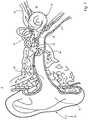
1 ein teilweise geschnitten dargestelltes, menschliches Ohr;2 ein in das Ohr aus1 eingesetztes Hörhilfe-System mit Hörhilfe und Versorgungsmodul;3 das Hörhilfe-System aus2 in schematischer Seitendarstellung;4 eine vergrößerte und schematische Darstellung der Hörhilfe aus3 ; und5 eine vergrößerte Darstellung der Blendscheibe in der Hörhilfe aus4 .
1 a partially cut illustrated human ear;2 one in the ear1 inserted hearing aid system with hearing aid and supply module;3 the hearing aid system2 in schematic page presentation;4 an enlarged and schematic representation of the hearing aid3 ; and5 an enlarged view of the aperture in the hearing aid4 ,
In
Die Cochlea
Wenn das ovale Fenster
Das menschliche Ohr
Ein Druck der Gehörknöchelchen
Das erfindungsgemäße Hörhilfe-System
Während das Versorgungsmodul
Das Versorgungsmodul
Üblicherweise gelangt der Schall von außen in die Ohrmuschel, wird über den Gehörgang
Bei dem in
An der Hörhilfe
Die optoelektronischen Sensoren
In dem Versorgungsmodul
Die Hörhilfe
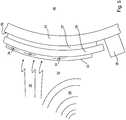
In
Der Aktor
Aktor
Der Aktor
Der Piezo-Scheibenaktor kann eine segmentierte oder eine nicht segmentierte Membranstruktur
Ein derartiger Piezo-Scheibenaktor ist prinzipiell aus der eingangs genannten
Verglichen mit der Membranstruktur
Die Blendscheibe
Die Mikrophoneinheit
Dazu können als Sensoren
Claims (19)
Translated fromGermanPriority Applications (8)
| Application Number | Priority Date | Filing Date | Title |
|---|---|---|---|
| DE102013114771.2ADE102013114771B4 (en) | 2013-12-23 | 2013-12-23 | In the auditory canal einbringbare hearing aid and hearing aid system |
| CA2934915ACA2934915C (en) | 2013-12-23 | 2014-12-18 | Hearing aid that can be inserted into the ear canal and hearing aid system |
| ES14815354TES2769599T3 (en) | 2013-12-23 | 2014-12-18 | Hearing aid that can be inserted into the ear canal and hearing aid system |
| EP14815354.7AEP3087761B1 (en) | 2013-12-23 | 2014-12-18 | Hearing aid that can be introduced into the auditory canal and hearing aid system |
| DK14815354.7TDK3087761T3 (en) | 2013-12-23 | 2014-12-18 | HEARING WHICH CAN BE INSERTED IN THE EARRING AND HEARING SYSTEM |
| US15/107,888US10219087B2 (en) | 2013-12-23 | 2014-12-18 | Hearing aid that can be introduced into the auditory canal and hearing aid system |
| PCT/EP2014/078440WO2015097056A1 (en) | 2013-12-23 | 2014-12-18 | Hearing aid that can be introduced into the auditory canal and hearing aid system |
| US16/250,885US10616699B2 (en) | 2013-12-23 | 2019-01-17 | Hearing aid that can be introduced into the auditory canal and hearing aid system |
Applications Claiming Priority (1)
| Application Number | Priority Date | Filing Date | Title |
|---|---|---|---|
| DE102013114771.2ADE102013114771B4 (en) | 2013-12-23 | 2013-12-23 | In the auditory canal einbringbare hearing aid and hearing aid system |
Publications (2)
| Publication Number | Publication Date |
|---|---|
| DE102013114771A1 DE102013114771A1 (en) | 2015-06-25 |
| DE102013114771B4true DE102013114771B4 (en) | 2018-06-28 |
Family
ID=52130260
Family Applications (1)
| Application Number | Title | Priority Date | Filing Date |
|---|---|---|---|
| DE102013114771.2AActiveDE102013114771B4 (en) | 2013-12-23 | 2013-12-23 | In the auditory canal einbringbare hearing aid and hearing aid system |
Country Status (7)
| Country | Link |
|---|---|
| US (2) | US10219087B2 (en) |
| EP (1) | EP3087761B1 (en) |
| CA (1) | CA2934915C (en) |
| DE (1) | DE102013114771B4 (en) |
| DK (1) | DK3087761T3 (en) |
| ES (1) | ES2769599T3 (en) |
| WO (1) | WO2015097056A1 (en) |
Families Citing this family (16)
| Publication number | Priority date | Publication date | Assignee | Title |
|---|---|---|---|---|
| US8401212B2 (en) | 2007-10-12 | 2013-03-19 | Earlens Corporation | Multifunction system and method for integrated hearing and communication with noise cancellation and feedback management |
| EP2656639B1 (en) | 2010-12-20 | 2020-05-13 | Earlens Corporation | Anatomically customized ear canal hearing apparatus |
| US10034103B2 (en) | 2014-03-18 | 2018-07-24 | Earlens Corporation | High fidelity and reduced feedback contact hearing apparatus and methods |
| DK3169396T3 (en) | 2014-07-14 | 2021-06-28 | Earlens Corp | Sliding bias and peak limitation for optical hearing aids |
| US9924276B2 (en) | 2014-11-26 | 2018-03-20 | Earlens Corporation | Adjustable venting for hearing instruments |
| US10178483B2 (en) | 2015-12-30 | 2019-01-08 | Earlens Corporation | Light based hearing systems, apparatus, and methods |
| US11350226B2 (en) | 2015-12-30 | 2022-05-31 | Earlens Corporation | Charging protocol for rechargeable hearing systems |
| EP3510796A4 (en)* | 2016-09-09 | 2020-04-29 | Earlens Corporation | Contact hearing systems, apparatus and methods |
| WO2018093733A1 (en) | 2016-11-15 | 2018-05-24 | Earlens Corporation | Improved impression procedure |
| US20190387334A1 (en)* | 2017-01-20 | 2019-12-19 | Massachusetts Eye And Ear Infirmary | Coupler Device for Round Window Stimulation of the Cochlea |
| WO2019173470A1 (en) | 2018-03-07 | 2019-09-12 | Earlens Corporation | Contact hearing device and retention structure materials |
| WO2019199680A1 (en) | 2018-04-09 | 2019-10-17 | Earlens Corporation | Dynamic filter |
| DE102018207922A1 (en)* | 2018-05-18 | 2019-11-21 | Vibrosonic Gmbh | Multi-part eardrum contact hearing aid placed deep in the ear canal |
| DE102018207918A1 (en)* | 2018-05-18 | 2019-11-21 | Vibrosonic Gmbh | A method of charging an ear canal-mounted electrical device, electrical device, charging module and hearing system |
| DE102019201273A1 (en)* | 2019-01-31 | 2020-08-06 | Vibrosonic Gmbh | Vibration module for laying on an eardrum |
| US10880654B1 (en) | 2019-08-14 | 2020-12-29 | Soniphi Llc | Systems and methods for expanding sensation using temperature variations |
Citations (11)
| Publication number | Priority date | Publication date | Assignee | Title |
|---|---|---|---|---|
| DE2044870A1 (en) | 1970-09-10 | 1972-03-16 | Matutinovic T | Device and method for transmitting acoustic signals |
| US5259032A (en) | 1990-11-07 | 1993-11-02 | Resound Corporation | contact transducer assembly for hearing devices |
| DE3788529T2 (en) | 1986-03-07 | 1994-06-16 | Smith & Nephew Richards Inc | Magnetic induction hearing aid. |
| DE69204555T2 (en) | 1991-06-07 | 1996-05-02 | Philips Electronics N.V., Eindhoven | Hearing aid for attachment in the ear canal. |
| EP0696907B1 (en) | 1993-05-03 | 2002-03-06 | Alan Y. Chow | Independent photoelectric artificial retina device |
| DE19705988C2 (en) | 1996-10-23 | 2002-04-11 | Univ Eberhard Karls | Retinal implant |
| DE10154390A1 (en) | 2001-05-08 | 2002-12-05 | Vossieck Gmbh Dr | Hearing aid with venting |
| US20100152527A1 (en) | 2008-12-16 | 2010-06-17 | Ear Lens Corporation | Hearing-aid transducer having an engineered surface |
| EP1470737B1 (en) | 2002-01-24 | 2010-09-15 | Sentient Medical Ltd, | Hearing aid |
| US7867160B2 (en) | 2004-10-12 | 2011-01-11 | Earlens Corporation | Systems and methods for photo-mechanical hearing transduction |
| EP2362686A2 (en) | 2010-02-26 | 2011-08-31 | Fraunhofer-Gesellschaft zur Förderung der angewandten Forschung | Sound converter for installation in an ear |
Family Cites Families (2)
| Publication number | Priority date | Publication date | Assignee | Title |
|---|---|---|---|---|
| BRPI0919266A2 (en)* | 2008-09-22 | 2017-05-30 | SoundBeam LLC | device and method for transmitting an audio signal to a user, methods for manufacturing a device for transmitting an audio signal to the user, and for providing an audio device for a user, and device and method for transmitting a sound for a user. user having a tympanic membrane |
| AT511680B1 (en) | 2011-06-24 | 2015-02-15 | Rafael Kubisz | SPEAKER SYSTEM |
- 2013
- 2013-12-23DEDE102013114771.2Apatent/DE102013114771B4/enactiveActive
- 2014
- 2014-12-18USUS15/107,888patent/US10219087B2/enactiveActive
- 2014-12-18ESES14815354Tpatent/ES2769599T3/enactiveActive
- 2014-12-18DKDK14815354.7Tpatent/DK3087761T3/enactive
- 2014-12-18WOPCT/EP2014/078440patent/WO2015097056A1/enactiveApplication Filing
- 2014-12-18EPEP14815354.7Apatent/EP3087761B1/enactiveActive
- 2014-12-18CACA2934915Apatent/CA2934915C/enactiveActive
- 2019
- 2019-01-17USUS16/250,885patent/US10616699B2/enactiveActive
Patent Citations (11)
| Publication number | Priority date | Publication date | Assignee | Title |
|---|---|---|---|---|
| DE2044870A1 (en) | 1970-09-10 | 1972-03-16 | Matutinovic T | Device and method for transmitting acoustic signals |
| DE3788529T2 (en) | 1986-03-07 | 1994-06-16 | Smith & Nephew Richards Inc | Magnetic induction hearing aid. |
| US5259032A (en) | 1990-11-07 | 1993-11-02 | Resound Corporation | contact transducer assembly for hearing devices |
| DE69204555T2 (en) | 1991-06-07 | 1996-05-02 | Philips Electronics N.V., Eindhoven | Hearing aid for attachment in the ear canal. |
| EP0696907B1 (en) | 1993-05-03 | 2002-03-06 | Alan Y. Chow | Independent photoelectric artificial retina device |
| DE19705988C2 (en) | 1996-10-23 | 2002-04-11 | Univ Eberhard Karls | Retinal implant |
| DE10154390A1 (en) | 2001-05-08 | 2002-12-05 | Vossieck Gmbh Dr | Hearing aid with venting |
| EP1470737B1 (en) | 2002-01-24 | 2010-09-15 | Sentient Medical Ltd, | Hearing aid |
| US7867160B2 (en) | 2004-10-12 | 2011-01-11 | Earlens Corporation | Systems and methods for photo-mechanical hearing transduction |
| US20100152527A1 (en) | 2008-12-16 | 2010-06-17 | Ear Lens Corporation | Hearing-aid transducer having an engineered surface |
| EP2362686A2 (en) | 2010-02-26 | 2011-08-31 | Fraunhofer-Gesellschaft zur Förderung der angewandten Forschung | Sound converter for installation in an ear |
Non-Patent Citations (4)
| Title |
|---|
| „Aktive elektronische Hörimplantate für Mittel- und Innenohrschwerhörige - eine neue Ära der Ohrchirurgie" von H.P. Zenner und H. Leysieffer (erschienen in HNO, Ausgabe 10/97, Seite 749 - 774, Springer Verlag) |
| „Concept and evaluation of an endaurally insertable middle-ear implant" in Med Eng Phys 35 (103), 532-536 35 |
| Haynes et al., „Middle ear implantable hearing devices: an overview" in Trends Amplif. 13 (2009), 206-214 |
| Perkins et al., „The EarLens system: new sound transduction methods", Hear. Res., 263 (2010), 104-113 |
Also Published As
| Publication number | Publication date |
|---|---|
| DE102013114771A1 (en) | 2015-06-25 |
| CA2934915C (en) | 2021-08-31 |
| WO2015097056A1 (en) | 2015-07-02 |
| EP3087761A1 (en) | 2016-11-02 |
| EP3087761B1 (en) | 2019-11-13 |
| US20190158966A1 (en) | 2019-05-23 |
| US10219087B2 (en) | 2019-02-26 |
| CA2934915A1 (en) | 2015-07-02 |
| US20160323680A1 (en) | 2016-11-03 |
| DK3087761T3 (en) | 2020-01-20 |
| US10616699B2 (en) | 2020-04-07 |
| ES2769599T3 (en) | 2020-06-26 |
Similar Documents
| Publication | Publication Date | Title |
|---|---|---|
| DE102013114771B4 (en) | In the auditory canal einbringbare hearing aid and hearing aid system | |
| EP1173044B1 (en) | Implantable system for the rehabilitation of a hearing disorder | |
| DE10018361C2 (en) | At least partially implantable cochlear implant system for the rehabilitation of a hearing disorder | |
| DE19882589B3 (en) | Transducer with piezoelectric film | |
| EP1191815B1 (en) | At least partially implantable hearing system with direct mechanical stimulation of a lymphatic space of the internal ear | |
| US5707338A (en) | Stapes vibrator | |
| EP1145734B1 (en) | At least partially implantable system for the rehabilitation of a hearing disorder | |
| US5360388A (en) | Round window electromagnetic implantable hearing aid | |
| US5997466A (en) | Implantable hearing system having multiple transducers | |
| US5762583A (en) | Piezoelectric film transducer | |
| US20100048983A1 (en) | Multipath Stimulation Hearing Systems | |
| US10639474B2 (en) | Hearing aid system and a method of operating thereof | |
| US20090292161A1 (en) | Multi-mode hearing prosthesis | |
| WO1999008476A2 (en) | Implantable hearing system having multiple transducers | |
| EP1181950A2 (en) | Implantable hearing system having means for measuring the coupling quality | |
| EP1145733A2 (en) | At least partially implantable system for the rehabilitation of a hearing disorder | |
| AU2017327850B2 (en) | Passive middle ear prosthesis | |
| DE102009051713A1 (en) | Electro-mechanical converter | |
| DE10030372A1 (en) | Implantable hydroacoustic transducer, comprises a hollow section with a flexible tube connected to it, a membrane, and a liquid filling | |
| Ashmore | Mechanics of hearing | |
| DE102007031114B4 (en) | Hearing implant with multidirectional acting actuator |
Legal Events
| Date | Code | Title | Description |
|---|---|---|---|
| R012 | Request for examination validly filed | ||
| R016 | Response to examination communication | ||
| R018 | Grant decision by examination section/examining division | ||
| R020 | Patent grant now final |