DE102013113633A1 - Radiometric measuring arrangement - Google Patents
Radiometric measuring arrangementDownload PDFInfo
- Publication number
- DE102013113633A1 DE102013113633A1DE102013113633.8ADE102013113633ADE102013113633A1DE 102013113633 A1DE102013113633 A1DE 102013113633A1DE 102013113633 ADE102013113633 ADE 102013113633ADE 102013113633 A1DE102013113633 A1DE 102013113633A1
- Authority
- DE
- Germany
- Prior art keywords
- measuring arrangement
- scintillator
- temperature
- resonant circuit
- interruption
- Prior art date
- Legal status (The legal status is an assumption and is not a legal conclusion. Google has not performed a legal analysis and makes no representation as to the accuracy of the status listed.)
- Ceased
Links
- 238000001514detection methodMethods0.000claimsabstractdescription23
- 238000012806monitoring deviceMethods0.000claimsabstractdescription23
- 238000012545processingMethods0.000claimsabstractdescription5
- 230000005540biological transmissionEffects0.000claimsdescription26
- 230000001960triggered effectEffects0.000claimsdescription10
- 238000006243chemical reactionMethods0.000claims1
- 230000005855radiationEffects0.000description13
- 239000003990capacitorSubstances0.000description12
- 239000000463materialSubstances0.000description10
- 238000005259measurementMethods0.000description6
- 238000012544monitoring processMethods0.000description5
- 230000005284excitationEffects0.000description4
- 239000004793PolystyreneSubstances0.000description2
- 230000001419dependent effectEffects0.000description2
- 238000011161developmentMethods0.000description2
- 230000018109developmental processEffects0.000description2
- 238000010586diagramMethods0.000description2
- 238000012423maintenanceMethods0.000description2
- 238000000034methodMethods0.000description2
- 229920002223polystyrenePolymers0.000description2
- 230000002285radioactive effectEffects0.000description2
- 230000032683agingEffects0.000description1
- 239000011248coating agentSubstances0.000description1
- 238000000576coating methodMethods0.000description1
- 238000010276constructionMethods0.000description1
- 230000000694effectsEffects0.000description1
- -1for exampleSubstances0.000description1
- 230000002427irreversible effectEffects0.000description1
- 230000007257malfunctionEffects0.000description1
- 238000000691measurement methodMethods0.000description1
- 238000002844meltingMethods0.000description1
- 230000008018meltingEffects0.000description1
- 230000010355oscillationEffects0.000description1
- 230000003534oscillatory effectEffects0.000description1
- 230000001681protective effectEffects0.000description1
- 239000007787solidSubstances0.000description1
- 238000012360testing methodMethods0.000description1
- 238000012546transferMethods0.000description1
- 230000000007visual effectEffects0.000description1
Images


Classifications
- G—PHYSICS
- G01—MEASURING; TESTING
- G01T—MEASUREMENT OF NUCLEAR OR X-RADIATION
- G01T1/00—Measuring X-radiation, gamma radiation, corpuscular radiation, or cosmic radiation
- G01T1/16—Measuring radiation intensity
- G01T1/20—Measuring radiation intensity with scintillation detectors
- G01T1/208—Circuits specially adapted for scintillation detectors, e.g. for the photo-multiplier section
- G—PHYSICS
- G01—MEASURING; TESTING
- G01F—MEASURING VOLUME, VOLUME FLOW, MASS FLOW OR LIQUID LEVEL; METERING BY VOLUME
- G01F23/00—Indicating or measuring liquid level or level of fluent solid material, e.g. indicating in terms of volume or indicating by means of an alarm
- G01F23/22—Indicating or measuring liquid level or level of fluent solid material, e.g. indicating in terms of volume or indicating by means of an alarm by measuring physical variables, other than linear dimensions, pressure or weight, dependent on the level to be measured, e.g. by difference of heat transfer of steam or water
- G01F23/28—Indicating or measuring liquid level or level of fluent solid material, e.g. indicating in terms of volume or indicating by means of an alarm by measuring physical variables, other than linear dimensions, pressure or weight, dependent on the level to be measured, e.g. by difference of heat transfer of steam or water by measuring the variations of parameters of electromagnetic or acoustic waves applied directly to the liquid or fluent solid material
- G01F23/284—Electromagnetic waves
- G01F23/288—X-rays; Gamma rays or other forms of ionising radiation
- G—PHYSICS
- G01—MEASURING; TESTING
- G01F—MEASURING VOLUME, VOLUME FLOW, MASS FLOW OR LIQUID LEVEL; METERING BY VOLUME
- G01F25/00—Testing or calibration of apparatus for measuring volume, volume flow or liquid level or for metering by volume
- G01F25/20—Testing or calibration of apparatus for measuring volume, volume flow or liquid level or for metering by volume of apparatus for measuring liquid level
- G01F25/24—Testing proper functioning of electronic circuits
Landscapes
- Physics & Mathematics (AREA)
- General Physics & Mathematics (AREA)
- Electromagnetism (AREA)
- Fluid Mechanics (AREA)
- Thermal Sciences (AREA)
- Health & Medical Sciences (AREA)
- Life Sciences & Earth Sciences (AREA)
- High Energy & Nuclear Physics (AREA)
- Molecular Biology (AREA)
- Spectroscopy & Molecular Physics (AREA)
- Measurement Of Radiation (AREA)
Abstract
Translated fromGermanDescription
Translated fromGermanDie vorliegende Erfindung betrifft eine radiometrische Messanordnung gemäß dem Oberbegriff des Patentanspruchs 1.The present invention relates to a radiometric measuring arrangement according to the preamble of patent claim 1.
Aus dem Stand der Technik sind verschiedene radiometrische Messanordnungen zur Füllstand-, Dichte- und Grenzstandmessung bekannt, wobei zur Messung eine radioaktive Strahlenquelle und eine Erfassungseinrichtung an gegenüberliegenden Seiten eines zu überwachenden Behälters angeordnet werden. Von der radioaktiven Strahlenquelle wird Gammastrahlung durch den Behälter in Richtung der Erfassungseinrichtung ausgesendet und auf ihrem Weg durch das Füllgut je nach Füllstand und Dichte des Füllgutes mehr oder weniger absorbiert. Auf Basis der von der Erfassungseinrichtung detektierten Strahlungsstärke kann dann ein Rückschluss auf den Füllstand oder die Dichte eines zwischen der Strahlenquelle und der Erfassungseinrichtung befindlichen Füllgutes gezogen werden. Ebenso ist eine Grenzstanderfassung möglich.Various radiometric measuring arrangements for level, density and level measurement are known from the prior art, wherein a radioactive radiation source and a detection device are arranged on opposite sides of a container to be monitored for the purpose of measurement. From the radioactive source of radiation gamma radiation is emitted through the container in the direction of the detection device and more or less absorbed on their way through the contents depending on the level and density of the contents. On the basis of the radiation intensity detected by the detection device, it is then possible to draw a conclusion on the fill level or the density of a filling material located between the radiation source and the detection device. Likewise, a level detection is possible.
Beispielsweise bei der Füllstandmessung ist eine von der Erfassungseinrichtung erfasste Strahlungsstärke indirekt proportional zu einem Füllstand in dem Behälter, so dass eine Füllstandmessung hoher Güte möglich ist.For example, in the level measurement, a radiation intensity detected by the detection device is indirectly proportional to a level in the container, so that a level measurement of high quality is possible.
Ein besonderer Vorteil der radiometrischen Füllstandmessung ist, dass die für die Messung notwendigen Komponenten, nämlich die Strahlenquelle und die Erfassungseinrichtung, außerhalb eines Behälters anordenbar sind und damit weder die Prozessbedingungen innerhalb des Behälters noch die Eigenschaften des Füllgutes Auswirkungen auf die Einsetzbarkeit dieser Messmethode haben.A particular advantage of the radiometric level measurement is that the components required for the measurement, namely the radiation source and the detection device, can be arranged outside a container and thus neither the process conditions within the container nor the properties of the contents have any effect on the applicability of this measurement method.
Bei den aus dem Stand der Technik bekannten radiometrischen Messanordnungen ist es bekannt, dass die Erfassungseinrichtung als Szintillator mit einem nachgeschalteten Photomultiplier ausgestaltet ist. Die auf das Szintillatormaterial treffende Gammastrahlung regt dieses durch Stoßprozesse an, wobei das Szintillatormaterial unter Abgabe von Licht in seinen Ausgangszustand zurückkehrt. Durch eine Messung der Lichtmenge, die beispielsweise über einen Photomultiplier und eine nachgeschaltete Elektronik erfolgt, kann dann auf die Intensität der eintreffenden Strahlung und somit wie oben angegeben beispielsweise auf einen Füllstand innerhalb des Behälters geschlossen werden. Insbesondere organische Szintillatormaterialien, beispielsweise polymere Festkörper, sind jedoch äußerst temperaturempfindlich und dürfen daher nicht oberhalb einer bestimmten Grenztemperatur gelagert oder betrieben werden. Bei Polystyren als Szintillatormaterial liegt diese Grenztemperatur beispielsweise bei +50° C.In the known from the prior art radiometric measuring arrangements, it is known that the detection device is designed as a scintillator with a downstream photomultiplier. The gamma radiation impinging on the scintillator material stimulates it by impact processes, with the scintillator material returning to its initial state with the emission of light. By measuring the amount of light, which takes place for example via a photomultiplier and a downstream electronics, can then be closed, for example, to a level within the container on the intensity of the incident radiation and thus, as indicated above. In particular, organic scintillator materials, such as polymeric solids, however, are extremely sensitive to temperature and therefore may not be stored or operated above a certain limit temperature. In the case of polystyrene as scintillator material, this limit temperature is, for example, + 50 ° C.
Aus dem Stand der Technik ist es daher bekannt, die Einhaltung dieser Grenztemperatur durch sog. Temperaturmessstreifen zu überwachen. Wird beispielsweise ein schlauchförmig ausgebildeter Szintillator mit der Länge von beispielsweise 5 m verwendet, so werden solche Temperaturmessstreifen verteilt über die Länge, beispielsweise mit einem Abstand von jeweils 50 cm, auf den Szintillator aufgebracht. Problematisch hierbei ist, dass die verwendeten Temperaturmessstreifen einem Alterungsprozess unterliegen und daher nach einer Verwendungsdauer von max. 18 Monaten ausgetauscht werden müssen. Dies bedingt einen hohen Wartungsaufwand, der als nachteilig empfunden wird, so dass ein Austausch der Temperaturteststreifen dann häufig nicht oder zumindest nicht regelmäßig durchgeführt wird.From the prior art, it is therefore known to monitor compliance with this limit temperature by so-called. Temperature gauges. If, for example, a tube-shaped scintillator with a length of, for example, 5 m is used, then such temperature measuring strips are distributed over the length, for example at a distance of 50 cm, applied to the scintillator. The problem here is that the temperature measuring strips used are subject to aging and therefore after a period of use of max. 18 months to be replaced. This requires a high maintenance, which is perceived as disadvantageous, so that a replacement of the temperature test strips is then often not or at least not regularly performed.
Da die Funktionsfähigkeit des Szintillators auch maßgeblich davon abhängt, dass dieser die Grenztemperatur nicht überschritten hat, können durch eine Temperaturüberschreitung bedingte Fehlfunktionen nicht identifiziert werden und es müssen zusätzliche Überprüfungen der gesamten Messanordnung durchgeführt werden. Dies wird ebenfalls als nachteilig empfunden.Since the scintillator's ability to function also depends to a considerable extent on the fact that it has not exceeded the limit temperature, malfunction caused by a temperature exceeding can not be identified and additional checks of the entire measuring arrangement must be carried out. This is also felt to be disadvantageous.
Es ist die Aufgabe der vorliegenden Erfindung eine radiometrische Messanordnung, wie sie aus dem Stand der Technik bekannt ist, derart weiterzubilden, dass der im Stand der Technik notwendige Wartungsaufwand verringert und die Messsicherheit erhöht wird.It is the object of the present invention to develop a radiometric measuring arrangement, as known from the prior art, in such a way that the maintenance expenditure required in the prior art is reduced and the measuring reliability is increased.
Diese Aufgabe wird durch eine radiometrische Messanordnung mit den Merkmalen des Patentanspruchs 1 gelöst. Vorteilhafte Weiterbildungen dieser Messanordnung sind in den abhängigen Patentansprüchen wiedergegeben.This object is achieved by a radiometric measuring arrangement having the features of patent claim 1. Advantageous developments of this measuring arrangement are given in the dependent claims.
Eine erfindungsgemäße radiometrische Messanordnung weist wenigstens eine Erfassungseinrichtung mit einem bevorzugt langgestreckten Szintillator, einem Photomultiplier zur Umwandlung von in dem Szintillator erzeugten Lichtblitzen in elektrische Signale und eine Messelektronik zur Verarbeitung der elektrischen Signale mit einer Temperaturüberwachungseinrichtung für den Szintillator auf, wobei die Erfassungseinrichtung wenigstens eine Unterbrechungseinrichtung als Teil der Temperaturüberwachungseinrichtung aufweist, die eine elektrische Verbindung bei Überschreiten einer vorgegebenen Grenztemperatur unterbricht.A radiometric measuring arrangement according to the invention has at least one detection device with a preferably elongated scintillator, a photomultiplier for converting light flashes generated in the scintillator into electrical signals, and measuring electronics for processing the electrical signals with a temperature monitoring device for the scintillator, wherein the detection device comprises at least one interruption device Part of the temperature monitoring device which interrupts an electrical connection when a predetermined limit temperature is exceeded.
Durch eine derartige Anordnung kann auf die im Stand der Technik verwendeten Temperaturmessstreifen verzichtet und gleichzeitig eine elektronische Überprüfung eines Überschreitens der vorgegebenen Grenztemperatur durchgeführt werden. Es kann auf diese Weise außerdem erreicht werden, dass eine visuelle Kontrolle der einzelnen Temperaturüberwachungseinrichtungen (Temperaturmessstreifen) unterbleiben und somit eine automatische Überwachung erreicht werden kann.Such an arrangement makes it possible to dispense with the temperature measuring strips used in the prior art and at the same time an electronic check of exceeding the predetermined limit temperature can be performed. It can also be achieved this way that a visual control of the individual temperature monitoring devices (temperature measuring strips) is omitted and thus an automatic monitoring can be achieved.
Eine besonders einfache Ausgestaltung einer solchen Temperaturüberwachungseinrichtung wird erreicht, wenn die Unterbrechungseinrichtung als wenigstens eine Temperatursicherung ausgebildet ist.A particularly simple embodiment of such a temperature monitoring device is achieved when the interruption device is designed as at least one thermal fuse.
Temperatursicherungen sind auf dem freien Markt für verschiedene Grenztemperaturen verfügbar, so dass eine optimale Anpassung an eine für das jeweilige Szintillatormaterial geltende Grenztemperatur erfolgen kann.Thermal fuses are available on the open market for various limiting temperatures so that they can be optimally adapted to a limit temperature applicable to the particular scintillator material.
Als Temperatursicherung wird vorliegend ein in einem elektrischen Stromkreis einsetzbares Bauteil verstanden, bei dem ein durch ein temperatursensitives Material geschlossener Stromkreis bei Überschreiten einer Grenztemperatur beispielsweise durch Federkraft geöffnet wird. Als temperatursensitives Material können beispielsweise Materialien mit einem bestimmten Schmelzpunkt zum Einsatz kommen. Ein wesentliches Merkmal solcher Temperatursicherungen ist, dass eine Unterbrechung des Stromkreises irreversibel erfolgt, so dass anders als beispielsweise beim Einsatz von Bimetallelementen bei einem Überschreiten der Grenztemperatur der Stromkreis durch ein nachfolgendes Unterschreiten der Grenztemperatur nicht wieder geschlossen wird.In the present case, a thermal fuse is understood to mean a component which can be used in an electrical circuit, in which a circuit closed by a temperature-sensitive material is opened when a limit temperature is exceeded, for example by spring force. As a temperature-sensitive material, for example, materials with a certain melting point can be used. An essential feature of such thermal fuses is that an interruption of the circuit is irreversible, so that unlike, for example, when using bimetallic elements at an exceeding of the limit temperature of the circuit is not closed again by a subsequent below the limit temperature.
Eine Befestigung der Temperaturüberwachungseinrichtung
Eine besonders einfache Überwachung kann bevorzugt bei langgestreckten Szintillatoren, die beispielsweise eine Länge von bis zu 10 Metern, bevorzugt von 3 bis 6 Metern, aufweisen, erreicht werden, wenn die Unterbrechungseinrichtung aus einer Reihenschaltung einer Mehrzahl von Temperatursicherungen gebildet ist. Es können hierzu wenigstens zwei, bevorzugt wenigstens vier oder beispielsweise zehn Temperatursicherungen in Reihe geschaltet und über die Länge des Szintillators verteilt angeordnet werden, so dass auch ein abschnittsweises Überschreiten der Grenztemperatur detektiert werden kann. Die Detektion kann dann beispielsweise dadurch erfolgen, dass der elektrische Durchgang der Anordnung leitungsgebunden, beispielsweise mit einem Ohmmeter, geprüft wird.A particularly simple monitoring can preferably be achieved with elongate scintillators, which for example have a length of up to 10 meters, preferably of 3 to 6 meters, when the interruption device is formed from a series connection of a plurality of temperature fuses. For this purpose, at least two, preferably at least four or, for example, ten temperature fuses can be connected in series and distributed over the length of the scintillator, so that a section-wise exceeding of the limit temperature can also be detected. The detection can then take place, for example, in that the electrical continuity of the arrangement is conducted on a line, for example with an ohmmeter.
Bevorzugt ist die Unterbrechungseinrichtung mit einer Übertragungseinheit gekoppelt. Durch eine an die Unterbrechungseinrichtung gekoppelte Übertragungseinheit kann erreicht werden, dass, ggfs. auch ohne eine Reihenschaltung verschiedener Elemente zu verwenden, an unterschiedlichen Positionen des Szintillators eine Temperaturüberwachung stattfinden kann. Die Übertragungseinheit kann dabei bevorzugt drahtlos ausgebildet sein, so dass auf zusätzliche Signalleitungen innerhalb oder entlang des Szintillators verzichtet werden kann.Preferably, the interruption device is coupled to a transmission unit. By means of a transmission unit coupled to the interruption device, it can be achieved that, if necessary, even without a series connection of different elements, temperature monitoring can take place at different positions of the scintillator. The transmission unit may preferably be designed wirelessly, so that it is possible to dispense with additional signal lines within or along the scintillator.
In einer Ausgestaltungsform ist die Übertragungseinheit als Schwingkreis ausgebildet. Ein solcher Schwingkreis kann kabelgebunden oder kabellos zu einer Schwingung angeregt werden, wobei bevorzugt die Unterbrechungseinrichtung mit dem Schwingkreis derart verschaltet ist, dass der Schwingkreis abhängig davon, ob die Unterbrechungseinrichtung ausgelöst hat oder nicht, eine unterschiedliche Resonanzfrequenz aufweist, die detektiert und weiter verarbeitet werden kann.In one embodiment, the transmission unit is designed as a resonant circuit. Such a resonant circuit can be wired or wirelessly excited to a vibration, wherein preferably the interruption device is connected to the resonant circuit such that the resonant circuit depending on whether the interruption device has triggered or not, a different resonant frequency, which can be detected and further processed ,
In einer weiteren Ausgestaltungsform ist die Übertragungseinheit als eine RFID-Übertragungseinrichtung ausgebildet, wobei die Unterbrechungseinrichtung bevorzugt mit der RFID-Übertragungseinrichtung derart verschaltet ist, dass eine Sendeantenne, bevorzugt eine als Sendeantenne wirkende Spule von der RFID-Übertragungseinrichtung abgekoppelt oder kurzgeschlossen ist, wenn die Unterbrechungseinrichtung ausgelöst hat.In a further embodiment, the transmission unit is designed as an RFID transmission device, wherein the interruption device is preferably connected to the RFID transmission device such that a transmitting antenna, preferably a coil acting as a transmitting antenna, is decoupled from the RFID transmission device or short-circuited if the interruption device has triggered.
In einer Weiterbildung kann die Unterbrechungseinrichtung mit dem Schwingkreis derart verschaltet sein, dass der Schwingkreis bei unausgelöster Unterbrechungseinrichtung bei einer anderen Frequenz schwingt als wenn die Unterbrechungseinrichtung ausgelöst hat. Eine solche Veränderung einer Resonanzfrequenz des Schwingkreises kann beispielsweise dadurch erreicht werden, dass eine Spule des Schwingkreises, die als Induktivität wirkt, bei unausgelöster Unterbrechungseinrichtung teilweise überbrückt ist und durch ein Auslösen der Unterbrechungseinrichtung in ihrem wirksamen Wert verändert wird.In a further development, the interruption device can be connected to the resonant circuit in such a way that the resonant circuit oscillates at an unreleased interruption device at a different frequency than when the interruption device has triggered. Such a change in a resonant frequency of the resonant circuit can be achieved, for example, in that a coil of the resonant circuit, which acts as an inductance, is partially bridged in the case of an untripped interruption device and is changed to its effective value by triggering the interruption device.
Eine weitere Möglichkeit zur Veränderung der Resonanzfrequenz eines Schwingkreises liegt beispielsweise darin, den Schwingkreis mit einer Parallelschaltung aus einem ersten Kondensator und einem zweiten Kondensator aufzubauen, wobei der zweite Kondensator bei einem Auslösen der Unterbrechungseinrichtung von der Parallelschaltung getrennt und auf diese Weise die im Schwingkreis wirkende Kapazität und damit dessen Resonanzfrequenz ebenfalls verändert wird.Another possibility for changing the resonant frequency of a resonant circuit is, for example, to construct the resonant circuit with a parallel circuit of a first capacitor and a second capacitor, wherein the second capacitor disconnected from the parallel circuit in a triggering of the interruption device and in this way the capacity acting in the resonant circuit and thus its resonant frequency is also changed.
Bevorzugt kann eine Mehrzahl von Temperatursicherungen über die Länge des Szintillators verteilt angeordnet sein, so dass auch ein lokales Überschreiten der Grenztemperatur erfassbar ist.Preferably, a plurality of temperature fuses can be distributed over the length of the scintillator, so that a local exceeding of the limit temperature can be detected.
Die einzelnen Temperatursicherungen können dabei entweder jeweils einzeln oder wie bereits dargelegt in Reihe geschaltet mit einer bzw. der Übertragungseinheit verschaltet sein. Die Verwendung mehrerer separater Übertragungseinheiten hat den Vorteil, dass auf diese Weise eindeutig identifizierbar ist, an welcher Stelle der Szintillator lokal die Grenztemperatur überschritten hat und zusätzlich auf entsprechende Signalleitungen zur Verschaltung der Unterbrechungseinrichtungen verzichtet werden kann.The individual thermal fuses can either individually or as already stated connected in series with one or the Be connected transfer unit. The use of a plurality of separate transmission units has the advantage that in this way it can be clearly identified at which point the scintillator has locally exceeded the limit temperature and, in addition, corresponding signal lines for interconnecting the interruption devices can be dispensed with.
Bevorzugt weist die Temperaturüberwachungseinrichtung außerdem eine Abfragevorrichtung auf. Die Abfragevorrichtung kann dabei beispielsweise zum Abfragen einer RFID-Übertragungseinheit oder zum Anregen eines Schwingkreises und zum Detektieren eines Ausschwingens des Schwingkreises ausgebildet sein. Bevorzugt ist die Abfragevorrichtung dementsprechend drahtlos ausgebildet, so dass sie den oder die Schwingkreise durch Aussenden eines elektromagnetischen Signals in einer bestimmten Frequenz zu einer Schwingung anregt und dann bevorzugt eine resultierende Schwingung des Schwingkreises bzw. deren Frequenz detektiert.The temperature monitoring device preferably also has an interrogation device. The interrogation device can be designed, for example, to interrogate an RFID transmission unit or to excite a resonant circuit and to detect a swinging out of the resonant circuit. Accordingly, the interrogation device is accordingly designed to be wireless, so that it excites the oscillating circuit (s) by emitting an electromagnetic signal in a specific frequency to a vibration and then preferably detects a resulting oscillation of the oscillatory circuit or its frequency.
Erfindungsgemäß ist außerdem die Verwendung einer Mehrzahl von Temperatursicherungen in einer radiometrischen Messanordnung mit einer Erfassungseinrichtung mit einem langgestreckten Szintillator, einem Photomultiplier zur Umwandlung von in dem Szintillator erzeugten Lichtblitzen in elektrische Signale und einer Messelektronik zur Verarbeitung der elektrischen Signale als Bestandteil einer Temperaturüberwachungseinrichtung für den Szintillator. Eine derartige Verwendung von Temperatursicherungen ist bislang aus dem Stand der Technik nicht bekannt und weist ebenfalls die oben im Zusammenhang mit der Messanordnung beschriebenen Vorteile auf.The invention also relates to the use of a plurality of temperature fuses in a radiometric measuring arrangement with a detection device with an elongated scintillator, a photomultiplier for converting light flashes generated in the scintillator into electrical signals and measuring electronics for processing the electrical signals as part of a temperature monitoring device for the scintillator. Such a use of temperature fuses has hitherto not been known from the prior art and also has the advantages described above in connection with the measuring arrangement.
Die vorliegende Erfindung wird nachfolgend unter Bezugnahme auf die beigefügten Figuren eingehend erläutert.The present invention will be explained below in detail with reference to the accompanying figures.
Es zeigen:Show it:
Die Messanordnung
Der langgestreckte Szintillator
Alternativ zu der in
Die Temperaturüberwachungseinrichtung
Grundsätzlich ist es auch möglich, die radiometrische Messeinrichtung
In
Im vorliegenden Ausführungsbeispiel ist die Temperaturüberwachungseinrichtung
In den
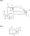
In
In den
Der in
In
Bei dem Ausführungsbeispiel gemäß der
Es sei an dieser Stelle darauf hingewiesen, dass in den vorbeschriebenen Ausführungsbeispielen die Temperatursicherung
Eine Überprüfung der Temperaturüberwachungseinrichtung
BezugszeichenlisteLIST OF REFERENCE NUMBERS
- 11
- radiometrische Messanordnungradiometric measuring arrangement
- 22
- Strahlenquelleradiation source
- 33
- Erfassungseinrichtungdetector
- 55
- Szintillatorscintillator
- 77
- Photomultiplierphotomultiplier
- 99
- Messelektronikmeasuring electronics
- 1010
- TemperaturüberwachungseinrichtungenTemperature monitoring devices
- 1111
- Unterbrechungseinrichtunginterrupting device
- 1313
- TemperatursicherungThermal fuse
- 1414
- Übertragungseinheittransmission unit
- 1515
- Schwingkreisresonant circuit
- 1717
- Abfragevorrichtunginterrogator
- 1919
- RFID-Chip / ÜbertragungseinheitRFID chip / transmission unit
- 2121
- Antenne / SpuleAntenna / coil
- 2323
- erster Kondensatorfirst capacitor
- 2525
- zweiter Kondensatorsecond capacitor
- 6060
- Busbus
- 6262
- Signalleitungsignal line
- ϑθ
- Grenztemperatur limit temperature
Claims (13)
Translated fromGermanPriority Applications (4)
| Application Number | Priority Date | Filing Date | Title |
|---|---|---|---|
| DE102013113633.8ADE102013113633A1 (en) | 2013-12-06 | 2013-12-06 | Radiometric measuring arrangement |
| US14/553,242US20150268358A1 (en) | 2013-12-06 | 2014-11-25 | Radiometric Measuring Device |
| EP14195035.2AEP2881716B1 (en) | 2013-12-06 | 2014-11-26 | Radiometric measuring assembly and use of circuit breakers for indicating the excess of a temperature limit in such a measuring assembly |
| CN201410858401.0ACN104697606A (en) | 2013-12-06 | 2014-12-05 | Radiometric measuring assembly |
Applications Claiming Priority (1)
| Application Number | Priority Date | Filing Date | Title |
|---|---|---|---|
| DE102013113633.8ADE102013113633A1 (en) | 2013-12-06 | 2013-12-06 | Radiometric measuring arrangement |
Publications (1)
| Publication Number | Publication Date |
|---|---|
| DE102013113633A1true DE102013113633A1 (en) | 2015-06-11 |
Family
ID=51947270
Family Applications (1)
| Application Number | Title | Priority Date | Filing Date |
|---|---|---|---|
| DE102013113633.8ACeasedDE102013113633A1 (en) | 2013-12-06 | 2013-12-06 | Radiometric measuring arrangement |
Country Status (4)
| Country | Link |
|---|---|
| US (1) | US20150268358A1 (en) |
| EP (1) | EP2881716B1 (en) |
| CN (1) | CN104697606A (en) |
| DE (1) | DE102013113633A1 (en) |
Cited By (2)
| Publication number | Priority date | Publication date | Assignee | Title |
|---|---|---|---|---|
| DE102016105385A1 (en)* | 2016-03-22 | 2017-09-28 | Vega Grieshaber Kg | Sensor housing and sensor with sensor housing |
| DE102019130713A1 (en)* | 2019-11-14 | 2021-05-20 | Vega Grieshaber Kg | Temperature monitoring device and measuring arrangement with it |
Families Citing this family (5)
| Publication number | Priority date | Publication date | Assignee | Title |
|---|---|---|---|---|
| DE102019134600A1 (en)* | 2019-12-16 | 2021-06-17 | Endress + Hauser Flowtec Ag | Sensor and Coriolis measuring device |
| DE102022103589B3 (en) | 2022-02-16 | 2023-05-04 | Vega Grieshaber Kg | Measuring device of a radiometric measuring device |
| DE102022103590B3 (en) | 2022-02-16 | 2023-05-04 | Vega Grieshaber Kg | Measuring device of a radiometric measuring device |
| DE102022104550B3 (en) | 2022-02-25 | 2023-06-22 | Vega Grieshaber Kg | Measuring device and method for determining the fracture point within a scintillator |
| DE102022105762A1 (en) | 2022-03-11 | 2023-09-14 | Vega Grieshaber Kg | Measuring device of a radiometric measuring device |
Citations (5)
| Publication number | Priority date | Publication date | Assignee | Title |
|---|---|---|---|---|
| US7078703B2 (en)* | 2001-06-29 | 2006-07-18 | Kabushiki Kaisha Toshiba | Control of temperature of flat panel type of radiation detector |
| US20110164724A1 (en)* | 2010-01-05 | 2011-07-07 | Fujifilm Corporation | Radiation image capturing device and radiation image capturing system |
| DE202011005328U1 (en)* | 2011-04-06 | 2011-07-15 | Berthold Technologies Gmbh & Co. Kg | System for the radiometric measurement of at least one process variable |
| GB2484029A (en)* | 2008-10-09 | 2012-03-28 | Schlumberger Holdings | Thermally protected scintillation detector |
| US20130272499A1 (en)* | 2012-04-13 | 2013-10-17 | John Matthew Simmons | Systems and methods for controlling x-ray imaging systems |
Family Cites Families (10)
| Publication number | Priority date | Publication date | Assignee | Title |
|---|---|---|---|---|
| US3192725A (en)* | 1962-11-29 | 1965-07-06 | Exxon Production Research Co | Temperature stabilized radiation detectors |
| US4649015A (en)* | 1984-07-20 | 1987-03-10 | The United States Of America As Represented By The United States Department Of Energy | Monitoring system for a liquid-cooled nuclear fission reactor |
| CN1028308C (en)* | 1988-07-14 | 1995-04-26 | 清华大学 | Temp. controlled autostable system for scintillation detector |
| US5323291A (en)* | 1992-10-15 | 1994-06-21 | Apple Computer, Inc. | Portable computer and docking station having an electromechanical docking/undocking mechanism and a plurality of cooperatively interacting failsafe mechanisms |
| US6806808B1 (en)* | 1999-02-26 | 2004-10-19 | Sri International | Wireless event-recording device with identification codes |
| US6356425B1 (en)* | 2000-04-07 | 2002-03-12 | Koock Elan Jung | Timer-thermal-overload shutoff apparatus |
| US7902514B2 (en)* | 2007-09-25 | 2011-03-08 | Fujifilm Corporation | Image detecting device and image capturing system |
| CN201096508Y (en)* | 2007-11-02 | 2008-08-06 | 黑龙江省中贝技术有限公司 | Flash detector for material level detection |
| CN101571711B (en)* | 2008-04-28 | 2010-12-15 | 同方威视技术股份有限公司 | Monitoring system used in open radiation place |
| CN202885914U (en)* | 2012-11-28 | 2013-04-17 | 黑龙江省中贝技术有限公司 | Combined expansion type flash liquid level control device |
- 2013
- 2013-12-06DEDE102013113633.8Apatent/DE102013113633A1/ennot_activeCeased
- 2014
- 2014-11-25USUS14/553,242patent/US20150268358A1/ennot_activeAbandoned
- 2014-11-26EPEP14195035.2Apatent/EP2881716B1/enactiveActive
- 2014-12-05CNCN201410858401.0Apatent/CN104697606A/ennot_activeWithdrawn
Patent Citations (5)
| Publication number | Priority date | Publication date | Assignee | Title |
|---|---|---|---|---|
| US7078703B2 (en)* | 2001-06-29 | 2006-07-18 | Kabushiki Kaisha Toshiba | Control of temperature of flat panel type of radiation detector |
| GB2484029A (en)* | 2008-10-09 | 2012-03-28 | Schlumberger Holdings | Thermally protected scintillation detector |
| US20110164724A1 (en)* | 2010-01-05 | 2011-07-07 | Fujifilm Corporation | Radiation image capturing device and radiation image capturing system |
| DE202011005328U1 (en)* | 2011-04-06 | 2011-07-15 | Berthold Technologies Gmbh & Co. Kg | System for the radiometric measurement of at least one process variable |
| US20130272499A1 (en)* | 2012-04-13 | 2013-10-17 | John Matthew Simmons | Systems and methods for controlling x-ray imaging systems |
Cited By (2)
| Publication number | Priority date | Publication date | Assignee | Title |
|---|---|---|---|---|
| DE102016105385A1 (en)* | 2016-03-22 | 2017-09-28 | Vega Grieshaber Kg | Sensor housing and sensor with sensor housing |
| DE102019130713A1 (en)* | 2019-11-14 | 2021-05-20 | Vega Grieshaber Kg | Temperature monitoring device and measuring arrangement with it |
Also Published As
| Publication number | Publication date |
|---|---|
| EP2881716A2 (en) | 2015-06-10 |
| EP2881716B1 (en) | 2020-01-01 |
| CN104697606A (en) | 2015-06-10 |
| US20150268358A1 (en) | 2015-09-24 |
| EP2881716A3 (en) | 2015-09-02 |
Similar Documents
| Publication | Publication Date | Title |
|---|---|---|
| EP2881716B1 (en) | Radiometric measuring assembly and use of circuit breakers for indicating the excess of a temperature limit in such a measuring assembly | |
| EP1785703B1 (en) | Method for monitoring and/or determining the condition of a force measuring device and force measuring device | |
| EP2823545B1 (en) | Circuit assembly for the state monitoring and logging of overvoltage protection devices or overvoltage protection systems | |
| EP2724436B1 (en) | State monitoring or diagnostics system | |
| EP2156150B1 (en) | Method for monitoring the state of a force measuring device, force measuring device and force measuring module | |
| EP3699559A1 (en) | Fluid level measuring device | |
| WO2009000919A2 (en) | Device for monitoring the condition of structures | |
| EP3542150B1 (en) | Method for determining a remaining operating period of a detector unit | |
| DE102008062659A1 (en) | Device for monitoring theft of solar generator and inverter of photo-voltaic system, has alternating voltage source checking high frequency characteristics of generator, and evaluation circuit evaluating changes of characteristics | |
| EP1562272B1 (en) | Arrangement for checking and recording of the status of an overvoltage protection device, particularly for installation in low-voltage networks or information systems | |
| DE102009001641B4 (en) | Radiometric measuring arrangement | |
| WO2010012296A1 (en) | Device, arrangement, and method for determining a temperature | |
| AT523070A4 (en) | Method for monitoring lightning activity in a surveillance area | |
| DE102019130713A1 (en) | Temperature monitoring device and measuring arrangement with it | |
| EP0513952B1 (en) | Disturbance detecting circuit for an electronic assembly | |
| DE102008005672B4 (en) | Apparatus and method for detecting structural changes of a component | |
| DE4440389C2 (en) | Combination sensor for the detection of atmospheric variables, in particular for the diagnosis of icing and wind loads on technical objects | |
| EP3262393B1 (en) | Measuring system for measuring vibration | |
| AT527332B1 (en) | ROCKFALL AND AVALANCHE EARLY WARNING SYSTEM | |
| EP1483753B1 (en) | Methane gas-monitoring system comprising at least one ngm (natural gas monitor) sensor device | |
| DE102019127118B4 (en) | Field device | |
| DE102015100166A1 (en) | Method for the sequential arrangement of radiometric measuring instruments | |
| DE102022133798A1 (en) | Radiometric detector arrangement | |
| DE102022104331A1 (en) | System and method for transmitting sensor data and position information, as well as communication module and sensor | |
| DE102022112220A1 (en) | Actuator, safety system and method |
Legal Events
| Date | Code | Title | Description |
|---|---|---|---|
| R012 | Request for examination validly filed | ||
| R082 | Change of representative | Representative=s name:PATENTANWAELTE BAUER VORBERG KAYSER PARTNERSCH, DE | |
| R002 | Refusal decision in examination/registration proceedings | ||
| R003 | Refusal decision now final |