DE102013106926A1 - Method for detecting the degree of filling of a transport route - Google Patents
Method for detecting the degree of filling of a transport routeDownload PDFInfo
- Publication number
- DE102013106926A1 DE102013106926A1DE102013106926.6ADE102013106926ADE102013106926A1DE 102013106926 A1DE102013106926 A1DE 102013106926A1DE 102013106926 ADE102013106926 ADE 102013106926ADE 102013106926 A1DE102013106926 A1DE 102013106926A1
- Authority
- DE
- Germany
- Prior art keywords
- transport
- section
- filling
- degree
- route
- Prior art date
- Legal status (The legal status is an assumption and is not a legal conclusion. Google has not performed a legal analysis and makes no representation as to the accuracy of the status listed.)
- Ceased
Links
- 238000000034methodMethods0.000titleclaimsabstractdescription20
- 230000006870functionEffects0.000claimsdescription9
- 230000008859changeEffects0.000claimsdescription6
- 230000007704transitionEffects0.000claimsdescription5
- 238000001514detection methodMethods0.000abstractdescription3
- 230000004048modificationEffects0.000description3
- 238000012986modificationMethods0.000description3
- 238000011161developmentMethods0.000description2
- 230000018109developmental processEffects0.000description2
- 230000000694effectsEffects0.000description1
- 239000002184metalSubstances0.000description1
- 230000002093peripheral effectEffects0.000description1
- 239000002689soilSubstances0.000description1
- 238000002604ultrasonographyMethods0.000description1
Images
Classifications
- B—PERFORMING OPERATIONS; TRANSPORTING
- B65—CONVEYING; PACKING; STORING; HANDLING THIN OR FILAMENTARY MATERIAL
- B65G—TRANSPORT OR STORAGE DEVICES, e.g. CONVEYORS FOR LOADING OR TIPPING, SHOP CONVEYOR SYSTEMS OR PNEUMATIC TUBE CONVEYORS
- B65G43/00—Control devices, e.g. for safety, warning or fault-correcting
- B65G43/08—Control devices operated by article or material being fed, conveyed or discharged
- B—PERFORMING OPERATIONS; TRANSPORTING
- B65—CONVEYING; PACKING; STORING; HANDLING THIN OR FILAMENTARY MATERIAL
- B65G—TRANSPORT OR STORAGE DEVICES, e.g. CONVEYORS FOR LOADING OR TIPPING, SHOP CONVEYOR SYSTEMS OR PNEUMATIC TUBE CONVEYORS
- B65G47/00—Article or material-handling devices associated with conveyors; Methods employing such devices
- B65G47/34—Devices for discharging articles or materials from conveyor
- B65G47/46—Devices for discharging articles or materials from conveyor and distributing, e.g. automatically, to desired points
- B65G47/51—Devices for discharging articles or materials from conveyor and distributing, e.g. automatically, to desired points according to unprogrammed signals, e.g. influenced by supply situation at destination
- B65G47/5104—Devices for discharging articles or materials from conveyor and distributing, e.g. automatically, to desired points according to unprogrammed signals, e.g. influenced by supply situation at destination for articles
- B—PERFORMING OPERATIONS; TRANSPORTING
- B65—CONVEYING; PACKING; STORING; HANDLING THIN OR FILAMENTARY MATERIAL
- B65G—TRANSPORT OR STORAGE DEVICES, e.g. CONVEYORS FOR LOADING OR TIPPING, SHOP CONVEYOR SYSTEMS OR PNEUMATIC TUBE CONVEYORS
- B65G47/00—Article or material-handling devices associated with conveyors; Methods employing such devices
- B65G47/52—Devices for transferring articles or materials between conveyors i.e. discharging or feeding devices
- B—PERFORMING OPERATIONS; TRANSPORTING
- B65—CONVEYING; PACKING; STORING; HANDLING THIN OR FILAMENTARY MATERIAL
- B65G—TRANSPORT OR STORAGE DEVICES, e.g. CONVEYORS FOR LOADING OR TIPPING, SHOP CONVEYOR SYSTEMS OR PNEUMATIC TUBE CONVEYORS
- B65G2201/00—Indexing codes relating to handling devices, e.g. conveyors, characterised by the type of product or load being conveyed or handled
- B65G2201/02—Articles
- B65G2201/0235—Containers
- B65G2201/0244—Bottles
- B—PERFORMING OPERATIONS; TRANSPORTING
- B65—CONVEYING; PACKING; STORING; HANDLING THIN OR FILAMENTARY MATERIAL
- B65G—TRANSPORT OR STORAGE DEVICES, e.g. CONVEYORS FOR LOADING OR TIPPING, SHOP CONVEYOR SYSTEMS OR PNEUMATIC TUBE CONVEYORS
- B65G2203/00—Indexing code relating to control or detection of the articles or the load carriers during conveying
- B65G2203/04—Detection means
- B65G2203/042—Sensors
- B65G2203/044—Optical
Landscapes
- Engineering & Computer Science (AREA)
- Mechanical Engineering (AREA)
- Control Of Conveyors (AREA)
- Attitude Control For Articles On Conveyors (AREA)
- Measurement Of Levels Of Liquids Or Fluent Solid Materials (AREA)
Abstract
Translated fromGermanDescription
Translated fromGermanDie Erfindung bezieht sich auf ein Verfahren gemäß Oberbegriff Patentanspruch 1.The invention relates to a method according to the preamble of claim 1.
Es ist üblich und bekannt, bei Förderern oder Transportstrecken für Behälter den Füllgrad der jeweiligen Transportstrecke, d. h. beispielsweise den von einem dicht gepackten Behälterstrom eingenommenen Teil einer Transportfläche einer Transportstrecke oder eines Transportstreckenabschnitts über einen oder mehrere Schalter zu erfassen, wobei hiermit allerdings der Zustand der Befüllung der Transportstrecke mit Behältern lediglich abschnittsweise ermittelt werden kann. Bei Einsatz nur eines einzigen Schalters reduziert sich die entsprechende Information allenfalls nur darauf, dass die Transportstrecke entweder komplett mit Behältern belegt oder aber komplett frei ist.It is common and well known in conveyors or transport routes for containers, the degree of filling of the respective transport route, d. H. For example, to detect the occupied by a densely packed container flow part of a transport surface of a transport path or a transport route section via one or more switches, but hereby the condition of filling the transport path with containers can be determined only partially. If only a single switch is used, the corresponding information is at most only reduced to the fact that the transport path is either completely occupied by containers or completely free.
Die Erfassung des Füllgrades einer Transportstrecke ist aber u. a. erforderlich, um die Fördergeschwindigkeit der Transportstrecke in Abhängigkeit von der Leistung (Anzahl der behandelten Behälter je Zeiteinheit) einer der Transportstrecke vorausgehenden Behälterbehandlungsmaschine und/oder einer der Transportstrecke nachfolgenden Behälterbehandlungsmaschine zu steuern, was mit den bisher üblichen Verfahren in optimaler Weise nicht möglich ist. Insbesondere bei wechselnden Fördermengen (Anzahl der mit der Transportstrecke zu fördernden Behälter je Zeiteinheit), die beispielsweise aus augenblicklichen Leistungsänderungen der vor und/oder nach der Transportstrecke in einer Gesamtanlage angeordneten Behälterbehandlungsmaschinen resultieren, ergeben sich u. a. folgende Probleme:
Die Transportgeschwindigkeit, mit der eine einen Pulk bildenden Behältergruppe von der Einlaufseite der Transportstrecke her entlang dieser Transportstrecke zum Anschluss an weitere bereits auf der Transportstrecke vorhandene Behälter transportiert wird, ist überhöht, sodass es zu einem Aufprall zwischen den Behältern kommt, mit einer erhöhten Lärmesmission und der Gefahr eines Umfallens von Behältern.
Weiterhin kann es durch nachfolgende oder nachdrängelnde Behälter zu einem überhöhten Druck im Behälterstrom auf der Transportstrecke kommen, was u. a. zu einer erhöhte Reibung zwischen den Behältern und zu einem erhöhten Verschleiß führt, insbesondere auch mit der Gefahr einer Beschädigung der Behälterausstattung oder der diese Ausstattung bildenden Etiketten, Aufdrucke usw.However, the detection of the degree of filling of a transport path is required, inter alia, in order to control the conveying speed of the transport path as a function of the power (number of treated containers per unit time) of a transport path preceding container treatment machine and / or one of the transport path subsequent container treatment machine, which with the usual Procedure in an optimal manner is not possible. In particular, with changing flow rates (number of containers to be transported with the transport route per unit time) resulting, for example, from instantaneous changes in performance of the container handling machines arranged before and / or after the transport route in an overall plant, the following problems arise, inter alia:
The transport speed at which a container group forming a pulp is transported from the inlet side of the transport path along this transport path for connection to other containers already present on the transport path is excessive, so that an impact between the containers occurs, with an increased noise emission and the risk of overturning of containers.
Furthermore, by subsequent or nachdrängelnde container to an excessive pressure in the container flow on the transport route, resulting inter alia in increased friction between the containers and increased wear, especially with the risk of damage to the container equipment or this equipment forming labels , Imprints etc.
Aufgabe der Erfindung ist es, ein Verfahren aufzuzeigen, welches es ermöglicht, zu jedem Zeitpunkt den aktuellen Füllgrad eines Förderers oder einer Transportstrecke für Transportgüter zu ermitteln. Zur Lösung dieser Aufgabe ist ein Verfahren entsprechend dem Patentanspruch 1 ausgebildet.The object of the invention is to provide a method which makes it possible at any time to determine the current degree of filling of a conveyor or a transport path for goods to be transported. To solve this problem, a method according to claim 1 is formed.
Da mit dem erfindungsgemäßen Verfahren der Füllgrad des Förderers bzw. der Transportstrecke zu jedem Zeitpunkt bekannt ist und damit auch die Verteilung der Transportgüter auf der Transportstrecke, kann die Transportgeschwindigkeit dieser Transportstrecke zu jedem Zeitpunkt z. B. optimal an die augenblickliche Leistung einer der Transportstrecke vorausgehenden Maschine und/oder einer der Transportstrecke nachfolgenden Maschine angepasst werden, d. h. an die Transportgutmenge, die von einer vorausgehenden Maschine zugeführt und/oder an eine nachfolgende Maschine weiter transportiert werden muss.Since with the inventive method, the degree of filling of the conveyor or the transport route is known at any time and thus the distribution of goods to be transported on the transport route, the transport speed of this transport route at any time z. B. optimally adapted to the instantaneous performance of a transport route preceding machine and / or a subsequent transport machine, d. H. to the amount of goods to be transported, which must be supplied by a preceding machine and / or transported to a subsequent machine.
Durch das erfindungsgemäße Verfahren ist ein schonender Transport des Transportgutes bei reduzierter Lärmemission, optimaler Pufferwirkung und damit bei erhöhter Produktivität möglich.The inventive method is a gentle transport of the cargo with reduced noise emission, optimal buffer effect and thus increased productivity possible.
In Weiterbildung der Erfindung ist das Verfahren beispielsweise so ausgebildet,
dass der mehrreihige dicht gepackte Transportgutstrom durch Änderung der Transportrichtung und/oder durch Änderung der Transportgeschwindigkeit und/oder durch eine Neigung der Transportebene quer zur Transportrichtung erzeugt wird,
und/oder
dass der Füllgrad (f) als Funktion eines Quotienten aus der Differenz zwischen einer Gesamtbreite (B) des Transportstreckenabschnitts und dem Abstand zu der Gesamtbreite (B) bestimmt wird, d. h. f = (B – x)/B,
und/oder
dass die Transportgeschwindigkeit der Transportstrecke und/oder des Transportstreckenabschnitts in Abhängigkeit von dem Füllgrad (f) gesteuert wird,
und/oder
dass die Transportgeschwindigkeit der Transportstrecke und/oder des Transportstreckenabschnitts in Abhängigkeit von der Leistung, insbesondere von der Sollleistung (Q-Soll) einer auf die Transportstrecke folgenden Maschine und/oder einer der Transportstrecke vorausgehenden Maschine gesteuert wird,
und/oder
das die Fördergeschwindigkeit der Transportstrecke und/oder des Transportstreckenabschnitts mit einem weiteren Sensor ermittelt wird, der vorzugsweise mit dem wenigstens einem Abstandssensor eine Einheit bildet,
und/oder
dass aus dem kontinuierlich erfassten Füllgrad (f) in dem Rechner eine dem Füllgrad proportionale Größe gebildet wird,
und/oder
dass der jeweils kontinuierlich erfasste Füllgrad (f) in einem Speicher, z. B. Schieberegister einer Steuereinrichtung abgespeichert und hieraus, vorzugsweise auch unter Berücksichtigung einer Transportlänge zwischen der Messposition und der Auslaufseite der Transportstrecke die dem Füllgrad proportionale Größe gebildet wird, beispielsweise in Form eines Mittelwertes und/oder zur optimalen Steuerung der Transportgeschwindigkeit der Transportstrecke oder des Transportstreckenabschnitts,
und/oder
dass der Transportstreckenabschnitt die Auslaufseite der Transportstrecke bildet,
und/oder
dass den Transportgütern vor der wenigstens einen Messstrecke eine wenigstens zweimalige Änderung der Transportrichtung aufgezwungen wird,
und/oder
dass die Transportgüter, vorzugsweise als mehrspuriger Transportgutstrom über einen die Zulaufseite der Transportstrecke bildenden Transportstreckenabschnitt in einer ersten Transportrichtung zugeführt werden, dass dann dem Transportgutstrom auf einem anschließenden Transportstreckenabschnitt eine Änderung der Transportrichtung aufgezwungen und an einem Übergang zwischen dem zweiten Transportstreckenabschnitt und einem dritten Transportstreckenabschnitt eine nochmalige Änderung der Transportrichtung aufgezwungen wird, und dass an der wenigstens einen am dritten Transportstreckenabschnitt vorgesehenen Messstrecke der Füllgrad mit dem wenigstens einen Abstandssensor ermittelt wird,
wobei die vorgenannten Merkmale jeweils einzeln oder in beliebiger Kombination verwendet sein können.In a development of the invention, the method is designed, for example, in such a way that
that the multi-row dense transport goods stream is generated by changing the transport direction and / or by changing the transport speed and / or by an inclination of the transport plane transversely to the transport direction,
and or
that the degree of filling (f) is determined as a function of a quotient of the difference between a total width (B) of the transport path section and the distance to the total width (B), ie f = (B - x) / B,
and or
the transport speed of the transport path and / or of the transport path section is controlled as a function of the degree of filling (f),
and or
the transport speed of the transport path and / or the transport path section is controlled as a function of the power, in particular of the desired power (Q target) of a machine following the transport path and / or of a machine preceding the transport path,
and or
the conveying speed of the transport path and / or of the transport path section is determined with a further sensor, which preferably forms a unit with the at least one distance sensor,
and or
that from the continuously detected degree of filling (f) in the computer a size proportional to the degree of filling is formed,
and or
that the respectively continuously detected filling level (f) in a memory, for. B. shift register of a control device and from this, preferably also taking into account a transport length between the measuring position and the outlet side of the transport path to the degree of filling proportional size is formed, for example in the form of an average value and / or for optimal control of the transport speed of the transport route or the transport route section,
and or
the transport route section forms the outlet side of the transport route,
and or
that the transport goods are forced to change the transport direction at least twice before the at least one measuring path,
and or
in that the transported goods, preferably as a multi-track transport goods stream, are fed in a first transport direction via a transport route section forming the feed side of the transport route, then impose a change in the transport direction on the transport goods stream on a subsequent transport route section and at a transition between the second transport route section and a third transport route section Modification of the transport direction is imposed, and that is determined at the at least one provided on the third transport path section measuring the degree of filling with the at least one distance sensor,
wherein the aforementioned features can be used individually or in any combination.
Unter „Transportgut” sind im Sinne der Erfindung insbesondere Behälter zu verstehen und dabei vor allem auch Behälter in Form von Dosen oder Flaschen aus Metall und/oder Kunststoff.For the purposes of the invention, "goods to be transported" are to be understood as meaning, in particular, containers and, above all, containers in the form of cans or bottles made of metal and / or plastic.
Unter „dicht gepackter mehrreihiger Transportgutstrom” oder „dicht gepackter mehrreihiger Behälterstrom ist im Sinne der Erfindung ein Transportgutstrom oder Behälterstrom zu verstehen, in dem die Transportgüter oder Behälter in Transportrichtung sowie quer hierzu dicht an einander anschließen bzw. an einander anliegen.For the purposes of the invention, "densely packed, multi-row transport goods stream" or "densely packed, multi-row container stream is to be understood as a transport goods stream or container stream in which the transported goods or containers are connected tightly to one another in the transport direction and transversely thereto or abut each other.
Der Ausdruck „im Wesentlichen” bzw. „etwa” bzw. „ca.” bedeutet im Sinne der Erfindung Abweichungen vom jeweils exakten Wert um +/–10%, bevorzugt um +/–5% und/oder Abweichungen in Form von für die Funktion unbedeutenden Änderungen.The term "substantially" or "approximately" or "approx." In the context of the invention means deviations from the exact value by +/- 10%, preferably by +/- 5% and / or deviations in the form of for Function insignificant changes.
Weiterbildungen, Vorteile und Anwendungsmöglichkeiten der Erfindung ergeben sich auch aus der nachfolgenden Beschreibung von Ausführungsbeispielen und aus den Figuren. Dabei sind alle beschriebenen und/oder bildlich dargestellten Merkmale für sich oder in beliebiger Kombination grundsätzlich Gegenstand der Erfindung, unabhängig von ihrer Zusammenfassung in den Ansprüchen oder deren Rückbeziehung. Auch wird der Inhalt der Ansprüche zu einem Bestandteil der Beschreibung gemacht.Further developments, advantages and applications of the invention will become apparent from the following description of exemplary embodiments and from the figures. In this case, all described and / or illustrated features alone or in any combination are fundamentally the subject of the invention, regardless of their summary in the claims or their dependency. Also, the content of the claims is made an integral part of the description.
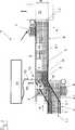
Die Erfindung wird im Folgenden anhand der Figur, die in vereinfachter, schematischer Darstellung und in Draufsicht einen Förderer oder eine Transportstrecke
Die Transportstrecke
Der Transportstreckenabschnitt
Analog hierzu ist der Transportstreckenabschnitt
Der Transportstreckenabschnitt
Es versteht sich, dass die Transportrichtungen A, B und C die angestrebten, Transportrichtungen der Transportstreckenabschnitte
Sämtliche Transportbänder
Die Transportstrecken
Durch die nochmalige Umlenkung der Transportrichtung des Behälterstroms am Übergang zwischen den Förderstreckenabschnitten
In Transportrichtung C auf den Übergang zwischen dem Transportstreckenabschnitten
Mit diesem kontinuierlich ermittelten Füllgrad f erfolgt dann über die Steuerelektronik
Für die Transportgeschwindigkeit V5 gilt dann beispielsweise:
Hierbei ist d der maximale Durchmesser, der jeder Behälter
Bevorzugt wird aus dem kontinuierlich erfassten Füllgrad (f), beispielsweise auch unter Berücksichtigung der Transportlänge zwischen der Messposition
Hierbei wird der kontinuierlich erfasste Füllgrad (f) in einem Speicher, z. B. Schieberegister der Steuereinrichtung
Mit Hilfe der kontinuierlichen Erfassung des Füllgrades f ist somit u. a. eine optimale Steuerung der Transportgeschwindigkeit der Transportstrecke
Die Erfindung wurde voranstehend an einem Ausführungsbeispiel beschrieben. Es versteht sich, dass zahlreiche Änderungen sowie Abwandlungen möglich sind, ohne dass dadurch der die Erfindung tragende Gedanke verlassen wird. So kann anstelle des schräg verlaufenden Führungsgeländeabschnitts
Unabhängig von derartigen Änderungen sowie Abwandlungen ist allen Ausführungen vorzugsweise gemeinsam, dass durch Änderung der Transportrichtung und/oder durch Änderung der Transportgeschwindigkeit und/oder durch eine Neigung der Transportebene an einer Messstrecke der Transportstrecke ein pulkartiger oder dicht gepackter mehrspuriger Behälterstrom (Behälterstrom
BezugszeichenlisteLIST OF REFERENCE NUMBERS
- 11
- Förderer oder TransportstreckeConveyor or transport route
- 22
- Behältercontainer
- 3–53-5
- TransportstreckenabschnittTransport stretch
- 3.1, 5.13.1, 5.1
- Transportbandconveyor belt
- 6, 76, 7
- Antrieb für die Transportbänder
3.1 und5.1 Drive for the conveyor belts3.1 and5.1 - 8, 98, 9
- Führungsgeländerguide railings
- 9.19.1
- schräg verlaufender Führungsgeländerabschnittoblique guide railing section
- 1010
- Behälterstromcontainer flow
- 1111
- dicht gedrängter mehrspuriger Behälterstromtightly packed multi-lane container stream
- 1212
- Messstreckemeasuring distance
- 1313
- Abstandssensordistance sensor
- 1414
- Steuerrechnertax calculator
- 1515
- BehälterbehandlungsmaschineContainer handling machine
- A, B, CA, B, C
- Transportrichtungtransport direction
Claims (11)
Translated fromGermanPriority Applications (5)
| Application Number | Priority Date | Filing Date | Title |
|---|---|---|---|
| DE102013106926.6ADE102013106926A1 (en) | 2013-07-02 | 2013-07-02 | Method for detecting the degree of filling of a transport route |
| EP14739066.0AEP3016892A1 (en) | 2013-07-02 | 2014-06-23 | Method for detecting the fill level of a transport section |
| BR112015032098ABR112015032098A2 (en) | 2013-07-02 | 2014-06-23 | method for detecting the fill level of a transport section |
| PCT/EP2014/063097WO2015000728A1 (en) | 2013-07-02 | 2014-06-23 | Method for detecting the fill level of a transport section |
| US14/902,633US20160167889A1 (en) | 2013-07-02 | 2014-06-23 | Method for detecting the fill level of a transport section |
Applications Claiming Priority (1)
| Application Number | Priority Date | Filing Date | Title |
|---|---|---|---|
| DE102013106926.6ADE102013106926A1 (en) | 2013-07-02 | 2013-07-02 | Method for detecting the degree of filling of a transport route |
Publications (1)
| Publication Number | Publication Date |
|---|---|
| DE102013106926A1true DE102013106926A1 (en) | 2015-01-08 |
Family
ID=51178878
Family Applications (1)
| Application Number | Title | Priority Date | Filing Date |
|---|---|---|---|
| DE102013106926.6ACeasedDE102013106926A1 (en) | 2013-07-02 | 2013-07-02 | Method for detecting the degree of filling of a transport route |
Country Status (5)
| Country | Link |
|---|---|
| US (1) | US20160167889A1 (en) |
| EP (1) | EP3016892A1 (en) |
| BR (1) | BR112015032098A2 (en) |
| DE (1) | DE102013106926A1 (en) |
| WO (1) | WO2015000728A1 (en) |
Cited By (3)
| Publication number | Priority date | Publication date | Assignee | Title |
|---|---|---|---|---|
| WO2018091155A1 (en)* | 2016-11-15 | 2018-05-24 | Krones Ag | Device and method for ascertaining a degree of occupancy of a transport device |
| WO2018108326A1 (en)* | 2016-12-13 | 2018-06-21 | Krones Aktiengesellschaft | Apparatus and method for handling articles moving one after the other |
| EP3514085A1 (en)* | 2018-01-18 | 2019-07-24 | M. Tanner AG | Transport and supply unit for preforms |
Citations (3)
| Publication number | Priority date | Publication date | Assignee | Title |
|---|---|---|---|---|
| EP0190090A1 (en)* | 1985-01-15 | 1986-08-06 | Société Anonyme dite: GEBO | Apparatus for aligning objects without pressure, especially containers, and its controlling device |
| DE4434176A1 (en)* | 1994-09-24 | 1996-03-28 | Khs Masch & Anlagenbau Ag | Capacity-related feed to machinery in bottle-handling plants |
| DE19530626A1 (en)* | 1995-08-21 | 1997-02-27 | Kronseder Maschf Krones | Orderly arranging bottles on conveyor belt |
Family Cites Families (6)
| Publication number | Priority date | Publication date | Assignee | Title |
|---|---|---|---|---|
| DE4129907A1 (en)* | 1991-09-09 | 1993-03-18 | Harald R Bruder | Measurement and control of container flow in conveyor system - using banks of proximity sensors to measures containers passing point for determination of conveyor speed correction |
| WO2003104116A1 (en)* | 2002-06-06 | 2003-12-18 | Flexfactory Ag | Transport of bulk material items |
| US6648125B1 (en)* | 2002-12-09 | 2003-11-18 | B E Design Automation, Inc. | Apparatus for evenly spacing packages on an assembly machine |
| DE202006002351U1 (en)* | 2006-02-15 | 2007-06-28 | Krones Ag | Device for separating objects |
| DE102007042042B4 (en)* | 2007-09-05 | 2020-03-26 | Endress+Hauser SE+Co. KG | Method for determining and monitoring the fill level of a medium in a container using a transit time measurement method |
| DK2693362T3 (en)* | 2012-07-31 | 2015-07-27 | Sick Ag | Detection system for mounting on a conveyor belt |
- 2013
- 2013-07-02DEDE102013106926.6Apatent/DE102013106926A1/ennot_activeCeased
- 2014
- 2014-06-23BRBR112015032098Apatent/BR112015032098A2/ennot_activeApplication Discontinuation
- 2014-06-23WOPCT/EP2014/063097patent/WO2015000728A1/enactiveApplication Filing
- 2014-06-23EPEP14739066.0Apatent/EP3016892A1/ennot_activeCeased
- 2014-06-23USUS14/902,633patent/US20160167889A1/ennot_activeAbandoned
Patent Citations (3)
| Publication number | Priority date | Publication date | Assignee | Title |
|---|---|---|---|---|
| EP0190090A1 (en)* | 1985-01-15 | 1986-08-06 | Société Anonyme dite: GEBO | Apparatus for aligning objects without pressure, especially containers, and its controlling device |
| DE4434176A1 (en)* | 1994-09-24 | 1996-03-28 | Khs Masch & Anlagenbau Ag | Capacity-related feed to machinery in bottle-handling plants |
| DE19530626A1 (en)* | 1995-08-21 | 1997-02-27 | Kronseder Maschf Krones | Orderly arranging bottles on conveyor belt |
Cited By (4)
| Publication number | Priority date | Publication date | Assignee | Title |
|---|---|---|---|---|
| WO2018091155A1 (en)* | 2016-11-15 | 2018-05-24 | Krones Ag | Device and method for ascertaining a degree of occupancy of a transport device |
| WO2018108326A1 (en)* | 2016-12-13 | 2018-06-21 | Krones Aktiengesellschaft | Apparatus and method for handling articles moving one after the other |
| EP4201851A1 (en)* | 2016-12-13 | 2023-06-28 | Krones Aktiengesellschaft | Device and method for handling piece goods moved one after the other |
| EP3514085A1 (en)* | 2018-01-18 | 2019-07-24 | M. Tanner AG | Transport and supply unit for preforms |
Also Published As
| Publication number | Publication date |
|---|---|
| EP3016892A1 (en) | 2016-05-11 |
| BR112015032098A2 (en) | 2017-07-25 |
| US20160167889A1 (en) | 2016-06-16 |
| WO2015000728A1 (en) | 2015-01-08 |
Similar Documents
| Publication | Publication Date | Title |
|---|---|---|
| EP3115322B1 (en) | Method and device for depalletizing tires | |
| EP2586712B1 (en) | Method and device for inserting products into containers in a robot street | |
| DE60308498T2 (en) | CONTAINERS FOR CONTAINERS SUCH AS BOTTLES | |
| DE102007047828A1 (en) | Scraper chain conveyor for transporting material, has two sensors attached to side of conveyor, where one sensor is attached to shaft and other sensor is attached to chain wheel rotatable relative to shaft | |
| DE3926735A1 (en) | METHOD AND DEVICE FOR FEEDING BOTTLES OR THE LIKE | |
| DE102013106926A1 (en) | Method for detecting the degree of filling of a transport route | |
| DE102006024657A1 (en) | Transport goods e.g. container, rotating device for use in beverage industry, has conveyor with transport devices running parallel to one another, where speed and/or direction of transport devices are controllable independent of each other | |
| DE202005013125U1 (en) | Single-lane container e.g. bottle, flow forming apparatus, has conveyors for container flow, intermediate area connected in conveyor, and separating area connecting intermediate area with conveyors | |
| EP2691943B1 (en) | Method and transport device for returning empty packaging, particularly bottles and cans | |
| DE102010035126A1 (en) | Method and device for the controlled transfer of a piece goods from a feed conveyor to a conveyor | |
| DE2937496A1 (en) | DEVICE FOR SEPARATING AND TRANSPORTING IN THE LATERAL DIRECTION OF ROD MATERIAL | |
| DE102004023181B4 (en) | Feeding machine | |
| DE1532585A1 (en) | Installation on bottle handling machines | |
| DD244112A1 (en) | DEVICE FOR TRANSFERRING OBJECTS | |
| CH662071A5 (en) | Device for feeding BETONSTAHLSTAEBEN TO A PROCESSING MACHINE. | |
| DE102014111428A1 (en) | Device for converting a narrow container stream into a wide container stream | |
| DE68917390T2 (en) | Device for the pressure-free alignment of various objects, in particular bottles. | |
| DE102020134232A1 (en) | Thermal treatment device and method of operating the thermal treatment device | |
| DE8500522U1 (en) | Device for bringing together a stream of bottles to form a closed row of bottles | |
| DE4133588A1 (en) | ARRANGEMENT FOR FORMING A REQUIRED MULTI-TRACK CONTAINER CURRENT INTO A SINGLE-LINE CONTAINER CURRENT TO BE RECOVERED | |
| DE102010053049B3 (en) | Device for storing objects and apparatus and method for treating objects | |
| DE3912008A1 (en) | Separator for timber bundles | |
| EP2243729A2 (en) | Transport device and method for feeding fluid containers into a packaging machine | |
| EP0536703A1 (en) | Arrangement for transforming a multi-lane stream of containers into a single-lane stream | |
| DE102018212267A1 (en) | Method and device for supplying a container mass flow to at least one alley |
Legal Events
| Date | Code | Title | Description |
|---|---|---|---|
| R012 | Request for examination validly filed | ||
| R016 | Response to examination communication | ||
| R002 | Refusal decision in examination/registration proceedings | ||
| R003 | Refusal decision now final |