DE102013106532A1 - Gas container with several pressure vessels - Google Patents
Gas container with several pressure vesselsDownload PDFInfo
- Publication number
- DE102013106532A1 DE102013106532A1DE201310106532DE102013106532ADE102013106532A1DE 102013106532 A1DE102013106532 A1DE 102013106532A1DE 201310106532DE201310106532DE 201310106532DE 102013106532 ADE102013106532 ADE 102013106532ADE 102013106532 A1DE102013106532 A1DE 102013106532A1
- Authority
- DE
- Germany
- Prior art keywords
- gas
- distributor
- oil
- gas container
- lines
- Prior art date
- Legal status (The legal status is an assumption and is not a legal conclusion. Google has not performed a legal analysis and makes no representation as to the accuracy of the status listed.)
- Ceased
Links
- 239000003921oilSubstances0.000claimsabstractdescription37
- 239000010720hydraulic oilSubstances0.000claimsabstractdescription11
- VNWKTOKETHGBQD-UHFFFAOYSA-NmethaneChemical compoundCVNWKTOKETHGBQD-UHFFFAOYSA-N0.000claimsdescription8
- 239000002131composite materialSubstances0.000claimsdescription3
- 229920000049Carbon (fiber)Polymers0.000claimsdescription2
- 239000004917carbon fiberSubstances0.000claimsdescription2
- 239000003365glass fiberSubstances0.000claimsdescription2
- 239000004033plasticSubstances0.000claims1
- 239000007789gasSubstances0.000description59
- 229910000831SteelInorganic materials0.000description3
- 239000003345natural gasSubstances0.000description3
- 239000010959steelSubstances0.000description3
- 238000000265homogenisationMethods0.000description2
- 238000000034methodMethods0.000description2
- BUHVIAUBTBOHAG-FOYDDCNASA-N(2r,3r,4s,5r)-2-[6-[[2-(3,5-dimethoxyphenyl)-2-(2-methylphenyl)ethyl]amino]purin-9-yl]-5-(hydroxymethyl)oxolane-3,4-diolChemical compoundCOC1=CC(OC)=CC(C(CNC=2C=3N=CN(C=3N=CN=2)[C@H]2[C@@H]([C@H](O)[C@@H](CO)O2)O)C=2C(=CC=CC=2)C)=C1BUHVIAUBTBOHAG-FOYDDCNASA-N0.000description1
- 230000001914calming effectEffects0.000description1
- 238000009833condensationMethods0.000description1
- 230000005494condensationEffects0.000description1
- 238000001514detection methodMethods0.000description1
- 238000007599dischargingMethods0.000description1
- 238000006073displacement reactionMethods0.000description1
- 238000009434installationMethods0.000description1
- 239000002985plastic filmSubstances0.000description1
- 229920006255plastic filmPolymers0.000description1
Images


Classifications
- F—MECHANICAL ENGINEERING; LIGHTING; HEATING; WEAPONS; BLASTING
- F17—STORING OR DISTRIBUTING GASES OR LIQUIDS
- F17C—VESSELS FOR CONTAINING OR STORING COMPRESSED, LIQUEFIED OR SOLIDIFIED GASES; FIXED-CAPACITY GAS-HOLDERS; FILLING VESSELS WITH, OR DISCHARGING FROM VESSELS, COMPRESSED, LIQUEFIED, OR SOLIDIFIED GASES
- F17C5/00—Methods or apparatus for filling containers with liquefied, solidified, or compressed gases under pressures
- F17C5/06—Methods or apparatus for filling containers with liquefied, solidified, or compressed gases under pressures for filling with compressed gases
- F—MECHANICAL ENGINEERING; LIGHTING; HEATING; WEAPONS; BLASTING
- F17—STORING OR DISTRIBUTING GASES OR LIQUIDS
- F17C—VESSELS FOR CONTAINING OR STORING COMPRESSED, LIQUEFIED OR SOLIDIFIED GASES; FIXED-CAPACITY GAS-HOLDERS; FILLING VESSELS WITH, OR DISCHARGING FROM VESSELS, COMPRESSED, LIQUEFIED, OR SOLIDIFIED GASES
- F17C9/00—Methods or apparatus for discharging liquefied or solidified gases from vessels not under pressure
- F—MECHANICAL ENGINEERING; LIGHTING; HEATING; WEAPONS; BLASTING
- F17—STORING OR DISTRIBUTING GASES OR LIQUIDS
- F17C—VESSELS FOR CONTAINING OR STORING COMPRESSED, LIQUEFIED OR SOLIDIFIED GASES; FIXED-CAPACITY GAS-HOLDERS; FILLING VESSELS WITH, OR DISCHARGING FROM VESSELS, COMPRESSED, LIQUEFIED, OR SOLIDIFIED GASES
- F17C2201/00—Vessel construction, in particular geometry, arrangement or size
- F17C2201/01—Shape
- F17C2201/0104—Shape cylindrical
- F17C2201/0109—Shape cylindrical with exteriorly curved end-piece
- F—MECHANICAL ENGINEERING; LIGHTING; HEATING; WEAPONS; BLASTING
- F17—STORING OR DISTRIBUTING GASES OR LIQUIDS
- F17C—VESSELS FOR CONTAINING OR STORING COMPRESSED, LIQUEFIED OR SOLIDIFIED GASES; FIXED-CAPACITY GAS-HOLDERS; FILLING VESSELS WITH, OR DISCHARGING FROM VESSELS, COMPRESSED, LIQUEFIED, OR SOLIDIFIED GASES
- F17C2201/00—Vessel construction, in particular geometry, arrangement or size
- F17C2201/05—Size
- F17C2201/056—Small (<1 m3)
- F—MECHANICAL ENGINEERING; LIGHTING; HEATING; WEAPONS; BLASTING
- F17—STORING OR DISTRIBUTING GASES OR LIQUIDS
- F17C—VESSELS FOR CONTAINING OR STORING COMPRESSED, LIQUEFIED OR SOLIDIFIED GASES; FIXED-CAPACITY GAS-HOLDERS; FILLING VESSELS WITH, OR DISCHARGING FROM VESSELS, COMPRESSED, LIQUEFIED, OR SOLIDIFIED GASES
- F17C2201/00—Vessel construction, in particular geometry, arrangement or size
- F17C2201/05—Size
- F17C2201/058—Size portable (<30 l)
- F—MECHANICAL ENGINEERING; LIGHTING; HEATING; WEAPONS; BLASTING
- F17—STORING OR DISTRIBUTING GASES OR LIQUIDS
- F17C—VESSELS FOR CONTAINING OR STORING COMPRESSED, LIQUEFIED OR SOLIDIFIED GASES; FIXED-CAPACITY GAS-HOLDERS; FILLING VESSELS WITH, OR DISCHARGING FROM VESSELS, COMPRESSED, LIQUEFIED, OR SOLIDIFIED GASES
- F17C2203/00—Vessel construction, in particular walls or details thereof
- F17C2203/06—Materials for walls or layers thereof; Properties or structures of walls or their materials
- F17C2203/0602—Wall structures; Special features thereof
- F17C2203/0612—Wall structures
- F17C2203/0614—Single wall
- F17C2203/0617—Single wall with one layer
- F—MECHANICAL ENGINEERING; LIGHTING; HEATING; WEAPONS; BLASTING
- F17—STORING OR DISTRIBUTING GASES OR LIQUIDS
- F17C—VESSELS FOR CONTAINING OR STORING COMPRESSED, LIQUEFIED OR SOLIDIFIED GASES; FIXED-CAPACITY GAS-HOLDERS; FILLING VESSELS WITH, OR DISCHARGING FROM VESSELS, COMPRESSED, LIQUEFIED, OR SOLIDIFIED GASES
- F17C2203/00—Vessel construction, in particular walls or details thereof
- F17C2203/06—Materials for walls or layers thereof; Properties or structures of walls or their materials
- F17C2203/0634—Materials for walls or layers thereof
- F17C2203/0658—Synthetics
- F17C2203/0663—Synthetics in form of fibers or filaments
- F—MECHANICAL ENGINEERING; LIGHTING; HEATING; WEAPONS; BLASTING
- F17—STORING OR DISTRIBUTING GASES OR LIQUIDS
- F17C—VESSELS FOR CONTAINING OR STORING COMPRESSED, LIQUEFIED OR SOLIDIFIED GASES; FIXED-CAPACITY GAS-HOLDERS; FILLING VESSELS WITH, OR DISCHARGING FROM VESSELS, COMPRESSED, LIQUEFIED, OR SOLIDIFIED GASES
- F17C2205/00—Vessel construction, in particular mounting arrangements, attachments or identifications means
- F17C2205/01—Mounting arrangements
- F17C2205/0123—Mounting arrangements characterised by number of vessels
- F17C2205/013—Two or more vessels
- F17C2205/0134—Two or more vessels characterised by the presence of fluid connection between vessels
- F17C2205/0142—Two or more vessels characterised by the presence of fluid connection between vessels bundled in parallel
- F—MECHANICAL ENGINEERING; LIGHTING; HEATING; WEAPONS; BLASTING
- F17—STORING OR DISTRIBUTING GASES OR LIQUIDS
- F17C—VESSELS FOR CONTAINING OR STORING COMPRESSED, LIQUEFIED OR SOLIDIFIED GASES; FIXED-CAPACITY GAS-HOLDERS; FILLING VESSELS WITH, OR DISCHARGING FROM VESSELS, COMPRESSED, LIQUEFIED, OR SOLIDIFIED GASES
- F17C2205/00—Vessel construction, in particular mounting arrangements, attachments or identifications means
- F17C2205/01—Mounting arrangements
- F17C2205/0123—Mounting arrangements characterised by number of vessels
- F17C2205/013—Two or more vessels
- F17C2205/0134—Two or more vessels characterised by the presence of fluid connection between vessels
- F17C2205/0146—Two or more vessels characterised by the presence of fluid connection between vessels with details of the manifold
- F—MECHANICAL ENGINEERING; LIGHTING; HEATING; WEAPONS; BLASTING
- F17—STORING OR DISTRIBUTING GASES OR LIQUIDS
- F17C—VESSELS FOR CONTAINING OR STORING COMPRESSED, LIQUEFIED OR SOLIDIFIED GASES; FIXED-CAPACITY GAS-HOLDERS; FILLING VESSELS WITH, OR DISCHARGING FROM VESSELS, COMPRESSED, LIQUEFIED, OR SOLIDIFIED GASES
- F17C2221/00—Handled fluid, in particular type of fluid
- F17C2221/03—Mixtures
- F17C2221/032—Hydrocarbons
- F17C2221/033—Methane, e.g. natural gas, CNG, LNG, GNL, GNC, PLNG
- F—MECHANICAL ENGINEERING; LIGHTING; HEATING; WEAPONS; BLASTING
- F17—STORING OR DISTRIBUTING GASES OR LIQUIDS
- F17C—VESSELS FOR CONTAINING OR STORING COMPRESSED, LIQUEFIED OR SOLIDIFIED GASES; FIXED-CAPACITY GAS-HOLDERS; FILLING VESSELS WITH, OR DISCHARGING FROM VESSELS, COMPRESSED, LIQUEFIED, OR SOLIDIFIED GASES
- F17C2223/00—Handled fluid before transfer, i.e. state of fluid when stored in the vessel or before transfer from the vessel
- F17C2223/01—Handled fluid before transfer, i.e. state of fluid when stored in the vessel or before transfer from the vessel characterised by the phase
- F17C2223/0107—Single phase
- F17C2223/0123—Single phase gaseous, e.g. CNG, GNC
- F—MECHANICAL ENGINEERING; LIGHTING; HEATING; WEAPONS; BLASTING
- F17—STORING OR DISTRIBUTING GASES OR LIQUIDS
- F17C—VESSELS FOR CONTAINING OR STORING COMPRESSED, LIQUEFIED OR SOLIDIFIED GASES; FIXED-CAPACITY GAS-HOLDERS; FILLING VESSELS WITH, OR DISCHARGING FROM VESSELS, COMPRESSED, LIQUEFIED, OR SOLIDIFIED GASES
- F17C2223/00—Handled fluid before transfer, i.e. state of fluid when stored in the vessel or before transfer from the vessel
- F17C2223/03—Handled fluid before transfer, i.e. state of fluid when stored in the vessel or before transfer from the vessel characterised by the pressure level
- F17C2223/036—Very high pressure (>80 bar)
- F—MECHANICAL ENGINEERING; LIGHTING; HEATING; WEAPONS; BLASTING
- F17—STORING OR DISTRIBUTING GASES OR LIQUIDS
- F17C—VESSELS FOR CONTAINING OR STORING COMPRESSED, LIQUEFIED OR SOLIDIFIED GASES; FIXED-CAPACITY GAS-HOLDERS; FILLING VESSELS WITH, OR DISCHARGING FROM VESSELS, COMPRESSED, LIQUEFIED, OR SOLIDIFIED GASES
- F17C2227/00—Transfer of fluids, i.e. method or means for transferring the fluid; Heat exchange with the fluid
- F17C2227/01—Propulsion of the fluid
- F17C2227/0192—Propulsion of the fluid by using a working fluid
- F—MECHANICAL ENGINEERING; LIGHTING; HEATING; WEAPONS; BLASTING
- F17—STORING OR DISTRIBUTING GASES OR LIQUIDS
- F17C—VESSELS FOR CONTAINING OR STORING COMPRESSED, LIQUEFIED OR SOLIDIFIED GASES; FIXED-CAPACITY GAS-HOLDERS; FILLING VESSELS WITH, OR DISCHARGING FROM VESSELS, COMPRESSED, LIQUEFIED, OR SOLIDIFIED GASES
- F17C2227/00—Transfer of fluids, i.e. method or means for transferring the fluid; Heat exchange with the fluid
- F17C2227/04—Methods for emptying or filling
- F17C2227/046—Methods for emptying or filling by even emptying or filling
- F—MECHANICAL ENGINEERING; LIGHTING; HEATING; WEAPONS; BLASTING
- F17—STORING OR DISTRIBUTING GASES OR LIQUIDS
- F17C—VESSELS FOR CONTAINING OR STORING COMPRESSED, LIQUEFIED OR SOLIDIFIED GASES; FIXED-CAPACITY GAS-HOLDERS; FILLING VESSELS WITH, OR DISCHARGING FROM VESSELS, COMPRESSED, LIQUEFIED, OR SOLIDIFIED GASES
- F17C2270/00—Applications
- F17C2270/01—Applications for fluid transport or storage
- F17C2270/0165—Applications for fluid transport or storage on the road
- F17C2270/0168—Applications for fluid transport or storage on the road by vehicles
- F17C2270/0171—Trucks
Landscapes
- Engineering & Computer Science (AREA)
- Mechanical Engineering (AREA)
- General Engineering & Computer Science (AREA)
- Filling Or Discharging Of Gas Storage Vessels (AREA)
Abstract
Translated fromGermanDescription
Translated fromGermanDie Erfindung betrifft einen Gascontainer mit mehreren Druckbehältern (
Stand der TechnikState of the art
Erdgas wird überwiegend über Rohrleitungen, so genannte Pipelines, transportiert. Falls jedoch eine Pipeline-Infrastruktur fehlt, werden vermehrt Lastkraftwagen für den Erdgas-Transport eingesetzt. Auf den Fahrzeugen sind Druckbehälter fest montiert, die das unter einem Hochdruck von 200 bis 250 bar stehende Gas enthalten.Natural gas is mainly transported via pipelines, so-called pipelines. However, if a pipeline infrastructure is lacking, trucks are increasingly used for natural gas transport. On the vehicles pressure vessels are firmly mounted, which contain the standing under a high pressure of 200 to 250 bar gas.
Zum Beladen strömt das durch einen Verdichter auf Druck gebrachte Gas durch entsprechende Anschlussleitungen in die Druckbehälter. Das Entladen erfolgt in umgekehrter Richtung über dieselben Leitungen.For loading, the gas pressurized by a compressor flows through corresponding connection lines into the pressure vessels. Discharging takes place in the opposite direction over the same lines.
Wenn das Gas aus den Druckbehältern des Transportfahrzeuges in ein Gaslager mit einem hohen Druckniveau eingespeist werden soll, ist eine Gasströmung bei gleichbleibend hohem Druck wirtschaftlich und ökologisch besonders vorteilhaft. Im Stand der Technik ist es bekannt, hierzu das Gas mittels Hydrauliköl von unten nach oben hin zu verdrängen. Dabei wird durch ein Hydraulikaggregat das Öl von unten in die Druckbehälter gefördert.If the gas from the pressure vessels of the transport vehicle to be fed into a gas bearing with a high pressure level, a gas flow at a consistently high pressure economically and environmentally particularly advantageous. In the prior art, it is known to displace the gas by means of hydraulic oil from bottom to top. In this case, the oil is pumped from below into the pressure vessel by a hydraulic unit.
Die Behälter im Transportfahrzeug sind zu Gruppen mit jeweils mehreren Behältern zusammengefasst. Diese Einheiten, auch Sektionen genannt, besitzen ein verbindendes Rohrleitungssystem für das Gas und eins für das Öl. Beim Entladen strömt das Öl gleichzeitig in die Behälter einer Sektion ein. Der Zyklus ist beendet, wenn das Gas bis auf ein Restvolumen aus den Behältern gefördert wurde. Bei diesem Vorgang ist sicher zu stellen, dass kein Öl mit in das abströmende Gas gelangt. Notwendig sind daher gleiche Öl-Pegelstände während der Entleerung und in diesem Zusammenhang gleich große Öl-Volumenströme durch die Rohre der einzelnen Behälterleitungen.The containers in the transport vehicle are grouped together with several containers. These units, also called sections, have a connecting piping system for the gas and one for the oil. During unloading, the oil flows simultaneously into the containers of a section. The cycle is completed when the gas has been pumped out of the containers except for a residual volume. During this process, make sure that no oil gets into the gas flowing out. Therefore, it is necessary to have the same oil level levels during emptying and, in this connection, equal volume of oil volume flows through the tubes of the individual container lines.
Bei einem Entladezyklus ist es also notwendig, dass alle Druckbehälter vom einströmenden Öl gleichmäßig beaufschlagt werden und die Ölvolumina in jedem zu entleerenden Druckbehälter innerhalb des Entladezyklus gleich sind.In a discharge cycle, it is therefore necessary that all pressure vessels are uniformly acted upon by the inflowing oil and the oil volumes in each pressure vessel to be emptied within the discharge cycle are the same.
Ist die Sektion entleert, wird die Gasleitung verschlossen und die Ölleitung auf die Rücklaufleitung umgeschaltet. Nun presst das unter Druck stehende Restgasvolumen das Öl in das drucklose Hydraulikaggregat zurück. Während dieser Zeit strömt in eine nächste Sektion über die Hydraulik-Druckleitung Öl ein und presst das Gas aus. Die Gas-Entleer- und die Öl-zurück-Zyklen verlaufen gleichzeitig und verkürzen so die Gesamtentladezeit.If the section is emptied, the gas line is closed and the oil line switched to the return line. Now the residual gas volume under pressure forces the oil back into the pressureless hydraulic power unit. During this time, oil flows into a next section via the hydraulic pressure line and expels the gas. The gas-depleting and oil-return cycles run simultaneously, reducing overall discharge time.
Im Stand der Technik sind in den Gascontainern der Transportfahrzeuge Stahlflaschen als Druckbehälter vorgesehen, die fest auf dem Fahrzeug bzw. innerhalb des Containers montiert sind. Infolge des Gewichtes der Stahlflaschen und der maximal zulässigen Nutzlast des Fahrzeugs können nur eine begrenzte Anzahl montiert werden, und es verbleibt relativ viel freier Raum zwischen den Flaschen. Dies gestattet die freie Wahl der Behälterpositionen, so dass deshalb die Behälter-Zuleitungen innerhalb einer Sektion geometrisch identisch ausgeführt und angeordnet werden können. Andererseits erzwingt die symmetrische Anordnung der Rohrleitungen die Position der Behälter und legt sie fest.In the prior art, steel cylinders are provided as pressure vessels in the gas containers of the transport vehicles, which are firmly mounted on the vehicle or within the container. Due to the weight of the steel bottles and the maximum allowable payload of the vehicle, only a limited number can be mounted and there is a relatively large amount of free space between the bottles. This allows the free choice of container positions, so that therefore the container supply lines can be performed geometrically identical and arranged within a section. On the other hand, the symmetrical arrangement of the pipes enforces the position of the containers and fixes them.
Die gleichmäßige Gasverdrängung durch das einströmende Hydrauliköl wird im Stand der Technik durch weite, mit großen Krümmungsradien versehene und geometrisch gleiche Gas-Rohrleitungen von den Druckbehältern in jeder Sektion zur Gassammelleitung sowie weite, geometrisch gleiche Öl-Rohrleitungen von den Behältern in jeder Sektion zu den Öl-Sammelleitungen hin erreicht. Die Stahlflaschen und die Rohrleitungen lassen sich aufgrund des vorhandenen freien Raumes problemlos so anordnen, dass die gleiche Geometrie erreicht wird.The uniform gas displacement by the inflowing hydraulic oil is in the prior art by wide, provided with large radii of curvature and geometrically equal gas piping from the pressure vessels in each section to the gas manifold and wide, geometrically equal oil piping from the containers in each section to the oil Collection lines reached. The steel bottles and pipelines can be easily arranged due to the available free space, so that the same geometry is achieved.
Bekannte Anordnungen von Gascontainern bzw. Systemen zur Abgabe von druckbeaufschlagtem Gas sind aus der
Von Vorteil wäre die Verwendung von leichteren, aber hochfesten Gasdruckbehältern, von denen aufgrund des Gewichtes eine erheblich größere Anzahl auf dem Transportfahrzeug montiert werden kann und somit den Transport einer erheblich größeren Gasmenge bei gleichen äußeren Ausmaßen des Transportfahrzeuges bzw. des Containers erlaubt. Bei solchen leichteren Gasdruckbehältern wären diese aber sehr dicht gepackt, so dass geometrisch gleiche Rohrleitungen für Öl und Gas von den Behältern zur jeweiligen Sammelleitung hin aus räumlichen Gründen nicht mehr möglich sind und sich die Rohrleitungen in die kleinen Zwischenräume schmiegen müssen. In Folge wird es nötig, kleine Rohrquerschnitte mit engen Krümmungsradien der Rohrbögen zu verbauen. Der Rohrverlauf zu den einzelnen Behältern ist individuell und ungleich.An advantage would be the use of lighter, but high-strength gas pressure vessels, of which a considerably larger number can be mounted on the transport vehicle due to the weight and thus allows the transport of a significantly larger amount of gas at the same outer dimensions of the transport vehicle or the container. In such lighter gas pressure vessels, however, these would be very densely packed, so that geometrically equal piping for oil and gas from the containers to the respective manifold out of space reasons are no longer possible and the pipes must nestle in the small spaces. As a result, it becomes necessary to obstruct small pipe cross-sections with narrow radii of curvature of the pipe bends. The course of the pipe to the individual containers is individual and unequal.
Aufgabe und Lösung der Erfindung Task and solution of the invention
Aufgabe der Erfindung: Bei einem Gascontainer der eingangs genannten Art soll eine erheblich größere Gasmenge bei dennoch gleichen Container-Abmessungen und gleichem maximalem Gasdruck transportierbar sein, wobei sich außerdem bei der Entladung die Druckbehälter gleichmäßig bis auf das Restvolumen von Gas entleeren sollen. Außerdem sollen ein Öleintrag in den abströmenden Gasstrom und ein Gaseintrag in den abströmenden Ölstrom vermieden werden.OBJECT OF THE INVENTION: In a gas container of the type mentioned, a considerably larger amount of gas should nevertheless be transportable with the same container dimensions and the same maximum gas pressure, wherein the pressure vessels should also be emptied evenly to the residual volume of gas during discharge. In addition, an oil entry into the outflowing gas flow and a gas entry into the outflowing oil flow should be avoided.
Diese Aufgabe wird bei einem Gascontainer mit mehreren Druckbehältern der eingangs genannten Art erfindungsgemäß dadurch gelöst, dass die ersten Leitungen (
Vorteilhafte Ausgestaltungen der Erfindung sind in den Unteransprüchen angeführt.Advantageous embodiments of the invention are set forth in the subclaims.
Erfindungsgemäß ist es nicht mehr notwendig, einen größeren leeren Raum zwischen den Druckbehältern vorzusehen, damit geometrisch gleiche Gasrohrleitungen und geometrisch gleiche Ölrohrleitungen zu den entsprechenden Sammelleitungen möglich sind. Damit ist es möglich, Druckbehälter mit erheblich größerem Volumen einzusetzen, wobei dann entsprechend der Leerraum zwischen den Druckbehältern verringert ist. Damit das maximale Gewicht des Transportfahrzeuges nicht überschritten wird, ist es von Vorteil, wenn die Druckbehälter aus einem Verbundwerkstoff hergestellt sind.According to the invention, it is no longer necessary to provide a larger empty space between the pressure vessels, so that geometrically identical gas pipelines and geometrically identical oil pipelines to the corresponding manifolds are possible. This makes it possible to use pressure vessels with a significantly larger volume, in which case the space between the pressure vessels is correspondingly reduced. So that the maximum weight of the transport vehicle is not exceeded, it is advantageous if the pressure vessel are made of a composite material.
Die gleichmäßige Entleerung der Behälter ist erfindungsgemäß durch den Verteiler mit dem mindestens einen Drosselelement möglich. Dadurch werden eine Beruhigung der Ölströmung, ein gleichmäßiger Volumenstrom des Öls und des vom Öl verdrängten Gases und eine Vergleichmäßigung der Öl- und Gasströme erreicht.The uniform emptying of the container is possible according to the invention by the distributor with the at least one throttle element. As a result, a calming of the oil flow, a uniform volume flow of the oil and the gas displaced by the oil and a homogenization of the oil and gas flows are achieved.
Durch entsprechende Drosselelemente wird auch eine Rückströmung des Öls in den abströmenden Gasstrom vermieden.By appropriate throttle elements and a backflow of the oil is avoided in the outflowing gas stream.
Zum Erreichen einer gleichmäßigen Strömung weist der untere, an die unteren Ein- und Auslässe für das Öl angeschlossene Verteiler zum einen als das eine Drosselelement ein geschlitztes Zentralrohr und zum anderen als das zweite Drosselelement eine Innenwand mit Durchlassöffnungen innerhalb des Verteilergehäuses auf. Die Rückströmung des Öls wird insbesondere durch Schlitzscheiben vor den Auslassbohrungen im unteren Verteiler für die Ölströmung verhindert, die die dritten Drosselelemente bilden. Der obere Verteiler für das Gas kann ohne das genannte geschlitzte Zentralrohr ausgebildet sein.To achieve a uniform flow, the lower, connected to the lower inlets and outlets for the oil distributor on the one hand as the one throttle element a slotted central tube and on the other as the second throttle element on an inner wall with passage openings within the distributor housing. The backflow of the oil is prevented in particular by slotted discs in front of the outlet holes in the lower distributor for the oil flow forming the third throttle elements. The upper manifold for the gas may be formed without said slotted central pipe.
Zusätzlich wird die Strömung dadurch egalisiert (vergleichmäßigt), dass die Leitungen (
Ausführungsbeispielembodiment
Im Folgenden wird ein Ausführungsbeispiel der Erfindung anhand von Zeichnungen näher beschrieben. In allen Zeichnungen haben gleiche Bezugszeichen die gleiche Bedeutung und werden daher gegebenenfalls nur einmal erläutert.In the following an embodiment of the invention will be described in more detail with reference to drawings. In all drawings, like reference numerals have the same meaning and therefore may be explained only once.
Es zeigenShow it
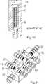
mit Zuleitungen und Verteilern in einer Ansicht auf die Ein- und Auslässe von Gas und Öl und schräg von oben,with supply lines and distributors in a view of the inlets and outlets of gas and oil and diagonally from above,
Bei der Anordnung nach den
Die unteren Ein- und Auslässe
In entsprechender Weise sind die oberen Ein- und Auslässe
Der in den
Im Folgenden wird der Verteiler
Der Verteiler
Zur weiteren Verbesserung der Vergleichmäßigung der Strömung und zum Verhindern einer Rückströmung des Öls sind zusätzlich Scheiben
Bei der Entladung, also der Entleerung der Gasdruckbehälter und der Abgabe des Gases an den Verbraucher drückt ein in der Zeichnung nicht dargestelltes Hydraulikaggregat Hydrauliköl in den Verteiler
Ein Gascontainer enthält in der Regel mehrere Sektionen, also Abteilungen mit Gasdruckbehältern, die über jeweils einen Gas- und einen Ölverteiler miteinander verbunden sind.A gas container usually contains several sections, so departments with gas pressure vessels, which are connected to each other via a gas and an oil distributor.
Nach dem Entleeren der ersten Sektion werden die oberen Ventile
In der Praxis hat sich gezeigt, dass trotz der notwendigerweise unsymmetrischen Anordnung der Leitungsführung durch die spezielle Gestaltung des Verteilers eine ausreichend gleichmäßige Strömung erreicht wird, so dass die Behälter jeder Sektion gleichmäßig entladen werden und der Ölstand in jedem der Behälter einer Sektion zu jedem Zeitpunkt auf praktisch gleichen Niveau steht.In practice, it has been found that despite the necessarily asymmetrical arrangement of the conduit by the special design of the manifold, a sufficiently uniform flow is achieved so that the vessels of each section are uniformly discharged and the oil level in each of the vessels of a section at any one time is practically the same level.
Die Erfindung ermöglicht eine von der Umgebung freie Positionierung der Behälter. So können auf die geometrischen Besonderheiten der Behälter (Länge, Durchmesser, Lage) und auf die Gegebenheiten des Fahrzeugs (Innenmaße, Einbauten usw.) angepasst die Rohrleitungen verlegt werden.The invention enables an environment-free positioning of the container. Thus, the pipelines can be laid according to the geometric characteristics of the containers (length, diameter, position) and to the conditions of the vehicle (internal dimensions, installations, etc.).
Die Erfindung gestattet auf die Rückstromzeit Einfluss zu nehmen. Durch die Wahl der Drosselelemente kann die Rückstromzeit verlängert oder verkürzt werden. Eine abgestimmte Verlängerung kann im Hinblick auf Verhinderung von Kondensat- oder Eisbildung vorteilhaft werden.The invention allows to influence the backflow time. By choosing the throttle elements, the return current time can be extended or shortened. A tuned extension may be advantageous in preventing condensation or icing.
Die Erfindung gestattet auf den Gasaustritt Einfluss zu nehmen. Durch die Wahl der Drosselelemente kann der Gas-Volumenstrom eingestellt werden. Eine Abstimmung kann beim Überströmen in ein tieferes Druckniveau von Bedeutung sein.The invention allows to exert influence on the gas outlet. By selecting the throttle elements, the gas flow rate can be adjusted. Tuning may be important when overflowing to a lower pressure level.
Die Erfindung gestattet auch eine beschleunigte Befüllung eines oder mehrere Behälter. Umgekehrt können Behälter gezielt mit geringeren Volumenströmen versorgt werden. Dieser Umstand kann z.B. bei einer Instrumentierung (Anfrage der Zustandsparameter) bedeutsam werden, z. B. Füllstandsabfrage an Behälter mit größter Zuströmung.The invention also permits accelerated filling of one or more containers. Conversely, containers can be specifically supplied with lower volume flows. This circumstance may e.g. in an instrumentation (request the condition parameters) become significant, z. B. level detection on containers with maximum inflow.
Die Anzahl der angeschlossenen Behälter einer Sektion kann frei gewählt werden, nicht zwingend ganzzahlig, nicht zwingend nach Zweierpotenz. Das Ausführungsbeispiel zeigt neun Behälteranschlüsse. Es sind sieben Behälter angeschlossen. Je nach Erfordernis kann kurzfristig jede beliebige Behälterzahl (in diesem Beispiel bis neun) eingerichtet werden. Eine größere Behälterzahl oberhalb von neun ist ebenfalls möglich. Die Gleichverteilung ist nicht negativ betroffen. The number of connected containers of a section can be freely selected, not necessarily integer, not necessarily to power of two. The embodiment shows nine container connections. There are seven containers connected. Depending on requirements, any number of containers (in this example up to nine) can be set up at short notice. A larger number of containers above nine is also possible. The equal distribution is not negatively affected.
BezugszeichenlisteLIST OF REFERENCE NUMBERS
(in Klammern stehen ggfs. die konkreten Bezeichnungen aus der Beschreibung des Ausführungsbeispiels)(in brackets are possibly the concrete terms from the description of the embodiment)
BezugszeichenlisteLIST OF REFERENCE NUMBERS
- 11
- Druckbehälterpressure vessel
- 22
- unterer Ein- und Auslass für Hydrauliköllower inlet and outlet for hydraulic oil
- 2a, 2b2a, 2b
- VentilValve
- 33
- oberer Ein- und Auslass für das Gasupper inlet and outlet for the gas
- 44
- ersten Leitungenfirst lines
- 55
- zweiten Leitungensecond lines
- 66
- Verteilerdistributor
- 77
- zweiter Verteilersecond distributor
- 1010
- erstes Drosselelement (Rohr)first throttle element (pipe)
- 1111
- hydraulikseitiger Anschluss des VerteilersHydraulic-side connection of the distributor
- 1212
- Durchbrechungen (axial verlaufende Längsschlitze)Breakthroughs (axial longitudinal slots)
- 1313
- behälterseitiger Anschluss des VerteilersTank-side connection of the distributor
- 1616
- Verteilergehäusedistributor housing
- 1717
- Scheibe als drittes DrosselelementDisc as the third throttle element
- 1818
- Durchbrechung (Schlitz)Breakthrough (slot)
- 2020
- Innenwand innerhalb des Verteilers
6 als zweites DrosselelementInner wall inside thedistributor 6 as a second throttle element - 2121
- erster Teilraumfirst subspace
- 2222
- zweiter Teilraumsecond subspace
- 2323
- DurchlassöffnungPort
ZITATE ENTHALTEN IN DER BESCHREIBUNG QUOTES INCLUDE IN THE DESCRIPTION
Diese Liste der vom Anmelder aufgeführten Dokumente wurde automatisiert erzeugt und ist ausschließlich zur besseren Information des Lesers aufgenommen. Die Liste ist nicht Bestandteil der deutschen Patent- bzw. Gebrauchsmusteranmeldung. Das DPMA übernimmt keinerlei Haftung für etwaige Fehler oder Auslassungen.This list of the documents listed by the applicant has been generated automatically and is included solely for the better information of the reader. The list is not part of the German patent or utility model application. The DPMA assumes no liability for any errors or omissions.
Zitierte PatentliteraturCited patent literature
- EP 1373786 B1[0010]EP 1373786 B1[0010]
- US 6652243 B2[0010]US 6652243 B2[0010]
Claims (6)
Translated fromGermanPriority Applications (2)
| Application Number | Priority Date | Filing Date | Title |
|---|---|---|---|
| DE201310106532DE102013106532A1 (en) | 2013-06-21 | 2013-06-21 | Gas container with several pressure vessels |
| PCT/EP2014/062820WO2014202663A1 (en) | 2013-06-21 | 2014-06-18 | Gas container comprising multiple pressure vessels |
Applications Claiming Priority (1)
| Application Number | Priority Date | Filing Date | Title |
|---|---|---|---|
| DE201310106532DE102013106532A1 (en) | 2013-06-21 | 2013-06-21 | Gas container with several pressure vessels |
Publications (1)
| Publication Number | Publication Date |
|---|---|
| DE102013106532A1true DE102013106532A1 (en) | 2015-01-08 |
Family
ID=51033157
Family Applications (1)
| Application Number | Title | Priority Date | Filing Date |
|---|---|---|---|
| DE201310106532CeasedDE102013106532A1 (en) | 2013-06-21 | 2013-06-21 | Gas container with several pressure vessels |
Country Status (2)
| Country | Link |
|---|---|
| DE (1) | DE102013106532A1 (en) |
| WO (1) | WO2014202663A1 (en) |
Cited By (2)
| Publication number | Priority date | Publication date | Assignee | Title |
|---|---|---|---|---|
| EP4560181A1 (en)* | 2023-11-22 | 2025-05-28 | Robert Bosch GmbH | Manifold and high-pressure h2-system |
| EP4560180A1 (en)* | 2023-11-21 | 2025-05-28 | Robert Bosch GmbH | Manifold and high-pressure h2-system |
Citations (8)
| Publication number | Priority date | Publication date | Assignee | Title |
|---|---|---|---|---|
| US4750869A (en)* | 1984-05-09 | 1988-06-14 | Booster Technologies, Inc. | Method and apparatus for boosting gas from a low-pressure source to a high-pressure receptacle |
| DE19843669C1 (en)* | 1998-09-23 | 2000-03-16 | Hermann Josef Winter | Tap installation for filling gas tank with methane has gas accumulator and emission device for feeding gas into tank |
| US6652243B2 (en) | 2001-08-23 | 2003-11-25 | Neogas Inc. | Method and apparatus for filling a storage vessel with compressed gas |
| EP1373786B1 (en) | 2001-03-16 | 2009-07-22 | Neogas Inc | Compressed natural gas dispensing system |
| US20090294470A1 (en)* | 2008-05-27 | 2009-12-03 | Neogas Inc. | Variable Frequency Drive for Gas Dispensing System |
| US20100163135A1 (en)* | 2007-09-12 | 2010-07-01 | Hygen Sia | Method for compressing gaseous fuel for fuelling vehicle and device for implementation thereof |
| US20100320224A1 (en)* | 2009-02-10 | 2010-12-23 | Neogas Inc. | System for Avoiding Excessive Pressure while Discharging Compressed Gas Cylinders |
| US20120130549A1 (en)* | 2009-02-11 | 2012-05-24 | Nel Hydrogen As | Plant for storing and supplying compressed gas |
Family Cites Families (3)
| Publication number | Priority date | Publication date | Assignee | Title |
|---|---|---|---|---|
| CA788175A (en)* | 1963-12-20 | 1968-06-25 | D. Lewis John | Method and apparatus for handling natural gas |
| NO148481C (en)* | 1980-07-08 | 1983-10-19 | Moss Rosenberg Verft As | PROCEDURE FOR TRANSPORTING OIL AND GAS UNDER HIGH PRESSURE IN TANKER ON BOARD OF A SHIP |
| US5454408A (en)* | 1993-08-11 | 1995-10-03 | Thermo Power Corporation | Variable-volume storage and dispensing apparatus for compressed natural gas |
- 2013
- 2013-06-21DEDE201310106532patent/DE102013106532A1/ennot_activeCeased
- 2014
- 2014-06-18WOPCT/EP2014/062820patent/WO2014202663A1/enactiveApplication Filing
Patent Citations (8)
| Publication number | Priority date | Publication date | Assignee | Title |
|---|---|---|---|---|
| US4750869A (en)* | 1984-05-09 | 1988-06-14 | Booster Technologies, Inc. | Method and apparatus for boosting gas from a low-pressure source to a high-pressure receptacle |
| DE19843669C1 (en)* | 1998-09-23 | 2000-03-16 | Hermann Josef Winter | Tap installation for filling gas tank with methane has gas accumulator and emission device for feeding gas into tank |
| EP1373786B1 (en) | 2001-03-16 | 2009-07-22 | Neogas Inc | Compressed natural gas dispensing system |
| US6652243B2 (en) | 2001-08-23 | 2003-11-25 | Neogas Inc. | Method and apparatus for filling a storage vessel with compressed gas |
| US20100163135A1 (en)* | 2007-09-12 | 2010-07-01 | Hygen Sia | Method for compressing gaseous fuel for fuelling vehicle and device for implementation thereof |
| US20090294470A1 (en)* | 2008-05-27 | 2009-12-03 | Neogas Inc. | Variable Frequency Drive for Gas Dispensing System |
| US20100320224A1 (en)* | 2009-02-10 | 2010-12-23 | Neogas Inc. | System for Avoiding Excessive Pressure while Discharging Compressed Gas Cylinders |
| US20120130549A1 (en)* | 2009-02-11 | 2012-05-24 | Nel Hydrogen As | Plant for storing and supplying compressed gas |
Cited By (3)
| Publication number | Priority date | Publication date | Assignee | Title |
|---|---|---|---|---|
| EP4560180A1 (en)* | 2023-11-21 | 2025-05-28 | Robert Bosch GmbH | Manifold and high-pressure h2-system |
| WO2025108678A1 (en)* | 2023-11-21 | 2025-05-30 | Robert Bosch Gmbh | Distributor and h2 high-pressure system |
| EP4560181A1 (en)* | 2023-11-22 | 2025-05-28 | Robert Bosch GmbH | Manifold and high-pressure h2-system |
Also Published As
| Publication number | Publication date |
|---|---|
| WO2014202663A1 (en) | 2014-12-24 |
Similar Documents
| Publication | Publication Date | Title |
|---|---|---|
| EP2369242B1 (en) | Pressure equalising device for systems through which fluid flows | |
| DE102018000756A1 (en) | Compressed gas tank and compressed gas storage | |
| WO2019233677A1 (en) | Tank device for the temperature pressure relief of a fuel cell tank | |
| EP2472211B1 (en) | Heat exchange device | |
| EP2959208B1 (en) | Pressure vessel comprising a heat exchanger for a cryogenically stored medium | |
| DE2549367B2 (en) | Device for relieving pressure surges in a pipeline for liquids | |
| DE102018010103A1 (en) | Ringtank | |
| DE102009014984A1 (en) | Pneumatic feeding system for supplying alumina to aluminum smelter from storage tank, has fluidizing gas pipe exhibiting passage-wall openings for passage of fluidizing gases and designed as continuous pipe in area of discharge pipes | |
| WO2021018563A1 (en) | Pressurized-container arrangement | |
| DE102013106532A1 (en) | Gas container with several pressure vessels | |
| DE102007049458A1 (en) | Compressed gas installation for storing a gas comprises compressed gas containers for holding a pressurized gas within a gas volume, a liquid container for holding an equalization liquid and a pump unit connected to liquid openings | |
| WO2013023711A1 (en) | Device for filtering and separating flow media by means of membranes | |
| DE2159963C3 (en) | Cavitation-reducing throttle device | |
| AT514205B1 (en) | Method for damping pressure pulsations | |
| DE2435018A1 (en) | DOSING DEVICE FOR CENTRAL LUBRICATION SYSTEMS | |
| DE19958960A1 (en) | Changeover panel between drink containers and filling equipment in drinks industry | |
| DE202015101027U1 (en) | Connector with two flanges for connection of water treatment devices and associated connection arrangement | |
| DE102012002526A1 (en) | Liquid distributor for distributing liquid to e.g. tube bundle in heat exchanger and material exchange column, has through holes assigned with conduit tube such that liquid located in distribution container is discharged through tube | |
| DE102008039213B4 (en) | Filter device for vacuum pumps | |
| DE102010050576B4 (en) | A collection unit for dispensing liquids from at least one tank and tanker | |
| DE20007262U1 (en) | Steam injector | |
| DE1756591C3 (en) | Device for the hydraulic conveyance of solids | |
| DE102020128254B4 (en) | distributor bar | |
| DE102012206017A1 (en) | Device for mixing bulk material in mixing system, has mixing chamber and mixing bypass pipes having gas ports for connection to gas source | |
| DE366357C (en) | Control for systems for filling liquids, in particular flammable liquids, by means of a pressurized protective gas |
Legal Events
| Date | Code | Title | Description |
|---|---|---|---|
| R012 | Request for examination validly filed | ||
| R016 | Response to examination communication | ||
| R002 | Refusal decision in examination/registration proceedings | ||
| R003 | Refusal decision now final |