DE102013102451A1 - Spreadable implant for the spine - Google Patents
Spreadable implant for the spineDownload PDFInfo
- Publication number
- DE102013102451A1 DE102013102451A1DE201310102451DE102013102451ADE102013102451A1DE 102013102451 A1DE102013102451 A1DE 102013102451A1DE 201310102451DE201310102451DE 201310102451DE 102013102451 ADE102013102451 ADE 102013102451ADE 102013102451 A1DE102013102451 A1DE 102013102451A1
- Authority
- DE
- Germany
- Prior art keywords
- implant
- operating instrument
- threaded
- instrument
- shaft
- Prior art date
- Legal status (The legal status is an assumption and is not a legal conclusion. Google has not performed a legal analysis and makes no representation as to the accuracy of the status listed.)
- Withdrawn
Links
- 239000007943implantSubstances0.000titleclaimsabstractdescription106
- 230000007480spreadingEffects0.000claimsabstractdescription23
- 238000004873anchoringMethods0.000claimsabstractdescription7
- 230000005540biological transmissionEffects0.000claimsdescription12
- 230000008878couplingEffects0.000claimsdescription5
- 238000010168coupling processMethods0.000claimsdescription5
- 238000005859coupling reactionMethods0.000claimsdescription5
- 239000003795chemical substances by applicationSubstances0.000claims2
- 230000033001locomotionEffects0.000description12
- 210000000988bone and boneAnatomy0.000description9
- 239000000463materialSubstances0.000description7
- 230000007246mechanismEffects0.000description7
- 238000000034methodMethods0.000description6
- 238000012937correctionMethods0.000description5
- 230000007547defectEffects0.000description5
- 210000000115thoracic cavityAnatomy0.000description4
- 230000008901benefitEffects0.000description3
- 238000013461designMethods0.000description3
- 239000012634fragmentSubstances0.000description3
- 238000002513implantationMethods0.000description3
- 210000000278spinal cordAnatomy0.000description3
- 206010041569spinal fractureDiseases0.000description3
- 208000007623LordosisDiseases0.000description2
- 208000001132OsteoporosisDiseases0.000description2
- 239000004696Poly ether ether ketoneSubstances0.000description2
- 230000003187abdominal effectEffects0.000description2
- 238000013459approachMethods0.000description2
- 230000006378damageEffects0.000description2
- 238000003780insertionMethods0.000description2
- 230000037431insertionEffects0.000description2
- 229920002530polyetherether ketonePolymers0.000description2
- 239000010936titaniumSubstances0.000description2
- BUHVIAUBTBOHAG-FOYDDCNASA-N(2r,3r,4s,5r)-2-[6-[[2-(3,5-dimethoxyphenyl)-2-(2-methylphenyl)ethyl]amino]purin-9-yl]-5-(hydroxymethyl)oxolane-3,4-diolChemical compoundCOC1=CC(OC)=CC(C(CNC=2C=3N=CN(C=3N=CN=2)[C@H]2[C@@H]([C@H](O)[C@@H](CO)O2)O)C=2C(=CC=CC=2)C)=C1BUHVIAUBTBOHAG-FOYDDCNASA-N0.000description1
- 206010010356Congenital anomalyDiseases0.000description1
- 206010023509KyphosisDiseases0.000description1
- 206010028980NeoplasmDiseases0.000description1
- 208000020307Spinal diseaseDiseases0.000description1
- -1Ti 6 Al 4Chemical compound0.000description1
- 229910001069Ti alloyInorganic materials0.000description1
- RTAQQCXQSZGOHL-UHFFFAOYSA-NTitaniumChemical compound[Ti]RTAQQCXQSZGOHL-UHFFFAOYSA-N0.000description1
- 210000000683abdominal cavityAnatomy0.000description1
- 230000001154acute effectEffects0.000description1
- 238000005452bendingMethods0.000description1
- 239000008280bloodSubstances0.000description1
- 210000004369bloodAnatomy0.000description1
- 230000008468bone growthEffects0.000description1
- 239000000316bone substituteSubstances0.000description1
- 210000000481breastAnatomy0.000description1
- 229910000389calcium phosphateInorganic materials0.000description1
- 239000001506calcium phosphateSubstances0.000description1
- 235000011010calcium phosphatesNutrition0.000description1
- 159000000007calcium saltsChemical class0.000description1
- 201000011510cancerDiseases0.000description1
- 230000008859changeEffects0.000description1
- 230000006735deficitEffects0.000description1
- 230000003412degenerative effectEffects0.000description1
- 238000005553drillingMethods0.000description1
- 239000012530fluidSubstances0.000description1
- 238000002594fluoroscopyMethods0.000description1
- 230000004927fusionEffects0.000description1
- 230000012010growthEffects0.000description1
- 230000035876healingEffects0.000description1
- 238000003384imaging methodMethods0.000description1
- 208000015181infectious diseaseDiseases0.000description1
- 238000009434installationMethods0.000description1
- 230000003993interactionEffects0.000description1
- 230000007775lateEffects0.000description1
- 239000007788liquidSubstances0.000description1
- 210000004705lumbosacral regionAnatomy0.000description1
- 230000036244malformationEffects0.000description1
- 230000013011matingEffects0.000description1
- HLXZNVUGXRDIFK-UHFFFAOYSA-Nnickel titaniumChemical compound[Ti].[Ti].[Ti].[Ti].[Ti].[Ti].[Ti].[Ti].[Ti].[Ti].[Ti].[Ni].[Ni].[Ni].[Ni].[Ni].[Ni].[Ni].[Ni].[Ni].[Ni].[Ni].[Ni].[Ni].[Ni]HLXZNVUGXRDIFK-UHFFFAOYSA-N0.000description1
- 229910001000nickel titaniumInorganic materials0.000description1
- 239000004033plasticSubstances0.000description1
- 238000002360preparation methodMethods0.000description1
- 230000008569processEffects0.000description1
- 230000009467reductionEffects0.000description1
- 239000011347resinSubstances0.000description1
- 229920005989resinPolymers0.000description1
- 230000002441reversible effectEffects0.000description1
- 125000006850spacer groupChemical group0.000description1
- 230000006641stabilisationEffects0.000description1
- 238000011105stabilizationMethods0.000description1
- 230000003068static effectEffects0.000description1
- 238000001356surgical procedureMethods0.000description1
- 229910052715tantalumInorganic materials0.000description1
- GUVRBAGPIYLISA-UHFFFAOYSA-Ntantalum atomChemical compound[Ta]GUVRBAGPIYLISA-UHFFFAOYSA-N0.000description1
- 210000001519tissueAnatomy0.000description1
- 229910052719titaniumInorganic materials0.000description1
- 238000012546transferMethods0.000description1
- QORWJWZARLRLPR-UHFFFAOYSA-Htricalcium bis(phosphate)Chemical compound[Ca+2].[Ca+2].[Ca+2].[O-]P([O-])([O-])=O.[O-]P([O-])([O-])=OQORWJWZARLRLPR-UHFFFAOYSA-H0.000description1
Images


Classifications
- A—HUMAN NECESSITIES
- A61—MEDICAL OR VETERINARY SCIENCE; HYGIENE
- A61F—FILTERS IMPLANTABLE INTO BLOOD VESSELS; PROSTHESES; DEVICES PROVIDING PATENCY TO, OR PREVENTING COLLAPSING OF, TUBULAR STRUCTURES OF THE BODY, e.g. STENTS; ORTHOPAEDIC, NURSING OR CONTRACEPTIVE DEVICES; FOMENTATION; TREATMENT OR PROTECTION OF EYES OR EARS; BANDAGES, DRESSINGS OR ABSORBENT PADS; FIRST-AID KITS
- A61F2/00—Filters implantable into blood vessels; Prostheses, i.e. artificial substitutes or replacements for parts of the body; Appliances for connecting them with the body; Devices providing patency to, or preventing collapsing of, tubular structures of the body, e.g. stents
- A61F2/02—Prostheses implantable into the body
- A61F2/30—Joints
- A61F2/44—Joints for the spine, e.g. vertebrae, spinal discs
- A61F2/4455—Joints for the spine, e.g. vertebrae, spinal discs for the fusion of spinal bodies, e.g. intervertebral fusion of adjacent spinal bodies, e.g. fusion cages
- A61F2/4465—Joints for the spine, e.g. vertebrae, spinal discs for the fusion of spinal bodies, e.g. intervertebral fusion of adjacent spinal bodies, e.g. fusion cages having a circular or kidney shaped cross-section substantially perpendicular to the axis of the spine
- A—HUMAN NECESSITIES
- A61—MEDICAL OR VETERINARY SCIENCE; HYGIENE
- A61F—FILTERS IMPLANTABLE INTO BLOOD VESSELS; PROSTHESES; DEVICES PROVIDING PATENCY TO, OR PREVENTING COLLAPSING OF, TUBULAR STRUCTURES OF THE BODY, e.g. STENTS; ORTHOPAEDIC, NURSING OR CONTRACEPTIVE DEVICES; FOMENTATION; TREATMENT OR PROTECTION OF EYES OR EARS; BANDAGES, DRESSINGS OR ABSORBENT PADS; FIRST-AID KITS
- A61F2/00—Filters implantable into blood vessels; Prostheses, i.e. artificial substitutes or replacements for parts of the body; Appliances for connecting them with the body; Devices providing patency to, or preventing collapsing of, tubular structures of the body, e.g. stents
- A61F2/02—Prostheses implantable into the body
- A61F2/30—Joints
- A61F2/44—Joints for the spine, e.g. vertebrae, spinal discs
- A61F2/442—Intervertebral or spinal discs, e.g. resilient
- A—HUMAN NECESSITIES
- A61—MEDICAL OR VETERINARY SCIENCE; HYGIENE
- A61F—FILTERS IMPLANTABLE INTO BLOOD VESSELS; PROSTHESES; DEVICES PROVIDING PATENCY TO, OR PREVENTING COLLAPSING OF, TUBULAR STRUCTURES OF THE BODY, e.g. STENTS; ORTHOPAEDIC, NURSING OR CONTRACEPTIVE DEVICES; FOMENTATION; TREATMENT OR PROTECTION OF EYES OR EARS; BANDAGES, DRESSINGS OR ABSORBENT PADS; FIRST-AID KITS
- A61F2/00—Filters implantable into blood vessels; Prostheses, i.e. artificial substitutes or replacements for parts of the body; Appliances for connecting them with the body; Devices providing patency to, or preventing collapsing of, tubular structures of the body, e.g. stents
- A61F2/02—Prostheses implantable into the body
- A61F2/30—Joints
- A61F2/46—Special tools for implanting artificial joints
- A61F2/4603—Special tools for implanting artificial joints for insertion or extraction of endoprosthetic joints or of accessories thereof
- A61F2/4611—Special tools for implanting artificial joints for insertion or extraction of endoprosthetic joints or of accessories thereof of spinal prostheses
- A—HUMAN NECESSITIES
- A61—MEDICAL OR VETERINARY SCIENCE; HYGIENE
- A61F—FILTERS IMPLANTABLE INTO BLOOD VESSELS; PROSTHESES; DEVICES PROVIDING PATENCY TO, OR PREVENTING COLLAPSING OF, TUBULAR STRUCTURES OF THE BODY, e.g. STENTS; ORTHOPAEDIC, NURSING OR CONTRACEPTIVE DEVICES; FOMENTATION; TREATMENT OR PROTECTION OF EYES OR EARS; BANDAGES, DRESSINGS OR ABSORBENT PADS; FIRST-AID KITS
- A61F2/00—Filters implantable into blood vessels; Prostheses, i.e. artificial substitutes or replacements for parts of the body; Appliances for connecting them with the body; Devices providing patency to, or preventing collapsing of, tubular structures of the body, e.g. stents
- A61F2/02—Prostheses implantable into the body
- A61F2/30—Joints
- A61F2002/30001—Additional features of subject-matter classified in A61F2/28, A61F2/30 and subgroups thereof
- A61F2002/30316—The prosthesis having different structural features at different locations within the same prosthesis; Connections between prosthetic parts; Special structural features of bone or joint prostheses not otherwise provided for
- A61F2002/30329—Connections or couplings between prosthetic parts, e.g. between modular parts; Connecting elements
- A61F2002/30405—Connections or couplings between prosthetic parts, e.g. between modular parts; Connecting elements made by screwing complementary threads machined on the parts themselves
- A—HUMAN NECESSITIES
- A61—MEDICAL OR VETERINARY SCIENCE; HYGIENE
- A61F—FILTERS IMPLANTABLE INTO BLOOD VESSELS; PROSTHESES; DEVICES PROVIDING PATENCY TO, OR PREVENTING COLLAPSING OF, TUBULAR STRUCTURES OF THE BODY, e.g. STENTS; ORTHOPAEDIC, NURSING OR CONTRACEPTIVE DEVICES; FOMENTATION; TREATMENT OR PROTECTION OF EYES OR EARS; BANDAGES, DRESSINGS OR ABSORBENT PADS; FIRST-AID KITS
- A61F2/00—Filters implantable into blood vessels; Prostheses, i.e. artificial substitutes or replacements for parts of the body; Appliances for connecting them with the body; Devices providing patency to, or preventing collapsing of, tubular structures of the body, e.g. stents
- A61F2/02—Prostheses implantable into the body
- A61F2/30—Joints
- A61F2002/30001—Additional features of subject-matter classified in A61F2/28, A61F2/30 and subgroups thereof
- A61F2002/30316—The prosthesis having different structural features at different locations within the same prosthesis; Connections between prosthetic parts; Special structural features of bone or joint prostheses not otherwise provided for
- A61F2002/30329—Connections or couplings between prosthetic parts, e.g. between modular parts; Connecting elements
- A61F2002/30518—Connections or couplings between prosthetic parts, e.g. between modular parts; Connecting elements with possibility of relative movement between the prosthetic parts
- A61F2002/30523—Connections or couplings between prosthetic parts, e.g. between modular parts; Connecting elements with possibility of relative movement between the prosthetic parts by means of meshing gear teeth
- A—HUMAN NECESSITIES
- A61—MEDICAL OR VETERINARY SCIENCE; HYGIENE
- A61F—FILTERS IMPLANTABLE INTO BLOOD VESSELS; PROSTHESES; DEVICES PROVIDING PATENCY TO, OR PREVENTING COLLAPSING OF, TUBULAR STRUCTURES OF THE BODY, e.g. STENTS; ORTHOPAEDIC, NURSING OR CONTRACEPTIVE DEVICES; FOMENTATION; TREATMENT OR PROTECTION OF EYES OR EARS; BANDAGES, DRESSINGS OR ABSORBENT PADS; FIRST-AID KITS
- A61F2/00—Filters implantable into blood vessels; Prostheses, i.e. artificial substitutes or replacements for parts of the body; Appliances for connecting them with the body; Devices providing patency to, or preventing collapsing of, tubular structures of the body, e.g. stents
- A61F2/02—Prostheses implantable into the body
- A61F2/30—Joints
- A61F2002/30001—Additional features of subject-matter classified in A61F2/28, A61F2/30 and subgroups thereof
- A61F2002/30316—The prosthesis having different structural features at different locations within the same prosthesis; Connections between prosthetic parts; Special structural features of bone or joint prostheses not otherwise provided for
- A61F2002/30535—Special structural features of bone or joint prostheses not otherwise provided for
- A61F2002/30537—Special structural features of bone or joint prostheses not otherwise provided for adjustable
- A61F2002/30556—Special structural features of bone or joint prostheses not otherwise provided for adjustable for adjusting thickness
- A—HUMAN NECESSITIES
- A61—MEDICAL OR VETERINARY SCIENCE; HYGIENE
- A61F—FILTERS IMPLANTABLE INTO BLOOD VESSELS; PROSTHESES; DEVICES PROVIDING PATENCY TO, OR PREVENTING COLLAPSING OF, TUBULAR STRUCTURES OF THE BODY, e.g. STENTS; ORTHOPAEDIC, NURSING OR CONTRACEPTIVE DEVICES; FOMENTATION; TREATMENT OR PROTECTION OF EYES OR EARS; BANDAGES, DRESSINGS OR ABSORBENT PADS; FIRST-AID KITS
- A61F2/00—Filters implantable into blood vessels; Prostheses, i.e. artificial substitutes or replacements for parts of the body; Appliances for connecting them with the body; Devices providing patency to, or preventing collapsing of, tubular structures of the body, e.g. stents
- A61F2/02—Prostheses implantable into the body
- A61F2/30—Joints
- A61F2002/30001—Additional features of subject-matter classified in A61F2/28, A61F2/30 and subgroups thereof
- A61F2002/30316—The prosthesis having different structural features at different locations within the same prosthesis; Connections between prosthetic parts; Special structural features of bone or joint prostheses not otherwise provided for
- A61F2002/30535—Special structural features of bone or joint prostheses not otherwise provided for
- A61F2002/30579—Special structural features of bone or joint prostheses not otherwise provided for with mechanically expandable devices, e.g. fixation devices
- A—HUMAN NECESSITIES
- A61—MEDICAL OR VETERINARY SCIENCE; HYGIENE
- A61F—FILTERS IMPLANTABLE INTO BLOOD VESSELS; PROSTHESES; DEVICES PROVIDING PATENCY TO, OR PREVENTING COLLAPSING OF, TUBULAR STRUCTURES OF THE BODY, e.g. STENTS; ORTHOPAEDIC, NURSING OR CONTRACEPTIVE DEVICES; FOMENTATION; TREATMENT OR PROTECTION OF EYES OR EARS; BANDAGES, DRESSINGS OR ABSORBENT PADS; FIRST-AID KITS
- A61F2/00—Filters implantable into blood vessels; Prostheses, i.e. artificial substitutes or replacements for parts of the body; Appliances for connecting them with the body; Devices providing patency to, or preventing collapsing of, tubular structures of the body, e.g. stents
- A61F2/02—Prostheses implantable into the body
- A61F2/30—Joints
- A61F2002/30001—Additional features of subject-matter classified in A61F2/28, A61F2/30 and subgroups thereof
- A61F2002/30316—The prosthesis having different structural features at different locations within the same prosthesis; Connections between prosthetic parts; Special structural features of bone or joint prostheses not otherwise provided for
- A61F2002/30535—Special structural features of bone or joint prostheses not otherwise provided for
- A61F2002/30601—Special structural features of bone or joint prostheses not otherwise provided for telescopic
- A—HUMAN NECESSITIES
- A61—MEDICAL OR VETERINARY SCIENCE; HYGIENE
- A61F—FILTERS IMPLANTABLE INTO BLOOD VESSELS; PROSTHESES; DEVICES PROVIDING PATENCY TO, OR PREVENTING COLLAPSING OF, TUBULAR STRUCTURES OF THE BODY, e.g. STENTS; ORTHOPAEDIC, NURSING OR CONTRACEPTIVE DEVICES; FOMENTATION; TREATMENT OR PROTECTION OF EYES OR EARS; BANDAGES, DRESSINGS OR ABSORBENT PADS; FIRST-AID KITS
- A61F2/00—Filters implantable into blood vessels; Prostheses, i.e. artificial substitutes or replacements for parts of the body; Appliances for connecting them with the body; Devices providing patency to, or preventing collapsing of, tubular structures of the body, e.g. stents
- A61F2/02—Prostheses implantable into the body
- A61F2/30—Joints
- A61F2/30767—Special external or bone-contacting surface, e.g. coating for improving bone ingrowth
- A61F2/30771—Special external or bone-contacting surface, e.g. coating for improving bone ingrowth applied in original prostheses, e.g. holes or grooves
- A61F2002/30772—Apertures or holes, e.g. of circular cross section
- A61F2002/30774—Apertures or holes, e.g. of circular cross section internally-threaded
- A—HUMAN NECESSITIES
- A61—MEDICAL OR VETERINARY SCIENCE; HYGIENE
- A61F—FILTERS IMPLANTABLE INTO BLOOD VESSELS; PROSTHESES; DEVICES PROVIDING PATENCY TO, OR PREVENTING COLLAPSING OF, TUBULAR STRUCTURES OF THE BODY, e.g. STENTS; ORTHOPAEDIC, NURSING OR CONTRACEPTIVE DEVICES; FOMENTATION; TREATMENT OR PROTECTION OF EYES OR EARS; BANDAGES, DRESSINGS OR ABSORBENT PADS; FIRST-AID KITS
- A61F2/00—Filters implantable into blood vessels; Prostheses, i.e. artificial substitutes or replacements for parts of the body; Appliances for connecting them with the body; Devices providing patency to, or preventing collapsing of, tubular structures of the body, e.g. stents
- A61F2/02—Prostheses implantable into the body
- A61F2/30—Joints
- A61F2/30767—Special external or bone-contacting surface, e.g. coating for improving bone ingrowth
- A61F2/30771—Special external or bone-contacting surface, e.g. coating for improving bone ingrowth applied in original prostheses, e.g. holes or grooves
- A61F2002/30772—Apertures or holes, e.g. of circular cross section
- A61F2002/30784—Plurality of holes
- A—HUMAN NECESSITIES
- A61—MEDICAL OR VETERINARY SCIENCE; HYGIENE
- A61F—FILTERS IMPLANTABLE INTO BLOOD VESSELS; PROSTHESES; DEVICES PROVIDING PATENCY TO, OR PREVENTING COLLAPSING OF, TUBULAR STRUCTURES OF THE BODY, e.g. STENTS; ORTHOPAEDIC, NURSING OR CONTRACEPTIVE DEVICES; FOMENTATION; TREATMENT OR PROTECTION OF EYES OR EARS; BANDAGES, DRESSINGS OR ABSORBENT PADS; FIRST-AID KITS
- A61F2/00—Filters implantable into blood vessels; Prostheses, i.e. artificial substitutes or replacements for parts of the body; Appliances for connecting them with the body; Devices providing patency to, or preventing collapsing of, tubular structures of the body, e.g. stents
- A61F2/02—Prostheses implantable into the body
- A61F2/30—Joints
- A61F2/30767—Special external or bone-contacting surface, e.g. coating for improving bone ingrowth
- A61F2/30771—Special external or bone-contacting surface, e.g. coating for improving bone ingrowth applied in original prostheses, e.g. holes or grooves
- A61F2002/30841—Sharp anchoring protrusions for impaction into the bone, e.g. sharp pins, spikes
- A61F2002/30843—Pyramidally-shaped
- A—HUMAN NECESSITIES
- A61—MEDICAL OR VETERINARY SCIENCE; HYGIENE
- A61F—FILTERS IMPLANTABLE INTO BLOOD VESSELS; PROSTHESES; DEVICES PROVIDING PATENCY TO, OR PREVENTING COLLAPSING OF, TUBULAR STRUCTURES OF THE BODY, e.g. STENTS; ORTHOPAEDIC, NURSING OR CONTRACEPTIVE DEVICES; FOMENTATION; TREATMENT OR PROTECTION OF EYES OR EARS; BANDAGES, DRESSINGS OR ABSORBENT PADS; FIRST-AID KITS
- A61F2/00—Filters implantable into blood vessels; Prostheses, i.e. artificial substitutes or replacements for parts of the body; Appliances for connecting them with the body; Devices providing patency to, or preventing collapsing of, tubular structures of the body, e.g. stents
- A61F2/02—Prostheses implantable into the body
- A61F2/30—Joints
- A61F2/46—Special tools for implanting artificial joints
- A61F2/4603—Special tools for implanting artificial joints for insertion or extraction of endoprosthetic joints or of accessories thereof
- A61F2002/4625—Special tools for implanting artificial joints for insertion or extraction of endoprosthetic joints or of accessories thereof with relative movement between parts of the instrument during use
- A61F2002/4627—Special tools for implanting artificial joints for insertion or extraction of endoprosthetic joints or of accessories thereof with relative movement between parts of the instrument during use with linear motion along or rotating motion about the instrument axis or the implantation direction, e.g. telescopic, along a guiding rod, screwing inside the instrument
Landscapes
- Health & Medical Sciences (AREA)
- Engineering & Computer Science (AREA)
- Biomedical Technology (AREA)
- Orthopedic Medicine & Surgery (AREA)
- Neurology (AREA)
- Transplantation (AREA)
- Heart & Thoracic Surgery (AREA)
- Oral & Maxillofacial Surgery (AREA)
- Cardiology (AREA)
- Vascular Medicine (AREA)
- Life Sciences & Earth Sciences (AREA)
- Animal Behavior & Ethology (AREA)
- General Health & Medical Sciences (AREA)
- Public Health (AREA)
- Veterinary Medicine (AREA)
- Physical Education & Sports Medicine (AREA)
- Prostheses (AREA)
Abstract
Translated fromGermanDescription
Translated fromGermanDie vorliegende Erfindung betrifft ein aufspreizbares Implantat, insbesondere betrifft die Erfindung ein spreizbares höhenadaptierbares Implantat für die Lenden- und Brustwirbelsäule, das als Ersatz für Wirbelkörper und/oder Bandscheibenräume bei Versteifungsoperationen dienen kann.The present invention relates to an expandable implant, in particular, the invention relates to a spreadable height-adaptable implant for the lumbar and thoracic spine, which can serve as a replacement for vertebral bodies and / or disc spaces during stiffening operations.
Solche lumbalen und thoracalen Implantate werden zur interkorporalen Fusion (Versteifung der Wirbelkörper) eingesetzt. Prinzipiell ist jedoch auch eine intrakorporale Anwendung möglich.Such lumbar and thoracic implants are used for intercorporal fusion (stiffening of the vertebral bodies). In principle, however, an intracorporeal application is possible.
In der Konfiguration als Wirbelkörperersatz kann das Implantat bei Zerstörungen oder Formdefekten jeder Art eingesetzt werden: so bei Tumoren, Wirbelbrüchen, Spätfolgen nach Wirbelbrüchen sowie Infektionen oder angeborenen Fehlbildungen eines oder mehrerer Wirbelkörper.When configured as a vertebral body replacement, the implant can be used for destruction or shape defects of any kind: for tumors, vertebral fractures, late effects after vertebral fractures, as well as infections or congenital malformations of one or more vertebral bodies.
In der Konfiguration als Zwischenwirbelersatz, „intersomatischer Cage“ = „aufspreizbarer Cage“, kann das Implantat zur Wiederherstellung der vorderen Säule der Wirbelreihe im Rahmen von Versteifungseingriffen verwendet werden. Hier sind Anwendungsgebiete die degenerativen Wirbelsäulenerkrankungen, Segmentfehlstellungen und Segmentinstabilitäten verschiedenster Ursachen.When configured as intervertebral replacement, "intersomatic cage", the implant can be used to restore the anterior column of the vertebral column as part of stiffening procedures. Here are areas of application the degenerative spinal disorders, segmental malpositions and segmental instabilities of various causes.
Im Allgemeinen wird zunächst der Zwischenwirbelraum vom Rücken beziehungsweise vom Brust- oder Bauchraum her ausgeräumt, bei Wirbelkörperersatz der Wirbelkörper entfernt und dann das Implantat in den entstandenen Zwischenraum eingeführt, um zur Stellungskorrektur sowie als Abstandshalter zur mechanisch stabilen Verbindung zwischen den angrenzenden Wirbelsäulenabschnitten zu dienen.In general, first, the intervertebral space is cleared from the back or from the chest or abdominal cavity, vertebral body replacement removes the vertebral body, and then the implant is inserted into the resulting space to serve for positional correction and as a spacer for mechanically stable connection between the adjacent spinal column portions.
Es hat sich als vorteilhaft erwiesen, solche Implantate als „Cage“, das heißt in Form eines Käfigs, auszubilden, damit in dessen Innenraum beispielsweise Knochenmaterial oder Knochenersatzmaterialien zur Beschleunigung des Einheilens eingebracht werden können. Hierdurch kann die Fusion des Cages ermöglicht bzw. beschleunigt werden.It has proved to be advantageous to form such implants as "cages", that is to say in the form of a cage, so that, for example, bone material or bone substitute materials can be introduced into the interior thereof to accelerate the healing process. This allows the merger of Cages enabled or accelerated.
Über einen Spreizmechanismus nach dem Einbringen in den Wirbelsäulendefekt aufspreizbare Cages haben den Vorteil, technisch einfacher und für die Ankerwirbel schonender implantiert werden zu können:
durch das stufenlose Aufspreizen wird das Implantat einerseits fest verklemmt und fixiert. Andererseits erlaubt es individuelle Stellungskorrekturen der angrenzenden Wirbel, um normale geometrische Verhältnisse durch Schaffung von Lordose der Lendenwirbelsäule oder Korrektur einer vermehrten Brustkyphose wieder herzustellen.Spreadable cages via a spreading mechanism after introduction into the spinal defect have the advantage of being able to be implanted more gently and more gently for the anchor vertebrae:
Due to the continuous spreading, the implant is firmly clamped and fixed on the one hand. On the other hand, it allows individual posture corrections of adjacent vertebrae to restore normal geometric relationships by creating lumbar spine lordosis or correcting for increased breast kyphosis.
Mit Ausnahme des Einsatzes bei bösartigen Tumoren soll das Durchwachsen des Implantats bzw. des rekonstruierten Wirbelsäulenabschnitts mit körpereigenem Knochengewebe ermöglicht werden. Deshalb weisen solche Implantate vorzugsweise Durchbrüche auf.With the exception of the use in malignant tumors, the growth of the implant or the reconstructed spinal column section with the body's own bone tissue is to be made possible. Therefore, such implants preferably have breakthroughs.
Abhängig vom Design gewährleisten Cages neben mechanischer Stabilität des Korporektomiedefektes bzw. struktureller Integrität des Zwischenwirbelraumes während des knöchernen Durchbauungsprozesses auch den Schutz des Rückenmarks vor sich verschiebenden Knochenfragmenten.Depending on the design, Cages not only ensure mechanical stability of the corpectomy defect, but also structural integrity of the intervertebral space during the bony process of reconstruction, as well as protection of the spinal cord from shifting bone fragments.
Ein generelles Problem bei den bekannten Implantaten besteht darin, dass die Implantate nach dem Einbau in die Nachbarwirbel einsinken können, wodurch die Lagebeziehung der Wirbel zueinander und die Gesamtstatik gestört werden. Dies kann insbesondere bei vermindertem Kalksalzgehalt – Osteoporose – der Wirbelkörper auftreten.A general problem with the known implants is that the implants can sink after installation in the neighboring vertebrae, whereby the positional relationship of the vertebrae to each other and the overall statics are disturbed. This can occur especially in the case of reduced calcium salt content - osteoporosis - of the vertebral body.
Es sind zylinderförmige Implantate bekannt, die an der Zylinderoberfläche ein Schraubgewinde aufweisen. Diese Implantate werden horizontal in den Zwischenwirbelraum eingeschraubt, nachdem zuvor Boden- und Deckplatte der Wirbelkörper mit Bohrinstrumenten arrodiert, das heißt partiell entfernt wurden. Nachteilig an diesen zylinderförmigen Implantaten ist, dass diese eine relativ kleine Auflagezone haben und ein vergleichsweise starkes Einsinken in die Wirbelkörper zeigen und verkanten.There are cylindrical implants are known which have a screw thread on the cylinder surface. These implants are screwed horizontally into the intervertebral space, after previously ground and cover plate of the vertebral body eroded with drilling instruments, that is partially removed. A disadvantage of these cylindrical implants is that they have a relatively small contact zone and show a comparatively strong sinking into the vertebral bodies and tilt.
Aus der
Aus der
Aus der
Dieses Implantat ist als Bandscheibenersatz geeignet und einfach und kostengünstig herstellbar. Auch wird infolge der größeren Fläche der oberen und unteren Platte die Gefahr einer sekundären Stellungsveränderung und des Einsinkens minimiert. Nachteilig ist jedoch, dass diese Implantate bislang nicht auf einfache Weise in minimal invasiver Technik eingebracht, aufgespreizt und fixiert werden können.This implant is suitable as an intervertebral disc replacement and easy and inexpensive to produce. Also, due to the larger area of the upper and lower plates, the risk of secondary positional change and sinking is minimized. The disadvantage, however, that these implants can not be introduced in a simple manner in minimally invasive technique, spread and fixed.
Die Aufgabe der Erfindung besteht darin, ein im Körper aufspreizbares und dadurch korrigierendes Implantat zur Versteifung des Bandscheibenraumes oder nach Entfernung von Wirbelkörpern anzugeben, das auf einfach handhabbare und bedienbare und zudem sichere Weise auch in minimal invasiver Technik implantierbar ist und bei dem sichergestellt ist, dass keine Knochenfragmente in den Rückenmarkskanal geraten und dort das Rückenmark einengen oder schädigen können.The object of the invention is to provide an expandable in the body and thereby correcting implant for stiffening the disc space or after removal of vertebral bodies, which is implantable in an easily manageable and operable and also safe way in minimally invasive technique and in which it is ensured that no bone fragments can get into the spinal canal and there narrow or damage the spinal cord.
Diese Aufgabe wird durch ein Implantat mit den Merkmalen des Anspruchs 1 und ein Bedieninstrument mit den Merkmalen des Anspruchs 7 gelöst.This object is achieved by an implant having the features of claim 1 and an operating instrument having the features of claim 7.
Das erfindungsgemäße Implantat, das eine obere und eine untere Platte, die zur Verankerung in den Wirbelstützflächen dienen, aufweist und wenigstens zwei Getriebe zum Aufspreizen des Implantats, die miteinander gekoppelt sind, umfasst weiterhin eine Abtriebswelle an dem einen Getriebe, mittels der eine auf die Antriebswelle eines Bedieninstruments wirkende Kraft auf das Getriebe übertragen werden kann. Weiterhin umfasst das spreizbare Implantat Mittel zur Befestigung, Verschraubung oder starren Fixierung des Bedieninstruments.The implant according to the invention, which has an upper and a lower plate, which serve for anchoring in the vertebral support surfaces, and at least two transmissions for spreading the implant, which are coupled together, further comprising an output shaft on the one transmission, by means of the one on the drive shaft an operating instrument acting force can be transmitted to the transmission. Furthermore, the expandable implant comprises means for fastening, screwing or rigid fixation of the operating instrument.
Damit kann das Implantat an dem Bedieninstrument sowohl starr fixiert werden als auch gleichzeitig mit demselben Bedieninstrument das Getriebe angetrieben und damit über die Kopplung der beiden Getriebe das Implantat aufgespreizt werden.Thus, the implant can be rigidly fixed to the operating instrument as well as driven simultaneously with the same operating instrument, the transmission and thus spread over the coupling of the two gear implant.
Dies ermöglichst eine einfache Handhabung des Implantats während der Operation, da nur ein Bedieninstrument erforderlich ist, das sowohl die Fixierung an dem Bedienelement als auch die Aufspreizung als auch die anschließend noch näher beschriebene Fixierung der Spreizstellung ermöglicht.This allows easy handling of the implant during surgery, since only one operating instrument is required, which allows both the fixation on the control element and the spreading and the fixation of the spread position described in more detail below.
Vorzugsweise ist die Abtriebswelle, die starr mit der Gewindehülse verbunden ist, ein Tellerrad bzw. ein Kegelring, auf die mit einem später beschriebenen Kegelantrieb des Bedieninstruments eine Drehbewegung übertragen werden kann.Preferably, the output shaft which is rigidly connected to the threaded sleeve, a ring gear or a conical ring to which a rotary motion can be transmitted with a conical drive of the operating instrument described later.
Das sich an der äußeren Mantelfläche der Gewindehülse radial nach außen erstreckende Tellerrad ist von außen gut für den Kegelantrieb des Bedieninstruments zugänglich. Infolge der nachfolgend noch beschriebenen starren Befestigung des Bedieninstruments an dem Implantat ist zudem die Umgebung des Kegelantriebs abgeschirmt, so dass bei Betätigung des Bedieninstruments ein Einquetschen des Gewebes und eine Beeinträchtigung der Funktion des Kegelradgetriebes vermieden werden.The ring gear extending radially outward on the outer lateral surface of the threaded sleeve is readily accessible from the outside for the bevel drive of the operating instrument. As a result of the rigid attachment of the operating instrument to the implant, which will be described below, the surroundings of the bevel drive are also shielded so that pinching of the tissue and impairment of the function of the bevel gear are avoided when the operating instrument is actuated.
Für die einfache Bedienung und Implantation ist es zudem erforderlich, dass das Bedieninstrument starr an dem Implantat befestigt werden kann. Hierzu weist das Implantat erfindungsgemäß Mittel zur Befestigung, Verschraubung oder sonstigen starren Fixierungen des Bedieninstruments auf. Die Verbindung zwischen Implantat und Bedieninstrument muss selbstverständlich lösbar sein. Vorzugsweise umfasst das Bedieninstrument ein Schraubgewinde (Außengewinde), das in einer entsprechenden Bohrung im Implantat verschraubt werden und das nach der erfolgten Positionierung und Spreizung wieder entfernt werden kann. Die Verbindung kann jedoch auch anderweitig erfolgen.For ease of operation and implantation, it is also necessary that the operating instrument can be rigidly attached to the implant. For this purpose, the implant according to the invention comprises means for fastening, screwing or other rigid fixations of the operating instrument. Of course, the connection between implant and operating instrument must be solvable. Preferably, the operating instrument comprises a screw thread (external thread), which are screwed into a corresponding bore in the implant and which can be removed again after the successful positioning and spreading. However, the connection can also be made otherwise.
Da das Bedieninstrument sowohl mit der Antriebswelle (Kegelantrieb) an der Abtriebswelle (Tellerrad) der Gewindehülse angreift, als auch die Festziehwelle des Bedieninstruments mit der Bohrung des Implantats verschraubt wird und der Abstand zwischen Schraubgewinde der Festziehwelle und dem Kegelantrieb in dem Bedieninstrument konstant ist, darf auch der Abstand zwischen der Bohrung zur Aufnahme des Schraubgewindes in dem Implantat und dem Tellerrad nicht veränderbar sein, d.h. dass die Bohrungen zur Aufnahme der Schraubgewinde in dem Implantat starr mit der Platte verbunden sein müssen, in der die Gewindehülse mit dem Tellerrad drehbar gelagert ist.Since the operating instrument engages both with the drive shaft (bevel drive) on the output shaft (ring gear) of the threaded sleeve, and the tightening shaft of the operating instrument is screwed to the bore of the implant and the distance between the screw thread of the tightening shaft and the bevel drive in the operating instrument is constant Also, the distance between the bore for receiving the screw thread in the implant and the ring gear can not be changed, ie that the holes for receiving the screw thread in the implant must be rigidly connected to the plate, in which the threaded sleeve is rotatably mounted with the ring gear.
Durch den doppelten Verstellmechanismus wird das Spreizen durch zwei Getriebe eingeleitet und so ein Verkanten des Getriebes vermieden. Ein weiterer wesentlicher Vorteil des doppelten Verstellmechanismus ist, dass infolge der doppelten Aufspreizbewegung auch die Fläche der oberen und unteren Platte vergrößert und damit der auf die Wirbelkörper pro Flächenelement wirkende Druck vermindert werden kann. Die Verringerung des Flächendrucks verringert zudem das unerwünschte Einsinken des Implantats. Selbstverständlich kann der Verstellmechanismus auch mehr als zwei Getriebe, zum Beispiel drei oder vier, aufweisen. Due to the double adjustment, the spreading is initiated by two gear and so avoid tilting of the transmission. Another significant advantage of the double adjustment mechanism is that, as a result of the double spreading movement, the area of the upper and lower plates is also increased and thus the pressure acting on the vertebral bodies per surface element can be reduced. The reduction of the surface pressure also reduces the unwanted sinking of the implant. Of course, the adjustment mechanism may also have more than two transmissions, for example three or four.
Durch die bevorzugte Ausbildung der Getriebeelemente mit einer Gewindehülse und einer Gewindespindel und Kopplung derselben wird die Bedienung erleichtert und eine gleichmäßige Spreizbewegung erreicht.The preferred embodiment of the transmission elements with a threaded sleeve and a threaded spindle and coupling the same facilitates operation and achieves a uniform spreading movement.
Durch das Zusammenwirken von Gewindehülse und Gewindespindel lässt sich der erforderliche Abstand zwischen der oberen und unteren Platte in der gewünschten Spreizung präzise und auf einfache Weise einstellen.Through the interaction of threaded sleeve and threaded spindle, the required distance between the upper and lower plate in the desired spread can be adjusted precisely and easily.
In einer bevorzugten Ausführungsform erfolgt die Kopplung über Zahnräder, die mit den nach außen weisenden Mantelflächen der Gewindehülsen starr verbunden sind, wobei jeweils zwei Zahnräder auf unterschiedlichen Gewindehülsen ein Zahnradpaar bilden.In a preferred embodiment, the coupling via gears, which are rigidly connected to the outwardly facing lateral surfaces of the threaded sleeves, wherein each two gears form a pair of gears on different threaded sleeves.
Selbstverständlich korrespondieren die Antriebswelle des Bedieninstruments und die Befestigungsmittel des Bedieninstruments zu den korrespondierenden Wellen/Befestigungsmitteln des Implantats. Vorzugsweise wird das Bedieninstrument in Bohrungen, insbesondere Gewindebohrungen, des Implantats eingeschraubt, und zwar mit einem Außengewinde am proximalen Ende einer Festziehwelle.Of course, the drive shaft of the instrument and the attachment means of the instrument correspond to the corresponding shaft / attachment means of the implant. Preferably, the operating instrument is screwed into bores, in particular threaded bores, of the implant, with an external thread at the proximal end of a tightening shaft.
Die Antriebswelle des Implantats ist vorzugsweise als Kegelantrieb ausgestaltet, der sich am proximalen Ende einer Drehwelle befindet. Drehwelle und Festziehwelle sind parallel zueinander angeordnet.The drive shaft of the implant is preferably designed as a bevel drive, which is located at the proximal end of a rotary shaft. Rotary shaft and tightening shaft are arranged parallel to each other.
Vorzugsweise weist das Bedieninstrument eine Halterung aus Rohren und Aufnahmen auf, wobei die Rohre zur Aufnahme der Festziehwellen und/oder eines Schraubinstruments dienen und auch die Drehwelle in der Halterung geführt wird.Preferably, the operating instrument has a holder made of tubes and receptacles, wherein the tubes serve to receive the tightening shafts and / or a screwing instrument and also the rotary shaft is guided in the holder.
Nach Einbringung in den Zwischenwirbeldefekt oder Korporektomiedefekt erfolgt die Aufspreizung bis zum Erreichen der mechanisch stabilen Verankerung und ggf. Stellungskorrektur. Die erreichte Spreizung ist während der Operation jederzeit veränderbar, um eine etwaige Umpositionierung vorzunehmen oder eine Überspreizung des Wirbelsäulenabschnitts durch Betätigung des Kegelantriebs am Bedieninstrument zurückzufahren. Ohne Betätigung des Kegelantriebs verbleibt das Implantat jedoch infolge der Reibung sicher in der eingestellten gespreizten Stellung und kann nach Erreichen der gewünschten Spreizung danach durch einen Verschlussstift gesichert werden.After introduction into the intervertebral defect or Korporektomiedefekt the spreading takes place until reaching the mechanically stable anchoring and possibly position correction. The spread achieved can be changed at any time during the operation in order to carry out any repositioning or to reverse an overspreading of the spine section by actuating the bevel drive on the operating instrument. However, without actuation of the bevel drive, the implant remains safely in the set spread position due to friction and can then be secured by a lock pin after reaching the desired spread.
Infolge der Stabilität des Implantats durch die doppelten Säulen ist es möglich, die Fläche, die Winkelgrade und auch die Oberflächenkonfiguration der oberen und unteren Platten relativ frei zu wählen und damit den Formschluss zu optimieren und dem unerwünschten Einsinken der Implantate entgegen zu wirken.Due to the stability of the implant through the double columns, it is possible to relatively freely choose the surface, the degrees and the surface configuration of the upper and lower plates and thus to optimize the positive engagement and counteract the unwanted sinking of the implants.
Das erfindungsgemäße Implantat ist vorzugsweise aus Reintitan oder einer Titanlegierung wie Ti6Al4, Tantal, Nitinol, einem Kunststoffmaterial wie Polyetheretherketon (PEEK) oder anderen Materialien, die als Implantatwerkstoffe geeignet sind.The implant according to the invention is preferably made of pure titanium or a titanium alloy such as Ti6 Al4 , tantalum, nitinol, a plastic material such as polyetheretherketone (PEEK) or other materials which are suitable as implant materials.
Das erfindungsgemäße Implantat wird wie folgt implantiert:
In Bauch-, Seiten- oder Rückenlage wird über einen dorsalen oder ventralen abdominalen oder thorakalen Zugang der Zwischenwirbelraum freigelegt, dann vollständig ausgeräumt. Soll ein Wirbelkörper entfernt werden, wird dies an der zweiten angrenzenden Bandscheibe wiederholt und anschließend die Korporektomie durchgeführt. Entsprechend der Indikation können dabei entweder nur Teile des Wirbelkörpers reseziert werden oder alle Anteile des Wirbelkörpers inklusive von Hinterkante bzw. Knochenfragmenten aus dem Spinalkanal entfernt werden. Dann werden die Endplatten der Ankerwirbel entknorpelt und angeraut, um das Knochenwachstum anzuregen.The implant according to the invention is implanted as follows:
In abdominal, lateral or supine position, the intervertebral space is exposed via a dorsal or ventral abdominal or thoracic approach, then completely cleared. If a vertebral body should be removed, this is repeated on the second adjacent disc and then performed the corpectomy. Depending on the indication, either only parts of the vertebral body can be resected or all parts of the vertebral body, including trailing edge or bone fragments, can be removed from the spinal canal. Then the end plates of the anchor vertebrae are cartilaginized and roughened to stimulate bone growth.
Anschließend wird das größen- und formadaptiert ausgewählte Implantat mittels des erfindungsgemäßen Bedienelements, einem kombinierten Halte-, Aufspreiz- und Arretierungsinstrument, in den ausgeräumten Defekt eingebracht und aufgespreizt. Die Geometrie des Implantats und des Bedieninstruments erlaubt dabei sowohl die Einbringung von vorn, von beiden Seiten als auch von hinten seitlich des Rückenmarkssackes. Der operative Zugang kann konventionell offen, aber auch in minimal invasiver Technik erfolgen. Insbesondere bei der Schlüssellochtechnik erweist sich der Vorteil der symmetrischen Einleitung relativ starker Korrekturkräfte.Subsequently, the size and formadaptiert selected implant by means of the control element according to the invention, a combined holding, Aufspreiz- and Arretierungsinstrument, introduced and spread in the cleared defect. The geometry of the implant and the operating instrument allows both the introduction from the front, from both sides and from the rear side of the spinal cord bag. The surgical approach can be conventionally open, but also in minimally invasive technique. Especially in the keyhole technique, the advantage of the symmetrical introduction proves relatively strong correction forces.
Da die Endplattengröße und -konfiguration relativ frei mit den zwei Extensionskörpern kombinierbar ist, kann eine große Abstützfläche bei Osteoporose ebenso verwendet werden, wie eine kleine bei solchen Wirbelfrakturen, bei denen Teile des Wirbelkörpers erhalten werden können.Since the endplate size and configuration is relatively freely combinable with the two extension bodies, a large support area can be used in osteoporosis as well as a small one Such vertebral fractures, in which parts of the vertebral body can be obtained.
Eine optional an den Innenzylinder angebrachte Kante führt während der Aufspreizung zu einer Anfrischung der nicht zur Abstützung erforderlichen Ankerwirbelendplatte und erlaubt so, dass die jeweils schwerer zugängliche Endplatte nicht in einem eigenen Arbeitsgang angefrischt werden muss.An optionally attached to the inner cylinder edge leads during the spread to a refreshment of the not required for supporting anchor vortex end plate and thus allows that each hard to reach end plate does not need to be refreshed in a single operation.
Anschließend erfolgt die Stellungskontrolle mittels intraoperativer Bildgebung, meist mittels Durchleuchtung. Liegt eine suboptimale Implantatlage vor, wird durch Drehen des Aufspreizgeräts in Gegenrichtung das Implantat zusammengefahren, umpositioniert und erneut aufgespreizt.Subsequently, the position control is carried out by intraoperative imaging, usually by fluoroscopy. If a sub-optimal implant position is present, the implant is moved together by repositioning the spreading device in the opposite direction, repositioned and spread again.
Das Implantat kann mit Knochen (z.B. Spongiosa) oder anderen Materialien (Calciumphosphatpräparate) befüllt werden. Die Rekonstruktion der vorderen Säule ist damit beendet. Die Kombination mit einer dorsalen Stabilisierung wird vor allem im thorako-lumbalen und lumbalen Bereich dringend empfohlen. Je nach Knochenqualität und Blutverlust kann die Mobilisation des Patienten dann am gleichen Tage erfolgen.The implant can be filled with bone (e.g., cancellous bone) or other materials (calcium phosphate preparations). The reconstruction of the front pillar is over. The combination with a dorsal stabilization is strongly recommended, especially in the thoraco-lumbar and lumbar area. Depending on the quality of the bone and the loss of blood, the mobilization of the patient can then take place on the same day.
Die Erfindung wird nachfolgend anhand eines Ausführungsbeispiels näher beschrieben.The invention will be described in more detail with reference to an embodiment.
Es zeigen:Show it:
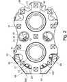
Das Implantat umfasst eine obere Platte
Zwischen der oberen Platte
Die Getriebe bestehen jeweils aus einer Gewindespindel
Die Gewindespindeln
Das untere Implantatteil
An den inneren Mantelflächen
Eine jede Gewindehülse
Die Gewindehülsen
Zum anderen bewirkt die Drehbewegung auf eine jede Gewindehülse
Auf diese Weise erfolgt das Aufspreizen des Implantats bei Drehung einer der beiden Gewindehülsen in einer gleichmäßigen Bewegung, und ein Verkanten der Gewinde wird vermieden.In this way, the spreading of the implant takes place during rotation of one of the two threaded sleeves in a uniform movement, and tilting of the thread is avoided.
Unterhalb des Zahnrads
Tellerrad
Durch eine Drehung des Tellerrads
Parallel zu den Längsachsen (z-Richtung) der Gewindehülsen- und -spindeln
An der Gewindehülse
Untere Platte
Insgesamt sind auf dem Horizontalabschnitt
Die verschiedenen, unterschiedlich orientierten Gewindebohrungen
Jeweils zwei Gewindebohrungen
Um eine gute knöcherne Durchbauung zu gewährleisten, sind die Gewindespindeln
Die Stirnflächen der Gewindehülsen
Die obere Platte
In einer Variante können die obere Platte
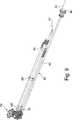
Das Implantat wird mit einem Instrument
Um das Implantat für die spätere Handhabung, d.h. Einbringen, Positionieren, Aufspreizen, sicher an dem Bedieninstrument
Zum Aufspreizen des Implantats umfasst das Instrument
Das Instrument
Das Schraubinstrument
Durch die Verschlussschraube
Durch die Verschraubung des Implantats mit den Schraubgewinden
Die Längsachsen der beiden Aufnahmerohre
Zur besseren Positionierung des proximalen Endes
Die Drehwelle
Durch die geringe Größe des Kegelantriebs
Da der Antrieb des Implantats über das Tellerrad
ZITATE ENTHALTEN IN DER BESCHREIBUNG QUOTES INCLUDE IN THE DESCRIPTION
Diese Liste der vom Anmelder aufgeführten Dokumente wurde automatisiert erzeugt und ist ausschließlich zur besseren Information des Lesers aufgenommen. Die Liste ist nicht Bestandteil der deutschen Patent- bzw. Gebrauchsmusteranmeldung. Das DPMA übernimmt keinerlei Haftung für etwaige Fehler oder Auslassungen.This list of the documents listed by the applicant has been generated automatically and is included solely for the better information of the reader. The list is not part of the German patent or utility model application. The DPMA assumes no liability for any errors or omissions.
Zitierte PatentliteraturCited patent literature
- EP 1415622 A1[0012]EP 1415622 A1[0012]
- US 5236460[0013]US 5236460[0013]
- WO 2009/064787[0014]WO 2009/064787[0014]
Claims (10)
Translated fromGermanPriority Applications (3)
| Application Number | Priority Date | Filing Date | Title |
|---|---|---|---|
| DE201310102451DE102013102451A1 (en) | 2013-03-12 | 2013-03-12 | Spreadable implant for the spine |
| EP14158937.4AEP2777629B1 (en) | 2013-03-12 | 2014-03-11 | Spreadable implant for the spinal column. |
| US14/205,647US9539106B2 (en) | 2013-03-12 | 2014-03-12 | Expandable implant for the spinal column |
Applications Claiming Priority (1)
| Application Number | Priority Date | Filing Date | Title |
|---|---|---|---|
| DE201310102451DE102013102451A1 (en) | 2013-03-12 | 2013-03-12 | Spreadable implant for the spine |
Publications (1)
| Publication Number | Publication Date |
|---|---|
| DE102013102451A1true DE102013102451A1 (en) | 2014-09-18 |
Family
ID=50239519
Family Applications (1)
| Application Number | Title | Priority Date | Filing Date |
|---|---|---|---|
| DE201310102451WithdrawnDE102013102451A1 (en) | 2013-03-12 | 2013-03-12 | Spreadable implant for the spine |
Country Status (3)
| Country | Link |
|---|---|
| US (1) | US9539106B2 (en) |
| EP (1) | EP2777629B1 (en) |
| DE (1) | DE102013102451A1 (en) |
Families Citing this family (43)
| Publication number | Priority date | Publication date | Assignee | Title |
|---|---|---|---|---|
| US7041309B2 (en) | 2002-06-13 | 2006-05-09 | Neuropro Technologies, Inc. | Spinal fusion using an HMG-CoA reductase inhibitor |
| US8597360B2 (en) | 2004-11-03 | 2013-12-03 | Neuropro Technologies, Inc. | Bone fusion device |
| US9526525B2 (en) | 2006-08-22 | 2016-12-27 | Neuropro Technologies, Inc. | Percutaneous system for dynamic spinal stabilization |
| US8088163B1 (en) | 2008-02-06 | 2012-01-03 | Kleiner Jeffrey B | Tools and methods for spinal fusion |
| US20210378834A1 (en) | 2008-05-22 | 2021-12-09 | Spinal Surgical Strategies, Inc., A Nevada Corporation D/B/A Kleiner Device Labs | Spinal fusion cage system with inserter |
| US8366748B2 (en) | 2008-12-05 | 2013-02-05 | Kleiner Jeffrey | Apparatus and method of spinal implant and fusion |
| US9247943B1 (en) | 2009-02-06 | 2016-02-02 | Kleiner Intellectual Property, Llc | Devices and methods for preparing an intervertebral workspace |
| WO2011011626A2 (en)* | 2009-07-22 | 2011-01-27 | Spinex Tec, Llc | Coaxial screw gear sleeve mechanism |
| US9629729B2 (en) | 2009-09-18 | 2017-04-25 | Spinal Surgical Strategies, Llc | Biological delivery system with adaptable fusion cage interface |
| US10973656B2 (en) | 2009-09-18 | 2021-04-13 | Spinal Surgical Strategies, Inc. | Bone graft delivery system and method for using same |
| US10245159B1 (en) | 2009-09-18 | 2019-04-02 | Spinal Surgical Strategies, Llc | Bone graft delivery system and method for using same |
| US8906028B2 (en) | 2009-09-18 | 2014-12-09 | Spinal Surgical Strategies, Llc | Bone graft delivery device and method of using the same |
| US20170238984A1 (en) | 2009-09-18 | 2017-08-24 | Spinal Surgical Strategies, Llc | Bone graft delivery device with positioning handle |
| US8353963B2 (en)* | 2010-01-12 | 2013-01-15 | Globus Medical | Expandable spacer and method for use thereof |
| EP2547292B1 (en) | 2010-03-16 | 2019-04-24 | Pinnacle Spine Group, LLC | Ntervertebral implants and graft delivery systems |
| US9358123B2 (en) | 2011-08-09 | 2016-06-07 | Neuropro Spinal Jaxx, Inc. | Bone fusion device, apparatus and method |
| US10420654B2 (en) | 2011-08-09 | 2019-09-24 | Neuropro Technologies, Inc. | Bone fusion device, system and method |
| WO2013023096A1 (en) | 2011-08-09 | 2013-02-14 | Neuropro Technologies, Inc. | Bone fusion device, system and method |
| US9380932B1 (en) | 2011-11-02 | 2016-07-05 | Pinnacle Spine Group, Llc | Retractor devices for minimally invasive access to the spine |
| US9271777B2 (en) | 2011-12-14 | 2016-03-01 | Biomet Spine, Llc | Unilateral moveable interbody fusion device and method of use |
| US10159583B2 (en) | 2012-04-13 | 2018-12-25 | Neuropro Technologies, Inc. | Bone fusion device |
| US9532883B2 (en) | 2012-04-13 | 2017-01-03 | Neuropro Technologies, Inc. | Bone fusion device |
| EP2838452B1 (en)* | 2012-04-16 | 2019-05-08 | BioSpine, LLC | Multiple spindle adjustable interbody fusion devices |
| EP2948106B1 (en) | 2013-01-24 | 2021-05-26 | BioSpine, LLC | Adjustable interbody fusion device |
| WO2014159739A1 (en) | 2013-03-14 | 2014-10-02 | Pinnacle Spine Group, Llc | Interbody implants and graft delivery systems |
| CA2906531C (en) | 2013-03-15 | 2020-10-06 | Neuropro Technologies, Inc. | Bodiless bone fusion device, apparatus and method |
| US9980825B2 (en) | 2013-05-13 | 2018-05-29 | Biospine, Llc | Adjustable interbody fusion devices |
| DE102013107723A1 (en)* | 2013-07-19 | 2015-01-22 | Heinrich Böhm | Spreadable implant for the spine |
| EP3068347B1 (en)* | 2013-11-11 | 2021-02-17 | 41medical AG | Expandable spinal implant |
| CN104983488B (en)* | 2015-05-19 | 2017-01-04 | 南方医科大学 | A kind of artificial cervical prosthese |
| USD797290S1 (en) | 2015-10-19 | 2017-09-12 | Spinal Surgical Strategies, Llc | Bone graft delivery tool |
| US10219914B2 (en)* | 2015-11-10 | 2019-03-05 | Globus Medical, Inc. | Stabilized expandable intervertebral spacer |
| AU2017228529B2 (en)* | 2016-09-12 | 2022-03-10 | Vb Spine Us Opco Llc | Interbody implant with independent control of expansion at multiple locations |
| AU2017251734B2 (en) | 2016-10-26 | 2022-10-20 | Vb Spine Us Opco Llc | Expandable interbody implant with lateral articulation |
| US10729560B2 (en) | 2017-01-18 | 2020-08-04 | Neuropro Technologies, Inc. | Bone fusion system, device and method including an insertion instrument |
| US10973657B2 (en) | 2017-01-18 | 2021-04-13 | Neuropro Technologies, Inc. | Bone fusion surgical system and method |
| US10111760B2 (en) | 2017-01-18 | 2018-10-30 | Neuropro Technologies, Inc. | Bone fusion system, device and method including a measuring mechanism |
| US10213321B2 (en) | 2017-01-18 | 2019-02-26 | Neuropro Technologies, Inc. | Bone fusion system, device and method including delivery apparatus |
| EP3357459A1 (en) | 2017-02-03 | 2018-08-08 | Spinal Surgical Strategies, LLC | Bone graft delivery device with positioning handle |
| EP4013357B1 (en) | 2019-08-15 | 2025-04-23 | Adcura, Inc. | Dual-axis adjustable spinal systems and interbody fusion devices with fixation |
| WO2021030644A1 (en)* | 2019-08-15 | 2021-02-18 | Spineex, Inc. | Translating dual axis adjustable interbody fusion spinal system |
| EP4312890A1 (en)* | 2021-04-02 | 2024-02-07 | Nuvasive, Inc. | Expansion driver |
| US12370058B2 (en)* | 2022-04-05 | 2025-07-29 | Spine Wave, Inc. | Belt driven expandable interbody fusion device |
Citations (5)
| Publication number | Priority date | Publication date | Assignee | Title |
|---|---|---|---|---|
| US5236460A (en) | 1990-02-12 | 1993-08-17 | Midas Rex Pneumatic Tools, Inc. | Vertebral body prosthesis |
| EP1415622A1 (en) | 2002-10-16 | 2004-05-06 | Advanced Medical Technologies AG | Spreading implant for positioning between two vertebral bodies of the spine |
| WO2009064787A2 (en) | 2007-11-12 | 2009-05-22 | Synthes (U.S.A.) | Adjustable height intervertebral implant |
| US20110160861A1 (en)* | 2009-07-22 | 2011-06-30 | Jimenez Omar F | Methods and apparatuses for vertebral body distraction and fusion employing a coaxial screw gear sleeve mechanism |
| US20120179255A1 (en)* | 2011-01-12 | 2012-07-12 | Ebi, Llc | Expandable spinal implant device |
Family Cites Families (6)
| Publication number | Priority date | Publication date | Assignee | Title |
|---|---|---|---|---|
| US8591587B2 (en)* | 2007-10-30 | 2013-11-26 | Aesculap Implant Systems, Llc | Vertebral body replacement device and method for use to maintain a space between two vertebral bodies within a spine |
| US20100145455A1 (en)* | 2008-12-10 | 2010-06-10 | Innvotec Surgical, Inc. | Lockable spinal implant |
| US8636746B2 (en)* | 2009-12-31 | 2014-01-28 | Spinex Tec, Llc | Methods and apparatus for insertion of vertebral body distraction and fusion devices |
| US8353963B2 (en)* | 2010-01-12 | 2013-01-15 | Globus Medical | Expandable spacer and method for use thereof |
| US8602044B2 (en) | 2010-07-22 | 2013-12-10 | Slingfin, Inc. | Tent assembly |
| EP2838452B1 (en)* | 2012-04-16 | 2019-05-08 | BioSpine, LLC | Multiple spindle adjustable interbody fusion devices |
- 2013
- 2013-03-12DEDE201310102451patent/DE102013102451A1/ennot_activeWithdrawn
- 2014
- 2014-03-11EPEP14158937.4Apatent/EP2777629B1/enactiveActive
- 2014-03-12USUS14/205,647patent/US9539106B2/enactiveActive
Patent Citations (5)
| Publication number | Priority date | Publication date | Assignee | Title |
|---|---|---|---|---|
| US5236460A (en) | 1990-02-12 | 1993-08-17 | Midas Rex Pneumatic Tools, Inc. | Vertebral body prosthesis |
| EP1415622A1 (en) | 2002-10-16 | 2004-05-06 | Advanced Medical Technologies AG | Spreading implant for positioning between two vertebral bodies of the spine |
| WO2009064787A2 (en) | 2007-11-12 | 2009-05-22 | Synthes (U.S.A.) | Adjustable height intervertebral implant |
| US20110160861A1 (en)* | 2009-07-22 | 2011-06-30 | Jimenez Omar F | Methods and apparatuses for vertebral body distraction and fusion employing a coaxial screw gear sleeve mechanism |
| US20120179255A1 (en)* | 2011-01-12 | 2012-07-12 | Ebi, Llc | Expandable spinal implant device |
Also Published As
| Publication number | Publication date |
|---|---|
| US20140288652A1 (en) | 2014-09-25 |
| EP2777629A1 (en) | 2014-09-17 |
| US9539106B2 (en) | 2017-01-10 |
| EP2777629B1 (en) | 2016-07-27 |
Similar Documents
| Publication | Publication Date | Title |
|---|---|---|
| EP2777629B1 (en) | Spreadable implant for the spinal column. | |
| EP2826446B1 (en) | Operating tool for an implant | |
| EP3272315B1 (en) | Instrument for introducing a spinal implant and spinal implant | |
| EP1481654B1 (en) | Intervertebral fusion implant and instrument for placement and distraction of said implant | |
| EP1841385B1 (en) | Implant for transforaminal intracorporeal fusion | |
| DE69733976T2 (en) | Surgical drill and retractor | |
| DE69628352T2 (en) | Zwischenwirbelfusionierungseinrichtung | |
| DE69832542T2 (en) | fusion implant | |
| EP1121075B1 (en) | Telescopic vertebral prosthesis | |
| DE69808438T2 (en) | hip prosthesis | |
| DE60020851T2 (en) | MINIMALLY INVASIVE INSTRUMENTATION FOR A POSTERIOR INTERMEDIATE COLUMN CORRECTION | |
| EP1361840B1 (en) | Distractible vertebral column implant | |
| DE19529605C2 (en) | Intervertebral implant | |
| DE69628286T2 (en) | DEVICE FOR INSERTING SPINAL IMPLANTS | |
| DE102013004964B4 (en) | Instrument set and method for inserting a basket into the disc space between two vertebral bodies | |
| EP1713421B1 (en) | Intervertebral implant for spondylodesis of a lumbar vertebral column | |
| EP1572040A2 (en) | Implant used in procedures for stiffening the vertebral column | |
| DE20023715U1 (en) | Dynamic fusion device for facilitating arthrodesis between vertebrae has legs define engaging member receiving cavity, and engaging member, such as a disc, secured to body and received within cavity | |
| DE9413471U1 (en) | Ventral intervertebral implant | |
| DE29623247U1 (en) | Instruments for the surgical correction of human thoracic and lumbar spine disease in an access from the lateral side of the spine | |
| DE102004043995A1 (en) | Surgical instrument | |
| DE60018988T2 (en) | CURVED CAGE FOR IMMOBILIZING THE SPINE | |
| EP4210603A1 (en) | Medical instrument set, medical device and medical method | |
| EP1491165A1 (en) | Vertebral prosthesis | |
| DE102012203256A1 (en) | Implant structure for supporting spine in inter vertebral space, has anterior support element and posterior support element that are connected with adjusting mechanism where support elements are spaced apart at a distance |
Legal Events
| Date | Code | Title | Description |
|---|---|---|---|
| R012 | Request for examination validly filed | ||
| R016 | Response to examination communication | ||
| R120 | Application withdrawn or ip right abandoned |