DE102013020947A1 - Method for tracking a target object with brightness change, camera system and motor vehicle - Google Patents
Method for tracking a target object with brightness change, camera system and motor vehicleDownload PDFInfo
- Publication number
- DE102013020947A1 DE102013020947A1DE102013020947.1ADE102013020947ADE102013020947A1DE 102013020947 A1DE102013020947 A1DE 102013020947A1DE 102013020947 ADE102013020947 ADE 102013020947ADE 102013020947 A1DE102013020947 A1DE 102013020947A1
- Authority
- DE
- Germany
- Prior art keywords
- brightness
- target object
- motor vehicle
- camera
- change
- Prior art date
- Legal status (The legal status is an assumption and is not a legal conclusion. Google has not performed a legal analysis and makes no representation as to the accuracy of the status listed.)
- Withdrawn
Links
Images


Classifications
- G—PHYSICS
- G06—COMPUTING OR CALCULATING; COUNTING
- G06V—IMAGE OR VIDEO RECOGNITION OR UNDERSTANDING
- G06V20/00—Scenes; Scene-specific elements
- G06V20/50—Context or environment of the image
- G06V20/56—Context or environment of the image exterior to a vehicle by using sensors mounted on the vehicle
- G—PHYSICS
- G06—COMPUTING OR CALCULATING; COUNTING
- G06V—IMAGE OR VIDEO RECOGNITION OR UNDERSTANDING
- G06V10/00—Arrangements for image or video recognition or understanding
- G06V10/10—Image acquisition
- G06V10/12—Details of acquisition arrangements; Constructional details thereof
- G06V10/14—Optical characteristics of the device performing the acquisition or on the illumination arrangements
- G06V10/141—Control of illumination
- G—PHYSICS
- G06—COMPUTING OR CALCULATING; COUNTING
- G06V—IMAGE OR VIDEO RECOGNITION OR UNDERSTANDING
- G06V10/00—Arrangements for image or video recognition or understanding
- G06V10/20—Image preprocessing
- G06V10/255—Detecting or recognising potential candidate objects based on visual cues, e.g. shapes
Landscapes
- Engineering & Computer Science (AREA)
- Physics & Mathematics (AREA)
- General Physics & Mathematics (AREA)
- Multimedia (AREA)
- Theoretical Computer Science (AREA)
- Traffic Control Systems (AREA)
- Image Analysis (AREA)
Abstract
Translated fromGermanDescription
Translated fromGermanDie Erfindung betrifft ein Verfahren zum Verfolgen eines Zielobjekts mittels eines Kamerasystems eines Kraftfahrzeugs, wobei durch eine Kamera des Kamerasystems eine Sequenz von Bildern eines Umgebungsbereichs des Kraftfahrzeugs bereitgestellt wird und das Verfolgen durch eine Bildverarbeitungseinrichtung anhand der Sequenz der Bilder erfolgt. Die Erfindung betrifft außerdem ein Kamerasystem zum Durchführen eines solchen Verfahrens sowie ein Kraftfahrzeug mit einem derartigen Kamerasystem.The invention relates to a method for tracking a target object by means of a camera system of a motor vehicle, wherein a sequence of images of an environmental region of the motor vehicle is provided by a camera of the camera system and the tracking is performed by an image processing device based on the sequence of the images. The invention also relates to a camera system for carrying out such a method and to a motor vehicle having such a camera system.
Vorliegend richtet sich das Interesse insbesondere auf die Verfolgung von Zielfahrzeugen mit Hilfe einer Frontkamera eines Kraftfahrzeugs. Frontkameras für Kraftfahrzeuge sind dabei bereits aus dem Stand der Technik bekannt und erfassen üblicherweise Bilder eines Umgebungsbereichs vor dem Kraftfahrzeug. Diese Sequenz von Bildern wird mittels einer elektronischen Bildverarbeitungseinrichtung verarbeitet, welche in den Bildern Zielobjekte detektiert. Dazu werden die Bilder einem Objektdetektionsalgorithmus unterzogen. Solche Detektionsalgorithmen sind bereits Stand der Technik und basieren beispielsweise auf einer Mustererkennung. Um ein Zielobjekt zu detektieren, können zunächst so genannte charakteristische Punkte aus dem Bild extrahiert und anhand dieser charakteristischen Punkte dann ein Zielobjekt identifiziert werden. Als Beispiel können dabei folgende Algorithmen genannt werden: AdaBoost und HOG-SVM.In the present case, the interest is directed in particular to the tracking of target vehicles with the aid of a front camera of a motor vehicle. Front cameras for motor vehicles are already known from the prior art and usually capture images of a surrounding area in front of the motor vehicle. This sequence of images is processed by means of an electronic image processing device which detects target objects in the images. For this, the images are subjected to an object detection algorithm. Such detection algorithms are already state of the art and are based, for example, on pattern recognition. In order to detect a target object, so-called characteristic points can first be extracted from the image, and then a target object can be identified on the basis of these characteristic points. As an example, the following algorithms can be mentioned: AdaBoost and HOG-SVM.
Wird ein Zielobjekt in einem Bild der Kamera identifiziert, so kann dieses Zielobjekt auch über die nachfolgenden Bilder der Sequenz hinweg verfolgt werden. Das Zielobjekt wird dabei in jedem Bild detektiert, wobei die Detektion in dem aktuellen Bild der Detektion aus dem vorherigen Bild zugeordnet werden muss. Durch das Verfolgen des Zielobjekts sind die aktuelle Position des Zielobjekts in dem Bildrahmen und somit auch die aktuelle relative Position des Zielobjekts bezüglich des Kraftfahrzeugs stets bekannt. Als Verfolgungsalgorithmus kann dabei beispielsweise die Lucas-Kanade-Methode genutzt werden. Ein genanntes Kamerasystem mit einer Frontkamera kann als Kollisionswarnungssystem genutzt werden, mittels welchem der Fahrer vor einer Kollisionsgefahr mit dem Zielobjekt gewarnt werden kann. Ein solches Kollisionswarnungssystem kann beispielsweise Warnsignale ausgeben, um den Fahrer über die detektierte Kollisionsgefahr akustisch und/oder optisch und/oder haptisch zu informieren. Ergänzend oder alternativ kann das Kamerasystem auch als automatisches Bremsassistenzsystem genutzt werden, welches dazu ausgelegt ist, aufgrund der detektierten Kollisionsgefahr automatische Bremseingriffe des Kraftfahrzeugs vorzunehmen. Als Maß für die aktuelle Kollisionsgefahr kann dabei beispielsweise die so genannte Zeit bis zur Kollision (time to collision) genutzt werden, das heißt eine Zeitdauer, welche durch das Kraftfahrzeug voraussichtlich benötigt wird, um das Zielobjekt zu erreichen. Diese Zeit bis zur Kollision kann aus der eingeschätzten Entfernung des Zielobjekts sowie aus der relativen Geschwindigkeit berechnet werden.If a target object is identified in an image of the camera, then this target object can also be tracked over the subsequent images of the sequence. The target object is detected in each image, whereby the detection in the current image must be assigned to the detection from the previous image. By tracking the target object, the current position of the target object in the image frame and thus also the current relative position of the target object with respect to the motor vehicle are always known. For example, the Lucas-Kanade method can be used as the tracking algorithm. A named camera system with a front camera can be used as a collision warning system, by means of which the driver can be warned of a risk of collision with the target object. Such a collision warning system can output warning signals, for example, in order to inform the driver acoustically and / or visually and / or haptically about the detected risk of collision. Additionally or alternatively, the camera system can also be used as an automatic brake assist system, which is designed to make automatic braking interventions of the motor vehicle on the basis of the detected risk of collision. As a measure of the current risk of collision, for example, the so-called time to collision (time to collision) can be used, that is, a period of time, which is expected to be required by the motor vehicle to reach the target object. This time to collision can be calculated from the estimated distance of the target object as well as from the relative velocity.
Als problematisch bei Kamerasystemen haben sich Situationen erwiesen, in denen sich die Beleuchtungsbedingungen im Bereich des Zielobjekts und somit auch die Helligkeit des Zielobjekts selbst abrupt ändern. Solche Änderungen der Beleuchtungsbedingungen treten insbesondere bei einem Tunneleingang bzw. einem Tunnelausgang auf. Tritt ein aktuell verfolgtes Zielfahrzeug in einen Tunnel ein und befindet sich das Kraftfahrzeug mit dem Kamerasystem weiterhin außerhalb des Tunnels, so tritt aus der Sicht des Kamerasystems ein abrupter Einbruch in der Helligkeit des Zielfahrzeugs in den Bildern auf. Dies kann unter Umständen auch dazu führen, dass der Verfolgungsalgorithmus das Zielfahrzeug aus der Sicht verliert und dieses Zielfahrzeug dann nicht mehr durch das Kamerasystem verfolgt werden kann.Situations in which the lighting conditions in the region of the target object and thus also the brightness of the target object themselves abruptly change have proven problematic with camera systems. Such changes in the illumination conditions occur in particular at a tunnel entrance or a tunnel exit. If a currently tracked target vehicle enters a tunnel and if the motor vehicle with the camera system continues to be outside the tunnel, an abrupt decline in the brightness of the target vehicle occurs in the images from the point of view of the camera system. Under some circumstances, this can also lead to the tracking algorithm losing sight of the target vehicle and then being unable to follow this target vehicle by the camera system.
Es ist Aufgabe der Erfindung, eine Lösung aufzuzeigen, wie bei einem Verfahren der eingangs genannten Gattung das Zielobjekt besonders zuverlässig auch bei abrupten Änderungen von Beleuchtungsbedingungen im Bereich des Zielobjekts verfolgt werden kann.It is an object of the invention to provide a solution, as in a method of the type mentioned, the target can be tracked particularly reliable even in abrupt changes of lighting conditions in the region of the target object.
Diese Aufgabe wird erfindungsgemäß durch ein Verfahren, durch ein Kamerasystem sowie durch ein Kraftfahrzeug mit den Merkmalen gemäß den jeweiligen unabhängigen Patentansprüchen gelöst. Vorteilhafte Ausführungen der Erfindung sind Gegenstand der abhängigen Patentansprüche, der Beschreibung und der Figuren.This object is achieved by a method by a camera system and by a motor vehicle with the features according to the respective independent claims. Advantageous embodiments of the invention are the subject of the dependent claims, the description and the figures.
Ein erfindungsgemäßes Verfahren dient zum Verfolgen eines Zielobjekts mittels eines Kamerasystems eines Kraftfahrzeugs, wobei durch eine Kamera des Kamerasystems eine Sequenz von Bildern eines Umgebungsbereichs des Kraftfahrzeugs bereitgestellt wird und das Verfolgen des Zielobjekts durch eine Bildverarbeitungseinrichtung anhand der Sequenz der Bilder erfolgt. Das Zielobjekt wird in einem Bild der Sequenz detektiert und über nachfolgende Bilder der Sequenz hinweg unter Verwendung eines vorgegebenen Verfolgungsalgorithmus durch die Bildverarbeitungseinrichtung verfolgt. Es kann dabei ein beliebiger Verfolgungsalgorithmus verwendet werden, so dass vorliegend auf den Verfolgungsalgorithmus nicht mehr eingegangen wird. Es werden Helligkeitswerte von Bildpunkten des Zielobjekts in den jeweiligen Bildern erfasst. Die Bildverarbeitungseinrichtung detektiert dann eine Änderung einer Helligkeit des abgebildeten Zielobjekts anhand der Helligkeitswerte. Falls diese Änderung der Helligkeit ein vorbestimmtes Ausmaß überschreitet, wird zumindest ein Parameter des Verfolgungsalgorithmus und/oder zumindest ein Parameter der Kamera aufgrund der Detektion der Änderung beeinflusst.A method according to the invention serves to track a target object by means of a camera system of a motor vehicle, wherein a sequence of images of a surrounding area of the motor vehicle is provided by a camera of the camera system and the tracking of the target object by an image processing device is based on the sequence of the images. The target object is detected in an image of the sequence and tracked through subsequent images of the sequence using a predetermined tracking algorithm by the image processing device. An arbitrary tracking algorithm can be used, so that in the present case the tracking algorithm is no longer discussed. Brightness values of pixels of the target object in the respective images are detected. The image processing device then detects a change in brightness of the imaged target object on the basis of Brightness values. If this change in brightness exceeds a predetermined extent, at least one parameter of the tracking algorithm and / or at least one parameter of the camera is affected due to the detection of the change.
Demnach erfasst die Bildverarbeitungseinrichtung die Helligkeitswerte von Bildpunkten des Zielobjekts in den jeweiligen Bildern und kann eine Änderung in der Helligkeit des abgebildeten Zielobjekts anhand der erfassten Helligkeitswerte detektieren. Überschreitet diese Änderung der Helligkeit des Zielobjekts ein vorbestimmtes Ausmaß (beispielsweise 30% oder 40% oder 50% oder 60% oder 70% oder 80% oder 90% innerhalb einer vorgegebenen Anzahl von Einzelbildern (Frames) bzw. innerhalb einer vorgegebenen Zeitdauer), so beeinflusst die Bildverarbeitungseinrichtung zumindest einen Parameter des Verfolgungsalgorithmus und/oder zumindest einen Parameter der Kamera. Solche Änderungen der Helligkeit des abgebildeten Zielobjekts treten beispielsweise bei Eintritt des Zielobjekts in einen Tunnel auf, während sich das Kraftfahrzeug weiterhin außerhalb des Tunnels befindet. Es kann jedoch auch der umgekehrte Fall eintreten: Befinden sich sowohl das Zielfahrzeug als auch das Ego-Kraftfahrzeug in einem Tunnel und erreicht das Zielfahrzeug den Tunnelausgang, so verändert sich die Helligkeit des Zielobjekts in den Bildern abrupt, wobei hier das Zielfahrzeug deutlich heller als die Umgebung der Kamera wird. In beiden Fällen erweist sich das erfindungsgemäße Verfahren als besonders vorteilhaft, denn die Bildverarbeitungseinrichtung kann beispielsweise das so genannte Keep-Alive-Zeitintervall des Verfolgungsalgorithmus so beeinflussen, dass das detektierte Zielobjekt auch bei Fehlen von Detektionen in den aktuellen Bildern weiterhin als präsent interpretiert wird. Ergänzend oder alternativ kann die Bildverarbeitungseinrichtung Steuersignale an die Kamera abgeben, um beispielsweise die Integrationszeit des Bildsensors derart zu beeinflussen, dass diese Integrationszeit an die Helligkeit des Zielobjekts angepasst wird und das Zielobjekt somit weiterhin in den Bildern detektiert werden kann. Das erfindungsgemäße Verfahren hat somit insgesamt den Vorteil, dass das Zielobjekt auch bei abrupten Änderungen der Beleuchtungsbedingungen, wie beispielsweise bei einem Tunneleingang, besonders zuverlässig durch die Bildverarbeitungseinrichtung verfolgt werden kann.Accordingly, the image processing device acquires the brightness values of pixels of the target object in the respective images, and can detect a change in the brightness of the imaged target object based on the detected brightness values. If this change in brightness of the target exceeds a predetermined amount (for example, 30% or 40% or 50% or 60% or 70% or 80% or 90% within a predetermined number of frames, or within a predetermined period of time), then the image processing device influences at least one parameter of the tracking algorithm and / or at least one parameter of the camera. Such changes in the brightness of the imaged target object occur, for example, when the target object enters a tunnel while the motor vehicle continues to be outside the tunnel. However, the reverse case can also occur: If both the target vehicle and the ego motor vehicle are in a tunnel and the target vehicle reaches the tunnel exit, the brightness of the target object changes abruptly in the images, in which case the target vehicle is significantly brighter than the target vehicle Surrounding the camera. In both cases, the inventive method proves to be particularly advantageous because the image processing device, for example, the so-called keep-alive time interval of the tracking algorithm influence so that the detected target object continues to be interpreted as present even in the absence of detections in the current images. Additionally or alternatively, the image processing device can deliver control signals to the camera in order, for example, to influence the integration time of the image sensor such that this integration time is adapted to the brightness of the target object and the target object can thus continue to be detected in the images. The method according to the invention thus has the overall advantage that the target object can be tracked particularly reliably by the image processing device even in the event of abrupt changes in the illumination conditions, for example in the case of a tunnel entrance.
Die Kamera ist vorzugsweise eine Frontkamera, welche insbesondere hinter einer Windschutzscheibe des Kraftfahrzeugs angeordnet ist, beispielsweise direkt an der Windschutzscheibe im Innenraum des Kraftfahrzeugs. Die Frontkamera erfasst dann die Umgebung in Fahrtrichtung bzw. in Fahrzeuglängsrichtung vor dem Kraftfahrzeug. Dies kann insbesondere bedeuten, dass eine senkrecht zur Ebene des Bildsensors verlaufende Kameraachse parallel und somit entlang der Fahrzeuglängsachse orientiert ist.The camera is preferably a front camera, which is arranged in particular behind a windshield of the motor vehicle, for example, directly on the windshield in the interior of the motor vehicle. The front camera then detects the environment in the direction of travel or in the vehicle longitudinal direction in front of the motor vehicle. This may in particular mean that a camera axis running perpendicular to the plane of the image sensor is oriented parallel and thus along the vehicle longitudinal axis.
Die Kamera ist vorzugsweise eine Videokamera, welche eine Vielzahl von Bildern (Frames) pro Sekunde bereitstellen kann. Die Kamera kann eine CCD-Kamera oder eine CMOS-Kamera sein.The camera is preferably a video camera which can provide a plurality of frames per second. The camera can be a CCD camera or a CMOS camera.
Das Kamerasystem kann ein Kollisionswarnungssystem sein, mittels welchem ein Gefahrengrad bezüglich einer Kollision des Kraftfahrzeugs mit dem Zielobjekt bestimmt und abhängig von dem aktuellen Gefahrengrad ein Warnsignal ausgegeben wird, mit welchem die Kollisionsgefahr dem Fahrer signalisiert wird. Ergänzend oder alternativ kann das Kamerasystem auch als automatisches Bremsassistenzsystem ausgebildet sein, mittels welchem Bremseingriffe automatisch in Abhängigkeit von dem Gefahrengrad durchgeführt werden. Als Gefahrengrad kann dabei beispielsweise die Zeit bis zur Kollision und/oder eine Entfernung des Zielobjekts von dem Kraftfahrzeug verwendet werden.The camera system may be a collision warning system, by means of which a degree of danger with respect to a collision of the motor vehicle with the target object is determined and depending on the current degree of danger a warning signal is output, with which the risk of collision is signaled to the driver. Additionally or alternatively, the camera system can also be designed as an automatic brake assist system, by means of which braking interventions are automatically performed as a function of the degree of danger. As a degree of danger, the time to collision and / or removal of the target object from the motor vehicle can be used, for example.
Wie bereits ausgeführt, kann als Parameter der Kamera beispielsweise eine Integrationszeit des Bildsensors beeinflusst werden, falls eine Änderung der Helligkeit des abgebildeten Zielobjekts detektiert wird. Bei einem abrupten Einbruch der Helligkeit des Zielobjekts kann die Integrationszeit des Bildsensors beispielsweise erhöht werden, um zu gewährleisten, dass das Zielobjekt auch nach der Helligkeitsänderung weiterhin detektiert werden kann. Dies hat den Vorteil, dass das Zielobjekt somit weiter verfolgt werden kann und somit gegebenenfalls eine Kollision mit dem Zielobjekt verhindert werden kann.As already explained, an integration time of the image sensor, for example, can be influenced as a parameter of the camera if a change in the brightness of the imaged target object is detected. In the event of an abrupt drop in the brightness of the target object, the integration time of the image sensor can be increased, for example, in order to ensure that the target object can continue to be detected even after the brightness change. This has the advantage that the target object can thus be further tracked and thus, if necessary, a collision with the target object can be prevented.
In einer Ausführungsform ist vorgesehen, dass als Parameter des Verfolgungsalgorithmus ein Keep-Alive-Zeitintervall beeinflusst wird, für welches das detektierte Zielobjekt durch die Bildverarbeitungseinrichtung bei Fehlen von Detektionen in den aktuellen Bildern weiterhin als präsent interpretiert wird. Das Keep-Alive-Zeitintervall definiert also eine Zeitdauer, für welche das detektierte Zielobjekt auch dann als präsent interpretiert wird, wenn dieses Objekt in den aktuellen Bildern nicht detektiert werden kann. Nach der Detektion der Helligkeitsänderung des Zielobjekts kann dieses Keep-Alive-Zeitintervall erhöht werden, um zu gewährleisten, dass die Daten bezüglich dieses Zielobjekts zumindest so lange in einem Speicher der Bildverarbeitungseinrichtung verbleiben, bis das Kraftfahrzeug selbst den Tunneleingang, Tunnelausgang oder dergleichen erreicht. Auch dies erhöht die Sicherheit, da gegebenenfalls eine Kollision mit dem Zielobjekt verhindert werden kann.In one embodiment, it is provided that a keep-alive time interval is influenced as a parameter of the tracking algorithm, for which the detected target object is further interpreted as present by the image processing device in the absence of detections in the current images. The keep-alive time interval thus defines a time period for which the detected target object is interpreted as present even if this object can not be detected in the current images. After detection of the brightness change of the target object, this keep-alive time interval may be increased to ensure that the data relating to this target object remains in a memory of the image processing device at least until the motor vehicle itself reaches the tunnel entrance, tunnel exit or the like. This also increases security, since a collision with the target object can possibly be prevented.
Das Beeinflussen des zumindest einen Parameters kann insbesondere bedeuten, dass der zumindest eine Parameter von einem aktuellen Standardwert auf einen Sonderwert erhöht oder reduziert wird. Soll die Beeinflussung des Parameters nicht mehr erfolgen, so wird der Parameter wieder auf den Standardwert eingestellt.The influencing of the at least one parameter may in particular mean that the at least one parameter of a current Default value is increased or decreased to a special value. If the parameter is no longer influenced, the parameter is reset to the default value.
Hinsichtlich der Detektion der Änderung der Helligkeit des abgebildeten Zielobjekts kann vorgesehen sein, dass zu jedem Bild jeweils ein Mittelwert der Helligkeitswerte der Bildpunkte des Zielobjekts bestimmt wird. Die Änderung der Helligkeit kann dann abhängig von dem zeitlichen Verlauf der Mittelwerte detektiert werden. Die Auswertung der Helligkeitsmittelwerte ermöglicht eine sehr präzise und zuverlässige Detektion von Helligkeitsänderungen des Zielobjekts aufgrund unterschiedlicher Beleuchtungsbedingungen.With regard to the detection of the change in the brightness of the imaged target object, provision may be made for an average of the brightness values of the pixels of the target object to be determined in each case. The change in brightness can then be detected as a function of the time profile of the mean values. The evaluation of the brightness average values enables a very precise and reliable detection of brightness changes of the target object due to different illumination conditions.
Um die Genauigkeit bei der Detektion der Helligkeitsänderung weiterhin zu erhöhen, kann zu jedem Bild auch jeweils ein Verhältnis des jeweiligen Mittelwerts zu der aktuellen Integrationszeit des Bildsensors bestimmt werden. Die Änderung der Helligkeit des abgebildeten Zielobjekts kann dann anhand der Verhältnisse detektiert werden. Es wird somit nicht die absolute Helligkeit des abgebildeten Zielobjekts ausgewertet, sondern eine relative Helligkeit bezüglich der aktuellen Integrationszeit. Somit kann die Detektion der Helligkeitsänderung noch präziser und zuverlässiger erfolgen, da Änderungen der Helligkeit aufgrund einer Änderung der Integrationszeit herausgefiltert werden können.In order to further increase the accuracy in the detection of the change in brightness, a ratio of the respective mean value to the current integration time of the image sensor can also be determined for each image. The change in the brightness of the imaged target object can then be detected based on the conditions. It is thus not the absolute brightness of the imaged target object evaluated, but a relative brightness with respect to the current integration time. Thus, the detection of the brightness change can be made even more precise and reliable, since changes in brightness due to a change in the integration time can be filtered out.
In einer Ausführungsform ist vorgesehen, dass anhand der Änderung der Helligkeit des abgebildeten Zielobjekts ein Tunneleingang oder ein Tunnelausgang vor dem Kraftfahrzeug detektiert wird, nämlich je nachdem, ob die Helligkeit des Zielobjekts abrupt reduziert oder erhöht wird. Die Änderung der Helligkeit wird also durch die Bildverarbeitungseinrichtung als Tunneleingang/Tunnelausgang interpretiert, der sich in Fahrtrichtung vor dem Kraftfahrzeug befindet. Die Information über die Detektion des Tunneleingangs/Tunnelausgangs kann somit auch anderen Systemen zur Verfügung gestellt werden. Die Detektion des Tunneleingangs/Tunnelausgangs hat außerdem den Vorteil, dass in der Bildverarbeitungseinrichtung somit bekannt ist, wann das Kraftfahrzeug und somit die Kamera voraussichtlich in den Tunnel (bzw. aus dem Tunnel) gelangen wird und sich die Helligkeit der Umgebung der Kamera verändern wird. Diese Informationen können dann auch bei der Einstellung des zumindest einen Parameters berücksichtigt werden.In one embodiment, it is provided that based on the change in the brightness of the imaged target object, a tunnel entrance or a tunnel exit in front of the motor vehicle is detected, namely depending on whether the brightness of the target object is abruptly reduced or increased. The change in brightness is thus interpreted by the image processing device as a tunnel entrance / tunnel exit, which is in the direction of travel in front of the motor vehicle. The information about the detection of the tunnel input / tunnel output can thus also be made available to other systems. The detection of the tunnel input / tunnel output also has the advantage that in the image processing device is thus known when the motor vehicle and thus the camera is expected to enter the tunnel (or from the tunnel) and the brightness of the environment of the camera will change. This information can then also be taken into account when setting the at least one parameter.
Also kann in einer Ausführungsform vorgesehen sein, dass eine aktuelle Entfernung des Zielobjekts von dem Kraftfahrzeug bestimmt wird und eine bei der Detektion der Änderung der Helligkeit erfasste Entfernung durch die Bildverarbeitungseinrichtung als eine aktuelle Entfernung des Kraftfahrzeugs von einem Helligkeitsänderungsbereich interpretiert wird (beispielsweise Tunneleingang oder Tunnelausgang), in welchem die Änderung der Helligkeit auch für die Kamera selbst voraussichtlich eintreten wird. Das Beeinflussen des zumindest einen Parameters kann dann in Abhängigkeit von dieser Entfernung des Kraftfahrzeugs von dem Helligkeitsänderungsbereich erfolgen. Beispielsweise wird die aktuelle Entfernung des Kraftfahrzeugs von einem Tunneleingang oder einem Tunnelausgang erfasst und bei der Beeinflussung des zumindest einen Parameters berücksichtigt. Aus der Entfernung zu dem genannten Helligkeitsänderungsbereich sowie aus der aktuellen Geschwindigkeit des Kraftfahrzeugs kann auch die Zeitdauer bis zum Erreichen des Helligkeitsänderungsbereichs berechnet werden. In der Bildverarbeitungseinrichtung ist somit stets bekannt, wann genau das Kraftfahrzeug in den Helligkeitsänderungsbereich (beispielsweise Tunnel) eintreten wird. Der zumindest eine Parameter kann somit situationsabhängig und bedarfsgerecht beeinflusst werden.Thus, in one embodiment, it may be provided that a current distance of the target object from the motor vehicle is determined and a distance detected during the detection of the change in brightness is interpreted by the image processing device as a current distance of the motor vehicle from a brightness change range (for example, tunnel entrance or tunnel exit). in which the change in brightness is also likely to occur for the camera itself. The influencing of the at least one parameter can then take place as a function of this distance of the motor vehicle from the brightness change range. For example, the current distance of the motor vehicle is detected by a tunnel entrance or a tunnel exit and taken into account in the influencing of the at least one parameter. From the distance to the mentioned brightness change range as well as from the current speed of the motor vehicle, the time duration until reaching the brightness change range can also be calculated. In the image processing device is thus always known when exactly the motor vehicle in the brightness change range (for example, tunnel) will occur. The at least one parameter can thus be influenced depending on the situation and needs.
In einer Ausführungsform kann also vorgesehen sein, dass der zumindest eine Parameter der Kamera und/oder der zumindest eine Parameter des Verfolgungsalgorithmus, insbesondere das Keep-Alive-Zeitintervall, nur für die Zeitdauer bis zum Erreichen des Helligkeitsänderungsbereiches beeinflusst wird. Erreicht das Kraftfahrzeug den Helligkeitsänderungsbereich, kann der zumindest eine Parameter wieder auf den Normalwert bzw. Standardwert eingestellt werden. So kann beispielsweise das Keep-Alive-Zeitintervall nur für die Zeitdauer erhöht werden, während welcher sich das Zielobjekt im Tunnel und das Kraftfahrzeug außerhalb des Tunnels befinden. Tritt dann auch das Kraftfahrzeug in den Tunnel ein, kann das Keep-Alive-Zeitintervall wieder auf einen Standardwert reduziert werden, da die Beleuchtungsverhältnisse gleich für das Zielobjekt und das Kraftfahrzeug sind.In one embodiment, it may thus be provided that the at least one parameter of the camera and / or the at least one parameter of the tracking algorithm, in particular the keep-alive time interval, is only influenced for the time until the brightness change range is reached. If the motor vehicle reaches the brightness change range, the at least one parameter can be set to the normal value or standard value again. For example, the keep-alive time interval may only be increased for the period during which the target object is in the tunnel and the motor vehicle is outside the tunnel. If the motor vehicle also enters the tunnel, the keep-alive time interval can be reduced again to a standard value since the lighting conditions are the same for the target object and the motor vehicle.
Die Erfindung betrifft außerdem ein Kamerasystem für ein Kraftfahrzeug, umfassend eine Kamera zum Bereitstellen einer Sequenz von Bildern eines Umgebungsbereichs des Kraftfahrzeugs, sowie umfassend eine Bildverarbeitungseinrichtung zum Verfolgen eines Zielobjekts anhand der Sequenz der Bilder, wobei die Bildverarbeitungseinrichtung zum Durchführen eines erfindungsgemäßen Verfahrens ausgebildet ist.The invention also relates to a camera system for a motor vehicle, comprising a camera for providing a sequence of images of a surrounding area of the motor vehicle, and comprising an image processing device for tracking a target object on the basis of the sequence of images, wherein the image processing device is designed to carry out a method according to the invention.
Ein erfindungsgemäßes Kraftfahrzeug, insbesondere ein Personenkraftwagen, umfasst ein erfindungsgemäßes Kamerasystem.A motor vehicle according to the invention, in particular a passenger car, comprises a camera system according to the invention.
Die mit Bezug auf das erfindungsgemäße Verfahren vorgestellten bevorzugten Ausführungsformen und deren Vorteile gelten entsprechend für das erfindungsgemäße Kamerasystem sowie für das erfindungsgemäße Kraftfahrzeug.The preferred embodiments presented with reference to the method according to the invention and their advantages apply correspondingly to the camera system according to the invention and to the motor vehicle according to the invention.
Weitere Merkmale der Erfindung ergeben sich aus den Ansprüchen, den Figuren und der Figurenbeschreibung. Die vorstehend in der Beschreibung genannten Merkmale und Merkmalskombinationen sowie die nachfolgend in der Figurenbeschreibung genannten und/oder in den Figuren alleine gezeigten Merkmale und Merkmalskombinationen sind nicht nur in der jeweils angegebenen Kombination, sondern auch in anderen Kombinationen oder aber in Alleinstellung verwendbar. Further features of the invention will become apparent from the claims, the figures and the description of the figures. The features and combinations of features mentioned above in the description as well as the features and feature combinations mentioned below in the description of the figures and / or shown alone in the figures can be used not only in the respectively indicated combination but also in other combinations or alone.
Die Erfindung wird nachfolgend anhand eines bevorzugten Ausführungsbeispiels sowie unter Bezugnahme auf die beigefügten Zeichnungen näher erläutert.The invention will be explained in more detail below with reference to a preferred embodiment and with reference to the accompanying drawings.
Es zeigen:Show it:
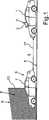
Ein in
Das Kamerasystem
Wie aus
Das Verfolgen des Zielobjekts
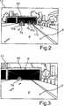
Ein beispielhaftes Bild
In
Um eine solche Situation zu detektieren, erfasst die Bildverarbeitungseinrichtung fortlaufend die Helligkeitswerte der Zielobjekte
Mit erneutem Bezug auf
Mit Bezug auf
Wird durch die Bildverarbeitungseinrichtung zum Zeitpunkt T1 die Änderung
Beispielsweise kann diesbezüglich ein so genanntes Keep-Alive-Zeitintervall erhöht werden, das heißt eine zeitliche Schwelle, bis zu welcher das detektierte Zielfahrzeug
Ergänzend oder alternativ kann zum Zeitpunkt T1 auch die Integrationszeit des Bildsensors selbst derart beeinflusst werden, dass die Helligkeit der Bilder
Werden mehrere Zielfahrzeuge
Claims (11)
Translated fromGermanPriority Applications (3)
| Application Number | Priority Date | Filing Date | Title |
|---|---|---|---|
| DE102013020947.1ADE102013020947A1 (en) | 2013-12-12 | 2013-12-12 | Method for tracking a target object with brightness change, camera system and motor vehicle |
| PCT/EP2014/072153WO2015086200A1 (en) | 2013-12-12 | 2014-10-15 | Method for tracking a target object upon brightness change, camera system and motor vehicle |
| EP14786649.5AEP3080750B1 (en) | 2013-12-12 | 2014-10-15 | Method for tracking a target object upon brightness change, camera system and motor vehicle |
Applications Claiming Priority (1)
| Application Number | Priority Date | Filing Date | Title |
|---|---|---|---|
| DE102013020947.1ADE102013020947A1 (en) | 2013-12-12 | 2013-12-12 | Method for tracking a target object with brightness change, camera system and motor vehicle |
Publications (1)
| Publication Number | Publication Date |
|---|---|
| DE102013020947A1true DE102013020947A1 (en) | 2015-06-18 |
Family
ID=51753205
Family Applications (1)
| Application Number | Title | Priority Date | Filing Date |
|---|---|---|---|
| DE102013020947.1AWithdrawnDE102013020947A1 (en) | 2013-12-12 | 2013-12-12 | Method for tracking a target object with brightness change, camera system and motor vehicle |
Country Status (3)
| Country | Link |
|---|---|
| EP (1) | EP3080750B1 (en) |
| DE (1) | DE102013020947A1 (en) |
| WO (1) | WO2015086200A1 (en) |
Cited By (2)
| Publication number | Priority date | Publication date | Assignee | Title |
|---|---|---|---|---|
| EP3291134A1 (en)* | 2016-09-01 | 2018-03-07 | Samsung Electronics Co., Ltd | Method and apparatus for controlling vision sensor for autonomous vehicle |
| DE102018214938A1 (en)* | 2018-09-03 | 2020-03-05 | Conti Temic Microelectronic Gmbh | The present invention relates to a method for increasing the traffic safety of a ego vehicle and an ego vehicle with a driver assistance system |
Families Citing this family (4)
| Publication number | Priority date | Publication date | Assignee | Title |
|---|---|---|---|---|
| CN109829935B (en)* | 2018-12-29 | 2021-02-19 | 百度在线网络技术(北京)有限公司 | Scene sequence tracking processing method and device of vehicle and vehicle |
| CN112954192B (en)* | 2021-01-27 | 2022-06-07 | 惠州华阳通用电子有限公司 | Camera shooting mode control method |
| CN113642442B (en)* | 2021-08-06 | 2022-11-25 | 展讯通信(上海)有限公司 | Face detection method and device, computer readable storage medium and terminal |
| CN114999179B (en)* | 2022-07-20 | 2022-10-25 | 山东金宇信息科技集团有限公司 | Tunnel safe driving method, equipment and medium |
Citations (2)
| Publication number | Priority date | Publication date | Assignee | Title |
|---|---|---|---|---|
| US20030194110A1 (en)* | 2002-04-16 | 2003-10-16 | Koninklijke Philips Electronics N.V. | Discriminating between changes in lighting and movement of objects in a series of images using different methods depending on optically detectable surface characteristics |
| DE102005008131A1 (en)* | 2005-01-31 | 2006-08-03 | Daimlerchrysler Ag | Object e.g. road sign, detecting method for use with e.g. driver assistance system, involves determining position and movement of relevant pixels using filter and combining relevant pixels to objects under given terms and conditions |
Family Cites Families (3)
| Publication number | Priority date | Publication date | Assignee | Title |
|---|---|---|---|---|
| US6323776B1 (en)* | 1999-12-21 | 2001-11-27 | Snap-On Technologies, Inc. | Method and apparatus of automatically identifying faults in a machine vision measuring system |
| WO2012155956A1 (en)* | 2011-05-16 | 2012-11-22 | Valeo Schalter Und Sensoren Gmbh | Vehicle and method for operating a camera arrangement for a vehicle |
| KR20130126144A (en)* | 2012-05-11 | 2013-11-20 | 주식회사 만도 | Method and apparatus for vehicle detection |
- 2013
- 2013-12-12DEDE102013020947.1Apatent/DE102013020947A1/ennot_activeWithdrawn
- 2014
- 2014-10-15WOPCT/EP2014/072153patent/WO2015086200A1/enactiveApplication Filing
- 2014-10-15EPEP14786649.5Apatent/EP3080750B1/enactiveActive
Patent Citations (2)
| Publication number | Priority date | Publication date | Assignee | Title |
|---|---|---|---|---|
| US20030194110A1 (en)* | 2002-04-16 | 2003-10-16 | Koninklijke Philips Electronics N.V. | Discriminating between changes in lighting and movement of objects in a series of images using different methods depending on optically detectable surface characteristics |
| DE102005008131A1 (en)* | 2005-01-31 | 2006-08-03 | Daimlerchrysler Ag | Object e.g. road sign, detecting method for use with e.g. driver assistance system, involves determining position and movement of relevant pixels using filter and combining relevant pixels to objects under given terms and conditions |
Non-Patent Citations (1)
| Title |
|---|
| Kalal, Z.; Matas, J.; Mikolajczyk, K., "Online learning of robust object detectors during unstable tracking," Computer Vision Workshops (ICCV Workshops), 2009 IEEE 12th International Conference on , vol., no., pp.1417,1424, Sept. 27 2009-Oct. 4 2009;doi: 10.1109/ICCVW.2009.5457446* |
Cited By (3)
| Publication number | Priority date | Publication date | Assignee | Title |
|---|---|---|---|---|
| EP3291134A1 (en)* | 2016-09-01 | 2018-03-07 | Samsung Electronics Co., Ltd | Method and apparatus for controlling vision sensor for autonomous vehicle |
| US10657387B2 (en) | 2016-09-01 | 2020-05-19 | Samsung Electronics Co., Ltd. | Method and apparatus for controlling vision sensor for autonomous vehicle |
| DE102018214938A1 (en)* | 2018-09-03 | 2020-03-05 | Conti Temic Microelectronic Gmbh | The present invention relates to a method for increasing the traffic safety of a ego vehicle and an ego vehicle with a driver assistance system |
Also Published As
| Publication number | Publication date |
|---|---|
| EP3080750B1 (en) | 2024-11-06 |
| EP3080750A1 (en) | 2016-10-19 |
| WO2015086200A1 (en) | 2015-06-18 |
Similar Documents
| Publication | Publication Date | Title |
|---|---|---|
| DE102016216883B4 (en) | Driving assistance device and driving assistance method | |
| EP3187383B1 (en) | Method and device for remotely actuating an actuator of a vehicle | |
| DE102008025723B4 (en) | Device for monitoring the environment of a vehicle | |
| EP2285632B1 (en) | Driver assistance system | |
| DE102009004626B4 (en) | Device for monitoring the environment of a vehicle | |
| DE102013020947A1 (en) | Method for tracking a target object with brightness change, camera system and motor vehicle | |
| DE102016222502A1 (en) | Lane departure warning apparatus and method | |
| WO2014040855A1 (en) | Method for operating a driver assistance system of a vehicle | |
| DE102015224192A1 (en) | Recognition of an open space | |
| EP2949531A2 (en) | Method and driver assistance system for determining dynamic driving states in a commercial vehicle | |
| DE102007039377A1 (en) | Method for automatic longitudinal guidance of a motor vehicle by means of a longitudinal driver assistance system with Stop & Go function | |
| DE102006060893A1 (en) | Device and method for determining a free space in front of a vehicle | |
| DE102013022076A1 (en) | Method for determining a width of a target vehicle by means of a camera system of a motor vehicle, camera system and motor vehicle | |
| WO2005081200A2 (en) | Detection device for a motor vehicle | |
| EP3655299B1 (en) | Method and device for determining an optical flow on the basis of an image sequence captured by a camera of a vehicle | |
| EP3151543B1 (en) | Image pickup device for vehicle and method of driving such an image pick up device | |
| WO2015090691A1 (en) | Method for generating a model of the surroundings of a motor vehicle, driver assistance system and motor vehicle | |
| DE102018201531A1 (en) | Method for detecting a driving tube in rail-bound vehicles | |
| WO2020052840A1 (en) | Method and device for operating an at least semi-automatically operated first vehicle | |
| EP3677019B1 (en) | Method and device for predictable exposure control of at least one first vehicle camera | |
| DE102013022050A1 (en) | Method for tracking a target vehicle, in particular a motorcycle, by means of a motor vehicle, camera system and motor vehicle | |
| DE102012024879A1 (en) | Driver assistance system for at least partially decelerating a motor vehicle, motor vehicle and corresponding method | |
| EP3520020B1 (en) | Road sign classification in a surrounding area of a motor vehicle | |
| DE102016220228A1 (en) | A method, driver assistance system, and vehicle comprising the driver assistance system for adjusting a vehicle distance between an ego vehicle and a first, preceding vehicle in response to a second, preceding vehicle | |
| DE102017008116B4 (en) | Method and device for conclusive detection of traffic violations of a vehicle |
Legal Events
| Date | Code | Title | Description |
|---|---|---|---|
| R163 | Identified publications notified | ||
| R005 | Application deemed withdrawn due to failure to request examination |