DE102013015139A1 - Tool for applying a torque and torque control therefor - Google Patents
Tool for applying a torque and torque control thereforDownload PDFInfo
- Publication number
- DE102013015139A1 DE102013015139A1DE201310015139DE102013015139ADE102013015139A1DE 102013015139 A1DE102013015139 A1DE 102013015139A1DE 201310015139DE201310015139DE 201310015139DE 102013015139 ADE102013015139 ADE 102013015139ADE 102013015139 A1DE102013015139 A1DE 102013015139A1
- Authority
- DE
- Germany
- Prior art keywords
- torque
- tool
- speed
- controller
- control
- Prior art date
- Legal status (The legal status is an assumption and is not a legal conclusion. Google has not performed a legal analysis and makes no representation as to the accuracy of the status listed.)
- Pending
Links
Images
Classifications
- G—PHYSICS
- G05—CONTROLLING; REGULATING
- G05D—SYSTEMS FOR CONTROLLING OR REGULATING NON-ELECTRIC VARIABLES
- G05D17/00—Control of torque; Control of mechanical power
- G05D17/02—Control of torque; Control of mechanical power characterised by the use of electric means
- B—PERFORMING OPERATIONS; TRANSPORTING
- B25—HAND TOOLS; PORTABLE POWER-DRIVEN TOOLS; MANIPULATORS
- B25B—TOOLS OR BENCH DEVICES NOT OTHERWISE PROVIDED FOR, FOR FASTENING, CONNECTING, DISENGAGING OR HOLDING
- B25B23/00—Details of, or accessories for, spanners, wrenches, screwdrivers
- B25B23/14—Arrangement of torque limiters or torque indicators in wrenches or screwdrivers
- Y—GENERAL TAGGING OF NEW TECHNOLOGICAL DEVELOPMENTS; GENERAL TAGGING OF CROSS-SECTIONAL TECHNOLOGIES SPANNING OVER SEVERAL SECTIONS OF THE IPC; TECHNICAL SUBJECTS COVERED BY FORMER USPC CROSS-REFERENCE ART COLLECTIONS [XRACs] AND DIGESTS
- Y10—TECHNICAL SUBJECTS COVERED BY FORMER USPC
- Y10T—TECHNICAL SUBJECTS COVERED BY FORMER US CLASSIFICATION
- Y10T29/00—Metal working
- Y10T29/49—Method of mechanical manufacture
- Y10T29/49764—Method of mechanical manufacture with testing or indicating
- Y10T29/49766—Method of mechanical manufacture with testing or indicating torquing threaded assemblage or determining torque herein
- Y10T29/49767—Determining relative number of threaded member rotations
Landscapes
- Engineering & Computer Science (AREA)
- Physics & Mathematics (AREA)
- General Physics & Mathematics (AREA)
- Automation & Control Theory (AREA)
- Mechanical Engineering (AREA)
- Details Of Spanners, Wrenches, And Screw Drivers And Accessories (AREA)
- Control Of Electric Motors In General (AREA)
Abstract
Translated fromGermanDescription
Translated fromGermanHINTERGRUND DER ERFINDUNGBACKGROUND OF THE INVENTION
1. Gebiet der Erfindung1. Field of the invention
Die Erfindung betrifft angetriebene Drehmoment-aufbringende Werkzeuge, sowie insbesondere Steuerungsverfahren für solche angetriebenen Werkzeuge.The invention relates to driven torque-applying tools, and in particular control method for such driven tools.
2. Beschreibung des verwandten Standes der Technik2. Description of the Related Art
Computer-gesteuerte, Drehmoment-aufbringende angetriebene Werkzeuge (z. B. fluidisch oder elektrisch angetriebene Werkzeuge) werden typischerweise in Produktionsumgebungen verwendet, um mit Gewinde versehene Befestigungsmittel (z. B. Muttern und Schrauben) in Verbindungen festzulegen. Solche angetriebenen Werkzeuge sind typischerweise an eine Steuerung gekoppelt. Das Werkzeug weist üblicherweise einen Hochgeschwindigkeitsmotor mit einem hohen Drehmoment auf, der an einen universellen Adapterkopf gekoppelt ist. Mit dem Kopf sind verschiedene austauschbare Einsätze (z. B. Einsätze, die für Sechskantschrauben oder Sechskantmuttern geeignet sind), verbunden, um mit Gewinde versehene Befestigungsmittel anzutreiben.Computer-controlled, torque-applying powered tools (eg, fluidically or electrically powered tools) are typically used in production environments to fasten threaded fasteners (eg, nuts and bolts) in joints. Such powered tools are typically coupled to a controller. The tool typically includes a high torque, high torque motor coupled to a universal adapter head. The head has various interchangeable inserts (eg, inserts suitable for hex bolts or hex nuts) connected to drive threaded fasteners.
Die Steuerung steuert für jede Handeinheit die Energieversorgung (z. B. Fluid oder Elektrizität) und überwacht auch solche Parameter, wie die momentane Geschwindigkeit des Werkzeugs und das momentan aufgebrachte Drehmoment. In einem typischen Befestigungsvorgang werden die Befestigungsmittel mit einem vorbestimmten spezifischen Drehmoment festgezogen. Da die Handeinheiten bei hoher Geschwindigkeit arbeiten, in der Größenordnung von mehreren hundert U/min oder mehr, wird die Steuerung typischerweise dazu verwendet, um den Motor des Werkzeugs automatisch zu steuern und anzuhalten, so dass das Drehmoment, das auf das Befestigungsmittel und die Verbindung aufgebracht wird, das vorgegebene Drehmoment nicht überschreitet. Im Falle eines Handwerkzeugs wird ein Befestigungszyklus über die Aktivierung eines Einschalters durch den Nutzer, oder im Falle eines Roboterwerkzeugs durch die Steuerung initiiert. Allerdings besteht in Anbetracht der hohen Geschwindigkeit des Werkzeugs das bekannte Problem des Überschwingens (Überschreiten des vorgesehenen Drehmoments).The controller controls the power supply (eg, fluid or electricity) for each hand unit and also monitors such parameters as the current speed of the tool and the torque currently being applied. In a typical fastening operation, the fasteners are tightened to a predetermined specific torque. Since the hand units operate at high speed, on the order of several hundred RPM or more, the control is typically used to automatically control and stop the motor of the tool so that the torque applied to the fastener and connection is applied, does not exceed the predetermined torque. In the case of a hand tool, a mounting cycle is initiated by activation of a power switch by the user or, in the case of a robotic tool, by the controller. However, in view of the high speed of the tool, there is the well-known problem of overshoot (exceeding the intended torque).
Die US-Patente mit den Nummern
ZUSAMMENFASSENDE DARSTELLUNG VON AUSGESTALTUNGEN DER ERFINDUNGSUMMARY OF EMBODIMENTS OF THE INVENTION
Im Stand der Technik besteht der Bedarf an einer Drehmomentsteuerung für ein Werkzeug, die die Zykluszeit verkürzt, ohne die Drehmomentgenauigkeit zu beeinträchtigen.There is a need in the art for torque control for a tool that shortens cycle time without compromising torque accuracy.
Eine oder mehrere Ausgestaltungen der vorliegenden Erfindung stellen einen Drehmoment-steuernden Algorithmus für eine Steuerung für ein Drehmoment-aufbringendes Werkzeug bereit. Der Steuerungsalgorithmus berücksichtigt die kinetische Energie der Drehspindel des Werkzeugs und/oder eine Ansprechempfindlichkeit des Werkzeugs auf gewünschte Veränderungen in der Rotations- bzw. Winkelgeschwindigkeit, so dass eine Zykluszeit für eine schnelle Befestigung bereitgestellt wird, und dabei ein Überschwingen vermieden wird. Ferner kann eine kürzere Zykluszeit zu einer verminderten nachteiligen Erwärmung des Werkzeugs während wiederholten Befestigungszyklen führen.One or more embodiments of the present invention provide a torque-controlling algorithm for a torque-applying tool controller. The control algorithm takes into account the kinetic energy of the tool's rotating spindle and / or a responsiveness of the tool to desired changes in angular velocity so as to provide a quick fix cycle time while avoiding overshoot. Further, a shorter cycle time may result in reduced adverse heating of the tool during repeated mounting cycles.
Gemäß einer oder mehreren Ausgestaltungen berücksichtigt der Algorithmus Werkzeugparameter wie beispielsweise die Zeitkonstante der Geschwindigkeitssteuerung des Werkzeugs.According to one or more embodiments, the algorithm takes into account tool parameters such as the tool's speed control time constant.
Gemäß einer oder mehreren Ausgestaltungen stellt der Algorithmus schnelle Zykluszeiten für sowohl weiche als auch harte Verbindungen ohne erneute Anpassung der Steuerung bereit, wenn zwischen verschiedenen Verbindungen gewechselt wird (z. B. von einem Befestigungszyklus für eine weiche Verbindung zu einem Befestigungszyklus für eine harte Verbindung und umgekehrt).In one or more embodiments, the algorithm provides fast cycle times for both soft and hard connections without re-adjusting the controller when switching between different connections (eg, from a soft-link mounting cycle to a hard-link mounting cycle and vice versa).
Eine oder mehrere Ausgestaltungen der vorliegenden Erfindung stellen ein Verfahren zur Steuerung eines Drehmoment-aufbringenden Werkzeugs bereit, um ein finales Solldrehmoment τF auf eine Spindel des Werkzeugs aufzubringen. Das Verfahren beinhaltet: Laufenlassen des Drehmoment-aufbringenden Werkzeugs während eines Befestigungszyklus; Erfassen eines momentanen Drehmoments τC, das von dem Drehmoment-aufbringenden Werkzeug aufgebracht wird; und reagierendes Steuern einer Rotationsgeschwindigkeit des Werkzeugs, so dass während zumindest eines Teils des Befestigungszyklusses [(τF – τC)/t]/r gilt, wobei t eine Zeitkonstante der Geschwindigkeitssteuerung aufweist, und r eine Drehmomentrate aufweist.One or more embodiments of the present invention provide a method of controlling a torque applying tool to apply a final target torque τF to a spindle of the tool. The method includes: running the torque applying tool during a mounting cycle; Detecting a current torque τC applied by the torque applying tool; and responsively controlling a rotational speed of the tool such that during at least a portion of the mounting cycle, [(τF -τC ) / t] / r, where t has a time constant of velocity control, and r has a torque rate.
Gemäß einer oder mehreren dieser Ausgestaltungen weist das Verfahren das Wiederholen des Erfassens und des Steuerns mit einer vorbestimmten Frequenz auf. According to one or more of these embodiments, the method includes repeating the detection and the control at a predetermined frequency.
Gemäß einer oder mehreren dieser Ausgestaltungen, weist die vorbestimmte Frequenz zumindest 100 Hz auf.According to one or more of these embodiments, the predetermined frequency has at least 100 Hz.
Gemäß einer oder mehreren dieser Ausgestaltungen beinhaltet das Verfahren auch das Steuern der Rotationsgeschwindigkeit des Werkzeugs auf eine Nenngeschwindigkeit des Drehmoment-aufbringenden Werkzeugs, wenn [(τF – τC)/t]/r größer ist als die Nenngeschwindigkeit.In one or more of these embodiments, the method also includes controlling the rotational speed of the tool to a nominal speed of the torque-applying tool when [(τF -τC ) / t] / r is greater than the rated speed.
Gemäß einer oder mehreren dieser Ausgestaltungen beinhaltet das Verfahren auch das Steuern der Rotationsgeschwindigkeit des Werkzeugs auf eine vorbestimmte Minimalgeschwindigkeit ωmin, wenn ωmin > [(τF – τC)/t]/r > 0 ist.In one or more of these embodiments, the method also includes controlling the rotational speed of the tool to a predetermined minimum speed ωmin when ωmin > [(τF -τC ) / t] / r> 0.
Gemäß einer oder mehreren dieser Ausgestaltungen beinhaltet das Verfahren auch das Erfassen eines Rotationswinkels der Spindel; und Berechnen der Drehmomentrate während des Befestigungszyklus als ein Verhältnis der Veränderung des erfassten Drehmoments zu der Veränderung des erfassten Rotationswinkels.According to one or more of these embodiments, the method also includes detecting a rotation angle of the spindle; and calculating the torque rate during the mounting cycle as a ratio of the change of the detected torque to the change of the detected rotation angle.
Gemäß einer oder mehreren dieser Ausgestaltungen weist die Zeitkonstante der Geschwindigkeitssteuerung (t) eine Konstante auf, die vor dem Befestigungszyklus erhalten wurde.According to one or more of these embodiments, the time constant of the speed control (t) has a constant obtained before the mounting cycle.
Eine oder mehrere Ausgestaltungen der vorliegenden Erfindung stellen eine Kombination bereit, die Folgendes aufweist: ein Drehmoment-aufbringendes Werkzeug, das einen Motor und eine rotierende Ausgangsspindel aufweist; einen Drehmomentsensor, der ein momentanes Drehmoment τC misst, das von der Ausgangsspindel während eines Befestigungszyklus ausgeübt wird; und eine Steuerung, die wirkverbunden mit dem Drehmomentsensor und Werkzeug ist, um die Rotationsgeschwindigkeit des Werkzeugs während des Befestigungszyklus zu steuern. Die Steuerung ist programmiert, um die Rotationsgeschwindigkeit des Werkzeugs zu steuern, so dass diese während zumindest eines Teils des Befestigungszyklusses gleich [(τF – τC)/t]/r ist, wobei t eine Zeitkonstante der Geschwindigkeitskontrolle aufweist, τF ein finales Solldrehmoment für den Befestigungszyklus aufweist, und r eine Drehmomentrate aufweist.One or more embodiments of the present invention provide a combination comprising: a torque applying tool having a motor and a rotating output spindle; a torque sensor that measures a current torque τC exerted by the output spindle during a mounting cycle; and a controller operatively connected to the torque sensor and tool to control the rotational speed of the tool during the mounting cycle. The controller is programmed to control the rotational speed of the tool to be equal to [(τF - τC ) / t] / r during at least part of the mounting cycle, where t has a time constant of speed control, τF a final one Has setpoint torque for the mounting cycle, and r has a torque rate.
Gemäß einer oder mehreren dieser Ausgestaltungen ist die Steuerung programmiert, um die Geschwindigkeit des Werkzeugs mit einer vorbestimmten Frequenz einzustellen.In one or more of these embodiments, the controller is programmed to adjust the speed of the tool at a predetermined frequency.
Gemäß einer oder mehreren dieser Ausgestaltungen beträgt die vorbestimmte Frequenz zumindest 100 Hz.According to one or more of these embodiments, the predetermined frequency is at least 100 Hz.
Gemäß einer oder mehreren dieser Ausgestaltungen ist die Steuerung programmiert, um die Drehzahl des Werkzeugs zu steuern, so dass diese gleich einer Nenngeschwindigkeit des Drehmoment-aufbringenden Werkzeugs ist, wenn [(τF – τC)/t]/r größer ist als die Nenngeschwindigkeit.In one or more of these embodiments, the controller is programmed to control the speed of the tool to be equal to a rated speed of the torque applying tool when [(τF -τC ) / t] / r is greater than that rated speed.
Gemäß einer oder mehreren dieser Ausgestaltungen ist die Steuerung programmiert, um die Drehzahl zu steuern, so dass diese gleich einer vorbestimmten Minimalgeschwindigkeit ωmin ist, wenn ωmin > [(τF – τC)/t]/r > 0 ist.In one or more of these embodiments, the controller is programmed to control the speed to be equal to a predetermined minimum speed ωmin when ωmin > [(τF -τC ) / t] / r> 0.
Gemäß einer oder mehreren dieser Ausgestaltungen beinhaltet die Kombination auch einen Rotationswinkelsensor, der ausgestaltet ist, um einen Rotationswinkel der Spindel zu erfassen. Die Steuerung ist programmiert, um während des Befestigungszyklus die Drehmomentrate (r) als ein Verhältnis der Veränderung des erfassten Drehmoments zu der Veränderung des erfassten Rotationswinkels zu berechnen.According to one or more of these embodiments, the combination also includes a rotation angle sensor configured to detect a rotation angle of the spindle. The controller is programmed to calculate the torque rate (r) as a ratio of the change in the detected torque to the change in the detected rotation angle during the mounting cycle.
Gemäß einer oder mehreren dieser Ausgestaltungen ist die Steuerung programmiert, um die Geschwindigkeit des Werkzeugs mit einer vorbestimmten Frequenz einzustellen, wobei das Einstellen auf Veränderungen der berechneten Drehmomentrate während des Befestigungszyklus basiert.In one or more of these embodiments, the controller is programmed to adjust the speed of the tool at a predetermined frequency, wherein the adjustment is based on changes in the calculated torque rate during the mounting cycle.
Gemäß einer oder mehreren dieser Ausgestaltungen ist die Steuerung programmiert, um als Zeitkonstante der Geschwindigkeitssteuerung eine solche Konstante zu verwenden, die der Steuerung vor dem Befestigungszyklus bekannt war.In one or more of these embodiments, the controller is programmed to use, as the time constant of the speed control, a constant known to the controller prior to the mounting cycle.
Eine oder mehrere Ausgestaltungen stellen eine Steuerung für ein Drehmoment-aufbringendes Werkzeug bereit, das einen Motor und eine Ausgangsdrehspindel aufweist. Die Steuerung ist ausgestaltet, um in Wirkverbindung mit dem Werkzeug und einem solchen Drehmomentsensor zu treten, der ein momentanes Drehmoment τC misst, das von der Ausgangsspindel während eines Befestigungszyklus ausgeübt wird. Die Steuerung ist ausgebildet, um die Rotationsgeschwindigkeit des Werkzeugs während des Befestigungszyklus zu steuern. Die Steuerung ist programmiert, um die Rotationsgeschwindigkeit des Werkzeugs zu steuern, so dass diese gleich [(τF – τC)/t]/r ist, wobei t eine Zeitkonstante der Geschwindigkeitssteuerung aufweist, wobei τF ein finales Solldrehmoment für den Befestigungszyklus aufweist, und r eine Drehmomentrate aufweist.One or more embodiments provide control for a torque applying tool having a motor and an output rotary spindle. The controller is configured to operatively connect with the tool and such a torque sensor that measures a current torque τC exerted by the output spindle during a mounting cycle. The controller is configured to control the rotational speed of the tool during the mounting cycle. The controller is programmed to control the rotational speed of the tool to be equal to [(τF -τC ) / t] / r, where t has a time constant of speed control, where τF has a final setpoint torque for the mounting cycle , and r has a torque rate.
Diese und andere Aspekte verschiedener Ausgestaltungen der vorliegenden Erfindung sowie Verfahren zum Betreiben und Funktionen der verbundenen Strukturelemente und der Kombination von Teilen und der Herstellungswirtschaftlichkeit, werden verdeutlicht durch die Hinzuziehung der folgenden Beschreibung und der beigefügten Ansprüche unter Bezugnahme auf die beiliegenden Zeichnungen, die alle einen Teil dieser Anmeldung bilden, wobei gleiche Bezugszeichen entsprechende Teile in den verschiedenen Figuren bezeichnen. In einer Ausgestaltung der Erfindung sind die hier illustrierten Komponenten maßstabsgetreu. Es versteht sich jedoch ausdrücklich, dass die Zeichnungen ausschließlich dem Zweck der Illustration und Beschreibung dienen und nicht dazu vorgesehen sind, die Grenzen der Erfindung zu definieren. Ferner versteht sich, dass die strukturellen Merkmale, die in irgendeiner hier angegebenen Ausgestaltung gezeigt oder beschrieben sind, auch in anderen Ausgestaltungen verwendet werden können. Wie in der Beschreibung und in den Ansprüchen verwendet, beinhaltet die singuläre Form von ”ein”, ”eine” und ”der”, ”die”, und ”das” die Pluralformen, sofern der Kontext nicht klar etwas anderes vorgibt.These and other aspects of various aspects of the present invention, as well as methods of operating and operating the associated features and the combination of parts and manufacturing economics, will become more apparent by reference to the following Description and the appended claims with reference to the accompanying drawings, all of which form a part of this application, wherein like reference characters designate corresponding parts throughout the several figures. In one embodiment of the invention, the components illustrated herein are to scale. It is to be expressly understood, however, that the drawings are for the purpose of illustration and description only and are not intended to define the limits of the invention. It will also be understood that the structural features shown or described in any given embodiment may also be used in other forms. As used in the specification and claims, the singular form of "a,""an," and "the,""the," and "that" includes the plural forms unless the context clearly dictates otherwise.
KURZE BESCHREIBUNG DER ZEICHNUNGENBRIEF DESCRIPTION OF THE DRAWINGS
Für ein besseres Verständnis der Ausgestaltungen der vorliegenden Erfindung sowie von anderen Gegenständen und weiteren Merkmalen hiervon, wird auf die folgende Beschreibung Bezug genommen, die in Verbindung mit den beiliegenden Zeichnungen zu verwenden ist, in denen:For a better understanding of the embodiments of the present invention, as well as other objects and further features thereof, reference is made to the following description, taken in conjunction with the accompanying drawings, in which:
DETAILLIERTE BESCHREIBUNG VON AUSFÜHRUNGSBEISPIELEN DER ERFINDUNGDETAILED DESCRIPTION OF EXEMPLARY EMBODIMENTS OF THE INVENTION
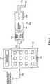
Das Sensorpaket
Obwohl das Drehmoment-aufbringende Werkzeug bislang in Bezug auf ein Werkzeug beschrieben wurde, das einen Elektromotor
Die Steuerung
Es versteht sich ferner, dass, obwohl die Steuerung
Es ist ferner darauf hinzuweisen, dass die Steuerung
Die Steuerung
ωgewünscht = (τ/t)/r, wobei Folgendes gilt:
- ωgewünscht
- = gewünschte Rotationsgeschwindigkeit des
Werkzeugs 100 , mitder das Werkzeug 100 von der Steuerung 102 angewiesen wird, bei dieser zu laufen (Grad/ms) - τ
- = finales Solldrehmoment (τF) – momentanes Drehmoment (τC) (Nm)
- t
- = Zeitkonstante der Geschwindigkeitssteuerung (ms)
- r
- = Drehmomentrate (Nm/Grad).
ωdesired = (τ / t) / r, where:
- ωdesired
- = desired rotation speed of the
tool 100 with which thetool 100 from thecontroller 102 is instructed to run at this (degrees / ms) - τ
- = final set torque (τF ) - momentary torque (τC ) (Nm)
- t
- = Time constant of the speed control (ms)
- r
- = Torque rate (Nm / degree).
Die Steuerung
Das finale Solldrehmoment (τF) kann ein durch den Nutzer eingegebenes Solldrehmoment sein, das der Nutzer in die Steuerung
Das momentane Drehmoment (τC) wird über einen Drehmomentsensor des Sensorpakets
Die Zeitkonstante (t) ist eine Funktion der Ansprechempfindlichkeit des Werkzeugs
Gemäß verschiedenen nicht-limitierenden Ausführungsbeispielen hängt die Zeitkonstante (t) von dem Motor
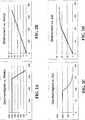
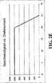
In dem in
Die Drehmomentrate (r) bezieht sich auf eine Veränderung des Drehmoments pro bzw. bezogen auf eine Veränderung des Befestigungsrotationswinkels und hängt von der zu schaffenden Verbindung ab. Eine weiche Verbindung weist eine niedrigere Drehmomentrate auf als eine harte Verbindung. Die Drehmomentrate (r) kann vor oder während jedem Befestigungszyklus bestimmt werden. Für einen bekannten Typ eines Befestigungszyklus kann die Drehmomentrate (r) empirisch von einem oder mehreren Befestigungszyklen abgeleitet werden. Solche empirischen Daten können mit Befestigungszyklusdaten für jeden neuen vergleichbaren Befestigungszyklus kombiniert werden, um so die Drehmomentrate (r) mit jedem neuen Zyklus zu aktualisieren/verbessern.The torque rate (r) refers to a change in the torque per or relative to a change in the fastening rotation angle and depends on the connection to be created. A soft connection has a lower torque rate than a hard connection. The torque rate (r) can be determined before or during each mounting cycle. For a known type of mounting cycle, the torque rate (r) may be derived empirically from one or more mounting cycles. Such empirical data can be combined with fixture cycle data for each new comparable fixture cycle so as to update / improve the torque rate (r) with each new cycle.
Alternativ kann die Drehmomentrate (r) während einer frühen Drehmomentperiode innerhalb eines jeden Befestigungszyklus berechnet werden, und zwar entweder (1) bevor der Drehmomentsteuerungsalgorithmus verwendet wird (z. B. während einer initialen Periode, in der das Werkzeug
Alternativ kann die Drehmomentrate (r) unmittelbar während des gesamten oder während eines vorbestimmten Teils eines jeden Befestigungszyklus berechnet werden. Zum Beispiel kann die Drehmomentrate (r) durch die Methode der kleinsten Quadrate berechnet werden, um die momentane Steigung in dem Diagramm von Drehmoment v. Winkel zu bestimmen, z. B. wie in
Gemäß verschiedenen Ausführungsbeispielen wird der Geschwindigkeitssteuernde Algorithmus der Steuerung
Als ein Ergebnis lässt die Steuerung
Gemäß verschiedenen Ausführungsbeispielen kann der Geschwindigkeitssteuernde Algorithmus der Steuerung
ωgewünscht fällt deshalb von auf 0, wenn τ = 0 gilt (d. h. wenn das finale Solldrehmoment (τF) = dem momentanen Drehmoment (τC) ist). Gemäß verschiedenen Ausführungsbeispielen kann ωmin ein vorbestimmter prozentualer Anteil der Nenngeschwindigkeit ωmax des Werkzeugs
Wenn sowohl die maximale freie Geschwindigkeit als auch die minimale Geschwindigkeit in den Algorithmus inkorporiert werden, lautet der Algorithmus wie folgt:
Gemäß einem oder mehreren Ausführungsbeispielen führt die Steuerung
Die vorstehend illustrierten Ausführungsbeispiele werden bereitgestellt, um die strukturellen und funktionellen Prinzipien von Ausführungsbeispielen der vorliegenden Erfindung zu illustrieren, und sind nicht als limitierend zu verstehen. Im Gegenteil, die Prinzipien der vorliegenden Erfindung sind dazu vorgesehen, um jede und alle Veränderungen, Abwandlungen und/oder Substitutionen im Rahmen des Geistes und Umfangs der folgenden Ansprüche zu erfassen.The embodiments illustrated above are provided to illustrate the structural and functional principles of embodiments of the present invention, and are not to be considered as limiting. On the contrary, the principles of the present invention are intended to cover any and all modifications, alterations, and / or substitutions within the spirit and scope of the following claims.
ZITATE ENTHALTEN IN DER BESCHREIBUNG QUOTES INCLUDE IN THE DESCRIPTION
Diese Liste der vom Anmelder aufgeführten Dokumente wurde automatisiert erzeugt und ist ausschließlich zur besseren Information des Lesers aufgenommen. Die Liste ist nicht Bestandteil der deutschen Patent- bzw. Gebrauchsmusteranmeldung. Das DPMA übernimmt keinerlei Haftung für etwaige Fehler oder Auslassungen.This list of the documents listed by the applicant has been generated automatically and is included solely for the better information of the reader. The list is not part of the German patent or utility model application. The DPMA assumes no liability for any errors or omissions.
Zitierte PatentliteraturCited patent literature
- US 5215270[0004]US 5215270[0004]
- US 5315501[0004]US 5315501[0004]
- US 5519614[0004]US 5519614[0004]
- US 5637968[0004]US 5637968[0004]
- US 5650574[0004]US 5650574[0004]
- US 6516896[0004]US 6516896[0004]
Claims (17)
Translated fromGermanApplications Claiming Priority (2)
| Application Number | Priority Date | Filing Date | Title |
|---|---|---|---|
| US13/633,639US9022135B2 (en) | 2012-10-02 | 2012-10-02 | Torque-applying tool and torque controller therefor |
| US13/633,639 | 2012-10-02 |
Publications (1)
| Publication Number | Publication Date |
|---|---|
| DE102013015139A1true DE102013015139A1 (en) | 2014-04-03 |
Family
ID=50276390
Family Applications (1)
| Application Number | Title | Priority Date | Filing Date |
|---|---|---|---|
| DE201310015139PendingDE102013015139A1 (en) | 2012-10-02 | 2013-09-13 | Tool for applying a torque and torque control therefor |
Country Status (3)
| Country | Link |
|---|---|
| US (1) | US9022135B2 (en) |
| DE (1) | DE102013015139A1 (en) |
| FR (1) | FR2996317B1 (en) |
Cited By (2)
| Publication number | Priority date | Publication date | Assignee | Title |
|---|---|---|---|---|
| DE102017108325A1 (en)* | 2017-04-19 | 2018-10-25 | Schunk Gmbh & Co. Kg Spann- Und Greiftechnik | Linear, gripping, clamping, rotating or pivoting device, method for operating such a device, and device for evaluating such a device |
| CN111421492A (en)* | 2020-04-27 | 2020-07-17 | 深圳市威富智能设备有限公司 | Electric screwdriver and sectional control method and storage medium thereof |
Families Citing this family (7)
| Publication number | Priority date | Publication date | Assignee | Title |
|---|---|---|---|---|
| CN105899332B (en)* | 2013-12-20 | 2017-10-31 | 阿特拉斯·科普柯工业技术公司 | Power tool for tightening a fastener and method |
| US20150332327A1 (en)* | 2014-05-13 | 2015-11-19 | Sony Corporation | Retail store audio video feature demonstration system |
| CN107407925B (en)* | 2014-12-15 | 2019-08-20 | 艾沛克斯品牌公司 | Convertible intelligent power tool |
| US10357871B2 (en) | 2015-04-28 | 2019-07-23 | Milwaukee Electric Tool Corporation | Precision torque screwdriver |
| KR200490007Y1 (en) | 2015-04-28 | 2019-11-04 | 밀워키 일렉트릭 툴 코포레이션 | Precision torque screwdriver |
| US11752604B2 (en) | 2018-04-13 | 2023-09-12 | Snap-On Incorporated | System and method for measuring torque and angle |
| EP4192657A4 (en) | 2020-08-10 | 2024-11-13 | Milwaukee Electric Tool Corporation | Powered screwdriver including clutch setting sensor |
Citations (6)
| Publication number | Priority date | Publication date | Assignee | Title |
|---|---|---|---|---|
| US5215270A (en) | 1992-06-18 | 1993-06-01 | Cooper Industries, Inc. | Method for tightening a fastener |
| US5315501A (en) | 1992-04-03 | 1994-05-24 | The Stanley Works | Power tool compensator for torque overshoot |
| US5519614A (en) | 1992-09-22 | 1996-05-21 | Mitsubishi Jidosha Kogyo Kabushiki Kaisha | Electronically controlled power steering apparatus and method therefor |
| US5637968A (en) | 1993-10-25 | 1997-06-10 | The Stanley Works | Power tool with automatic downshift feature |
| US5650574A (en) | 1995-07-11 | 1997-07-22 | Quantai Systems Inc, | Method of tightening a bolt with an optimum time |
| US6516896B1 (en) | 2001-07-30 | 2003-02-11 | The Stanley Works | Torque-applying tool and control therefor |
Family Cites Families (12)
| Publication number | Priority date | Publication date | Assignee | Title |
|---|---|---|---|---|
| US4344216A (en)* | 1979-12-10 | 1982-08-17 | Sps Technologies, Inc. | Apparatus and method for tightening an assembly |
| US4894767A (en)* | 1988-03-31 | 1990-01-16 | Daiichi Dentsu Kabushiki Kaisha | Method for yield tightening of screws |
| JP2647480B2 (en)* | 1989-02-10 | 1997-08-27 | マツダ株式会社 | Screw tightening method |
| US4995145A (en)* | 1990-01-08 | 1991-02-26 | Allen-Bradley Company, Inc. | Reduction of relaxation induced tension scatter in fasteners |
| US5212862A (en)* | 1990-10-09 | 1993-05-25 | Allen-Bradley Company, Inc. | Torque-angle window control for threaded fasteners |
| GB9320181D0 (en)* | 1993-09-30 | 1993-11-17 | Black & Decker Inc | Improvements in and relating to power tools |
| JPH08294875A (en)* | 1995-04-25 | 1996-11-12 | Nissan Motor Co Ltd | Impact type screw tightening device |
| SE513563C2 (en)* | 1998-03-19 | 2000-10-02 | Atlas Copco Tools Ab | Method for self-programming control systems for power nuts during initial tightening procedures |
| US6430463B1 (en)* | 2000-02-29 | 2002-08-06 | O.E. Electronics, Inc. | Torque control |
| US6783591B1 (en)* | 2002-08-06 | 2004-08-31 | Advanced Micro Devices, Inc. | Laser thermal annealing method for high dielectric constant gate oxide films |
| SE526964C2 (en)* | 2003-12-29 | 2005-11-29 | Atlas Copco Tools Ab | Method for functional control of a pneumatic pulse nut puller and a power screwdriver system |
| JP4203459B2 (en)* | 2004-08-30 | 2009-01-07 | 日東工器株式会社 | Electric driver device |
- 2012
- 2012-10-02USUS13/633,639patent/US9022135B2/enactiveActive
- 2013
- 2013-09-13DEDE201310015139patent/DE102013015139A1/enactivePending
- 2013-09-30FRFR1359437Apatent/FR2996317B1/enactiveActive
Patent Citations (6)
| Publication number | Priority date | Publication date | Assignee | Title |
|---|---|---|---|---|
| US5315501A (en) | 1992-04-03 | 1994-05-24 | The Stanley Works | Power tool compensator for torque overshoot |
| US5215270A (en) | 1992-06-18 | 1993-06-01 | Cooper Industries, Inc. | Method for tightening a fastener |
| US5519614A (en) | 1992-09-22 | 1996-05-21 | Mitsubishi Jidosha Kogyo Kabushiki Kaisha | Electronically controlled power steering apparatus and method therefor |
| US5637968A (en) | 1993-10-25 | 1997-06-10 | The Stanley Works | Power tool with automatic downshift feature |
| US5650574A (en) | 1995-07-11 | 1997-07-22 | Quantai Systems Inc, | Method of tightening a bolt with an optimum time |
| US6516896B1 (en) | 2001-07-30 | 2003-02-11 | The Stanley Works | Torque-applying tool and control therefor |
Cited By (3)
| Publication number | Priority date | Publication date | Assignee | Title |
|---|---|---|---|---|
| DE102017108325A1 (en)* | 2017-04-19 | 2018-10-25 | Schunk Gmbh & Co. Kg Spann- Und Greiftechnik | Linear, gripping, clamping, rotating or pivoting device, method for operating such a device, and device for evaluating such a device |
| CN111421492A (en)* | 2020-04-27 | 2020-07-17 | 深圳市威富智能设备有限公司 | Electric screwdriver and sectional control method and storage medium thereof |
| CN111421492B (en)* | 2020-04-27 | 2022-08-05 | 深圳市威富智能设备有限公司 | Electric screwdriver and sectional control method and storage medium thereof |
Also Published As
| Publication number | Publication date |
|---|---|
| US20140090224A1 (en) | 2014-04-03 |
| US9022135B2 (en) | 2015-05-05 |
| FR2996317A1 (en) | 2014-04-04 |
| FR2996317B1 (en) | 2018-03-23 |
Similar Documents
| Publication | Publication Date | Title |
|---|---|---|
| DE102013015139A1 (en) | Tool for applying a torque and torque control therefor | |
| DE102011122212B4 (en) | Battery-powered screwing system with reduced radio-transmitted data volume | |
| DE102009047443B4 (en) | Hand tool machine | |
| DE202013100915U1 (en) | Impact wrench with adjustable torque | |
| DE102016115538A1 (en) | Rotary impact tool and method for controlling the same | |
| DE102017119623B4 (en) | Torque control system and torque control method for electric shock with adjustable torque | |
| EP3113911B1 (en) | Adaptive power indicator | |
| DE102015011535A1 (en) | Trajectory display device for displaying engine end and machine end trajectories | |
| EP3571017A1 (en) | Method and device for tightening screw joints | |
| EP3856462B1 (en) | Method for controlling or regulating a hand-held power tool | |
| DE102008054455A1 (en) | Orientation sensor for orientation controller, has sensor unit for detecting actual orientation or orientation deviation from orientation, where evaluation unit is connected with sensor unit | |
| DE112017005671B4 (en) | ELECTRIC MOTOR-DRIVEN TOOL AND CONTROL DEVICE AND CONTROL CIRCUIT THEREFOR | |
| DE102013221790A1 (en) | Rivet attachment for a screwing tool and screwing tool | |
| AT509381B1 (en) | TEST STATION FOR DYNAMIC TEST TESTS ON INTERNAL COMBUSTION ENGINES, AND METHOD FOR OPERATING SUCH TEST STATION | |
| DE102014105667A1 (en) | Turntable with tightening torque measuring device | |
| DE102016011768A1 (en) | Battery system with bidirectional wireless communication | |
| DE102012100928B4 (en) | Motor drive control device that adjusts the power output of a motor depending on the delivery behavior of an AC power supply | |
| EP0187353A2 (en) | Power-driven screwing device with torque limitation | |
| DE102013016770B4 (en) | A motor control device for controlling a plurality of motors that drive a driven body | |
| DE102005058038B3 (en) | Method and control device for determining the time until necessary maintenance of a machine element | |
| DE112019005777T5 (en) | Turning tool | |
| DE102018213370A1 (en) | Method for determining a temperature of an electric motor of a machine tool and machine tool | |
| DE102018202115A1 (en) | Robot module, type-specific floor panel, and method of performing work in a vehicle interior when manufacturing a vehicle on an assembly line | |
| WO2016113029A1 (en) | Regulation of a drive device | |
| DE102023200619A1 (en) | Method for selecting data for training an artificial intelligence, method for generating a training data set, training data set |
Legal Events
| Date | Code | Title | Description |
|---|---|---|---|
| R082 | Change of representative | Representative=s name:WITTE, WELLER & PARTNER PATENTANWAELTE MBB, DE | |
| R012 | Request for examination validly filed |