DE102013011609B4 - Air filter element and this containing air filter - Google Patents
Air filter element and this containing air filterDownload PDFInfo
- Publication number
- DE102013011609B4 DE102013011609B4DE102013011609.0ADE102013011609ADE102013011609B4DE 102013011609 B4DE102013011609 B4DE 102013011609B4DE 102013011609 ADE102013011609 ADE 102013011609ADE 102013011609 B4DE102013011609 B4DE 102013011609B4
- Authority
- DE
- Germany
- Prior art keywords
- air filter
- sealing
- filter element
- shaped
- housing
- Prior art date
- Legal status (The legal status is an assumption and is not a legal conclusion. Google has not performed a legal analysis and makes no representation as to the accuracy of the status listed.)
- Active
Links
- 238000007789sealingMethods0.000claimsabstractdescription99
- 239000004033plasticSubstances0.000claimsabstractdescription22
- 229920003023plasticPolymers0.000claimsabstractdescription22
- 230000007704transitionEffects0.000claimsabstractdescription4
- 239000004433Thermoplastic polyurethaneSubstances0.000claimsdescription8
- 229920002803thermoplastic polyurethanePolymers0.000claimsdescription8
- 239000000463materialSubstances0.000claimsdescription5
- 229920002725thermoplastic elastomerPolymers0.000claimsdescription3
- 238000002485combustion reactionMethods0.000description4
- 238000001914filtrationMethods0.000description2
- 238000003780insertionMethods0.000description2
- 230000037431insertionEffects0.000description2
- 229920005830Polyurethane FoamPolymers0.000description1
- 230000001174ascending effectEffects0.000description1
- 238000013016dampingMethods0.000description1
- 230000001419dependent effectEffects0.000description1
- 238000011161developmentMethods0.000description1
- 230000018109developmental processEffects0.000description1
- 230000000694effectsEffects0.000description1
- 239000006260foamSubstances0.000description1
- 238000012423maintenanceMethods0.000description1
- 230000000241respiratory effectEffects0.000description1
- 239000011265semifinished productSubstances0.000description1
Images


Classifications
- B—PERFORMING OPERATIONS; TRANSPORTING
- B01—PHYSICAL OR CHEMICAL PROCESSES OR APPARATUS IN GENERAL
- B01D—SEPARATION
- B01D46/00—Filters or filtering processes specially modified for separating dispersed particles from gases or vapours
- B01D46/0002—Casings; Housings; Frame constructions
- B01D46/0005—Mounting of filtering elements within casings, housings or frames
- B—PERFORMING OPERATIONS; TRANSPORTING
- B01—PHYSICAL OR CHEMICAL PROCESSES OR APPARATUS IN GENERAL
- B01D—SEPARATION
- B01D46/00—Filters or filtering processes specially modified for separating dispersed particles from gases or vapours
- B01D46/10—Particle separators, e.g. dust precipitators, using filter plates, sheets or pads having plane surfaces
- B—PERFORMING OPERATIONS; TRANSPORTING
- B01—PHYSICAL OR CHEMICAL PROCESSES OR APPARATUS IN GENERAL
- B01D—SEPARATION
- B01D46/00—Filters or filtering processes specially modified for separating dispersed particles from gases or vapours
- B01D46/52—Particle separators, e.g. dust precipitators, using filters embodying folded corrugated or wound sheet material
- B01D46/521—Particle separators, e.g. dust precipitators, using filters embodying folded corrugated or wound sheet material using folded, pleated material
- B—PERFORMING OPERATIONS; TRANSPORTING
- B01—PHYSICAL OR CHEMICAL PROCESSES OR APPARATUS IN GENERAL
- B01D—SEPARATION
- B01D2271/00—Sealings for filters specially adapted for separating dispersed particles from gases or vapours
- B01D2271/02—Gaskets, sealings
- B—PERFORMING OPERATIONS; TRANSPORTING
- B01—PHYSICAL OR CHEMICAL PROCESSES OR APPARATUS IN GENERAL
- B01D—SEPARATION
- B01D2271/00—Sealings for filters specially adapted for separating dispersed particles from gases or vapours
- B01D2271/02—Gaskets, sealings
- B01D2271/022—Axial sealings
Landscapes
- Chemical & Material Sciences (AREA)
- Chemical Kinetics & Catalysis (AREA)
- Filtering Of Dispersed Particles In Gases (AREA)
Abstract
Translated fromGermanDescription
Translated fromGermanTechnisches GebietTechnical area
Die Erfindung bezieht sich auf ein Luftfilterelement nach dem Oberbegriff des Anspruches 1.The invention relates to an air filter element according to the preamble of
Stand der TechnikState of the art
Aus der
Für eine sichere Verbindung des Dichtungselementes am Filterelement sind in das Filterelement benachbart zur Seitenkante rillenförmige Vertiefungen eingebracht, in die das Dichtungselement eingespritzt ist.For a secure connection of the sealing element on the filter element groove-shaped recesses are introduced into the filter element adjacent to the side edge into which the sealing element is injected.
Offenbarung der ErfindungDisclosure of the invention
Der Erfindung liegt die Aufgabe zugrunde, mit einfachen konstruktiven Maßnahmen die Reinseite von der Rohseite eines Luftfilterelementes strömungsdicht zu separieren.The invention is based on the object with simple structural measures to separate the clean side of the raw side of an air filter element fluid-tight.
Diese Aufgabe wird erfindungsgemäß mit den Merkmalen des Anspruches 1 gelöst. Die Unteransprüche geben zweckmäßige Weiterbildungen an.This object is achieved with the features of
Das erfindungsgemäße Luftfilterelement wird in einem Luftfilter eingesetzt, das beispielsweise in den Ansaugtrakt einer Brennkraftmaschine integriert ist. Möglich sind aber auch Anwendungen von Luftfiltern in anderen technischen Gebieten, beispielsweise zur Reinigung der Atemluft in Fahrzeug- oder Flugzeugkabinen.The air filter element according to the invention is used in an air filter, which is integrated, for example, in the intake of an internal combustion engine. However, it is also possible to use air filters in other technical fields, for example for purifying respiratory air in vehicle or aircraft cabins.
Das Luftfilterelement weist ein plattenförmiges Filtermittel auf, welches von der zu reinigenden Luft durchströmt wird. Das Filtermittel ist von einem Kunststoffrahmen eingefasst, an dem ein umlaufendes Dichtungselement angeordnet ist. Zweckmäßigerweise läuft auch der Kunststoffrahmen am Filtermittel des Filterelementes um und umschließt das Filterelement. Gemäß einer weiteren zweckmäßigen Ausführung ist das Dichtungselement ausschließlich an dem Kunststoffrahmen gehalten, wobei auch Ausführungen möglich sind, bei denen das Dichtungselement nicht nur am Kunststoffrahmen, sondern zusätzlich auch unmittelbar am Filtermittel anliegt und von diesem gehalten wird.The air filter element has a plate-shaped filter medium, which is flowed through by the air to be cleaned. The filter means is bordered by a plastic frame, on which a circumferential sealing element is arranged. Expediently, the plastic frame also runs around the filter element of the filter element and surrounds the filter element. According to a further expedient embodiment, the sealing element is held exclusively on the plastic frame, whereby embodiments are possible in which the sealing element rests not only on the plastic frame, but in addition also directly on the filter means and is held by this.
Am Kunststoffrahmen ist eine seitlich nach außen, vom Filtermittel weg weisende Kante angeordnet, die von einem Abschnitt des Dichtungselements U-förmig umgriffen ist. Des Weiteren ist einteilig mit dem Dichtungselement eine umlaufende Dichtlippe ausgebildet, die an einem Seitenschenkel des U-förmigen Abschnitts angeordnet ist und sich über den Seitenschenkel erhebt.On the plastic frame, a laterally outwardly, away from the filter means edge is arranged, which is embraced by a portion of the sealing element U-shaped. Furthermore, an encircling sealing lip is formed in one piece with the sealing element, which is arranged on a side limb of the U-shaped section and rises above the side limb.
Mit dieser Ausführung werden verschiedene Vorteile erzielt. Zum einen ist eine feste und dauerhafte Verbindung zwischen dem Dichtungselement und dem Kunststoffrahmen und damit auch zum Filtermittel gegeben. Der U-förmige Abschnitt umgreift die Kante am Kunststoffrahmen mechanisch formschlüssig, gegebenenfalls auch chemisch stoffschlüssig, und ist sicher am Kunststoffrahmen gehalten. Zum anderen bildet ein Seitenschenkel des U-förmigen Abschnittes eine Dicht- bzw. Auflagefläche, mit der das Dichtungselement an der Wandung des aufnehmenden Filtergehäuses elastisch nachgiebig anliegt. Dies verbessert zum einen die Dichtwirkung, zum anderen werden Kräfte bei der Montage mit dem Einsetzen des Filterelementes in das Filtergehäuse und dem Aufsetzen eines Gehäusedeckels durch die Elastizität des Dämpfungsmaterials gedämpft. Hierbei liegt die umlaufende Dichtlippe an der Innenseite des Gehäusedeckels an, welcher auf das Filtergehäuse aufgesetzt wird. Der U-förmige Dichtabschnitt und die Dichtlippe, welche einteilig mit dem U-förmigen Dichtabschnitt ausgebildet ist, sorgen für eine Reduzierung der Kräfte beim Aufsetzen und Schließen des Gehäusedeckels auf das Filtergehäuse. Das Dichtungselement weist zugleich eine einfache Querschnittsgeometrie auf und lässt sich entsprechend einfach herstellen.With this embodiment, various advantages are achieved. On the one hand, there is a firm and permanent connection between the sealing element and the plastic frame and thus also to the filter medium. The U-shaped section surrounds the edge of the plastic frame mechanically form-fitting, optionally also chemically cohesively, and is securely held on the plastic frame. On the other hand, a side leg of the U-shaped section forms a sealing or bearing surface with which the sealing element rests elastically yielding on the wall of the receiving filter housing. This improves on the one hand the sealing effect, on the other hand forces are damped during assembly with the insertion of the filter element into the filter housing and the placement of a housing cover by the elasticity of the damping material. Here, the circumferential sealing lip on the inside of the housing cover, which is placed on the filter housing. The U-shaped sealing portion and the sealing lip, which is formed integrally with the U-shaped sealing portion, provide for a reduction in the forces when placing and closing the housing cover on the filter housing. The sealing element at the same time has a simple cross-sectional geometry and can be correspondingly easily manufactured.
Gemäß einer vorteilhaften Ausführung wird das Dichtungselement an die nach außen ragende Kante des Kunststoffrahmens angespritzt. Als Material für das Dichtungselement kommt beispielsweise TPU (thermoplastische Polyurethane) oder TPV (vernetzte thermoplastische Elastomere) in Betracht. Die TPU bzw. TPV können ggf. in einem geschäumten Zustand vorliegen. Die Schaumstruktur kann eine geschlossene Oberfläche aufweisen.According to an advantageous embodiment, the sealing element is molded onto the outwardly projecting edge of the plastic frame. The material used for the sealing element is, for example, TPU (thermoplastic polyurethanes) or TPV ( crosslinked thermoplastic elastomers) into consideration. The TPU or TPV may possibly be present in a foamed state. The foam structure may have a closed surface.
Im Unterschied zu einem PU-Schaum, welcher beim Schließen des Gehäusedeckels verpresst werden muss, um die Dichtungsanforderungen zu erfüllen, was mit hohen Schließkräften einhergeht, werden bei der erfindungsgemäßen Ausführung des Dichtungselementes aufgrund der geometrischen Ausführung mit U-förmigem Dichtabschnitt und angeformter Dichtlippe in Verbindung mit dem TPU- oder TPV-Material des Dichtungselementes die zum Schließen des Gehäusedeckels erforderlichen Kräfte erheblich reduziert. Dies vereinfacht den Zusammenbau des Luftfilters sowie den Wechsel des Luftfilterelementes im Wartungsfall.In contrast to a PU foam, which must be pressed when closing the housing cover to meet the sealing requirements, which is associated with high closing forces are in the inventive design of the sealing element due to the geometric design with U-shaped sealing portion and molded sealing lip in combination with the TPU or TPV material of the sealing element considerably reduces the forces required to close the housing cover. This simplifies the assembly of the air filter and the replacement of the air filter element in case of maintenance.
Die einteilig ausgebildete Dichtlippe bietet zudem einen großen Toleranzausgleich, so dass Gehäusetoleranzen besser kompensiert werden können.The integrally formed sealing lip also offers a large tolerance compensation, so that housing tolerances can be better compensated.
Die Dichtlippe nimmt, gemäß einer weiteren zweckmäßigen Ausführung, gegenüber einer Orthogonalen zur Ebene des Seitenschenkels des U-förmigen Abschnittes einen Winkel ein, der zweckmäßigerweise mindestens 15° beträgt. Die Seitenschenkel erstrecken sich der Kontur der Kante des Kunststoffrahmens folgend in Querrichtung, bezogen auf die Wandebene des Filtergehäuses. Die Orthogonale zur Ebene der Seitenschenkel verläuft dementsprechend parallel zur Wandebene der Wandung des Filtergehäuses. Die Dichtlippe nimmt somit im unverformten Zustand einen Winkel von mindestens 15° gegenüber der Ebene der Wandung des Filtergehäuses ein. Der Winkel liegt beispielsweise in einem Bereich zwischen 15° und 60°, wobei ggf. auch eine orthogonale Erstreckung der Dichtlippe zum Seitenschenkel in Betracht kommt, also eine Erstreckung parallel zur Wandebene der Wandung des Filtergehäuses. Bei winkliger Ausführung der Dichtlippe ist mit dem Aufsetzen des Gehäusedeckels die Verformungsrichtung der Dichtlippe eindeutig bestimmt. Die Dichtlippe erstreckt sich zweckmäßigerweise im unverformten Zustand mit ihrer freien Stirnseite mit einer Richtungskomponente nach außen, so dass mit dem Aufsetzen des Gehäusedeckels eine Verformung der Dichtlippe nach außen erfolgt.The sealing lip takes, according to another expedient embodiment, opposite to an orthogonal to the level of the side leg of the U-shaped portion an angle, which is expediently at least 15 °. The side legs extend the contour of the edge of the plastic frame following in the transverse direction, based on the wall plane of the filter housing. The orthogonal to the plane of the side legs runs correspondingly parallel to the wall plane of the wall of the filter housing. The sealing lip thus assumes an angle of at least 15 ° relative to the plane of the wall of the filter housing in the undeformed state. The angle is, for example, in a range between 15 ° and 60 °, wherein optionally also an orthogonal extent of the sealing lip to the side leg comes into consideration, ie an extension parallel to the wall plane of the wall of the filter housing. With angled design of the sealing lip, the deformation direction of the sealing lip is uniquely determined by placing the housing cover. The sealing lip expediently extends in the undeformed state with its free end face with a directional component to the outside, so that with the placement of the housing cover, a deformation of the sealing lip to the outside.
Das Luftfilterelement kann mehreckig, vorzugsweise rechteckförmig und als Plattenfilter ausgeführt sein. In Betracht kommen auch nicht-eckige Ausführungen, beispielsweise runde Luftfilterelemente.The air filter element may be polygonal, preferably rectangular and designed as a plate filter. Also contemplated are non-angular designs, such as round air filter elements.
Das Filtermittel kann als ein Faltenfilter ausgeführt sein. Die Dichtlippe erstreckt sich entlang der geradlinigen oder gekrümmten Seiten des Luftfilterelements und weist erfindungsgemäß im Übergang zwischen zwei winklig aneinandergrenzenden Seiten einen verlängert ausgeführten Kompensationsabschnitt auf. Der Kompensationsabschnitt ist vorteilhafterweise teilkreisförmig, ggf. elliptisch oder bogenförmig ausgebildet und verbindet winklig aneinandergrenzende, geradlinige oder gekrümmte Dichtlippenabschnitte an unterschiedlichen Seiten miteinander. Der verlängerte Kompensationsabschnitt ermöglicht es, dass die Dichtlippenabschnitte an den verschiedenen Seiten jeweils bei Beaufschlagung durch den Gehäusedeckel nach außen gedrückt werden; hierbei verlängert sich der Kompensationsabschnitt, so dass trotz der nach außen umgebogenen Dichtlippe eine durchgehende und strömungsdichte Verbindung zwischen dem Dichtungselement und dem aufliegenden Gehäusedeckel gebildet ist.The filter means may be designed as a pleated filter. The sealing lip extends along the straight or curved sides of the air filter element and, according to the invention, has an extended compensating section in the transition between two adjoining sides at an angle. The compensation section is advantageously part-circular, optionally elliptical or arc-shaped, and connects at an angle to each other adjacent, straight or curved sealing lip sections on different sides. The extended compensating portion allows the sealing lip portions on the different sides to be urged outward respectively when urged by the housing cover; In this case, the compensation section extends, so that despite the outwardly bent sealing lip a continuous and flow-tight connection between the sealing element and the overlying housing cover is formed.
Der Luftfilter umfasst das Luftfilterelement und ein Filtergehäuse, in das das Luftfilterelement eingesetzt wird. Das Filtergehäuse ist von dem Gehäusedeckel zu verschließen. Das Dichtungselement liegt mit einem der Seitenschenkel des U-förmigen Abschnitts an dem Filtergehäuse und mit der Dichtlippe am Gehäusedeckel an. Gemäß einer zweckmäßigen Ausführung besitzt das Filtergehäuse benachbart zu seiner Stirnseite eine seitlich auskragende Stützschulter, auf der im montierten Zustand ein Seitenschenkel des U-förmigen Dichtabschnittes aufliegt. Die Stützschulter nimmt auch die Schließkräfte bei aufgesetztem Gehäusedeckel auf. Die Stützschulter weist zweckmäßigerweise an ihrer radial außen liegenden Seite eine begrenzende, aufgestellte Wandung auf, an deren Innenseite das Dichtungselement anliegt.The air filter includes the air filter element and a filter housing into which the air filter element is inserted. The filter housing is to be closed by the housing cover. The sealing element abuts one of the side legs of the U-shaped section on the filter housing and with the sealing lip on the housing cover. According to an expedient embodiment, the filter housing adjacent to its end face has a laterally projecting support shoulder on which a side leg of the U-shaped sealing portion rests in the mounted state. The support shoulder also absorbs the closing forces with the housing cover attached. The support shoulder has expediently on its radially outer side a limiting, erected wall, against the inside of the sealing element.
Grundsätzlich kommt auch eine umgekehrte Ausführung in Betracht, bei der das Dichtungselement mit einem der Seitenschenkel des U-förmigen Abschnitts an dem Gehäusedeckel und mit der Dichtlippe am Filtergehäuse anliegt.In principle, a reverse embodiment into consideration, in which the sealing element rests with one of the side legs of the U-shaped portion on the housing cover and with the sealing lip on the filter housing.
Kurze Beschreibung der ZeichnungenBrief description of the drawings
Weitere Vorteile und zweckmäßige Ausführungen sind den weiteren Ansprüchen, der Figurenbeschreibung und den Zeichnungen zu entnehmen. Es zeigen:Further advantages and expedient embodiments can be taken from the further claims, the description of the figures and the drawings. Show it:
In den Figuren sind gleiche Bauteile mit gleichen Bezugszeichen versehen.In the figures, the same components are provided with the same reference numerals.
Ausführungsformen der ErfindungEmbodiments of the invention
In
Wie
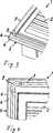
Wie den
In den
In
Wie der Schnittdarstellung gemäß
Claims (10)
Translated fromGermanPriority Applications (4)
| Application Number | Priority Date | Filing Date | Title |
|---|---|---|---|
| DE102013011609.0ADE102013011609B4 (en) | 2013-07-12 | 2013-07-12 | Air filter element and this containing air filter |
| IN2195MU2014IN2014MU02195A (en) | 2013-07-12 | 2014-07-07 | |
| CN201410329757.5ACN104275057B (en) | 2013-07-12 | 2014-07-11 | Air filter element |
| US14/330,029US9409112B2 (en) | 2013-07-12 | 2014-07-14 | Air filter element |
Applications Claiming Priority (1)
| Application Number | Priority Date | Filing Date | Title |
|---|---|---|---|
| DE102013011609.0ADE102013011609B4 (en) | 2013-07-12 | 2013-07-12 | Air filter element and this containing air filter |
Publications (2)
| Publication Number | Publication Date |
|---|---|
| DE102013011609A1 DE102013011609A1 (en) | 2015-01-15 |
| DE102013011609B4true DE102013011609B4 (en) | 2017-08-17 |
Family
ID=52107058
Family Applications (1)
| Application Number | Title | Priority Date | Filing Date |
|---|---|---|---|
| DE102013011609.0AActiveDE102013011609B4 (en) | 2013-07-12 | 2013-07-12 | Air filter element and this containing air filter |
Country Status (4)
| Country | Link |
|---|---|
| US (1) | US9409112B2 (en) |
| CN (1) | CN104275057B (en) |
| DE (1) | DE102013011609B4 (en) |
| IN (1) | IN2014MU02195A (en) |
Families Citing this family (26)
| Publication number | Priority date | Publication date | Assignee | Title |
|---|---|---|---|---|
| US8061530B2 (en) | 2009-04-09 | 2011-11-22 | Cummins Filtration Ip, Inc. | Filtration sealing system |
| DE102014013280A1 (en)* | 2014-09-12 | 2016-03-17 | Mann + Hummel Gmbh | Filter device for gas filtration and filter element for a filter device for gas filtration |
| DE102014013278A1 (en)* | 2014-09-12 | 2016-03-17 | Mann + Hummel Gmbh | Plate-shaped filter element for gas filtration |
| WO2016156292A1 (en) | 2015-03-31 | 2016-10-06 | Koninklijke Philips N.V. | Filter assembly and airway pressure support system employing same |
| DE102015004643A1 (en)* | 2015-04-15 | 2016-10-20 | Mann + Hummel Gmbh | Filter element, in particular for gas filtration |
| JP6779275B2 (en) | 2015-07-15 | 2020-11-04 | ボールドウィン・フィルターズ・インコーポレーテッドBaldwin Filters Inc | Multi-component holding assembly for multi-panel air filters |
| US10369508B2 (en) | 2017-02-23 | 2019-08-06 | Baldwin Filters, Inc. | Filter with shield features |
| US10974188B2 (en) | 2015-07-15 | 2021-04-13 | Baldwin Filters, Inc. | Filter with shield features |
| US12168193B2 (en) | 2015-07-15 | 2024-12-17 | Baldwin Filters, Inc. | Filter with shield features |
| DE102016213814B4 (en)* | 2015-08-03 | 2024-12-05 | Mahle International Gmbh | filter element with a frame and a filter body |
| DE112016004899T5 (en) | 2015-12-11 | 2018-07-12 | Cummins Filtration Ip, Inc. | Filter with axial seal with variable cross-section |
| DE102015226754A1 (en)* | 2015-12-28 | 2017-06-29 | Mahle International Gmbh | filtering device |
| CN105617775A (en)* | 2016-01-05 | 2016-06-01 | 浙江兄弟之星汽配有限公司 | Car air conditioner filter convenient to detach |
| WO2017160592A1 (en) | 2016-03-18 | 2017-09-21 | Cummins Filtration Ip, Inc. | Interlocked stable filter assembly |
| MX2018013103A (en)* | 2016-05-02 | 2019-03-28 | Cummins Filtration Ip Inc | Filter with interlocking housing interface. |
| KR101786345B1 (en)* | 2016-05-18 | 2017-10-18 | 현대자동차주식회사 | Air Cleaner of Air Filter using High Density Filter Paper and Vehicle thereby |
| WO2018140310A1 (en) | 2017-01-25 | 2018-08-02 | Cummins Filtration Ip, Inc. | Expandable threaded adapter for threadless shell |
| WO2018156489A1 (en) | 2017-02-21 | 2018-08-30 | Cummins Filtration Ip, Inc. | Undulated interlocking housing-endplate interface geometry |
| DE112018000692T5 (en) | 2017-03-16 | 2019-10-17 | Cummins Filtration Ip, Inc. | FILTRATION SEALING SYSTEM |
| KR102292655B1 (en) | 2017-04-26 | 2021-08-23 | 지브이에스 필트레이션, 인코포레이티드 | Multi Bead Air Filter Seal |
| KR102585171B1 (en) | 2017-08-09 | 2023-10-05 | 도날드슨 컴파니, 인코포레이티드 | Filter cartridges, air cleaner assemblies, housings, features, components, and methods |
| BE1026434B1 (en)* | 2018-06-26 | 2020-02-03 | Atlas Copco Airpower Nv | Filter device and method for mounting such filter device |
| CN112469487A (en) | 2018-07-23 | 2021-03-09 | 康明斯滤清系统公司 | Radial seal for spin-on filter |
| EP3680002A1 (en) | 2019-01-08 | 2020-07-15 | Donaldson Company, Inc. | Filter element and method for servicing a filter system |
| USD1002792S1 (en) | 2019-02-05 | 2023-10-24 | Donaldson Company, Inc. | Filter cartridge |
| CN115916375A (en) | 2020-06-22 | 2023-04-04 | 康斐尔公司 | Air filter and gasket for air filter |
Citations (4)
| Publication number | Priority date | Publication date | Assignee | Title |
|---|---|---|---|---|
| DE19508678A1 (en)* | 1994-03-11 | 1995-09-14 | Toyoda Boshoku Kk | Air filter |
| WO2005094655A2 (en)* | 2004-03-24 | 2005-10-13 | Donaldson Company, Inc. | Filter elements; air cleaner; assembly; and, methods |
| DE202007014821U1 (en)* | 2007-10-02 | 2009-02-26 | Mann+Hummel Gmbh | Filter element V-seal |
| US20090145093A1 (en)* | 2002-04-04 | 2009-06-11 | Donaldson Company, Inc. | Filter elements; air cleaner; assembly; and, methods |
Family Cites Families (5)
| Publication number | Priority date | Publication date | Assignee | Title |
|---|---|---|---|---|
| DE29904204U1 (en)* | 1999-03-09 | 1999-05-12 | Mann & Hummel Filter | Filter element for filtering liquid or gaseous media |
| US20030177745A1 (en)* | 2002-03-25 | 2003-09-25 | Jauw Tjoen Liang | Filter device securing mechanism for an air cleaner |
| EP1464372B1 (en) | 2003-04-02 | 2009-01-28 | Wix Filtration Corp LLC | Filter elements having injection molded thermoplastic seals and methods of making same |
| US20050229563A1 (en)* | 2004-04-19 | 2005-10-20 | Holzmann Mark V | Filter element |
| WO2009106588A1 (en)* | 2008-02-26 | 2009-09-03 | Mann+Hummel Gmbh | Filter device, in particular air filter for an internal combustion engine |
- 2013
- 2013-07-12DEDE102013011609.0Apatent/DE102013011609B4/enactiveActive
- 2014
- 2014-07-07ININ2195MU2014patent/IN2014MU02195A/enunknown
- 2014-07-11CNCN201410329757.5Apatent/CN104275057B/ennot_activeExpired - Fee Related
- 2014-07-14USUS14/330,029patent/US9409112B2/ennot_activeExpired - Fee Related
Patent Citations (4)
| Publication number | Priority date | Publication date | Assignee | Title |
|---|---|---|---|---|
| DE19508678A1 (en)* | 1994-03-11 | 1995-09-14 | Toyoda Boshoku Kk | Air filter |
| US20090145093A1 (en)* | 2002-04-04 | 2009-06-11 | Donaldson Company, Inc. | Filter elements; air cleaner; assembly; and, methods |
| WO2005094655A2 (en)* | 2004-03-24 | 2005-10-13 | Donaldson Company, Inc. | Filter elements; air cleaner; assembly; and, methods |
| DE202007014821U1 (en)* | 2007-10-02 | 2009-02-26 | Mann+Hummel Gmbh | Filter element V-seal |
Also Published As
| Publication number | Publication date |
|---|---|
| IN2014MU02195A (en) | 2015-10-09 |
| US9409112B2 (en) | 2016-08-09 |
| DE102013011609A1 (en) | 2015-01-15 |
| US20150013293A1 (en) | 2015-01-15 |
| CN104275057B (en) | 2018-10-23 |
| CN104275057A (en) | 2015-01-14 |
Similar Documents
| Publication | Publication Date | Title |
|---|---|---|
| DE102013011609B4 (en) | Air filter element and this containing air filter | |
| DE102014016908B4 (en) | Filter element with filter bellows, filter system and use of the filter system | |
| DE112013003032B4 (en) | Cabin filter and filter element for a cabin filter | |
| DE102012019320B4 (en) | Support device of a filter, flat filter element of a filter and filter | |
| DE102009037999B4 (en) | Filter device, in particular air filter | |
| DE102015011339B4 (en) | Filter element with a circumferential seal and process for its manufacture | |
| DE102013019327B4 (en) | Filter element with filter bellows and use of the filter element | |
| DE102012005731B4 (en) | Air filter and filter element of an air filter | |
| WO2015055575A1 (en) | Filter device, in particular for gas filtration | |
| DE102009029432A1 (en) | Wiper blade in flat bar construction | |
| EP2481460A1 (en) | Filter element of a liquid filter and liquid filter | |
| DE102014009706A1 (en) | Filter element with holding surfaces, filter with a filter element and filter housing of a filter | |
| DE102012005732A1 (en) | Flat filter element and air filter | |
| DE102016002246A1 (en) | Filter element, in particular for gas filtration | |
| EP3226999B1 (en) | Flat filter element, and filter device | |
| DE102014010260A1 (en) | Air filter device, in particular for a motor vehicle | |
| WO2016071201A1 (en) | Filter element, in particular for gas filtration | |
| DE102012005734A1 (en) | Flat filter element, filter housing and air filter | |
| WO2017144287A1 (en) | Filter element, in particular for gas filtration | |
| WO2025108671A1 (en) | Filter element, in particular for gas filtration | |
| DE102015013138A1 (en) | Filter element, in particular for gas filtration | |
| DE102012012349B4 (en) | Gas filter element, method for its production and air filter for an internal combustion engine | |
| DE102011108770A1 (en) | Arrangement of master cylinder at floor panel/dashboard of vehicle, has rubber seal that is arranged between flange and vehicle wall, and is formed with sealing lips in direction of vehicle wall or flange of master cylinder | |
| EP2165067B1 (en) | Filter arrangement for an air intake system | |
| DE102016005354A1 (en) | Filter device, in particular gas filter |
Legal Events
| Date | Code | Title | Description |
|---|---|---|---|
| R012 | Request for examination validly filed | ||
| R016 | Response to examination communication | ||
| R016 | Response to examination communication | ||
| R018 | Grant decision by examination section/examining division | ||
| R020 | Patent grant now final | ||
| R081 | Change of applicant/patentee | Owner name:MANN+HUMMEL GMBH, DE Free format text:FORMER OWNER: MANN + HUMMEL GMBH, 71638 LUDWIGSBURG, DE |