DE102013011141A1 - Measuring device for measuring a body function and method for operating such a measuring device - Google Patents
Measuring device for measuring a body function and method for operating such a measuring deviceDownload PDFInfo
- Publication number
- DE102013011141A1 DE102013011141A1DE102013011141.2ADE102013011141ADE102013011141A1DE 102013011141 A1DE102013011141 A1DE 102013011141A1DE 102013011141 ADE102013011141 ADE 102013011141ADE 102013011141 A1DE102013011141 A1DE 102013011141A1
- Authority
- DE
- Germany
- Prior art keywords
- measuring device
- contact
- current
- measuring
- sensor
- Prior art date
- Legal status (The legal status is an assumption and is not a legal conclusion. Google has not performed a legal analysis and makes no representation as to the accuracy of the status listed.)
- Withdrawn
Links
- 238000000034methodMethods0.000titleclaimsabstractdescription9
- 239000012790adhesive layerSubstances0.000claimsdescription12
- 230000000903blocking effectEffects0.000claimsdescription9
- 230000000295complement effectEffects0.000claimsdescription5
- 238000005411Van der Waals forceMethods0.000claimsdescription2
- 238000005259measurementMethods0.000abstractdescription9
- 238000011156evaluationMethods0.000description26
- 230000006870functionEffects0.000description10
- 230000036760body temperatureEffects0.000description7
- 239000003990capacitorSubstances0.000description6
- 238000001514detection methodMethods0.000description4
- 239000010408filmSubstances0.000description4
- 230000003287optical effectEffects0.000description3
- 230000004913activationEffects0.000description2
- 239000000853adhesiveSubstances0.000description2
- 230000001070adhesive effectEffects0.000description2
- 230000003321amplificationEffects0.000description2
- 230000001419dependent effectEffects0.000description2
- 230000006872improvementEffects0.000description2
- 238000012986modificationMethods0.000description2
- 230000004048modificationEffects0.000description2
- 238000003199nucleic acid amplification methodMethods0.000description2
- 239000010409thin filmSubstances0.000description2
- BUHVIAUBTBOHAG-FOYDDCNASA-N(2r,3r,4s,5r)-2-[6-[[2-(3,5-dimethoxyphenyl)-2-(2-methylphenyl)ethyl]amino]purin-9-yl]-5-(hydroxymethyl)oxolane-3,4-diolChemical compoundCOC1=CC(OC)=CC(C(CNC=2C=3N=CN(C=3N=CN=2)[C@H]2[C@@H]([C@H](O)[C@@H](CO)O2)O)C=2C(=CC=CC=2)C)=C1BUHVIAUBTBOHAG-FOYDDCNASA-N0.000description1
- COKDLPNDCUBLES-UHFFFAOYSA-NCCCC1CC(CC)CC(C)C1Chemical compoundCCCC1CC(CC)CC(C)C1COKDLPNDCUBLES-UHFFFAOYSA-N0.000description1
- 208000037062PolypsDiseases0.000description1
- 238000013459approachMethods0.000description1
- 230000008901benefitEffects0.000description1
- 230000008859changeEffects0.000description1
- 238000013461designMethods0.000description1
- 238000011161developmentMethods0.000description1
- 230000018109developmental processEffects0.000description1
- 230000004069differentiationEffects0.000description1
- 230000000694effectsEffects0.000description1
- 230000012447hatchingEffects0.000description1
- 239000000017hydrogelSubstances0.000description1
- 239000000463materialSubstances0.000description1
- 238000012544monitoring processMethods0.000description1
- 230000001105regulatory effectEffects0.000description1
- 239000004065semiconductorSubstances0.000description1
- 238000011179visual inspectionMethods0.000description1
Images


Classifications
- A—HUMAN NECESSITIES
- A61—MEDICAL OR VETERINARY SCIENCE; HYGIENE
- A61B—DIAGNOSIS; SURGERY; IDENTIFICATION
- A61B5/00—Measuring for diagnostic purposes; Identification of persons
- A61B5/01—Measuring temperature of body parts ; Diagnostic temperature sensing, e.g. for malignant or inflamed tissue
- A—HUMAN NECESSITIES
- A61—MEDICAL OR VETERINARY SCIENCE; HYGIENE
- A61B—DIAGNOSIS; SURGERY; IDENTIFICATION
- A61B5/00—Measuring for diagnostic purposes; Identification of persons
- A61B5/68—Arrangements of detecting, measuring or recording means, e.g. sensors, in relation to patient
- A61B5/6801—Arrangements of detecting, measuring or recording means, e.g. sensors, in relation to patient specially adapted to be attached to or worn on the body surface
- A61B5/6843—Monitoring or controlling sensor contact pressure
- G—PHYSICS
- G01—MEASURING; TESTING
- G01K—MEASURING TEMPERATURE; MEASURING QUANTITY OF HEAT; THERMALLY-SENSITIVE ELEMENTS NOT OTHERWISE PROVIDED FOR
- G01K13/00—Thermometers specially adapted for specific purposes
- G01K13/20—Clinical contact thermometers for use with humans or animals
- G—PHYSICS
- G01—MEASURING; TESTING
- G01K—MEASURING TEMPERATURE; MEASURING QUANTITY OF HEAT; THERMALLY-SENSITIVE ELEMENTS NOT OTHERWISE PROVIDED FOR
- G01K15/00—Testing or calibrating of thermometers
- G01K15/007—Testing
- A—HUMAN NECESSITIES
- A61—MEDICAL OR VETERINARY SCIENCE; HYGIENE
- A61B—DIAGNOSIS; SURGERY; IDENTIFICATION
- A61B2562/00—Details of sensors; Constructional details of sensor housings or probes; Accessories for sensors
- A61B2562/14—Coupling media or elements to improve sensor contact with skin or tissue
Landscapes
- Health & Medical Sciences (AREA)
- Life Sciences & Earth Sciences (AREA)
- Physics & Mathematics (AREA)
- Medical Informatics (AREA)
- Surgery (AREA)
- Engineering & Computer Science (AREA)
- Biomedical Technology (AREA)
- Heart & Thoracic Surgery (AREA)
- Biophysics (AREA)
- Molecular Biology (AREA)
- Pathology (AREA)
- Animal Behavior & Ethology (AREA)
- General Health & Medical Sciences (AREA)
- Public Health (AREA)
- Veterinary Medicine (AREA)
- General Physics & Mathematics (AREA)
- Measuring And Recording Apparatus For Diagnosis (AREA)
- Measurement And Recording Of Electrical Phenomena And Electrical Characteristics Of The Living Body (AREA)
Abstract
Translated fromGermanDescription
Translated fromGermanDie Erfindung betrifft eine Messvorrichtung zur Messung einer Körperfunktion mittels zumindest eines mit einer Haut eines Menschen oder Patienten mittelbar oder unmittelbar in Berührung stehenden Sensors und ein Verfahren zum Betrieb einer solchen Messvorrichtung. Die Messung der Körperfunktion bezieht sich dabei zum Beispiel auf eine Körpertemperatur des Patienten.The invention relates to a measuring device for measuring a body function by means of at least one directly or indirectly in contact with a skin of a human or patient sensor and a method for operating such a measuring device. The measurement of body function, for example, refers to a body temperature of the patient.
Derartige Messvorrichtungen, speziell solche Messvorrichtungen in Form einer Temperaturmessvorrichtung, sind an sich bekannt, zum Beispiel aus der
Die oben genannte
Eine Aufgabe der vorliegenden Erfindung besteht darin, eine weitere Ausführungsform einer Messvorrichtung der eingangs genannten Art und ein Verfahren zu deren Betrieb anzugeben, die bzw. das die Erkennung eines ungenügenden Hautkontakts der Messvorrichtung erlaubt und damit die Verlässlichkeit des jeweils erfassten Messwerts und/oder die Sicherheit des Patienten erhöht.An object of the present invention is to provide a further embodiment of a measuring device of the type mentioned above and a method for its operation, which or the recognition of insufficient skin contact of the measuring device allows and thus the reliability of the respectively measured value and / or safety of the patient increases.
Erfindungsgemäß wird diese Aufgabe durch eine derartige Messvorrichtung mit den Merkmalen des Anspruchs 1 gelöst. Dazu umfasst eine solche Messvorrichtung, die mindestens einen Sensor aufweist und die zur Erfassung eines Messwerts mittels des Sensors auf der Hautoberfläche eines Patienten anbringbar ist, zumindest eine erste und zumindest eine zweite Kontaktfläche auf einer zum Kontakt mit der Hautoberfläche des Patienten vorgesehenen Unterseite der Messvorrichtung sowie Mittel zum Erfassen eines aufgrund eines jeweils wirksamen elektrischen Widerstands zwischen der zumindest einen ersten und zweiten Kontaktfläche resultierenden Messstroms. Der erfasste Messstrom ist dabei ein Maß für einen elektrischen Widerstand oder eine elektrische Leitfähigkeit zwischen der zumindest einen ersten und zweiten Kontaktfläche – im Folgenden nur zur sprachlichen Vereinfachung kurz als erste und zweite Kontaktfläche und zusammen als „die Kontaktflächen” oder „beide Kontaktflächen” bezeichnet.According to the invention, this object is achieved by such a measuring device with the features of claim 1. For this purpose, such a measuring device, which has at least one sensor and which can be attached to the skin surface of a patient by means of the sensor, comprises at least a first and at least one second contact surface on an underside of the measuring device provided for contact with the skin surface of the patient Means for detecting a resulting due to a respective effective electrical resistance between the at least one first and second contact surface measuring current. In this case, the detected measuring current is a measure of an electrical resistance or an electrical conductivity between the at least one first and second contact surface - hereinafter referred to as linguistic simplification, briefly as first and second contact surface and collectively referred to as "the contact surfaces" or "both contact surfaces".
Der aufgrund eines Stromflusses zwischen den Kontaktflächen resultierende Messstrom oder ein auf dieser Basis generierbares Signal werden im Folgenden auch als Kontaktsignal bezeichnet, denn ein Messstrom kann nur fließen, wenn sich die Messvorrichtung noch in ausreichendem Kontakt mit der Hautoberfläche des Patienten befindet. Zur Unterscheidung werden ein Messstrom von dem von der Messvorrichtung umfassten Sensor oder ein auf dieser Basis generierbares Signal im Folgenden als Sensorsignal bezeichnet.The measuring current resulting from a current flow between the contact surfaces or a signal which can be generated on this basis are also referred to below as a contact signal, since a measuring current can flow only if the measuring device is still in sufficient contact with the skin surface of the patient. For distinction, a measuring current from the sensor encompassed by the measuring device or a signal which can be generated on this basis are referred to below as the sensor signal.
Bei einem Verfahren zum Betrieb einer solchen Messvorrichtung ist vorgesehen, dass ein aufgrund eines jeweils wirksamen elektrischen Widerstands zwischen der zumindest einen ersten und zweiten Kontaktfläche resultierender Messstrom erfasst wird und dass dieser als Kontaktsignal ausgewertet oder auf Basis des Messstroms ein Kontaktsignal generiert wird.In a method for operating such a measuring device, it is provided that a measuring current resulting from a respective effective electrical resistance between the at least one first and second contact surface is detected and that this is evaluated as a contact signal or a contact signal is generated on the basis of the measuring current.
Ein Vorteil der Erfindung besteht darin, dass auf Basis des Kontaktsignals unmittelbar und eindeutig feststeht, ob noch ein ausreichender Hautkontakt der Messvorrichtung insgesamt gegeben ist.An advantage of the invention is that it is immediately and clearly established on the basis of the contact signal whether there is still sufficient skin contact of the measuring device as a whole.
Dies basiert darauf, dass der elektrische Widerstand zwischen den beiden Kontaktflächen stark ansteigt, wenn sich die Messvorrichtung von der Hautoberfläche löst. Wenn eine der Kontaktflächen nicht mehr mit der Hautoberfläche in Kontakt ist, ergibt sich ein so hoher Widerstand, dass kein Messstrom mehr fließen kann und das Kontaktsignal verschwindet.This is based on the fact that the electrical resistance between the two contact surfaces increases sharply when the measuring device detaches from the skin surface. If one of the contact surfaces is no longer in contact with the skin surface, there is such a high resistance that no Measuring current can flow more and the contact signal disappears.
Jeder so als unzureichend ermittelte Hautkontakt stellt eine Fehlersituation in Bezug auf die Überwachung der jeweiligen Körperfunktion dar und eine solche Fehlersituation kann dem Patienten und/oder dem medizinischen Personal angezeigt werden, damit geeignete Gegenmaßnahmen getroffen werden können, insbesondere die Messvorrichtung wieder korrekt platziert wird. Zusätzlich oder alternativ kann eine solche Fehlersituation auch einem Medizingerät, an welches die Messvorrichtung angeschlossen ist, signalisiert werden, damit dem Patienten und/oder dem medizinischen Personal mittels des Medizingeräts die Fehlersituation angezeigt werden kann und geeignete Gegenmaßnahmen getroffen werden können.Each skin contact so inadequately detected represents a fault situation with respect to the monitoring of the respective body function and such an error situation can be displayed to the patient and / or the medical staff so that suitable countermeasures can be taken, in particular the measuring device is correctly placed again. Additionally or alternatively, such a fault situation can also be signaled to a medical device to which the measuring device is connected, so that the fault situation can be indicated to the patient and / or the medical staff by means of the medical device and suitable countermeasures can be taken.
Der Widerstand oder als Maß für den Widerstand eine Leitfähigkeit oder eine Höhe eines zwischen den Kontaktflächen fließenden Stroms kann gemessen werden. Jede dafür geeignete Schaltung oder Vorrichtung wird hier und im Folgenden allgemein als Mittel zum Erfassen des Messstroms, eines elektrischen Widerstands oder einer elektrischen Leitfähigkeit zwischen den beiden Kontaktflächen bezeichnet. Eine solche Schaltung ist entsprechend auch ein Mittel zur Generierung des Kontaktsignals. Ein Beispiel für eine in dieser Hinsicht in Betracht kommende Schaltung ist eine Auswerteschaltung mit einer an sich bekannten sogenannten Darlington-Schaltung.The resistance or, as a measure of the resistance, a conductivity or a height of a current flowing between the contact surfaces can be measured. Any circuit or device suitable for this purpose is referred to here and below generally as a means for detecting the measuring current, an electrical resistance or an electrical conductivity between the two contact surfaces. Such a circuit is accordingly also a means for generating the contact signal. An example of a circuit that can be considered in this respect is an evaluation circuit with a so-called Darlington circuit known per se.
Vorteilhafte Ausgestaltungen der Erfindung sind Gegenstand der Unteransprüche. Dabei verwendete Rückbeziehungen weisen auf die weitere Ausbildung des Gegenstands des Hauptanspruchs durch die Merkmale des jeweiligen Unteranspruchs hin und sind nicht als ein Verzicht auf die Erzielung eines selbständigen, gegenständlichen Schutzes für die Merkmalskombinationen der rückbezogenen Unteransprüche zu verstehen. Des Weiteren ist im Hinblick auf eine Auslegung der Ansprüche bei einer näheren Konkretisierung eines Merkmals in einem nachgeordneten Anspruch davon auszugehen, dass eine derartige Beschränkung in den jeweils vorangehenden Ansprüchen nicht vorhanden ist.Advantageous embodiments of the invention are the subject of the dependent claims. Relationships used here indicate the further development of the subject-matter of the main claim by the features of the respective sub-claim and are not to be understood as a waiver of independent, objective protection for the feature combinations of the dependent claims. Furthermore, with a view to an interpretation of the claims in a closer specification of a feature in a subordinate claim, it is to be assumed that such a restriction does not exist in the respective preceding claims.
Bei einer Ausführungsform der Messvorrichtung ist vorgesehen, dass die Messvorrichtung neben dem bereits erwähnten Sensor zumindest noch einen weiteren, artgleichen Sensor, also zum Beispiel einen ersten und einen zweiten Temperatursensor, einen ersten und einen zweiten Drucksensor usw., umfasst. Bei einer solchen Messvorrichtung, die zum Beispiel zwei Temperatursensoren umfasst, kann gleichzeitig die Körpertemperatur des Patienten und eine der Umgebungstemperatur nahen Temperatur erfasst werden. Dann kann zum Beispiel die Körpertemperatur in Relation zur Umgebungstemperatur betrachtet werden. – Zur sprachlichen Vereinfachung wird im Folgenden der oder jeder Sensor einzeln und zusammen kurz als Sensorik bezeichnet.In one embodiment of the measuring device, it is provided that the measuring device comprises, in addition to the already mentioned sensor, at least one further, identical sensor, that is to say, for example, a first and a second temperature sensor, a first and a second pressure sensor, etc. In such a measuring device, which comprises for example two temperature sensors, the body temperature of the patient and a temperature close to the ambient temperature can be detected simultaneously. Then, for example, the body temperature in relation to the ambient temperature can be considered. - To simplify the linguistic simplification, the or each sensor will be referred to individually and collectively as sensors for short.
Wenn bei der Messvorrichtung die Kontaktflächen in Form eines Rasters oder labyrinthisch auf der Unterseite der Messvorrichtung angeordnet sind, ergibt sich eine vergrößerte Gesamtfläche der Kontaktflächen und vor allem eine örtliche Verteilung der Kontaktflächen auf der Unterseite der Messvorrichtung. Aufgrund dieser örtlichen Verteilung wird ein Verlust des Kontakts der Messvorrichtung mit der Hautoberfläche im Bereich zum Beispiel einer Ecke der Messvorrichtung nicht als Fehlersituation ausgewertet, weil bei einem solchen Kontaktverlust eine verlässliche Ermittlung eines Messwerts in Bezug auf die jeweils überwachte Körperfunktion immer noch möglich sein kann. Eine solche Gestaltung und Anordnung der Kontaktflächen vermeidet also in vorteilhafter Weise unnötige Fehlalarme. Neben einer solchen rasterartigen oder labyrinthischen Anordnung kommt zum Beispiel eine kammartige Anordnung in Betracht, bei der die beiden Kammflächen ineinander greifen. Auch eine solche Anordnung oder jede ähnlich wirkende Anordnung soll für die Auslegung der hier vorgelegten Beschreibung als von dem Begriff „labyrinthisch” umfasst gelten.If, in the measuring device, the contact surfaces are arranged in the form of a grid or labyrinthine on the underside of the measuring device, this results in an increased total area of the contact surfaces and above all a local distribution of the contact surfaces on the underside of the measuring device. Due to this local distribution, a loss of contact of the measuring device with the skin surface in the area, for example, a corner of the measuring device is not evaluated as an error situation, because with such a loss of contact a reliable determination of a measured value with respect to each monitored body function may still be possible. Such a design and arrangement of the contact surfaces thus advantageously avoids unnecessary false alarms. In addition to such a grid-like or labyrinthine arrangement, for example, a comb-like arrangement comes into consideration, in which the two comb surfaces engage with each other. Such an arrangement or any arrangement having the same effect should also be regarded as encompassed by the term "labyrinthine" for the interpretation of the description presented here.
Wenn die Messvorrichtung selbst eine in Abhängigkeit von dem jeweils generierten Kontaktsignal ansteuerbare Anzeigeeinrichtung umfasst, ist bei einer Aktivierung einer solchen Anzeigeeinrichtung unmittelbar erkennbar, bei welcher Messvorrichtung ein ungenügender Kontakt mit der Hautoberfläche des Patienten besteht. Der Begriff Anzeigeeinrichtung meint schwerpunktmäßig optische Anzeigeeinrichtungen, also zum Beispiel eine LED oder dergleichen. Für die Auslegung des Begriffs soll allerdings gelten, dass dieser auch Einrichtungen umfasst, die auf akustischer Basis einen solchen ungenügenden Hautkontakt signalisieren können und damit ebenfalls als Anzeigeeinrichtung fungieren. Ein Beispiel für eine solche Anzeigeeinrichtung ist ein elektrischer Summer.If the measuring device itself comprises a display device which can be activated as a function of the contact signal generated in each case, upon activation of such a display device, it can be immediately recognized in which measuring device there is insufficient contact with the skin surface of the patient. The term display means mainly optical display devices, so for example an LED or the like. For the interpretation of the term should, however, apply that it also includes facilities that can signal such an insufficient skin contact on an acoustic basis and thus also act as a display device. An example of such a display device is an electrical buzzer.
Bei einer besonderen Ausführungsform der hier und im Folgenden beschriebenen Messvorrichtung ist vorgesehen, dass diese eine lokale Energiequelle zur Energieversorgung zumindest der Anzeigeeinrichtung oder eines ASICs oder dergleichen mit zumindest einer Anzeigeeinrichtung aufweist. Als lokale Energiequelle kommen ein Kondensator und/oder ein Thermoelement oder ein Peltier-Element in Betracht. Ein als lokale Energiequelle fungierender Kondensator kann im Rahmen der elektrischen Versorgung (Bestromung) der Messvorrichtung geladen werden. Mittels eines Thermoelements oder eines Peltier-Elements kann eine lokale Temperaturdifferenz, zum Beispiel eine Differenz zwischen einer Temperatur auf der Hautoberfläche und einer Umgebungstemperatur, zum Aufladen der lokalen Energiequelle und damit für die Energieversorgung der Anzeigeeinrichtung, des ASICs usw. ausgenutzt werden.In a particular embodiment of the measuring device described here and below, it is provided that it has a local energy source for supplying energy to at least the display device or an ASIC or the like having at least one display device. As a local energy source, a capacitor and / or a thermocouple or a Peltier element come into consideration. A capacitor acting as a local energy source can be charged as part of the electrical supply (energization) of the measuring device. By means of a thermocouple or a Peltier element can be a local temperature difference, for example, a difference between a Temperature on the skin surface and an ambient temperature, for charging the local power source and thus for the power supply of the display device, the ASICs, etc. are exploited.
Bei einer weiteren besonderen Ausführungsform der hier und im Folgenden beschriebenen Messvorrichtung ist vorgesehen, dass diese auf einer zum Kontakt mit der Hautoberfläche des Patienten vorgesehenen Unterseite eine Haftschicht umfasst, die geeignet ist, eine Haftung der Messvorrichtung auf der Hautoberfläche des Patienten aufgrund von Van-der-Waalschen Kräften zu bewirken, und dass die Kontaktflächen an einer zum Kontakt mit der Hautoberfläche des Patienten vorgesehenen Oberfläche der Haftschicht in diese eingebettet sind oder auf dieser aufgebracht sind. Eine solche Haftschicht mit darin eingebetteten Kontakten kann heute in Form einer dünnen Folie hergestellt werden. Weitere Einzelheiten zu einer solchen Folie finden sich zum Beispiel in dem Fachartikel
Wenn die Sensorik und die beiden Kontaktflächen elektrisch parallel geschaltet sind und sich entweder in einem Strompfad zur Sensorik oder in einem Strompfad zu den Kontaktflächen ein Stromsperrelement, zum Beispiel eine Diode, befindet, sind eine Bestromung und eine Generierung und Auswertung des Kontaktsignals und des Sensorsignals mit einer einfachen zweiadrigen Zuleitung möglich. Dies macht die Messvorrichtung durch Vermeidung zum Beispiel einer ansonsten benötigten mehr als zweiadrigen Zuleitung besonders preiswert. Dabei ist vorgesehen, dass die Messvorrichtung zum Erzeugen eines Messstroms getaktet mit einer jeweils wechselnden Polarität bestrombar ist und im Betrieb in dieser Weise bestromt wird. Wenn sich das Stromsperrelement zum Beispiel im Strompfad zu den Kontaktflächen befindet, ergibt sich die folgende Situation: Während einer ersten Taktphase fließt der zugeführte Strom zum Beispiel sowohl zur Sensorik wie auch zu den Kontaktflächen. Während einer zweiten, komplementären Taktphase fließt der zugeführte Strom aufgrund des entsprechend der Polarität dann wirksam werdenden Stromsperrelements nur zur Sensorik. Während der ersten Taktphase werden also das Kontaktsignal sowie das Sensorsignal und ein entsprechender Messstrom generiert. Aufgrund der Parallelschaltung liegen die beiden Signale am Ausgang der Messvorrichtung in Form eines Summensignals vor. Während der zweiten Taktphase ergibt sich ausschließlich ein Sensorsignal von der Sensorik. Eine einfache Umpolung des zugeführten Stroms reicht damit aus, um bei einer ersten Polarität zum Beispiel die Sensorik und die Kontaktflächen zu versorgen und bei einer zweiten, umgekehrten Polarität nur die Sensorik zu versorgen. Bei einer Auswertung des von der Messvorrichtung zurückgelieferten Messstroms entsprechend der Taktung des zugeführten Stroms ist damit das während der ersten Taktphasen jeweils gelieferte Summensignal (Kontaktsignal plus Sensorsignal) eindeutig von dem während der zweiten Taktphasen jeweils gelieferten Sensorsignal unterscheidbar. Eine eventuelle Ablösung der Messvorrichtung von der Hautoberfläche des Patienten ist auch an dem Summensignal erkennbar. Wenn nämlich das Summensignal unter einen vorgegebenen Schwellwert fällt, lässt sich dies als Ablösung der Messvorrichtung auswerten. Der Schwellwert wird dafür anhand des normalerweise von der Auswerteschaltung erwarteten Beitrags zu dem Summensignal festgelegt, so dass zum Beispiel ein Wert geringfügig unter einem solchen normalerweise erwarteten Beitrag gewählt wird.If the sensor system and the two contact surfaces are electrically connected in parallel and there is a current blocking element, for example a diode, either in a current path to the sensor system or in a current path to the contact surfaces, current supply and generation and evaluation of the contact signal and the sensor signal are included a simple two-wire cable possible. This makes the measuring device particularly inexpensive by avoiding, for example, an otherwise required more than two-wire supply line. It is provided that the measuring device for generating a measuring current clocked with a respective alternating polarity can be energized and energized in operation in this manner. For example, when the current blocking element is in the current path to the contact surfaces, the following situation arises: During a first clock phase, the supplied current flows, for example, to both the sensor and the contact surfaces. During a second, complementary clock phase, the current supplied only flows to the sensor due to the current blocking element which then becomes active according to the polarity. During the first clock phase, therefore, the contact signal as well as the sensor signal and a corresponding measuring current are generated. Due to the parallel connection, the two signals are present at the output of the measuring device in the form of a sum signal. During the second clock phase results exclusively a sensor signal from the sensor. A simple polarity reversal of the supplied current is sufficient to supply, for example, the sensor and the contact surfaces at a first polarity and to supply only the sensor with a second, reversed polarity. In the case of an evaluation of the measuring current returned by the measuring device in accordance with the timing of the supplied current, the summation signal (contact signal plus sensor signal) delivered during the first clock phases can therefore be clearly differentiated from the sensor signal delivered during the second clock phases. A possible detachment of the measuring device from the skin surface of the patient is also recognizable by the sum signal. Namely, if the sum signal falls below a predetermined threshold, this can be evaluated as a replacement of the measuring device. The threshold value is determined on the basis of the contribution normally expected from the evaluation circuit to the sum signal, so that, for example, a value slightly below such a normally expected contribution is selected.
Insgesamt ist die Erfindung auch ein System mit einem Medizingerät und zumindest einer mittels einer ersten Zuleitung und einer zweiten Zuleitung an das Medizingerät angeschlossenen Messvorrichtung der hier und im Folgenden beschriebenen Art. Der Messvorrichtung ist dabei mittels des Medizingeräts in der oben beschriebenen Art und Weise alternierend über die erste und die zweite Zuleitung ein Speisestrom zuführbar und im Betrieb des Systems wird der Messvorrichtung mittels des Medizingeräts auf diese Weise der Speisestrom zugeführt. Über eine jeweils komplementäre Zuleitung ist dem Medizingerät durch die Messvorrichtung der Messstrom und damit das Kontaktsignal und das Sensorsignal zuführbar und im Betrieb des Systems wird dem Medizingerät durch die Messvorrichtung der Messstrom zugeführt. Bei einer Zuführung des Speisestroms zur Messvorrichtung über die erste Zuleitung ist die komplementäre Zuleitung, über die dem Medizingerät der Messstrom zugeführt wird, die zweite Zuleitung und umgekehrt. Der Messstrom ist mittels des Medizingeräts auswertbar und wird im Betrieb des Systems durch das Medizingerät ausgewertet. Eine solche Auswertung umfasst zum Beispiel, dass aufgrund des Kontaktsignals eine optische oder akustische Anzeigevorrichtung auf Seiten des Medizingeräts angesteuert wird.Overall, the invention is also a system with a medical device and at least one connected by a first supply line and a second lead to the medical device measuring device of the type described here and below. The measuring device is by means of the medical device in the manner described above alternately over the first and the second supply line can be supplied with a supply current and, during operation of the system, the measuring device is supplied with the supply current in this way by means of the medical device. The measurement current and thus the contact signal and the sensor signal can be supplied to the medical device via a respective complementary supply line and, during operation of the system, the measuring device feeds the medical device through the measuring device. When supplying the supply current to the measuring device via the first supply line, the complementary supply line, via which the measuring device current is supplied to the medical device, is the second supply line and vice versa. The measuring current can be evaluated by means of the medical device and is evaluated by the medical device during operation of the system. Such an evaluation includes, for example, that due to the contact signal, an optical or acoustic display device is actuated on the side of the medical device.
Nachfolgend wird ein Ausführungsbeispiel der Erfindung anhand der Zeichnung näher erläutert. Einander entsprechende Gegenstände oder Elemente sind in allen Figuren mit den gleichen Bezugszeichen versehen.An embodiment of the invention will be explained in more detail with reference to the drawing. Corresponding objects or elements are provided in all figures with the same reference numerals.
Das oder jedes Ausführungsbeispiel ist nicht als Einschränkung der Erfindung zu verstehen. Vielmehr sind im Rahmen der vorliegenden Offenbarung Abänderungen und Modifikationen möglich, insbesondere solche Varianten und Kombinationen, die zum Beispiel durch Kombination oder Abwandlung von einzelnen in Verbindung mit den im allgemeinen oder speziellen Beschreibungsteil beschriebenen sowie in den Ansprüchen und/oder der Zeichnung enthaltenen Merkmalen für den Fachmann im Hinblick auf die Lösung der Aufgabe entnehmbar sind und durch kombinierbare Merkmale zu einem neuen Gegenstand führen.The or each embodiment is not to be understood as limiting the invention. Rather, variations and modifications are possible within the scope of the present disclosure, in particular those variants and combinations described, for example, by combination or modification of individual in conjunction with the general or specific description part as well as features contained in the claims and / or the drawing for the expert with regard to the solution of the problem can be removed and lead by combinable features to a new object.
Es zeigen:Show it:
Wie schon eingangs definiert, werden auch hier die zumindest eine erste Kontaktfläche
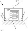
Bei der in
Die Messvorrichtung
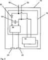
Als Mittel zum Erfassen des jeweiligen Messstroms
Anhand der eine solche Darlington-Schaltung
Die beiden Kontaktflächen
Der jeweilige Messstrom
Indem die Elektronik
Dies ist speziell dann gegeben, wenn von den erfassten Messwerten Behandlungsmaßnahmen abhängen, die von einem jeweiligen Medizingerät
Die Darstellung in
Die Besonderheit einer solchen oder ähnlichen Anordnung und/oder Verteilung der Kontaktflächen
An das Medizingerät
Der Beitrag der Auswerteschaltung
Der von der Messvorrichtung
Bei einer besonderen, nicht gezeigten Ausführungsform der Messvorrichtung
Die Darstellung in
Die in
Einzelne im Vordergrund stehende Aspekte der hier eingereichten Beschreibung lassen sich damit kurz wie folgt zusammenfassen: Angegeben werden eine Messvorrichtung
BezugszeichenlisteLIST OF REFERENCE NUMBERS
- 1010
- Messvorrichtungmeasuring device
- 1212
- Hautoberflächeskin surface
- 1414
- Hautskin
- 1616
- (erster) Sensor(first) sensor
- 1818
- (zweiter) Sensor(second) sensor
- 2020
- (erste) Kontaktfläche(first) contact surface
- 2222
- (zweite) Kontaktfläche(second) contact surface
- 2424
- Unterseite (der Messvorrichtung)Bottom (of the measuring device)
- 2626
- Haftschichtadhesive layer
- 2828
- MedizingerätMedical device
- 3030
- Messstrommeasuring current
- 3232
- Elektronikelectronics
- 3434
- Auswerteschaltungevaluation
- 3636
- Darlington-SchaltungDarlington circuit
- 3838
- Eingang (der Auswerteschaltung)Input (the evaluation circuit)
- 4040
- Eingang (der Auswerteschaltung)Input (the evaluation circuit)
- 4242
- externe Gleichspannungsquelleexternal DC voltage source
- 4444
- Anzeigeeinrichtungdisplay
- 5050
- (erste) Zuleitung (für die Messvorrichtung)(first) supply line (for the measuring device)
- 5252
- (zweite) Zuleitung (für die Messvorrichtung)(second) supply line (for the measuring device)
- 5454
- Speisestromsupply current
- 5656
- Eingangskanal (des Medizingeräts)Input channel (of the medical device)
- 5858
- PolwendeschaltungPolwendeschaltung
- 6060
- Taktgeberclock
- 6262
- Stromsperrelement, insbesondere DiodeCurrent blocking element, in particular diode
- 6464
- lokale Energiequelle, insbesondere Kondensatorlocal energy source, in particular capacitor
ZITATE ENTHALTEN IN DER BESCHREIBUNG QUOTES INCLUDE IN THE DESCRIPTION
Diese Liste der vom Anmelder aufgeführten Dokumente wurde automatisiert erzeugt und ist ausschließlich zur besseren Information des Lesers aufgenommen. Die Liste ist nicht Bestandteil der deutschen Patent- bzw. Gebrauchsmusteranmeldung. Das DPMA übernimmt keinerlei Haftung für etwaige Fehler oder Auslassungen.This list of the documents listed by the applicant has been generated automatically and is included solely for the better information of the reader. The list is not part of the German patent or utility model application. The DPMA assumes no liability for any errors or omissions.
Zitierte PatentliteraturCited patent literature
- DE 2005037921 B3[0002]DE 2005037921 B3[0002]
- DE 102005037921 B3[0003]DE 102005037921 B3[0003]
Zitierte Nicht-PatentliteraturCited non-patent literature
- „Epidermal electronics” von Dae-Hyeong Kim et. al. (Science 12 August 2011: Vol. 333 no. 6244 pp. 840–843[0017]"Epidermal electronics" by Dae-Hyeong Kim et. al. (
Science 12 August 2011: Vol. 333 no. 6244 pp. 840-843[0017]
Claims (12)
Translated fromGermanPriority Applications (5)
| Application Number | Priority Date | Filing Date | Title |
|---|---|---|---|
| DE102013011141.2ADE102013011141A1 (en) | 2013-07-03 | 2013-07-03 | Measuring device for measuring a body function and method for operating such a measuring device |
| PCT/EP2014/001764WO2015000570A1 (en) | 2013-07-03 | 2014-06-27 | Measuring device for measuring body functions |
| CN201480037408.4ACN105874310B (en) | 2013-07-03 | 2014-06-27 | Measure the measuring device of physical function |
| US14/901,821US10376152B2 (en) | 2013-07-03 | 2014-06-27 | Measuring device for measuring a bodily function and method for operating such a measuring device |
| EP14735853.5AEP3017283B1 (en) | 2013-07-03 | 2014-06-27 | Measuring device for measuring body functions |
Applications Claiming Priority (1)
| Application Number | Priority Date | Filing Date | Title |
|---|---|---|---|
| DE102013011141.2ADE102013011141A1 (en) | 2013-07-03 | 2013-07-03 | Measuring device for measuring a body function and method for operating such a measuring device |
Publications (1)
| Publication Number | Publication Date |
|---|---|
| DE102013011141A1true DE102013011141A1 (en) | 2015-01-08 |
Family
ID=51134001
Family Applications (1)
| Application Number | Title | Priority Date | Filing Date |
|---|---|---|---|
| DE102013011141.2AWithdrawnDE102013011141A1 (en) | 2013-07-03 | 2013-07-03 | Measuring device for measuring a body function and method for operating such a measuring device |
Country Status (5)
| Country | Link |
|---|---|
| US (1) | US10376152B2 (en) |
| EP (1) | EP3017283B1 (en) |
| CN (1) | CN105874310B (en) |
| DE (1) | DE102013011141A1 (en) |
| WO (1) | WO2015000570A1 (en) |
Families Citing this family (5)
| Publication number | Priority date | Publication date | Assignee | Title |
|---|---|---|---|---|
| US10141492B2 (en) | 2015-05-14 | 2018-11-27 | Nimbus Materials Inc. | Energy harvesting for wearable technology through a thin flexible thermoelectric device |
| WO2019225532A1 (en) | 2018-05-21 | 2019-11-28 | 株式会社村田製作所 | Paste-type deep body thermometer |
| KR20210120174A (en) | 2020-03-25 | 2021-10-07 | 삼성전자주식회사 | Apparatus and method for analyzing composition in body, and impedance measuring apparatus |
| US20210345887A1 (en)* | 2020-05-11 | 2021-11-11 | Dermal Photonics Corporation | Wearable thermometer device |
| US20230172456A1 (en)* | 2020-05-28 | 2023-06-08 | Nippon Telegraph And Telephone Corporation | Installation State Determination Method, and Installation State Determination System |
Citations (7)
| Publication number | Priority date | Publication date | Assignee | Title |
|---|---|---|---|---|
| DE69604767T2 (en)* | 1995-12-07 | 2000-02-03 | Datex-Ohmeda, Inc. | Method of tracking probe removal |
| DE10005526A1 (en)* | 2000-02-08 | 2001-08-30 | Klaschka Gmbh & Co | Device for monitoring the physiological functioning of a patient or animal in which physiological sensors are linked to a processor that transmits medical data via a mobile phone, enabling a patient to be more mobile |
| DE69431281T2 (en)* | 1993-06-04 | 2003-05-22 | Pacesetter, Inc. | HEART PACER WITH ELECTRODE AND INTEGRATED OXYGEN SENSOR |
| US20050085751A1 (en)* | 2003-09-10 | 2005-04-21 | Shalom Daskal | Disposable electric bandage |
| DE102004031672A1 (en)* | 2004-06-30 | 2006-01-19 | Infineon Technologies Ag | Planar sensor array, sensor array, and method of fabricating a planar sensor array |
| DE102005037921B3 (en) | 2005-08-11 | 2006-06-14 | Dräger Medical AG & Co. KG | Temperature measuring device, for patient use, has evaluating means for detecting skin surface temperature from first temperature measured value and determines temperature at skin surface where double temperature sensor is in contact |
| US20090163787A1 (en)* | 2007-12-21 | 2009-06-25 | Nellcor Puritan Bennett Llc | Medical sensor and technique for using the same |
Family Cites Families (77)
| Publication number | Priority date | Publication date | Assignee | Title |
|---|---|---|---|---|
| US4331161A (en)* | 1979-05-17 | 1982-05-25 | Healthdyne, Inc. | Patient sensor continuity detector |
| US4295475A (en) | 1979-10-26 | 1981-10-20 | Air Shields, Inc. | Probe and system for detecting probe dislodgement |
| US4830014A (en)* | 1983-05-11 | 1989-05-16 | Nellcor Incorporated | Sensor having cutaneous conformance |
| JP2545740B2 (en)* | 1994-03-18 | 1996-10-23 | 工業技術院長 | Temperature sensor |
| JPH09215755A (en)* | 1996-02-09 | 1997-08-19 | Poritoronikusu:Kk | Skin contact treating implement |
| US5913830A (en)* | 1997-08-20 | 1999-06-22 | Respironics, Inc. | Respiratory inductive plethysmography sensor |
| JPH11176491A (en)* | 1997-10-07 | 1999-07-02 | Seiko Instruments Inc | Electronic device charging system |
| US6526300B1 (en) | 1999-06-18 | 2003-02-25 | Masimo Corporation | Pulse oximeter probe-off detection system |
| WO2001063738A2 (en)* | 2000-02-23 | 2001-08-30 | Sri International | Electroactive polymer thermal electric generators |
| WO2001088534A2 (en)* | 2000-05-16 | 2001-11-22 | Cygnus, Inc. | Methods for improving performance and reliability of biosensors |
| US6602201B1 (en)* | 2000-07-10 | 2003-08-05 | Cardiodynamics International Corporation | Apparatus and method for determining cardiac output in a living subject |
| US8328420B2 (en)* | 2003-04-22 | 2012-12-11 | Marcio Marc Abreu | Apparatus and method for measuring biologic parameters |
| US8849379B2 (en)* | 2002-04-22 | 2014-09-30 | Geelux Holdings, Ltd. | Apparatus and method for measuring biologic parameters |
| KR100459903B1 (en)* | 2002-07-25 | 2004-12-03 | 삼성전자주식회사 | Measurement system and electrode for measuring the impedance of small area of skin |
| GB0228375D0 (en)* | 2002-12-05 | 2003-01-08 | Innovation And Entpr Off Of | Wound mapping |
| US7289927B2 (en)* | 2004-07-23 | 2007-10-30 | Cybiocare, Inc. | Method and apparatus for the monitoring of body temperature and/or blood flow |
| WO2006026748A1 (en)* | 2004-08-31 | 2006-03-09 | Lifescan Scotland Limited | Method of manufacturing an auto-calibrating sensor |
| ITMI20051129A1 (en)* | 2005-06-15 | 2006-12-16 | Cometa S A S | PERFORMED ELECTROMYOGRAPH FOR THE DETECTION OF ELECTROMYOGRAPHY SIGNALS ON MOVING PERSONS. |
| US7733224B2 (en)* | 2006-06-30 | 2010-06-08 | Bao Tran | Mesh network personal emergency response appliance |
| EP1963832A2 (en)* | 2005-12-16 | 2008-09-03 | Bayer Healthcare, LLC | Dual transdermal analyte sensor assembly and methods of using the same |
| CA2538940A1 (en)* | 2006-03-03 | 2006-06-22 | James W. Haslett | Bandage with sensors |
| US7813444B2 (en)* | 2006-04-11 | 2010-10-12 | Nokia Corporation | Measurement method and arrangement for amplitude and phase synchronization in a polar transmitter |
| US7522061B2 (en)* | 2006-04-28 | 2009-04-21 | Medtronic, Inc. | External voiding sensor system |
| US7626114B2 (en)* | 2006-06-16 | 2009-12-01 | Digital Angel Corporation | Thermoelectric power supply |
| US20090015413A1 (en)* | 2006-07-21 | 2009-01-15 | Texas Instruments Incorporated | Wirelessly transmitting biological parameters |
| GB0614777D0 (en)* | 2006-07-25 | 2006-09-06 | Gilbe Ivor S | Method of charging implanted devices by direct transfer of electrical energy |
| US9389260B2 (en)* | 2012-09-28 | 2016-07-12 | General Electric Company | Systems and methods for monitoring sensors |
| US9147144B2 (en)* | 2012-09-28 | 2015-09-29 | General Electric Company | Systems and methods for monitoring sensors |
| US8157730B2 (en)* | 2006-12-19 | 2012-04-17 | Valencell, Inc. | Physiological and environmental monitoring systems and methods |
| US7705725B2 (en)* | 2007-01-08 | 2010-04-27 | The Boeing Company | Methods and systems for monitoring structures and systems |
| RU2466676C2 (en)* | 2007-03-15 | 2012-11-20 | Конинклейке Филипс Электроникс Н.В. | Methods and devices for core temperature measurement |
| US8115448B2 (en)* | 2007-06-01 | 2012-02-14 | Michael Sasha John | Systems and methods for wireless power |
| US8994528B2 (en)* | 2007-06-15 | 2015-03-31 | Board Of Regents, The University Of Texas System | Thin flexible sensor |
| WO2009036369A1 (en)* | 2007-09-14 | 2009-03-19 | Corventis, Inc. | System and methods for wireless body fluid monitoring |
| EP2194858B1 (en)* | 2007-09-14 | 2017-11-22 | Corventis, Inc. | Medical device automatic start-up upon contact to patient tissue |
| US20090287076A1 (en)* | 2007-12-18 | 2009-11-19 | Boyden Edward S | System, devices, and methods for detecting occlusions in a biological subject |
| US9672471B2 (en)* | 2007-12-18 | 2017-06-06 | Gearbox Llc | Systems, devices, and methods for detecting occlusions in a biological subject including spectral learning |
| US20100253525A1 (en)* | 2007-12-20 | 2010-10-07 | Honeywell International Inc. | Systems and methods for human performance augmentation |
| EP2099079A1 (en)* | 2008-03-05 | 2009-09-09 | Stichting IMEC Nederland | Hybrid energy scavenger comprising thermopile unit and photovoltaic cells |
| WO2009146214A1 (en)* | 2008-04-18 | 2009-12-03 | Corventis, Inc. | Method and apparatus to measure bioelectric impedance of patient tissue |
| US8700118B2 (en)* | 2008-05-01 | 2014-04-15 | 3M Innovative Properties Company | Biomedical sensor system |
| US8381601B2 (en)* | 2008-05-05 | 2013-02-26 | John F. Stumpf | Transducer matrix film |
| EP2296542A4 (en)* | 2008-05-16 | 2013-06-05 | Heartscape Technologies Inc | Electrode patch monitoring device |
| US8075181B1 (en)* | 2008-05-29 | 2011-12-13 | The Regents Of The University Of California | Thermal monitoring device |
| US20100081892A1 (en)* | 2008-09-30 | 2010-04-01 | NelIcor Puritan Bennett Ireland | Systems and Methods for Combined Pulse Oximetry and Blood Pressure Measurement |
| US20120245439A1 (en)* | 2008-11-20 | 2012-09-27 | David Andre | Method and apparatus for determining critical care parameters |
| FR2940904B1 (en)* | 2009-01-13 | 2012-08-31 | Urgo Laboratoires | INTERFACE PRESSURE MEASURING SYSTEM |
| JP5628289B2 (en)* | 2009-04-17 | 2014-11-19 | バイオボーション・アーゲーBiovotion AG | Broadband field response measurement for glucose determination |
| US9826905B2 (en)* | 2009-05-07 | 2017-11-28 | Nellcor Puritan Bennett Ireland | Using colored probes in patient monitoring |
| EP2251660B1 (en)* | 2009-05-14 | 2016-07-27 | Drägerwerk AG & Co. KGaA | Double temperature sensor |
| JP5358332B2 (en)* | 2009-07-23 | 2013-12-04 | テルモ株式会社 | Body temperature measurement system, data reader, and drive control method thereof |
| US8325048B2 (en)* | 2009-12-08 | 2012-12-04 | Kimberly-Clark Worldwide, Inc. | Thermal stress indicator |
| JP5648283B2 (en)* | 2009-12-24 | 2015-01-07 | セイコーエプソン株式会社 | Electronic thermometer and body temperature measuring method |
| US8428676B2 (en)* | 2010-03-31 | 2013-04-23 | Covidien Lp | Thermoelectric energy harvesting with wireless sensors |
| EP2433675B1 (en)* | 2010-09-24 | 2013-01-09 | Sorin CRM SAS | Active implantable medical device including a means for wireless communication via electric pulses conducted by the interstitial tissue of the body |
| JP5578028B2 (en)* | 2010-10-29 | 2014-08-27 | セイコーエプソン株式会社 | Temperature measuring apparatus and temperature measuring method |
| WO2012067115A1 (en)* | 2010-11-16 | 2012-05-24 | テルモ株式会社 | Sensor system, and method for using sensor system |
| US20120152297A1 (en)* | 2010-12-15 | 2012-06-21 | The Boeing Company | Power generation using a thermoelectric generator and a phase change material |
| US20120271121A1 (en)* | 2010-12-29 | 2012-10-25 | Basis Science, Inc. | Integrated Biometric Sensing and Display Device |
| US20120326863A1 (en)* | 2011-06-27 | 2012-12-27 | General Electric Company | Wearable portable device and method |
| US20130087180A1 (en)* | 2011-10-10 | 2013-04-11 | Perpetua Power Source Technologies, Inc. | Wearable thermoelectric generator system |
| US9766053B1 (en)* | 2011-11-21 | 2017-09-19 | The United States Of America As Represented By The Administrator Of Nasa | Material damage system and method for determining same |
| US8834389B2 (en)* | 2011-11-25 | 2014-09-16 | Tepsync | Temperature based fertility monitoring system and related method |
| US10342446B2 (en)* | 2011-11-30 | 2019-07-09 | Welch Allyn, Inc. | Thermal powered medical device |
| US9700222B2 (en)* | 2011-12-02 | 2017-07-11 | Lumiradx Uk Ltd | Health-monitor patch |
| KR101312553B1 (en)* | 2011-12-28 | 2013-10-14 | 한국표준과학연구원 | Attaching structure of a tactile sensor to a curved surface and method of attaching a tactile sensor to a curved surface |
| US20130201316A1 (en)* | 2012-01-09 | 2013-08-08 | May Patents Ltd. | System and method for server based control |
| EP2833785A4 (en)* | 2012-04-03 | 2015-10-28 | Altec Inc | Disposable low-profile conformable biomedical sensor |
| US9183738B1 (en)* | 2012-04-19 | 2015-11-10 | iDevices, LLC | Wireless thermometer and method of use thereof |
| JP6243136B2 (en)* | 2012-05-02 | 2017-12-06 | 株式会社半導体エネルギー研究所 | Switching converter |
| US9820692B2 (en)* | 2012-05-10 | 2017-11-21 | The Regents Of The University Of California | Wearable electrochemical sensors |
| US9254099B2 (en)* | 2013-05-23 | 2016-02-09 | Medibotics Llc | Smart watch and food-imaging member for monitoring food consumption |
| US10413251B2 (en)* | 2012-10-07 | 2019-09-17 | Rhythm Diagnostic Systems, Inc. | Wearable cardiac monitor |
| US20140200486A1 (en)* | 2013-01-17 | 2014-07-17 | Quaerimus, Inc. | System and method for continuous monitoring of a human foot for signs of ulcer development |
| US10141492B2 (en)* | 2015-05-14 | 2018-11-27 | Nimbus Materials Inc. | Energy harvesting for wearable technology through a thin flexible thermoelectric device |
| NL2013884B1 (en)* | 2014-11-27 | 2016-10-11 | Umc Utrecht Holding Bv | Wearable ultrasound device for signalling changes in human or animal body. |
| US9891252B2 (en)* | 2015-07-28 | 2018-02-13 | Panoramic Power Ltd. | Thermal management of self-powered power sensors |
- 2013
- 2013-07-03DEDE102013011141.2Apatent/DE102013011141A1/ennot_activeWithdrawn
- 2014
- 2014-06-27CNCN201480037408.4Apatent/CN105874310B/ennot_activeExpired - Fee Related
- 2014-06-27EPEP14735853.5Apatent/EP3017283B1/ennot_activeNot-in-force
- 2014-06-27WOPCT/EP2014/001764patent/WO2015000570A1/enactiveApplication Filing
- 2014-06-27USUS14/901,821patent/US10376152B2/enactiveActive
Patent Citations (7)
| Publication number | Priority date | Publication date | Assignee | Title |
|---|---|---|---|---|
| DE69431281T2 (en)* | 1993-06-04 | 2003-05-22 | Pacesetter, Inc. | HEART PACER WITH ELECTRODE AND INTEGRATED OXYGEN SENSOR |
| DE69604767T2 (en)* | 1995-12-07 | 2000-02-03 | Datex-Ohmeda, Inc. | Method of tracking probe removal |
| DE10005526A1 (en)* | 2000-02-08 | 2001-08-30 | Klaschka Gmbh & Co | Device for monitoring the physiological functioning of a patient or animal in which physiological sensors are linked to a processor that transmits medical data via a mobile phone, enabling a patient to be more mobile |
| US20050085751A1 (en)* | 2003-09-10 | 2005-04-21 | Shalom Daskal | Disposable electric bandage |
| DE102004031672A1 (en)* | 2004-06-30 | 2006-01-19 | Infineon Technologies Ag | Planar sensor array, sensor array, and method of fabricating a planar sensor array |
| DE102005037921B3 (en) | 2005-08-11 | 2006-06-14 | Dräger Medical AG & Co. KG | Temperature measuring device, for patient use, has evaluating means for detecting skin surface temperature from first temperature measured value and determines temperature at skin surface where double temperature sensor is in contact |
| US20090163787A1 (en)* | 2007-12-21 | 2009-06-25 | Nellcor Puritan Bennett Llc | Medical sensor and technique for using the same |
Non-Patent Citations (2)
| Title |
|---|
| "Epidermal electronics" von Dae-Hyeong Kim et. al. (Science 12 August 2011: Vol. 333 no. 6244 pp. 840-843 |
| KIM, Dae-Hyeong [et al.]: Epidermal Electronics. In: Science Vol. 333, 12. August 2011, S. 838-843* |
Also Published As
| Publication number | Publication date |
|---|---|
| US10376152B2 (en) | 2019-08-13 |
| WO2015000570A1 (en) | 2015-01-08 |
| EP3017283A1 (en) | 2016-05-11 |
| EP3017283B1 (en) | 2017-10-25 |
| US20160367150A1 (en) | 2016-12-22 |
| CN105874310B (en) | 2019-11-05 |
| CN105874310A (en) | 2016-08-17 |
Similar Documents
| Publication | Publication Date | Title |
|---|---|---|
| EP3017283B1 (en) | Measuring device for measuring body functions | |
| DE60022515T2 (en) | DEVICE FOR RECEIVING HARM INCONTINENCE OF A PATIENT | |
| DE102009053113B4 (en) | Serial interlock system with built-in ability to identify broken points and implementation procedures | |
| DE102015212800A1 (en) | Device for measuring the temperature of electrochemical cells in a battery pack | |
| DE102010007784A1 (en) | Device for electrical circuit monitoring | |
| DE112013005610T5 (en) | Capacitive occupancy or proximity detector | |
| DE102011083307A1 (en) | Device for measuring a battery current | |
| EP3887835B1 (en) | Device and method for automatic testing of a switching body | |
| DE102011009263A1 (en) | Child seat status query and power supply | |
| DE102011111266A1 (en) | Child seat status query and power supply | |
| DE102009028941A1 (en) | battery Pack | |
| DE102014224171B4 (en) | Arrangement with a collision detection device, medical imaging device with a collision detection device and method for operating a collision detection device | |
| DE3018863A1 (en) | HEATED MEASURING METER FOR PHYSIOLOGICAL MEASUREMENTS WITH A BUILT-IN TEMPERATURE-CONTROLLED SWITCH | |
| EP2853195B1 (en) | Seat or couch in a vehicle with a sensor for non-contact electrocardiographic measurement | |
| DE102014219807B4 (en) | Method and device for testing the functionality of a current sensor and vehicle | |
| DE102015217723A1 (en) | Local transmitter coil with integrated safety device | |
| DE102008011142A1 (en) | Monitoring system for monitoring occupancy of bed in e.g. hospital, for comatose patient, has sensor device designed such that relative movement between vertical spring-loaded cross member/crossbar and frame of bed base is detected | |
| DE102015015350A1 (en) | Magnetic field detector circuit and method of operating a magnetic field detector circuit | |
| DE112021000192T5 (en) | MEASURING DEVICE FOR BIOLOGICAL INFORMATION | |
| EP1973014B1 (en) | Device and method for automatic recognition and differentiation of one or two channel electronic sensors connected to a two channel safety combination | |
| DE2128726A1 (en) | Electronic alarm indicator | |
| DE102015005963A1 (en) | State recognition of a central locking via current detection | |
| DE102013219514A1 (en) | Sensor for contactless electrocardiographic measurement, sensor array and seat or couch | |
| DE102014206360A1 (en) | Method for testing a self-holding magnet of a switch and test device for the self-holding magnet | |
| DE102022200345A1 (en) | battery |
Legal Events
| Date | Code | Title | Description |
|---|---|---|---|
| R012 | Request for examination validly filed | ||
| R016 | Response to examination communication | ||
| R081 | Change of applicant/patentee | Owner name:DRAEGERWERK AG & CO. KGAA, DE Free format text:FORMER OWNER: DRAEGER MEDICAL GMBH, 23558 LUEBECK, DE | |
| R119 | Application deemed withdrawn, or ip right lapsed, due to non-payment of renewal fee |