DE102013003841B4 - vibration - Google Patents
vibrationDownload PDFInfo
- Publication number
- DE102013003841B4 DE102013003841B4DE102013003841.3ADE102013003841ADE102013003841B4DE 102013003841 B4DE102013003841 B4DE 102013003841B4DE 102013003841 ADE102013003841 ADE 102013003841ADE 102013003841 B4DE102013003841 B4DE 102013003841B4
- Authority
- DE
- Germany
- Prior art keywords
- chamber
- valve
- tube
- vibration damper
- electrode tube
- Prior art date
- Legal status (The legal status is an assumption and is not a legal conclusion. Google has not performed a legal analysis and makes no representation as to the accuracy of the status listed.)
- Expired - Fee Related
Links
- 239000012530fluidSubstances0.000claimsabstractdescription23
- 238000013016dampingMethods0.000claimsabstractdescription12
- 239000000565sealantSubstances0.000claimsabstractdescription4
- 238000007789sealingMethods0.000claimsdescription13
- 229920001971elastomerPolymers0.000claimsdescription4
- 239000000463materialSubstances0.000claimsdescription3
- 239000011248coating agentSubstances0.000claimsdescription2
- 238000000576coating methodMethods0.000claimsdescription2
- 239000000806elastomerSubstances0.000claimsdescription2
- 230000005684electric fieldEffects0.000claimsdescription2
- 229910052751metalInorganic materials0.000claimsdescription2
- 239000002184metalSubstances0.000claimsdescription2
- 239000004033plasticSubstances0.000claimsdescription2
- 230000000630rising effectEffects0.000claimsdescription2
- 239000004922lacquerSubstances0.000claims1
- 239000006096absorbing agentSubstances0.000description4
- 230000035939shockEffects0.000description4
- 230000002238attenuated effectEffects0.000description2
- 230000006835compressionEffects0.000description2
- 238000007906compressionMethods0.000description2
- 230000001419dependent effectEffects0.000description2
- 238000009434installationMethods0.000description2
- 239000002966varnishSubstances0.000description2
- 229910001369BrassInorganic materials0.000description1
- 230000002411adverseEffects0.000description1
- 229910052782aluminiumInorganic materials0.000description1
- XAGFODPZIPBFFR-UHFFFAOYSA-NaluminiumChemical compound[Al]XAGFODPZIPBFFR-UHFFFAOYSA-N0.000description1
- 230000015572biosynthetic processEffects0.000description1
- 239000010951brassSubstances0.000description1
- 239000003795chemical substances by applicationSubstances0.000description1
- 238000011161developmentMethods0.000description1
- 230000018109developmental processEffects0.000description1
- 230000000694effectsEffects0.000description1
- 238000010292electrical insulationMethods0.000description1
- 238000009413insulationMethods0.000description1
- 230000007774longtermEffects0.000description1
- 230000000149penetrating effectEffects0.000description1
- 230000005855radiationEffects0.000description1
Images


Classifications
- B—PERFORMING OPERATIONS; TRANSPORTING
- B60—VEHICLES IN GENERAL
- B60G—VEHICLE SUSPENSION ARRANGEMENTS
- B60G13/00—Resilient suspensions characterised by arrangement, location or type of vibration dampers
- B60G13/02—Resilient suspensions characterised by arrangement, location or type of vibration dampers having dampers dissipating energy, e.g. frictionally
- B60G13/06—Resilient suspensions characterised by arrangement, location or type of vibration dampers having dampers dissipating energy, e.g. frictionally of fluid type
- B60G13/08—Resilient suspensions characterised by arrangement, location or type of vibration dampers having dampers dissipating energy, e.g. frictionally of fluid type hydraulic
- F—MECHANICAL ENGINEERING; LIGHTING; HEATING; WEAPONS; BLASTING
- F16—ENGINEERING ELEMENTS AND UNITS; GENERAL MEASURES FOR PRODUCING AND MAINTAINING EFFECTIVE FUNCTIONING OF MACHINES OR INSTALLATIONS; THERMAL INSULATION IN GENERAL
- F16F—SPRINGS; SHOCK-ABSORBERS; MEANS FOR DAMPING VIBRATION
- F16F9/00—Springs, vibration-dampers, shock-absorbers, or similarly-constructed movement-dampers using a fluid or the equivalent as damping medium
- F16F9/06—Springs, vibration-dampers, shock-absorbers, or similarly-constructed movement-dampers using a fluid or the equivalent as damping medium using both gas and liquid
- F16F9/062—Bi-tubular units
- F—MECHANICAL ENGINEERING; LIGHTING; HEATING; WEAPONS; BLASTING
- F16—ENGINEERING ELEMENTS AND UNITS; GENERAL MEASURES FOR PRODUCING AND MAINTAINING EFFECTIVE FUNCTIONING OF MACHINES OR INSTALLATIONS; THERMAL INSULATION IN GENERAL
- F16F—SPRINGS; SHOCK-ABSORBERS; MEANS FOR DAMPING VIBRATION
- F16F9/00—Springs, vibration-dampers, shock-absorbers, or similarly-constructed movement-dampers using a fluid or the equivalent as damping medium
- F16F9/32—Details
- F16F9/34—Special valve constructions; Shape or construction of throttling passages
- F16F9/346—Throttling passages in the form of slots arranged in cylinder walls
- F—MECHANICAL ENGINEERING; LIGHTING; HEATING; WEAPONS; BLASTING
- F16—ENGINEERING ELEMENTS AND UNITS; GENERAL MEASURES FOR PRODUCING AND MAINTAINING EFFECTIVE FUNCTIONING OF MACHINES OR INSTALLATIONS; THERMAL INSULATION IN GENERAL
- F16F—SPRINGS; SHOCK-ABSORBERS; MEANS FOR DAMPING VIBRATION
- F16F9/00—Springs, vibration-dampers, shock-absorbers, or similarly-constructed movement-dampers using a fluid or the equivalent as damping medium
- F16F9/32—Details
- F16F9/53—Means for adjusting damping characteristics by varying fluid viscosity, e.g. electromagnetically
- F16F9/532—Electrorheological [ER] fluid dampers
- B—PERFORMING OPERATIONS; TRANSPORTING
- B60—VEHICLES IN GENERAL
- B60G—VEHICLE SUSPENSION ARRANGEMENTS
- B60G2202/00—Indexing codes relating to the type of spring, damper or actuator
- B60G2202/20—Type of damper
- B60G2202/24—Fluid damper
- B—PERFORMING OPERATIONS; TRANSPORTING
- B60—VEHICLES IN GENERAL
- B60G—VEHICLE SUSPENSION ARRANGEMENTS
- B60G2500/00—Indexing codes relating to the regulated action or device
- B60G2500/10—Damping action or damper
- F—MECHANICAL ENGINEERING; LIGHTING; HEATING; WEAPONS; BLASTING
- F16—ENGINEERING ELEMENTS AND UNITS; GENERAL MEASURES FOR PRODUCING AND MAINTAINING EFFECTIVE FUNCTIONING OF MACHINES OR INSTALLATIONS; THERMAL INSULATION IN GENERAL
- F16F—SPRINGS; SHOCK-ABSORBERS; MEANS FOR DAMPING VIBRATION
- F16F2224/00—Materials; Material properties
- F16F2224/04—Fluids
- F16F2224/043—Fluids electrorheological
- F—MECHANICAL ENGINEERING; LIGHTING; HEATING; WEAPONS; BLASTING
- F16—ENGINEERING ELEMENTS AND UNITS; GENERAL MEASURES FOR PRODUCING AND MAINTAINING EFFECTIVE FUNCTIONING OF MACHINES OR INSTALLATIONS; THERMAL INSULATION IN GENERAL
- F16F—SPRINGS; SHOCK-ABSORBERS; MEANS FOR DAMPING VIBRATION
- F16F2230/00—Purpose; Design features
- F16F2230/24—Detecting or preventing malfunction, e.g. fail safe
- F—MECHANICAL ENGINEERING; LIGHTING; HEATING; WEAPONS; BLASTING
- F16—ENGINEERING ELEMENTS AND UNITS; GENERAL MEASURES FOR PRODUCING AND MAINTAINING EFFECTIVE FUNCTIONING OF MACHINES OR INSTALLATIONS; THERMAL INSULATION IN GENERAL
- F16F—SPRINGS; SHOCK-ABSORBERS; MEANS FOR DAMPING VIBRATION
- F16F9/00—Springs, vibration-dampers, shock-absorbers, or similarly-constructed movement-dampers using a fluid or the equivalent as damping medium
- F16F9/06—Springs, vibration-dampers, shock-absorbers, or similarly-constructed movement-dampers using a fluid or the equivalent as damping medium using both gas and liquid
- F—MECHANICAL ENGINEERING; LIGHTING; HEATING; WEAPONS; BLASTING
- F16—ENGINEERING ELEMENTS AND UNITS; GENERAL MEASURES FOR PRODUCING AND MAINTAINING EFFECTIVE FUNCTIONING OF MACHINES OR INSTALLATIONS; THERMAL INSULATION IN GENERAL
- F16F—SPRINGS; SHOCK-ABSORBERS; MEANS FOR DAMPING VIBRATION
- F16F9/00—Springs, vibration-dampers, shock-absorbers, or similarly-constructed movement-dampers using a fluid or the equivalent as damping medium
- F16F9/10—Springs, vibration-dampers, shock-absorbers, or similarly-constructed movement-dampers using a fluid or the equivalent as damping medium using liquid only; using a fluid of which the nature is immaterial
- F16F9/14—Devices with one or more members, e.g. pistons, vanes, moving to and fro in chambers and using throttling effect
- F16F9/16—Devices with one or more members, e.g. pistons, vanes, moving to and fro in chambers and using throttling effect involving only straight-line movement of the effective parts
- F16F9/18—Devices with one or more members, e.g. pistons, vanes, moving to and fro in chambers and using throttling effect involving only straight-line movement of the effective parts with a closed cylinder and a piston separating two or more working spaces therein
- F16F9/185—Bitubular units
Landscapes
- Engineering & Computer Science (AREA)
- General Engineering & Computer Science (AREA)
- Mechanical Engineering (AREA)
- Physics & Mathematics (AREA)
- Electromagnetism (AREA)
- Fluid-Damping Devices (AREA)
- Vehicle Body Suspensions (AREA)
Abstract
Translated fromGermanDescription
Translated fromGermanDie Erfindung betrifft einen Schwingungsdämpfer zur Dämpfung von Ein- und Ausfederkräften an Kraftfahrzeugen gemäß dem Oberbegriff des Patentanspruchs 1.The invention relates to a vibration damper for damping of compression and rebound forces on motor vehicles according to the preamble of
Schwingungsdämpfer dienen in Kraftfahrzeugen dazu, dass die Schwingungen des Fahrwerks als gefederte Massen schnell abklingen, um die Fahrstabilität sicherzustellen und einen gewünschten Fahrkomfort zu schaffen. Dazu werden meist hydraulische Schwingungsdämpfer eingesetzt, bei denen in einem mit Öl befüllten Zylinder ein axial verschiebbarer Kolben geführt ist. Am Kolben ist eine Kolbenstange angeordnet, die nach oben aus dem Zylinder abgedichtet herausgeführt ist und am Fahrzeugchassis befestigt wird. Andererseits ist der Zylinder mit seinem unteren Ende vorzugsweise an einem Rad- oder Achsteil angebracht. Der Kolben unterteilt dabei den Zylinder in eine obere Ausfahrkammer und eine untere Einfahrkammer, die über mindestens ein Drosselventil miteinander verbunden sind. Zum Ausgleich einer einsinkenden Kolbenstange ist die Einfahrkammer zusätzlich noch mit einer Gasdruckkammer verbunden, in der ein Vordruck von ca. 20 bis 30 bar eingegeben ist, um eine Kavitation zu vermeiden. Zur Regelung oder Steuerung der Dämpferkräfte können die Drosselventile elektromagnetisch verstellbar ausgebildet sein, um das Fahrverhalten eines Fahrzeugs an eine vorgegebene Schwingungsdämpfung und/oder einen gewünschten Fahrkomfort anpassen zu können. Allerdings sind derartige Drosselventile relativ langsam in ihrem Regelverhalten, so dass häufig schnelle Schwingungsänderungen nicht schnell genug gedämpft werden können.Vibration dampers are used in motor vehicles to ensure that the vibrations of the chassis as sprung masses decay quickly to ensure the driving stability and to create a desired ride comfort. For this purpose, hydraulic vibration dampers are usually used, in which an axially displaceable piston is guided in a cylinder filled with oil. On the piston, a piston rod is arranged, which is brought out of the cylinder sealed upwards and secured to the vehicle chassis. On the other hand, the cylinder is preferably attached with its lower end to a wheel or axle part. The piston divides the cylinder into an upper Ausfahrkammer and a lower retraction chamber, which are interconnected via at least one throttle valve. To compensate for a sinking piston rod, the retraction chamber is additionally connected to a gas pressure chamber in which a pre-pressure of about 20 to 30 bar is entered in order to avoid cavitation. For controlling or controlling the damping forces, the throttle valves may be designed to be electromagnetically adjustable in order to be able to adapt the driving behavior of a vehicle to a predetermined vibration damping and / or a desired driving comfort. However, such throttle valves are relatively slow in their control behavior, so that often fast vibration changes can not be damped quickly enough.
Aus der
Ein weiterer elektrorheologischer Schwingungsdämpfer ist aus der
Desweiteren bewirkt der Zweirohrdämpfer auch durch die drei radial nebeneinander angeordneten Drosselspalte einen verhältnismäßig großen Außendurchmesser, so dass ein derartiger Einbauraum z. B. innerhalb von Schraubenfedern häufig nicht zur Verfügung steht.Furthermore, the two-tube damper causes by the three radially juxtaposed throttle gaps a relatively large outer diameter, so that such an installation space z. B. is often not available within coil springs.
Aus der
Der Erfindung liegt deshalb die Aufgabe zugrunde, einen Schwingungsdämpfer der eingangs genannten Art so zu verbessern, dass er mit kompakten Außenabmessungen ausführbar ist und eine gleichbleibend gute und schnelle Schwingungsdämpfung bewirkt.The invention is therefore based on the object to improve a vibration damper of the type mentioned so that it can be executed with compact outer dimensions and causes a consistently good and fast vibration damping.
Diese Aufgabe wird durch die im Patentanspruch 1 angegebene Erfindung gelöst. Weiterbildungen und vorteilhafte Ausführungsbeispiele der Erfindung sind in den Unteransprüchen angegeben.This object is achieved by the invention defined in
Die Erfindung hat den Vorteil, dass durch das Rückschlagventil zwischen der Ausfahrkammer und der Gasdruckkammer ein in die Ausfahrkammer oder die Drosselspalte eingedrungenes gasförmiges Druckmittel schnell wieder zur Gasdruckkammer zurückgeleitet wird, wodurch die gewünschte Schwingungsdämpfung mittels der elektrorheologischen Flüssigkeit langfristig erhalten bleibt. Gleichzeitig wird dadurch die Gefahr vermindert, dass durch ein gasförmiges Druckmittel in den Ventilspalten es zu Spannungsüberschlägen zwischen den Elektrodenpolen kommt.The invention has the advantage that by the check valve between the extension chamber and the gas pressure chamber in the Ausfahrkammer or the throttle gaps penetrated gaseous pressure medium quickly back to Gas pressure chamber is returned, whereby the desired vibration damping by means of the electrorheological fluid is maintained long term. At the same time, this reduces the risk of voltage flashovers between the electrode poles due to a gaseous pressure medium in the valve gaps.
Die Erfindung hat weiterhin den Vorteil, dass durch die Bildung von Ventilteilspalten zwischen dem Zylinderinnenrohr und dem Elektrodenrohr mittels Dichtmitteln eine Zentrierung der Rohre erreicht wird, wodurch sich auch die Genauigkeit der Spalthöhen verbessern lässt. Dadurch erhöht sich gleichzeitig die Genauigkeit der Schwingungsdämpfung, da bei gleichbleibender Spalthöhe eine gleichbleibende Viskosität über die gesamte Spaltlänge steuerbar ist. Dies wird insbesondere durch die schraubenwendelförmigen Dichtmittel als Doppelhelix erreicht, weil diese die Spaltlängen erhöhen, die zur Viskositätssteuerung zur Verfügung steht.The invention also has the advantage that centering of the tubes is achieved by the formation of partial valve gaps between the cylinder inner tube and the electrode tube by means of sealing means, whereby the accuracy of the gap heights can also be improved. This simultaneously increases the accuracy of the vibration damping, since at the same gap height a constant viscosity over the entire gap length is controllable. This is achieved in particular by the helical sealants as a double helix because they increase the gap lengths available for viscosity control.
Desweiteren wird durch den kraftschlüssigen Einsatz der Dichtmittel zwischen dem Zylinderinnenrohr und dem Elektrodenrohr eine höhere mechanische Steifigkeit des Schwingungsdämpfers bei geringen Wanddicken der einzelnen Rohre erreicht.Furthermore, a higher mechanical rigidity of the vibration damper is achieved with small wall thicknesses of the individual tubes by the non-positive use of the sealing means between the cylinder inner tube and the electrode tube.
Bei einer besonderen Ausbildung der Erfindung ist zusätzlich vorgesehen, dass Elektrodenrohr auf seiner äußeren Mantelfläche mit einer elektrischen Isolationsschicht oder einem Isolationslack zu versehen, was den Vorteil hat, dass dadurch nur eine verhältnismäßig geringe Steuerenergie notwendig ist, weil kaum Steuerenergie nach außen abgestrahlt wird.In a particular embodiment of the invention, it is additionally provided that the electrode tube is provided on its outer lateral surface with an electrical insulation layer or an insulating varnish, which has the advantage that only a relatively small control energy is necessary because hardly any control energy is emitted to the outside.
Bei einer weiteren besonderen Ausbildung der Erfindung ist am Schwingungsdämpfer eine elektronische Steuerschaltung als Hochvoltelektronik vorgesehen, die aufgrund der Standzeit und des zuletzt zurückgelegten Dämpferwegs den für die vorgegebenen Dämpfung notwendigen Steuerspannungswert errechnet, wodurch der Vorteil entsteht, dass dadurch der Stromanstieg begrenzbar und gleichzeitig ein Spannungsüberschlag vermindert und ein übermäßiger Temperaturanstieg im Drosselspalt vermieden wird.In a further particular embodiment of the invention, an electronic control circuit is provided as high-voltage electronics, which calculates the necessary for the given attenuation control voltage value due to the life and the last muted damper, creating the advantage that thereby the current increase limited and simultaneously reduces a voltage flashover and excessive temperature rise in the throttle gap is avoided.
Die Erfindung wird anhand eines Ausführungsbeispiels, das in der Zeichnung dargestellt ist, näher erläutert. Es zeigen:The invention will be explained in more detail with reference to an embodiment which is illustrated in the drawing. Show it:
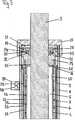
In
Im unteren Bereich wird die Gasdruckkammer
Der zwischen dem Zylinderinnenrohr
Die
Die Spaltabdichtungen
Zur Vermeidung eines hohen Vordrucks in der Gasdruckkammer
Da bei längeren Standzeiten durch das Prinzip der kommunizierenden Röhren und anderen Betriebszuständen über die Ventilteilspalte
Die Ausführung dieses ersten Rückschlagventils
Koaxial zur Elektrodenhalterung
Zur Ansteuerung des Schwingungsdämpfers mit einer Hochspannung ist vorzugsweise im Außenrohr
Gleichzeitig wird durch die Elektronikschaltung
Desweiteren wird zur Begrenzung der Steuerenergie das Elektrodenrohr
Der vorstehend beschriebene Schwingungsdämpfer arbeitet im Fahrbetrieb wie folgt:
Bei über die Achse eingeleiteten Fahrschwingungen wird beim Ausfedern das Außenrohr
In the case of driving vibrations introduced via the axle, the outer tube becomes the rebound
Die Dämpfungswirkung eines derartigen Stoßdämpfers kann nun zusätzlich durch die Anlegung einer Steuerhochspannung an das Elektrodenrohr
Claims (11)
Translated fromGermanPriority Applications (6)
| Application Number | Priority Date | Filing Date | Title |
|---|---|---|---|
| DE102013003841.3ADE102013003841B4 (en) | 2012-12-21 | 2013-03-07 | vibration |
| JP2015560560AJP6571536B2 (en) | 2013-03-07 | 2013-12-20 | Vibration damper |
| US14/654,224US9662952B2 (en) | 2012-12-21 | 2013-12-20 | Vibration damper |
| EP13830034.8AEP2964972B1 (en) | 2013-03-07 | 2013-12-20 | Vibration damper |
| PCT/EP2013/003893WO2014135183A1 (en) | 2013-03-07 | 2013-12-20 | Vibration damper |
| JP2019035262AJP6755350B2 (en) | 2013-03-07 | 2019-02-28 | Vibration damper |
Applications Claiming Priority (3)
| Application Number | Priority Date | Filing Date | Title |
|---|---|---|---|
| DE102012025137.8 | 2012-12-21 | ||
| DE102012025137 | 2012-12-21 | ||
| DE102013003841.3ADE102013003841B4 (en) | 2012-12-21 | 2013-03-07 | vibration |
Publications (2)
| Publication Number | Publication Date |
|---|---|
| DE102013003841A1 DE102013003841A1 (en) | 2014-06-26 |
| DE102013003841B4true DE102013003841B4 (en) | 2016-11-24 |
Family
ID=50112864
Family Applications (1)
| Application Number | Title | Priority Date | Filing Date |
|---|---|---|---|
| DE102013003841.3AExpired - Fee RelatedDE102013003841B4 (en) | 2012-12-21 | 2013-03-07 | vibration |
Country Status (5)
| Country | Link |
|---|---|
| US (1) | US9662952B2 (en) |
| EP (1) | EP2964972B1 (en) |
| JP (2) | JP6571536B2 (en) |
| DE (1) | DE102013003841B4 (en) |
| WO (1) | WO2014135183A1 (en) |
Families Citing this family (48)
| Publication number | Priority date | Publication date | Assignee | Title |
|---|---|---|---|---|
| DE102015203522A1 (en)* | 2015-02-27 | 2016-09-01 | Zf Friedrichshafen Ag | Piston rod cylinder unit with an intermediate pipe |
| KR102095094B1 (en) | 2015-05-29 | 2020-03-30 | 히다치 오토모티브 시스템즈 가부시키가이샤 | Vibration damping device |
| WO2017002982A1 (en)* | 2015-06-30 | 2017-01-05 | 日立オートモティブシステムズ株式会社 | Cylinder device |
| JP2017015244A (en)* | 2015-06-30 | 2017-01-19 | 日立オートモティブシステムズ株式会社 | Cylinder device |
| CN107614925A (en)* | 2015-08-31 | 2018-01-19 | 日立汽车系统株式会社 | Cylinder apparatus |
| US10487904B2 (en)* | 2015-09-18 | 2019-11-26 | Hitachi Automotive Systems, Ltd. | Cylinder device |
| CN107429780A (en)* | 2015-09-30 | 2017-12-01 | 日立汽车系统株式会社 | Cylinder assembly |
| JP6652571B2 (en)* | 2015-09-30 | 2020-02-26 | 日立オートモティブシステムズ株式会社 | Cylinder device |
| CN105351431B (en)* | 2015-12-17 | 2016-05-25 | 西安科技大学 | A kind of confession energy type vehicle damper and control method thereof |
| DE102016000849B8 (en)* | 2016-01-28 | 2017-07-13 | Hitachi Automotive Systems Europe Gesellschaft mit beschränkter Haftung | vibration |
| WO2017146155A1 (en)* | 2016-02-24 | 2017-08-31 | 日立オートモティブシステムズ株式会社 | Cylinder device and method for manufacturing same |
| DE102016206003B4 (en) | 2016-04-11 | 2022-06-02 | Volkswagen Aktiengesellschaft | vibration damper |
| CN106051022B (en)* | 2016-05-09 | 2018-06-26 | 江苏大学 | A kind of fluid power recalls used case and its application |
| US11007834B2 (en) | 2016-12-15 | 2021-05-18 | Tenneco Automotive Operating Company Inc. | Baffle tube for damper with electromechanical valve |
| US10054182B2 (en) | 2016-12-15 | 2018-08-21 | Tenneco Automotive Operating Company Inc. | Baffle tube for damper with electromechanical valve |
| US11073190B2 (en) | 2016-12-26 | 2021-07-27 | Hitachi Astemo, Ltd. | Cylinder apparatus |
| CN107061596B (en)* | 2016-12-29 | 2019-03-12 | 浙江科力车辆控制系统有限公司 | A kind of height adjusting valve in suspension |
| EP3382228A1 (en) | 2017-03-27 | 2018-10-03 | Hitachi Automotive Systems, Ltd. | Pressure tube for use in an electroheological fluid damper and method of manufacturing thereof |
| JP6761897B2 (en)* | 2017-03-30 | 2020-09-30 | 日立オートモティブシステムズ株式会社 | Cylinder device |
| JP6745978B2 (en)* | 2017-03-30 | 2020-08-26 | 日立オートモティブシステムズ株式会社 | Cylinder device |
| US10987988B2 (en) | 2017-06-28 | 2021-04-27 | Tenneco Automotive Operating Company Inc. | Damper with volume reducing insert |
| JP2020143674A (en)* | 2017-06-28 | 2020-09-10 | 日立オートモティブシステムズ株式会社 | Cylinder device and manufacturing method of cylinder device |
| US10704641B2 (en)* | 2017-12-15 | 2020-07-07 | Tenneco Automotive Operating Company Inc. | Baffle for damper with electromechanical valve |
| JP6892378B2 (en)* | 2017-12-27 | 2021-06-23 | 日立Astemo株式会社 | Cylinder device |
| JP6986456B2 (en)* | 2018-01-26 | 2021-12-22 | 日立Astemo株式会社 | Cylinder device |
| JP7019476B2 (en)* | 2018-03-26 | 2022-02-15 | 日立Astemo株式会社 | Damper device |
| JP2019173793A (en)* | 2018-03-27 | 2019-10-10 | 日立オートモティブシステムズ株式会社 | Manufacturing method of cylinder device and cylinder device |
| CN108679151A (en)* | 2018-05-31 | 2018-10-19 | 王小莉 | A kind of industrial machinery shock absorber structure |
| CN108591338B (en)* | 2018-06-27 | 2020-01-07 | 江苏大洋环保工程有限公司 | Gas and liquid mixed buffer |
| JP6975688B2 (en)* | 2018-06-27 | 2021-12-01 | 日立Astemo株式会社 | Cylinder device |
| CN108869622B (en)* | 2018-07-24 | 2023-05-23 | 广东机电职业技术学院 | Plunger type buffer device |
| JP2020045070A (en) | 2018-09-21 | 2020-03-26 | 日立オートモティブシステムズ株式会社 | Device for controlling vehicular operative mechanism |
| US11454291B2 (en)* | 2018-12-28 | 2022-09-27 | Tenneco Automotive Operating Company Inc. | Damper with control valves |
| US11156261B2 (en) | 2018-12-28 | 2021-10-26 | Tenneco Automotive Operating Company Inc. | Damper with multiple external control valves |
| US11143260B2 (en)* | 2018-12-28 | 2021-10-12 | Tenneco Automotive Operating Company Inc. | Damper with single external control valve |
| JP2020118273A (en)* | 2019-01-28 | 2020-08-06 | 日立オートモティブシステムズ株式会社 | Cylinder device |
| US10837515B2 (en) | 2019-02-11 | 2020-11-17 | Tenneco Automotive Operating Company Inc. | Damper baffle tube with elastomeric skirt |
| CN109958734B (en)* | 2019-02-13 | 2021-06-11 | 绍兴市亿跃智能科技有限公司 | Piston rod with guide |
| US11118649B2 (en) | 2019-07-01 | 2021-09-14 | Tenneco Automotive Operating Company Inc. | Damper with side collector and external control valves |
| US11248677B2 (en) | 2019-07-18 | 2022-02-15 | Tenneco Automotive Operating Company Inc. | Pre-assembled piston accumulator insert device |
| US11635122B2 (en) | 2019-07-18 | 2023-04-25 | Tenneco Automotive Operating Company Inc. | Intake device for a damper having a side collector |
| CN110778635B (en)* | 2019-09-23 | 2020-10-27 | 西安交通大学 | A kind of anti-sedimentation magnetorheological damper whose tension is greater than compression damping force |
| CN111457046B (en)* | 2020-04-26 | 2021-09-10 | 江苏大学 | Passive realization device for acceleration control |
| CN111924185A (en)* | 2020-08-19 | 2020-11-13 | 堪传英 | Novel carousel divides thing fast device |
| DE102020210538A1 (en)* | 2020-08-19 | 2022-02-24 | Thyssenkrupp Ag | Vibration damper and a damper tube for a vibration damper |
| DE102020214751A1 (en)* | 2020-11-24 | 2022-05-25 | Volkswagen Aktiengesellschaft | Vibration dampers with external control valves |
| CN112483578A (en)* | 2020-12-14 | 2021-03-12 | 湖南联诚轨道装备有限公司 | Damper for pantograph |
| WO2024020648A1 (en)* | 2022-07-28 | 2024-02-01 | The Dynamic Engineering Solution Pty Ltd | Hydraulic damper |
Citations (6)
| Publication number | Priority date | Publication date | Assignee | Title |
|---|---|---|---|---|
| EP0261427A2 (en)* | 1986-09-25 | 1988-03-30 | Robert Bosch Gmbh | Bitubular shock absorber |
| EP0382171A1 (en)* | 1989-02-07 | 1990-08-16 | Tokai Rubber Industries, Ltd. | Shock absorber using electroviscous fluid |
| JPH0658364A (en)* | 1992-08-12 | 1994-03-01 | Kayaba Ind Co Ltd | Shock absorber |
| DE69612165T2 (en)* | 1995-10-17 | 2001-07-19 | Bridgestone/Firestone, Inc. | Vibration damper with grooves and ER fluids |
| DE102007026378A1 (en)* | 2007-05-21 | 2008-11-27 | Fludicon Gmbh | vibration |
| DE102011117626B3 (en)* | 2011-10-06 | 2013-01-31 | Fludicon Gmbh | Valve assembly for electro-rheological fluids, has tubular electrode with groove and recesses into which sealing plastic material is poured to form raised sealing coil or insulating layer on electrode inner and outer surfaces |
Family Cites Families (63)
| Publication number | Priority date | Publication date | Assignee | Title |
|---|---|---|---|---|
| US2661596A (en) | 1950-01-28 | 1953-12-08 | Wefco Inc | Field controlled hydraulic device |
| FR1419551A (en) | 1958-01-28 | 1965-12-03 | Improvement in shock absorbers | |
| GB1282568A (en) | 1968-12-11 | 1972-07-19 | Laser Engineering Developments | Improvements in or relating to dampers |
| GB1278764A (en) | 1970-01-24 | 1972-06-21 | Armstrong Patents Co Ltd | Improvements in and relating to vehicle steering columns |
| DE2124276A1 (en) | 1971-05-15 | 1972-11-23 | Fichtel & Sachs Ag, 8720 Schweinfurt | Pressure relief valve for bumper impact absorbers of motor vehicles |
| NL163606C (en) | 1976-11-26 | 1980-09-15 | Itt | LOCKABLE HYDRAULIC SHOCK ABSORBER. |
| DE2807717C3 (en) | 1977-02-23 | 1980-12-18 | Societe Des Usines Quiri & Cie., Schiltigheim, Bas-Rhin (Frankreich) | Self-blocking damper for suspending parts to be protected against sudden movements, e.g. in thermonuclear systems |
| DE3336965A1 (en) | 1983-10-11 | 1985-05-02 | Metzeler Kautschuk GmbH, 8000 München | TWO-CHAMBER ENGINE MOUNT WITH HYDRAULIC DAMPING |
| DE3443183A1 (en) | 1984-11-27 | 1986-05-28 | Robert Bosch Gmbh, 7000 Stuttgart | METHOD AND DEVICE FOR CONTROLLING THE SHOCK ABSORBER OF A SHOCK ABSORBER FOR VEHICLES |
| DE3609861A1 (en) | 1986-03-22 | 1987-09-24 | Bayer Ag | SENSOR CONTROLLED HYDRAULIC SYSTEM WITH ELECTROVISCOSIC LIQUIDS |
| DE3627831C2 (en) | 1986-08-16 | 1997-04-03 | Bosch Gmbh Robert | Device for influencing the flow behavior of fluids |
| DE3631107A1 (en) | 1986-09-12 | 1988-03-24 | Bilstein August Gmbh Co Kg | ADJUSTABLE SHOCK ABSORBER, ESPECIALLY FOR MOTOR VEHICLES |
| DE3632095A1 (en) | 1986-09-20 | 1988-03-24 | Grohe Armaturen Friedrich | PLASTIC PART AND METHOD FOR THE PRODUCTION THEREOF |
| DE3709447A1 (en) | 1987-03-23 | 1988-10-13 | Bilstein August Gmbh Co Kg | ADJUSTABLE SHOCK ABSORBER, ESPECIALLY FOR MOTOR VEHICLES |
| DE3712349C2 (en) | 1987-04-11 | 1994-07-07 | Bosch Gmbh Robert | Device for damping movement sequences |
| US4896752A (en) | 1988-02-12 | 1990-01-30 | Trw Inc. | Vehicle strut |
| US4790522A (en) | 1988-02-25 | 1988-12-13 | Trw Inc. | Electroviscous fluid control device |
| DE3808521C1 (en) | 1988-03-15 | 1989-04-13 | August Bilstein Gmbh & Co Kg, 5828 Ennepetal, De | Controllable shock absorber, in particular for motor vehicles |
| JPH02209643A (en)* | 1989-02-07 | 1990-08-21 | Tokai Rubber Ind Ltd | Shock absorber |
| DE4002448A1 (en) | 1989-02-16 | 1990-08-23 | Volkswagen Ag | Safety appts. for vehicle passengers of varying size and weight - has automatic positioning and energy adsorption of knee-pad restraint system which protects lower limbs on impact |
| US5018606A (en) | 1990-01-10 | 1991-05-28 | Lord Corporation | Electrophoretic fluid damper |
| JP2566127Y2 (en)* | 1990-05-10 | 1998-03-25 | トヨタ自動車株式会社 | Variable damping force type shock absorber |
| EP0460808A3 (en) | 1990-05-17 | 1992-09-23 | Imperial Chemical Industries Plc | Apparatus capable of containing an electro-rheological fluid |
| JPH04219536A (en) | 1990-09-25 | 1992-08-10 | Bridgestone Corp | Vibration damping deivce |
| JPH04321829A (en) | 1991-04-20 | 1992-11-11 | Bridgestone Corp | Throttling passage for damping device |
| US5458217A (en) | 1991-05-01 | 1995-10-17 | Bridgestone Corporation | Electrorheological fluid damping control system having high voltage power supply |
| DE4131532A1 (en) | 1991-09-21 | 1993-03-25 | Fichtel & Sachs Ag | ADJUSTABLE SHOCK VALVE BY MEANS OF AN ELECTRORHEOLOGICAL CONTROL MEDIUM FOR A VIBRATION DAMPER |
| JPH05187471A (en) | 1992-01-10 | 1993-07-27 | Bridgestone Corp | Vibration damping device |
| US5259487A (en) | 1992-07-14 | 1993-11-09 | The Lubrizol Corporation | Adjustable dampers using electrorheological fluids |
| ES2102691T3 (en) | 1992-10-15 | 1997-08-01 | Gomma C F Spa | CORRESPONDING IMPROVEMENT VALVE INTENDED FOR THE CONTROL OF ELECTRO-RHEOLOGICAL FLUIDS USED FOR ANTI-VIBRATION HYDROELASTIC SUPPORTS, MAINLY WHEN THESE LAST MUST SUPPORT AUTOMOBILE ENGINES. |
| US5353839A (en) | 1992-11-06 | 1994-10-11 | Byelocorp Scientific, Inc. | Magnetorheological valve and devices incorporating magnetorheological elements |
| DE4333871C2 (en) | 1993-10-05 | 1997-02-20 | Daimler Benz Aerospace Ag | Electro-hydraulic actuator |
| US5449150A (en) | 1993-11-29 | 1995-09-12 | Bridgestone Corporation | Vibration damping device with an electrode and having rolling lobes of different radii |
| JPH07190126A (en)* | 1993-12-27 | 1995-07-28 | Kayaba Ind Co Ltd | Electrorheological fluid filled shock absorber |
| JPH07269629A (en)* | 1994-03-28 | 1995-10-20 | Nissan Motor Co Ltd | Shock absorber |
| US5522481A (en)* | 1994-12-09 | 1996-06-04 | Bridgestone/Firestone, Inc. | Vibration damping device using ER fluids |
| DE19514682C2 (en) | 1995-04-20 | 1998-07-02 | Mannesmann Sachs Ag | Impact absorber |
| US5590745A (en) | 1995-06-19 | 1997-01-07 | Bridgestone/Firestone, Inc. | Vibration damping device using ER fluids having multiple electrodes |
| JP3718924B2 (en)* | 1996-10-04 | 2005-11-24 | いすゞ自動車株式会社 | Shock absorber |
| US5947238A (en) | 1997-03-05 | 1999-09-07 | Lord Corporation | Passive magnetorheological fluid device with excursion dependent characteristic |
| US6095486A (en) | 1997-03-05 | 2000-08-01 | Lord Corporation | Two-way magnetorheological fluid valve assembly and devices utilizing same |
| US5934422A (en) | 1997-03-17 | 1999-08-10 | Tenneco Automotive Inc. | Step motor actuated continuously variable shock absorber |
| DE59809761D1 (en) | 1997-04-16 | 2003-11-06 | Volkswagen Ag | Steering column for occupant protection devices and safety steering |
| DE19717692A1 (en) | 1997-04-26 | 1998-10-29 | Schenck Ag Carl | Spring mass vibration force coupler |
| DE19717704A1 (en) | 1997-04-26 | 1998-10-29 | Schenck Ag Carl | Fluid pump for closed hydraulic fluid circuits |
| DE29709957U1 (en) | 1997-06-07 | 1997-10-16 | Willi Elbe Gelenkwellen Gmbh & | Steering column with integrated crash element |
| DE19735898A1 (en) | 1997-08-19 | 1999-02-25 | Schenck Ag Carl | Valve and shock absorber based on electrorheological fluids |
| US6394239B1 (en) | 1997-10-29 | 2002-05-28 | Lord Corporation | Controllable medium device and apparatus utilizing same |
| DE19749970A1 (en) | 1997-11-05 | 1999-05-12 | Petri Ag | Occupant safety device for the driver side of a motor vehicle |
| US6131709A (en) | 1997-11-25 | 2000-10-17 | Lord Corporation | Adjustable valve and vibration damper utilizing same |
| DE19820569A1 (en) | 1998-05-08 | 1999-11-11 | Schenck Ag Carl | Valve based on electrorheological or magnetorheological liquids |
| US6152488A (en) | 1999-06-16 | 2000-11-28 | Ford Global Technologies, Inc. | Steering column with variable collapse force |
| DE10001420A1 (en) | 2000-01-15 | 2001-07-19 | Schenck Ag Carl | Passive force element based on electrorheological fluids |
| US6419057B1 (en) | 2001-01-12 | 2002-07-16 | Delphi Technologies, Inc. | Power-off damping in MR damper |
| US20030000781A1 (en) | 2001-06-28 | 2003-01-02 | Delphi Technologies, Inc. | Magnetorheological damper piston with bypass valving |
| JP2003014029A (en)* | 2001-06-29 | 2003-01-15 | Tokico Ltd | Hydraulic shock absorber |
| DE10145784C1 (en) | 2001-09-17 | 2003-03-13 | Zf Sachs Ag | Piston-cylinder assembly |
| US6695102B1 (en) | 2002-12-31 | 2004-02-24 | Lord Corporation | Magnetorheological twin-tube damping device |
| US6874603B2 (en) | 2003-01-09 | 2005-04-05 | Delphi Technologies, Inc. | Magnetorheological piston and damper assembly |
| DE10320005B3 (en) | 2003-05-06 | 2004-10-21 | Zf Sachs Ag | Vibration damper with adjustable damping force comprises a field force-producing element having a part connected to an electricity supply and arranged outside a cylinder for transmitting the field force through the closed cylinder |
| US8393446B2 (en)* | 2008-08-25 | 2013-03-12 | David M Haugen | Methods and apparatus for suspension lock out and signal generation |
| CN102933868B (en)* | 2010-02-05 | 2015-09-16 | 剑桥企业有限公司 | For controlling the equipment of mechanical force and comprising system and the shock-dampening method of this equipment |
| DE102010013566A1 (en) | 2010-03-30 | 2011-10-06 | Fludicon Gmbh | Valve arrangement for regulating or controlling flow rate in hydraulic flow choke valves on basis of electroheological fluids, has valve body with cathode and anode, where valve body contains multiple parallely controlled valve columns |
- 2013
- 2013-03-07DEDE102013003841.3Apatent/DE102013003841B4/ennot_activeExpired - Fee Related
- 2013-12-20EPEP13830034.8Apatent/EP2964972B1/enactiveActive
- 2013-12-20WOPCT/EP2013/003893patent/WO2014135183A1/enactiveApplication Filing
- 2013-12-20JPJP2015560560Apatent/JP6571536B2/enactiveActive
- 2013-12-20USUS14/654,224patent/US9662952B2/enactiveActive
- 2019
- 2019-02-28JPJP2019035262Apatent/JP6755350B2/enactiveActive
Patent Citations (6)
| Publication number | Priority date | Publication date | Assignee | Title |
|---|---|---|---|---|
| EP0261427A2 (en)* | 1986-09-25 | 1988-03-30 | Robert Bosch Gmbh | Bitubular shock absorber |
| EP0382171A1 (en)* | 1989-02-07 | 1990-08-16 | Tokai Rubber Industries, Ltd. | Shock absorber using electroviscous fluid |
| JPH0658364A (en)* | 1992-08-12 | 1994-03-01 | Kayaba Ind Co Ltd | Shock absorber |
| DE69612165T2 (en)* | 1995-10-17 | 2001-07-19 | Bridgestone/Firestone, Inc. | Vibration damper with grooves and ER fluids |
| DE102007026378A1 (en)* | 2007-05-21 | 2008-11-27 | Fludicon Gmbh | vibration |
| DE102011117626B3 (en)* | 2011-10-06 | 2013-01-31 | Fludicon Gmbh | Valve assembly for electro-rheological fluids, has tubular electrode with groove and recesses into which sealing plastic material is poured to form raised sealing coil or insulating layer on electrode inner and outer surfaces |
Also Published As
| Publication number | Publication date |
|---|---|
| WO2014135183A1 (en) | 2014-09-12 |
| JP6571536B2 (en) | 2019-09-04 |
| JP2019143805A (en) | 2019-08-29 |
| EP2964972A1 (en) | 2016-01-13 |
| JP2016515184A (en) | 2016-05-26 |
| US9662952B2 (en) | 2017-05-30 |
| EP2964972B1 (en) | 2019-07-03 |
| DE102013003841A1 (en) | 2014-06-26 |
| US20160059656A1 (en) | 2016-03-03 |
| JP6755350B2 (en) | 2020-09-16 |
Similar Documents
| Publication | Publication Date | Title |
|---|---|---|
| DE102013003841B4 (en) | vibration | |
| EP2162633B1 (en) | Vibration damper | |
| DE3712349C2 (en) | Device for damping movement sequences | |
| DE102012014583B4 (en) | Valve structure of a vibration damper | |
| EP3137320B1 (en) | Vibration damper of a vehicle wheel | |
| DE69202843T2 (en) | Vibration damper. | |
| DE112016002019B4 (en) | Vibration damper arrangement | |
| DE1555311A1 (en) | Vibration damper that is automatically adjustable depending on the spring load | |
| DE3216865A1 (en) | HYDRAULIC SHOCK ABSORBER | |
| DE4139821A1 (en) | TWO TUBE SHOCK ABSORBER | |
| EP3746676A1 (en) | Vibration damper for a vehicle | |
| DE10022855A1 (en) | Vibration damper | |
| DE102007042910A1 (en) | Cylinder-piston-arrangement i.e. damper such as synchronization damper, for e.g. vehicle, has gas pressure piston connected with one of piston rods guided in cylindrical drilling of working piston, where rods have same cross section | |
| EP2668417B1 (en) | Suspension arrangement for vehicles | |
| EP0761482A1 (en) | Adjustable suspension strut for motor vehicles | |
| DE3942106A1 (en) | Hydropneumatic piston-cylinder for vehicle suspension - makes use of movable cylinder free from mechanical stresses | |
| DE102021204441A1 (en) | Valve assembly for a damper device and damper device with the valve assembly | |
| DE3935608A1 (en) | Piston cylinder unit as shock or vibration absorber - has cylinder and equaliser compartments with spring chamber | |
| DE2339355A1 (en) | LOAD-BEARING SHOCK ABSORBER | |
| DE102016207958A1 (en) | Two-pipe vibration damper for a vehicle, vehicle with a two-pipe vibration damper and flow resistance element for a two-pipe vibration damper | |
| DE102016000849B3 (en) | vibration | |
| EP3317559A1 (en) | Hydraulic vibration damper | |
| DE102018217372B3 (en) | Damper device and vehicle with the damper device | |
| DE3005830C2 (en) | Two-pipe vibration dampers for motor vehicles | |
| EP2439424A2 (en) | Twin-tube frequency-dependant oscillation attenuator |
Legal Events
| Date | Code | Title | Description |
|---|---|---|---|
| R012 | Request for examination validly filed | ||
| R016 | Response to examination communication | ||
| R016 | Response to examination communication | ||
| R018 | Grant decision by examination section/examining division | ||
| R081 | Change of applicant/patentee | Owner name:HITACHI ASTEMO, LTD., HITACHINAKA-SHI, JP Free format text:FORMER OWNER: FLUDICON GMBH, 64293 DARMSTADT, DE Owner name:HITACHI AUTOMOTIVE SYSTEMS, LTD., HITACHINAKA-, JP Free format text:FORMER OWNER: FLUDICON GMBH, 64293 DARMSTADT, DE Owner name:HITACHI AUTOMOTIVE SYSTEMS EUROPE GESELLSCHAFT, DE Free format text:FORMER OWNER: FLUDICON GMBH, 64293 DARMSTADT, DE Owner name:HITACHI AUTOMOTIVE SYSTEMS EUROPE GMBH, DE Free format text:FORMER OWNER: FLUDICON GMBH, 64293 DARMSTADT, DE | |
| R082 | Change of representative | Representative=s name:KNIGGE NOURNEY VOELGER BOEHM RECHTS- UND PATEN, DE Representative=s name:PATENT- UND RECHTSANWAELTE VOELGER & BEHRENS, DE Representative=s name:KNPP KNIGGE NOURNEY VOELGER BOEHM HOFFMANN-VON, DE | |
| R020 | Patent grant now final | ||
| R082 | Change of representative | Representative=s name:KNIGGE NOURNEY VOELGER BOEHM RECHTS- UND PATEN, DE Representative=s name:KNPP KNIGGE NOURNEY VOELGER BOEHM HOFFMANN-VON, DE | |
| R081 | Change of applicant/patentee | Owner name:HITACHI ASTEMO, LTD., HITACHINAKA-SHI, JP Free format text:FORMER OWNER: HITACHI AUTOMOTIVE SYSTEMS EUROPE GMBH, 85445 OBERDING, DE Owner name:HITACHI AUTOMOTIVE SYSTEMS, LTD., HITACHINAKA-, JP Free format text:FORMER OWNER: HITACHI AUTOMOTIVE SYSTEMS EUROPE GMBH, 85445 OBERDING, DE | |
| R082 | Change of representative | Representative=s name:KNIGGE NOURNEY VOELGER BOEHM RECHTS- UND PATEN, DE Representative=s name:KNPP KNIGGE NOURNEY VOELGER BOEHM HOFFMANN-VON, DE | |
| R119 | Application deemed withdrawn, or ip right lapsed, due to non-payment of renewal fee | ||
| R081 | Change of applicant/patentee | Owner name:HITACHI ASTEMO, LTD., HITACHINAKA-SHI, JP Free format text:FORMER OWNER: HITACHI AUTOMOTIVE SYSTEMS, LTD., HITACHINAKA-SHI, IBARAKI, JP |