Movatterモバイル変換


[0]ホーム

URL:


DE102012208905A1 - Control device of a mobile object and ground surface estimating device - Google Patents

Control device of a mobile object and ground surface estimating device
Download PDF

Info

Publication number
DE102012208905A1
DE102012208905A1DE102012208905ADE102012208905ADE102012208905A1DE 102012208905 A1DE102012208905 A1DE 102012208905A1DE 102012208905 ADE102012208905 ADE 102012208905ADE 102012208905 ADE102012208905 ADE 102012208905ADE 102012208905 A1DE102012208905 A1DE 102012208905A1
Authority
DE
Germany
Prior art keywords
contact
reaction force
mobile object
floor reaction
representative
Prior art date
Legal status (The legal status is an assumption and is not a legal conclusion. Google has not performed a legal analysis and makes no representation as to the accuracy of the status listed.)
Granted
Application number
DE102012208905A
Other languages
German (de)
Other versions
DE102012208905B4 (en
Inventor
Atsuo Orita
Current Assignee (The listed assignees may be inaccurate. Google has not performed a legal analysis and makes no representation or warranty as to the accuracy of the list.)
Honda Motor Co Ltd
Original Assignee
Honda Motor Co Ltd
Priority date (The priority date is an assumption and is not a legal conclusion. Google has not performed a legal analysis and makes no representation as to the accuracy of the date listed.)
Filing date
Publication date
Priority claimed from JP2011117464Aexternal-prioritypatent/JP5616290B2/en
Priority claimed from JP2011117463Aexternal-prioritypatent/JP5616289B2/en
Priority claimed from JP2011117462Aexternal-prioritypatent/JP5616288B2/en
Application filed by Honda Motor Co LtdfiledCriticalHonda Motor Co Ltd
Publication of DE102012208905A1publicationCriticalpatent/DE102012208905A1/en
Application grantedgrantedCritical
Publication of DE102012208905B4publicationCriticalpatent/DE102012208905B4/en
Expired - Fee Relatedlegal-statusCriticalCurrent
Anticipated expirationlegal-statusCritical

Links

Images

Classifications

Landscapes

Abstract

Translated fromGerman

Ein Gesamtbodenreaktionskraft-Erforderlicher-Korrekturbetrag, durch welchen ein Fehler zwischen einem beobachteten Wert einer Gesamtbodenreaktionskraft, die auf ein mobiles Objekt 101 wirkt, und einer gewünschten Gesamtbodenreaktionskraft, sich null nähert, zu einem Federverlagerungsbetrag einer Position/Stellung einer repräsentativen Kontaktfläche von Grundflächen des mobilen Objekts 101 umgewandelt wird. Ein Korrekturbetrag eines Verlagerungsbetrags von jedem Gelenk des mobilen Objekts 101 wird durch Multiplizieren des Federverlagerungsbetrags mit einer pseudo-inversen Matrix einer Jacobimatrix bestimmt, die eine Relation zwischen einem Änderungsbetrag der Position und Stellung der repräsentativen Kontaktfläche pro Zeiteinheit und einem Änderungsbetrag eines generalisierten Variablenvektors pro Zeiteinheit darstellt. Der Verlagerungsbetrag von jedem Gelenk wird gemäß einem korrigierten gewünschten Gelenkverlagerungsbetrag geregelt/gesteuert, welcher durch Korrigieren eines gewünschten Gelenkverlagerungsbetrags erhalten wird.A total floor reaction force required correction amount by which an error between an observed value of a total floor reaction force acting on a mobile object 101 and a desired total floor reaction force approaches zero, to a spring displacement amount of a position of a representative contact area of bases of the mobile object 101 is converted. A correction amount of a displacement amount of each joint of the mobile object 101 is determined by multiplying the spring displacement amount by a pseudo-inverse matrix of a Jacobian matrix representing a relation between a change amount of the position and posture of the representative contact area per unit time and a change amount of a generalized variable vector per unit time . The displacement amount of each joint is regulated according to a corrected desired joint displacement amount which is obtained by correcting a desired joint displacement amount.

Description

Translated fromGerman

HINTERGRUND DER ERFINDUNGBACKGROUND OF THE INVENTION

1. Gebiet der Erfindung1. Field of the invention

Die vorliegende Erfindung bezieht sich auf eine Regelungs-/Steuerungsvorrichtung eines mobilen Objekts, wie beispielsweise eines mobilen Roboters mit Beinen, und eine Schätzvorrichtung zum Schätzen einer Position und Stellung einer Bodenfläche, auf welcher sich das mobile Objekt bewegt.The present invention relates to a control device of a mobile object such as a legged mobile robot, and an estimating device for estimating a position and position of a floor surface on which the mobile object moves.

2. Beschreibung der verwandten Technik2. Description of the Related Art

Bei der Bewegungsregelung/-steuerung eines mobilen Objekts wie beispielsweise eines mobilen Roboters mit Beinen, welcher sich auf einer Bodenfläche durch Bewegen einer Mehrzahl von mit einem Körper verbundenen Beingliedern bewegt (z. B. wiederholtes Aufsetzen und Abheben von jedem Beinglied), sind die Gelenke von jedem Beinglied im Wesentlichen derart angetrieben, dass eine tatsächliche Bewegung des mobilen Objekts einer gewünschten Bewegung des mobilen Objekts folgt.In the motion control of a mobile object such as a legged mobile robot that moves on a floor surface by moving a plurality of leg links connected to a body (e.g., repeated touchdown and lift of each leg link), the joints are essentially driven by each leg link so that an actual movement of the mobile object follows a desired movement of the mobile object.

Typischerweise wird die gewünschte Bewegung derart generiert, dass kinetische Anforderungen (Anforderungen wie beispielsweise der ZMP, welcher innerhalb eines Stützpolygons vorhanden ist) auf einer vermeintlichen Bodenfläche erfüllt sind, welche eingestellt ist, eine tatsächliche Bodenfläche darzustellen. Allerdings. kann ein Formfehler oder dergleichen der vermeintlichen Bodenfläche, welche zum Erzeugen der gewünschten Bewegung aus der tatsächlichen Bodenfläche verwendet wird, bewirken, dass die tatsächliche Bewegung des mobilen Objekts von der gewünschten Bewegung abweicht. In einem solchen Fall neigt das mobile Objekt dazu, seine Stellung zu verlieren.Typically, the desired motion is generated such that kinetic requirements (requirements such as the ZMP present within a support polygon) are met on a supposed floor surface that is set to represent an actual floor surface. Indeed. For example, a shape defect or the like of the supposed floor surface used to generate the desired movement from the actual floor surface may cause the actual movement of the mobile object to deviate from the desired movement. In such a case, the mobile object tends to lose its position.

Als eine Technik, um dies zu verhindern, ist beispielsweise eine Nachgiebigkeit-Regelung/Steuerung-Technik wie durch den Anmelder der vorliegenden Erfindung in derjapanischen Patentschrift Nr. 3629133 (nachfolgend als die Patentschrift 1 bezeichnet) vorgeschlagen, konventionell bekannt. Bei dieser Nachgiebigkeit-Regelung/Steuerung-Technik werden unter Beobachtung einer Bodenreaktionskraft, welche tatsächlich auf einen zweifüßigen Laufroboter wirkt, eine gewünschte Position und Stellung eines distalen Endes (Fuß) von jedem Beinglied derart korrigiert, dass ein tatsächliches Bodenreaktionskraftmoment, welches um einen Mittelpunkt einer gewünschten Gesamtbodenreaktionskraft erzeugt wird, einem gewünschten Moment folgt, um die Oberkörperstellung des zweifüßigen Laufroboters auf eine gewünschte Stellung wieder herzustellen. Der Verlagerungsbetrag von jedem Gelenk des Beinglieds wird gemäß der korrigierten gewünschten Position und Stellung geregelt/gesteuert.As a technique to prevent this, for example, a compliance control / control technique as described by the assignee of the present invention is disclosed in U.S.P. Japanese Patent Publication No. 3629133 (hereinafter referred to as Patent Document 1) proposed conventionally known. In this compliance control technique, observing a floor reaction force actually acting on a biped walking robot, a desired position and position of a distal end (foot) of each leg link are corrected such that an actual floor reaction force moment centered around a midpoint of a leg reaction force desired total floor reaction force is generated, followed by a desired moment to restore the upper body position of the biped walking robot to a desired position. The amount of displacement of each leg of the leg link is controlled according to the corrected desired position and posture.

Darüber hinaus wird durch den Anmelder der vorliegenden Anmeldung in derjapanischen Patentschrift Nr. 3024028 (nachfolgend als die Patentschrift 2 bezeichnet) eine Technik zum Schätzen eines Neigungswinkels einer tatsächlichen Bodenfläche in einer mobilen Umgebung eines mobilen Roboters mit Beinen als ein konventionelles Beispiel vorgestellt.In addition, by the applicant of the present application in the Japanese Patent Publication No. 3024028 (hereinafter referred to as Patent Document 2), a technique for estimating an inclination angle of an actual floor surface in a mobile environment of a legged mobile robot is presented as a conventional example.

ÜBERBLICK ÜBER DIE ERFINDUNGOVERVIEW OF THE INVENTION

In der konventionellen Nachgiebigkeit-Regelung/Steuerung-Technik, wie in der Patentschrift 1 beschrieben, ist das Korrigieren der gewünschten Position und Stellung des distalen Endes (Fuß) von jedem Beinglied, so dass das tatsächliche Bodenreaktionskraftmoment, welches um den Mittelpunkt des gewünschten Gesamtbodenreaktionskraftmoments erzeugt wird, der gewünschten Bewegung folgt, eine Kombination einer Korrektur (nachfolgend als eine erste Korrektur bezeichnet), welche die vertikale Position der distalen Enden von beiden Beingliedern in entgegengesetzte Richtungen ändert und einer Korrektur (nachfolgend als eine zweite Korrektur bezeichnet), welche die Stellung des distalen Endes von jedem Beinglied ändert.In the conventional compliance control / steering technique as described inPatent Document 1, correcting the desired position and position of the distal end (foot) of each leg link is such that the actual floor reaction force moment generated about the midpoint of the desired total floor reaction force moment following the desired movement, a combination of a correction (hereinafter referred to as a first correction) which changes the vertical position of the distal ends of both leg links in opposite directions and a correction (hereinafter referred to as a second correction) representing the position of the distal end of each leg link changes.

Vorliegend werden der Korrekturbetrag der Position des distalen Endes von jedem Beinglied in der ersten Korrektur und der Korrekturbetrag der Stellung des distalen Endes von jedem Beinglied in der zweiten Korrektur separat bestimmt.In the present case, the correction amount of the position of the distal end of each leg link in the first correction and the correction amount of the position of the distal end of each leg link in the second correction are separately determined.

Bei der konventionellen Nachgiebigkeit-Regelung/Steuerung-Technik neigen allerdings eine Änderung in der Bodenreaktionskraft aufgrund der ersten Korrektur und eine Änderung in der Bodenreaktionskraft aufgrund der zweiten Korrektur dazu, sich gegenseitig zu stören. Dies ist problematisch, da eine Änderung in dem Bodenreaktionskraftmoment, welches tatsächlich als ein Ergebnis der Korrektur der Position und Stellung des distalen Endes von jedem Beinglied durch Kombination der ersten Korrektur und der zweiten Korrektur erzeugt wird, dazu neigt, eine Abweichung vom gewünschten Moment zu verursachen.However, in the conventional compliance control technique, a change in the floor reaction force due to the first correction and a change in the floor reaction force due to the second correction tend to interfere with each other. This is problematic since a change in the floor reaction force moment actually occurring as a result of the correction of the position and posture of the distal end of each leg link is generated by combining the first correction and the second correction, tends to cause a deviation from the desired moment.

Um diese Abweichung so viel wie möglich zu unterdrücken, ist es nötig, eine Verstärkung zum Bestimmen des Korrekturbetrags der Position des distalen Endes von jedem Beinglied durch die erste Korrektur angemessen anzupassen (d. h. eine Verstärkung, welche einen Quotienten definiert, bei welchem ein Moment, welches um den Mittelpunkt der gewünschten Gesamtbodenreaktionskraft durch die erste Korrektur zu erzeugen ist, zu dem gewünschten Moment beiträgt), und eine Verstärkung zum Bestimmen des Korrekturbetrags der Stellung des distalen Endes von jedem Beinglied durch die zweite Korrektur (d. h. eine Verstärkung, welche einen Quotienten definiert, bei welchem ein Moment, welches um den Mittelpunkt der gewünschten Gesamtbodenreaktionskraft durch die zweite Korrektur zu erzeugen ist, zu dem gewünschten Moment beiträgt) angemessen anzupassen. Dies ist problematisch, da üblicherweise eine große Anzahl von Verarbeitungsschritten für eine derartige Anpassung erforderlich ist.In order to suppress this deviation as much as possible, it is necessary to appropriately adjust a gain for determining the correction amount of the position of the distal end of each leg link by the first correction (ie, a gain defining a quotient at which a moment which to produce the center of the desired total floor reaction force through the first correction contributes to the desired moment), and a gain for determining the correction amount of the distal end position of each leg link by the second correction (ie, a gain defining a quotient, wherein a moment to be generated around the midpoint of the desired total floor reaction force by the second correction contributes to the desired moment). This is problematic because usually a large number of processing steps are required for such adaptation.

Um die verschiedenen Bewegungen des mobilen Objekts, wie beispielsweise des mobilen Roboters mit Beinen, zu realisieren, besteht mittlerweile auch ein Bedarf dafür, das mobile Objekt nicht nur zu veranlassen, sich auf einem Boden zu bewegen (sich fortzubewegen), sondern auch zu bewirken, dass das mobile Objekt eine gewünschte Bewegung durchführt, während wenigstens ein bewegliches Glied, wie beispielsweise ein Beinglied oder ein Armglied des mobilen Objekts mit jeder aus einer Mehrzahl von Kontaktzielflächen in Kontakt steht (z. B. eine Bodenfläche oder eine Wandfläche), welche in einer mobilen Umgebung (externe Welt) des mobilen Objekts existieren.In order to realize the various movements of the mobile object, such as the legged mobile robot, there is now a need not only to cause the mobile object to move (move) on a floor, but also to cause that the mobile object makes a desired movement, while at least one movable member, such as an elbow leg or an arm member of the mobile object, is in contact with each of a plurality of contact target surfaces (eg, a bottom surface or a wall surface) mobile environment (external world) of the mobile object exist.

In diesem Fall wirkt eine Kontaktkraft (Reaktionskraft) auf das mobile Objekt von jeder Kontaktzielfläche, im Gegensatz zu dem Fall, in welchem das mobile Objekt sich einfach auf dem Boden bewegt.In this case, a contact force (reaction force) acts on the mobile object of each contact target area, as opposed to the case where the mobile object simply moves on the ground.

In einer derartigen Situation, in welcher das mobile Objekt mit der Mehrzahl von Kontaktzielflächen in Kontakt steht, ist es wünschenswert, den Verlagerungsbetrag von jedem Gelenkt des mobilen Objekts angemessen einzustellen, so dass eine Kontaktkraft (Reaktionskraft), welche tatsächlich auf das mobile Objekt von jeder Kontaktzielfläche wirkt, einer erforderlichen gewünschten Kontaktkraft folgt, um dem mobilen Objekt zu gestatten, sich stabil zu bewegen.In such a situation where the mobile object is in contact with the plurality of contact target areas, it is desirable to appropriately set the displacement amount of each steering of the mobile object, so that a contact force (reaction force) actually applied to the mobile object of each Contact target surface acts to follow a required desired contact force to allow the mobile object to move stably.

Vorliegend kann die Nachgiebigkeit-Regelung/Steuerung-Technik, wie in der Patentschrift 1 beschrieben, dazu angewendet werden, um die Kontaktkraft zu regeln/steuern, welche tatsächlich auf das mobile Objekt von jeder Kontaktzielfläche wirkt.In the present case, the compliance control / control technique as described inPatent Document 1 can be applied to control the contact force which actually acts on the mobile object of each contact target area.

Bei der konventionellen Nachgiebigkeit-Regelung/Steuerung-Technik neigt allerdings eine Änderung in dem Bodenreaktionskraftmoment, welche als ein Ergebnis der Korrektur der Position und Stellung des distalen Endes von jedem Beinglied durch Kombinieren der ersten Korrektur und der zweiten Korrektur erzeugt wird, dazu, eine Abweichung von dem gewünschten Moment, wie vorher erwähnt, zu verursachen. Es besteht eine Möglichkeit, dass das selbe Problem an jeder Kontaktzielfläche, die von der Bodenfläche verschieden ist, auftritt.However, in the conventional compliance control technique, a change in the floor reaction force moment generated as a result of correcting the position and position of the distal end of each leg link by combining the first correction and the second correction tends to be a deviation of the desired moment, as previously mentioned. There is a possibility that the same problem occurs on each contact target surface other than the bottom surface.

Darüber hinaus ist, da eine große Anzahl von Kontaktzielflächen vorhanden ist, eine große Anzahl von Bearbeitungsschritten erforderlich, um die Verstärkung in Bezug auf die Korrektur (erste Korrektur) der Position des beweglichen Glieds auf jeder Kontaktzielfläche und die Verstärkung bezüglich der Korrektur (zweite Korrektur) der Stellung des beweglichen Glieds an jeder Kontaktzielfläche angemessen einzustellen, um die oben erwähnte Abweichung so viel wie möglich zu unterdrücken.Moreover, since there are a large number of contact target areas, a large number of processing steps are required to increase the gain with respect to the correction (first correction) of the position of the movable member on each contact target area and the gain with respect to the correction (second correction). to appropriately set the position of the movable member on each contact target surface so as to suppress the above-mentioned deviation as much as possible.

Wenn sich das mobile Objekt, welches der Nachgiebigkeit-Regelung/Steuerung-Technik, wie in der Patentschrift 1 beschrieben, unterworfen ist, sich auf der Bodenfläche bewegt, scheint ein Gleichgewichtszustandsfehler zwischen einer Gesamtbodenreaktionskraft, welche tatsächlich auf das mobile Objekt wirkt, und einer gewünschten Gesamtbodenreaktionskraft durch einen Fehler der Position oder Stellung der vermeintlichen Bodenfläche verursacht zu werden, welche verwendet wird, wenn die gewünschte Bewegung des mobilen Objekts aus der tatsächlichen Bodenfläche erzeugt wird.When the mobile object subjected to the compliance control / control technique described inPatent Document 1 moves on the floor surface, an equilibrium state error appears between a total floor reaction force actually acting on the mobile object and a desired one Overall floor reaction force to be caused by an error of the position or position of the supposed floor surface, which is used when the desired movement of the mobile object is generated from the actual floor surface.

Dementsprechend kann die Technik, wie in der Patentschrift 2 beschrieben, verwendet werden, um die Position und Stellung der tatsächlichen Bodenfläche basierend auf dem Fehler zwischen dem beobachteten (gemessenen oder geschätzten) Wert der tatsächlichen Gesamtbodenreaktionskraft und der gewünschten Gesamtbodenreaktionskraft zu schätzen, während eine Nachgiebigkeit-Regelung/Steuerung, wie in der Patentschrift 1 beschrieben, durchgeführt wird.Accordingly, the technique as described inPatent Document 2 can be used to estimate the position and position of the actual floor area based on the error between the observed (measured or estimated) value of the actual total floor reaction force and the desired total floor reaction force, while a compliance- Control / regulation, as described in thepatent document 1, is performed.

Bei der konventionellen Nachgiebigkeit-Regelung/Steuerung-Technik neigt allerdings eine Änderung in dem Bodenreaktionskraftmoment, welche tatsächlich als ein Ergebnis der Korrektur der Position und Stellung des distalen Endes von jedem Beinglied durch Kombinieren der ersten Korrektur und der zweiten Korrektur erzeugt wird, dazu, eine Abweichung von dem gewünschten Moment, wie früher erwähnt, zu verursachen. However, in the conventional compliance control technique, a change in the floor reaction force moment actually generated as a result of correcting the position and position of the distal end of each leg link by combining the first correction and the second correction tends to be a Deviation from the desired moment as mentioned earlier.

Dies führt zu einer Möglichkeit, dass, wenn die Position oder Stellung der tatsächlichen Bodenfläche durch die Technik, wie in der Patentschrift 2 beschrieben, basierend auf dem Fehler zwischen dem beobachteten Wert der tatsächlichen Gesamtbodenreaktionskraft und der gewünschten Gesamtbodenreaktionskraft geschätzt wird, es schwierig wird eine hinreichend hohe Schätzungsgenauigkeit zu erreichen.This leads to a possibility that, when the position or attitude of the actual ground surface is estimated by the technique as described inPatent Document 2 based on the error between the observed value of the actual total floor reaction force and the desired total floor reaction force, it becomes difficult achieve high estimation accuracy.

Darüber hinaus ist, wie früher erwähnt, eine große Anzahl von Verarbeitungsschritten erforderlich, um die Verstärkung, in Bezug auf die erste Korrektur und die Verstärkung in Bezug auf die zweite Korrektur angemessen einzustellen, um die oben genannte Abweichung so viel wie möglich zu unterdrücken.Moreover, as mentioned earlier, a large number of processing steps are required to appropriately set the gain with respect to the first correction and the gain with respect to the second correction so as to suppress the above deviation as much as possible.

Ferner ist es, im Falle dass die Technik, wie in der Patentschrift 2 beschrieben, auf die Technik, wie in der Patentschrift 1 beschrieben, angewandt wird, nötig, dass ein Nachgiebigkeit-Modell zur Bodenflächenschätzung festgelegt wird, zusätzlich zu der Nachgiebigkeit-Regelung/Steuerung-Technik, wie in der Patentschrift 1 beschrieben. Dies ist problematisch, da der Regelungs-/Steuerungsprozess des mobilen Objekts komplizierter ist.Further, in case the technique as described inPatent Document 2 is applied to the technique as described inPatent Literature 1, it is necessary to set a compliance model for floor area estimation in addition to the compliance control. Control technique as described inPatent Document 1. This is problematic because the mobile object control process is more complicated.

Die vorliegende Erfindung wurde angesichts des oben beschrieben Hintergrunds gemacht, und es ist eine Aufgabe der vorliegenden Erfindung, eine Regelungs-/Steuerungsvorrichtung für ein mobiles Objekt bereitzustellen, welche dazu in der Lage ist, eine Bewegung eines mobilen Objekts, welches sich auf einer Bodenfläche bewegt, angemessen zu regeln/steuern, so dass eine Gesamtbodenreaktionskraft, welche tatsächlich auf das mobile Objekt wirkt, einer gewünschten Gesamtbodenreaktionskraft folgt, ohne dass ein Prozess benötigt wird, um den Korrekturbetrag einer Position und Stellung eines distalen Endes von jedem Beinglied aus einer gewünschten Bewegung zu bestimmen.The present invention has been made in view of the background described above, and it is an object of the present invention to provide a mobile object control device which is capable of movement of a mobile object moving on a floor surface to adequately control such that a total floor reaction force actually acting on the mobile object follows a desired total floor reaction force without requiring a process to increase the amount of correction to a position and position of a distal end of each leg link from a desired movement determine.

Im Allgemeinen ist es eine Aufgabe der vorliegenden Erfindung, eine Regelungs-/Steuerungsvorrichtung für ein mobiles Objekt bereitzustellen, welche dazu in der Lage ist, eine Bewegung eines mobilen Objekts, welches sich in Kontakt mit einer Mehrzahl von Kontaktzielflächen bewegt, angemessen zu regeln/steuern, so dass eine Gesamtkontaktkraft, welche tatsächlich auf das mobile Objekt von jeder Kontaktzielfläche wirkt, einem gewünschten Wert folgt, ohne dass ein Prozess zum Bestimmen des Korrekturbetrags einer Position und Stellung von jedem Kontaktabschnitt des mobilen Objekts auf jeder Kontaktzielfläche aus einer gewünschten Bewegung durchführen zu müssen.In general, it is an object of the present invention to provide a mobile object control device which is capable of adequately controlling a movement of a mobile object moving in contact with a plurality of contact target surfaces such that a total contact force actually acting on the mobile object of each contact target area follows a desired value without having to perform a process of determining the correction amount of a position and position of each contact portion of the mobile object on each contact target area from a desired movement ,

Eine Aufgabe der vorliegenden Erfindung besteht ferner darin, eine Bodenfläche-Schätzvorrichtung bereitzustellen, welche dazu in der Lage ist, eine Position und Stellung einer tatsächlichen Bodenfläche in einer mobilen Umgebung eines mobilen Objekts angemessen zu schätzen, während eine angemessene Bewegung-Regelung/Steuerung des mobilen Objekts, welches sich auf einer Bodenfläche bewegt, derart durchgeführt wird, dass eine Gesamtbodenreaktionskraft, welche tatsächlich auf das mobile Objekt wirkt, einer gewünschten Gesamtbodenreaktionskraft folgt, ohne dass ein Prozess zum Bestimmen des Korrekturbetrags einer Position und Stellung eines distalen Endes von jedem Beinglied aus einer gewünschten Bewegung erforderlich ist.It is further an object of the present invention to provide a floor area estimating apparatus capable of adequately estimating a position and a position of an actual floor area in a mobile environment of a mobile object while providing adequate movement control of the mobile computer An object moving on a floor surface is performed such that a total floor reaction force actually acting on the mobile object follows a desired total floor reaction force without a process of determining the correction amount of a position and position of a distal end of each leg link desired movement is required.

Verallgemeinerte Konzepte von technischer Materie, auf welche die vorliegende Erfindung basiert, werden im Folgenden beschrieben.Generalized concepts of technical matter on which the present invention is based are described below.
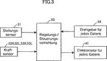
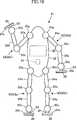
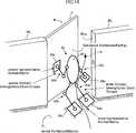
Wie in1 gezeigt, wird angenommen, dass ein mobiles Objekt101, welches N (N ≥ 2) Beingliedern103_1 bis103_N aufweist, welche mit einem Körper102 verbunden sind, ein mobiles Objekt ist, welches dazu in der Lage ist, sich auf einer Bodenfläche zu bewegen. Jedes von den Beingliedern103_1 bis103_N des mobilen Objekts101 weist eine Mehrzahl von Gelenken (nicht gezeigt) auf. Durch eine Verlagerung dieser Gelenke kann sich jedes von den Beingliedern103_1 bis103_N räumlich bewegen. Jedes Gelenk ist ein Rotationsgelenk oder ein Prismengelenk.As in 1 shown, is believed to be amobile object 101 , which N (N ≥ 2) leg links 103_1 to 103_N which has abody 102 connected, is a mobile object which is capable of moving on a floor surface. Each of the leg links 103_1 to 103_N of themobile object 101 has a plurality of joints (not shown). By shifting these joints, each of the leg joints can become 103_1 to 103_N move spatially. Each joint is a rotary joint or a prism joint.

Durch Aufsetzen (in Kontakt stehen mit der Bodenfläche) eines distalen Endes eines Standbeins, welches aus wenigstens einem Beinglied aus den N-Beingliedern103_1 bis103_N zusammengesetzt ist, kann das mobile Objekt101 sein eigenes Gewicht auf der Bodenfläche über das Standbein halten. Darüber hinaus kann das mobile Objekt101 durch räumliches Bewegen der Beinglieder103_1 bis103_N sich auf der Bodenfläche bewegen. Nachfolgend wird jedes von den Beingliedern103_1 bis103_N allgemein als das i-te Beinglied103_i (i = 1, 2, ..., N) oder ein Beinglied103_i bezeichnet.By placing (in contact with the bottom surface) a distal end of a supporting leg, which consists of at least one leg member of the N-leg members 103_1 to 103_N is composed, the mobile object can 101 keep your own weight on the floor above the support leg. In addition, themobile object 101 by spatially moving the leg links 103_1 to 103_N to move on the floor surface. Below is each of the leg links 103_1 to 103_N generally as the ith leg link 103_i (i = 1, 2, ..., N) or an leg link 103_i designated.

In einem beliebigen Bewegungszustand des mobilen Objekts101 wird eine Gesamtbodenreaktionskraft (Vektor), welche eine Bodenreaktionskraft ist, die insgesamt auf das mobile Objekt101 von der Bodenfläche wirkt, durch ↑FMt bezeichnet, eine Gesamttranslationsbodenreaktionskraft, welche ein Translatioskraftvektor von ↑FMt ist, durch ↑Ft bezeichnet, und ein Gesamtbodenreaktionskraftmoment, welches ein Momentvektor des ↑FMt ist, durch ↑Mt bezeichnet. In any movement state of themobile object 101 becomes a total floor reaction force (vector), which is a floor reaction force totaling themobile object 101 from the bottom surface acts, designated by ↑ FMt, a total translational floor reaction force, which is a translatio force vector of ↑ FMt, denoted by ↑ Ft, and a total floor reaction force moment, which is a moment vector of ↑ FMt, denoted by ↑ Mt.

Vorliegend sind die Gesamttranslationsbodenreaktionskraft ↑Ft und das Gesamtbodenreaktionskraftmoment ↑Mt jeweils als einen dreikomponentigen Vektor in einem Inertialkoordinatensystem (Koordinatensystem, welches bezüglich des Bodens fest ist) dargestellt. Die Gesamtbodenreaktionskraft ↑Ft wird als ein sechskomponentiger Spaltenvektor (= [↑Ft, ↑Mt]T) dargestellt, welcher durch Anordnen der Komponenten von ↑Ft und ↑Mt gebildet ist. Ein Wirkpunkt Pt der Gesamtbodenreaktionskraft ↑FMt ist ein Punkt auf der Bodenfläche.In the present case, the total translational floor reaction force ↑ Ft and the total floor reaction force moment ↑ Mt are each shown as a three-component vector in an inertial coordinate system (coordinate system fixed with respect to the ground). The total floor reaction force ↑ Ft is represented as a six-component column vector (= [↑ Ft, ↑ Mt]T ) formed by arranging the components of ↑ Ft and ↑ Mt. An action point Pt of the total floor reaction force ↑ FMt is a point on the floor surface.

In dieser Spezifikation wird das Symbol „T” dazu verwendet, um einen Vektor (Spaltenvektor) auszudrücken. Der Exponent „T” bezeichnet Transpositon. Als das inertiale Koordinatensystem zum Repräsentieren der Translationskraft, des Moments, der Position, der Stellung und dergleichen, wird als ein Beispiel zum Verdeutlichen, ein dreiachsiges orthogonales Koordinatensystem verwendet, dessen X-Achse eine Horizontalachse in eine Vorne-Hinten-Richtung des mobilen Objekts101 ist, dessen Z-Achse eine vertikale Richtung des mobilen Objekts101 ist und dessen Y-Achse eine Richtung ist (Rechts-Links-Richtung des mobilen Objekts101), welche zur X-Achse und zur Z-Achse orthogonal ist.In this specification, the symbol "T" is used to express a vector (column vector). The exponent "T" denotes transpositon. As the inertial coordinate system for representing the translational force, the moment, the position, the posture and the like, as an example for clarification, a three-axis orthogonal coordinate system whose X-axis is a horizontal axis in a front-rear direction of the mobile object is used 101 whose Z-axis is a vertical direction of themobile object 101 and whose Y-axis is a direction (right-left direction of the mobile object 101 ) which is orthogonal to the X-axis and the Z-axis.

Eine Bodenreaktionskraft (nachfolgend als eine i-te Bein-Bodenreaktionskraft oder eine Bein-Bodenreaktionskraft bezeichnet), welche auf das i-te Beinglied103_i (i = 1, 2, ..., N) von der Bodenfläche wirkt, wird durch ↑FM_i bezeichnet, eine Translationsbodenreaktionskraft, welche ein Translationskraftvektor von ↑FM_i ist, wird durch ↑F_i bezeichnet, und ein Bodenreaktionskraftmoment, welcher ein Momentvektor von ↑FM_i ist, wird durch ↑M_i bezeichnet.A floor reaction force (hereinafter referred to as an i-th leg floor reaction force or a leg floor reaction force) that points to the ith leg link 103_i (i = 1, 2, ..., N) from the bottom surface is denoted by ↑ FM_i, a translational floor reaction force which is a translational force vector of ↑ FM_i is denoted by ↑ F_i, and a floor reaction force moment which is a moment vector of ↑ FM_i is denoted by ↑ M_i.

Vorliegend werden die Translationsbodenreaktionskraft ↑F_i und das Bodenreaktionskraftmoment ↑M_i als ein dreikomponentiger Spaltenvektor in dem inertialen Koordinatensystem ausgedrückt, wie im Falle der Gesamtbodenreaktionskraft ↑FMt. Die i-te Bein-Bodenreaktionskraft ↑FM_i wird als ein sechskomponentiger Spaltenvektor (= [↑F_i, ↑M_i]T) ausgedrückt, welcher durch Anordnen der Komponenten von ↑F_i und ↑M_i gebildet wird. Ein Wirkpunkt P_i der i-ten Bein-Bodenreaktionskraft ↑FM_i ist ein Punkt auf der Bodenfläche innerhalb einer Grundfläche des i-ten Beinglieds103_i (d. h. innerhalb einer Kontaktfläche zwischen dem distalen Ende des i-ten Beinglieds103_i und der Bodenfläche).In the present case, the translational floor reaction force ↑ F_i and the floor reaction force moment ↑ M_i are expressed as a three-component column vector in the inertial coordinate system, as in the case of the total floor reaction force ↑ FMt. The i-th leg floor reaction force ↑ FM_i is expressed as a six-component column vector (= [↑ F_i, ↑ M_i]T ) formed by arranging the components of ↑ F_i and ↑ M_i. An action point P_i of the i-th leg floor reaction force ↑ FM_i is a point on the floor surface within a bottom surface of the ith leg member 103_i (ie, within a contact area between the distal end of the i-th leg member 103_i and the bottom surface).

Obwohl der Wirkpunkt P_i der i-ten Bein-Bodenreaktionskraft ↑FM_i nicht vorhanden ist, wenn das i-te Beinglied103_i nicht aufgesetzt ist (in dem Fall, dass ↑FM_i ein Nullvektor ist), wird angenommen, dass der Wirkpunkt P_i ein beliebig festgelegter Punkt ist (z. B. ein repräsentativer Punkt des distalen Endes des i-ten Beinglieds103_i).Although the action point P_i of the i-th leg floor reaction force ↑ FM_i is not present when the ith leg link 103_i is not set up (in the case that ↑ FM_i is a zero vector), it is assumed that the action point P_i is an arbitrarily set point (for example, a representative point of the distal end of the ith leg link 103_i ).

Eine Beziehung zwischen der Gesamtbodenreaktionskraft ↑FMt und der Bein-Bodenreaktionskraft ↑FM_i (i = 1, 2, ..., N) ist üblicherweise durch die folgende Gleichung (1) angegeben.A relationship between the total floor reaction force ↑ FMt and the leg floor reaction force ↑ FM_i (i = 1, 2, ..., N) is usually given by the following equation (1).

Figure 00100001
Figure 00100001

In der wobei-Klausel der Gleichung (1) sind die Komponenten „1” und „0” der Matrix AA_i eine Einheitsmatrix bzw. eine Nullmatrix und „x” ist das arithmetische Zeichen, welches ein Außenprodukt (Vektorprodukt) repräsentiert.In the where clause of the equation (1), the components "1" and "0" of the matrix AA_i are a unit matrix and a zero matrix, respectively, and "x" is the arithmetic character representing an outside product (vector product).

Vorliegend wird angenommen, dass eine Bodenreaktionskraft ↑FM_i (= [↑ΔF_i, ↑ΔM_i]T) für eine Störung zu dem Wirkpunkt P_i der i-ten Bein-Bodenreaktionskraft ↑FM_i hinzugefügt wird, wodurch eine Bodenreaktionskraft ↑ΔFMt (= [↑ΔFt, ↑ΔMt]T) für eine Störung dem Wirkpunkt Pt der Gesamtbodenreaktionskraft ↑FMt hinzugefügt wird. Es sei angemerkt, dass das Hinzufügen der Bodenreaktionskraft ↑ΔFM_i für Störung zu dem Wirkpunkt P_i bedeutet, dass die Bodenreaktionskraft, welche an dem Wirkpunkt P_i wirkt, von ↑FM_i auf ↑FM_i + ↑ΔFM_i geändert wird. Gleichermaßen bedeutet das Hinzufügen der Bodenreaktionskraft ↑ΔFMt für Störung zu dem Wirkpunkt Pt, dass die Bodenreaktionskraft, welche an dem Wirkpunkt Pt wirkt, von ↑FMt auf ↑FMt + ↑ΔFMt geändert wird.In the present case, it is assumed that a floor reaction force ↑ FM_i (= [↑ ΔF_i, ↑ ΔM_i]T ) for a disturbance is added to the action point P_i of the ith leg floor reaction force ↑ FM_i, whereby a floor reaction force ↑ ΔFMt (= [↑ ΔFt, ↑ ΔMt]T ) for a fault is added to the action point Pt of the total floor reaction force ↑ FMt. It should be noted that the addition of the floor reaction force ↑ ΔFM_i for disturbance to the action point P_i means that the floor reaction force acting on the action point P_i is changed from ↑ FM_i to ↑ FM_i + ↑ ΔFM_i. Likewise, adding the floor reaction force ↑ ΔFMt for disturbance to the point of action Pt means that the floor reaction force acting at the point of action Pt is changed from ↑ FMt to ↑ FMt + ↑ ΔFMt.

Nachfolgend wird ↑ΔFM_i als die i-te Bein-Störung-Bodenreaktionskraft bezeichnet und ein Translationskraftvektor ↑ΔF_i und ein Momentvektor ↑ΔM_i von ↑ΔFM_i werden jeweils als eine i-te Bein-Störung-Translationsbodenreaktionskraft und ein i-tes Bein-Störung-Bodenreaktionskraftmoment bezeichnet. Zusätzlich wird ↑ΔFMt als eine Störung-Gesamtbodenreaktionskraft bezeichnet und ein Translationskraftvektor ↑ΔFt und ein Momentvektor ↑ΔMt von ↑ΔFMt werden jeweils als eine Störung-Gesamttranslationsbodenreaktionskraft und als ein Störung-Gesamtbodenreaktionskraftmoment bezeichnet.Hereinafter, ↑ ΔFM_i is referred to as the i-th leg disturbance floor reaction force, and a translational force vector ↑ ΔF_i and a moment vector ↑ ΔM_i of ↑ ΔFM_i are respectively expressed as an i-th leg disturbance translational floor reaction force and i th leg disturbance floor reaction force moment designated. In addition, ↑ ΔFMt is referred to as a disturbance total floor reaction force, and a translational force vector ↑ ΔFt and a moment vector ↑ ΔMt of ↑ ΔFMt are respectively referred to as a disturbance total translational floor reaction force and a disturbance total floor reaction force moment.

Eine Beziehung zwischen der Störung-Gesamtbodenreaktionskraft ↑ΔFMt und der i-ten Bein-Störung-Bodenreaktionskraft ↑ΔFM_i (i = 1, 2, ..., N) wird durch die folgende Gleichung (2) basierend auf der Gleichung (1) gegeben.A relationship between the disturbance total floor reaction force ↑ ΔFMt and the i-th leg disturbance floor reaction force ↑ ΔFM_i (i = 1, 2, ..., N) is given by the following equation (2) based on the equation (1) ,

Figure 00110001
Figure 00110001

AA_i (i = 1, 2, ..., N) in der Gleichung (2) ist die gleiche wie die, die in der wobei-Klausel der Gleichung (1) definiert ist.AA_i (i = 1, 2, ..., N) in the equation (2) is the same as that defined in the where clause of the equation (1).

Es wird angenommen, dass die i-te Bein-Störung-Bodenreaktionskraft ↑ΔFM_i durch Federverlagerungen der Position und Stellung der Grundfläche (nachfolgend als die i-te Bein-Grundfläche bezeichnet) des i-ten Beinglieds103_i erzeugt wird. Im Einzelnen wird angenommen, dass die i-te Bein-Störung-Translationsbodenreaktionskraft ↑ΔF_i durch die Federverlagerung (Translationsverlagerung) der Position der i-ten Bein-Grundfläche erzeugt wird, und dass das i-te Bein-Störung-Bodenreaktionskraftmoment ↑ΔM_i durch die Federverlagerung (Rotationsverlagerung) der Stellung der i-ten Bein-Grundfläche erzeugt wird.It is assumed that the i-th leg disturbance floor reaction force ↑ ΔFM_i by spring displacements of the position and position of the base (hereinafter referred to as the i-th leg base) of the ith leg member 103_i is produced. Specifically, it is assumed that the i-th leg disturbance translational floor reaction force ↑ ΔF_i is generated by the spring displacement (translational displacement) of the ith leg base position, and the ith leg disturbance floor reaction force moment ↑ ΔM_i is determined by the Spring displacement (rotational displacement) of the position of the i-th leg base is generated.

Die Federverlagerungen der Position und Stellung der i-ten Bein-Grundfläche entsprechen jeweils einer Translationsverlagerung und einer Rotationsverlagerung durch eine elastische Verformung des Bodens in der i-ten Bein-Grundfläche oder einer elastischen Verformung des distalen Endes des i-ten Beinglieds103_1. The spring displacements of the position and position of the i-th leg base correspond to translational displacement and rotational displacement by elastic deformation of the bottom in the i-th leg surface or elastic deformation of the distal end of the ith leg member, respectively 103_1 ,

Der Verlagerungsbetrag der Position (Vektor des Betrages der Translationsverlagerung der i-ten Bein-Grundfläche in die Richtungen der drei Achsen, nachfolgend als ein Feder-Translationsverlagerungsbetrag bezeichnet) und der Betrag der Verlagerung der Stellung (Vektor des Betrages der Rotationsverlagerung der i-ten Bein-Grundfläche um die Richtung der drei Achsen, nachfolgend als ein Feder-Rotationverlagerungsbetrag bezeichnet) der i-ten Bein-Grundfläche durch die Federverlagerungen werden jeweils durch ↑Xorg_i und ↑Xrot_i bezeichnet. Eine Beziehung zwischen ↑Xorg_i und ↑ΔF_i beziehungsweise eine Beziehung zwischen ↑Xrot_i und ↑ΔM_i werden jeweils durch die folgenden Gleichungen (3) und (4) gegeben.↑ΔF_i = Korg_i·↑Xorg_i (3)↑ΔM_i = Krot_i·↑Xrot_i (4)Korg_i in der Gleichung (3) ist eine dreidimensionale Diagonalmatrix (nachfolgend als eine Translationsfederkonstantenmatrix Korg_i bezeichnet), deren Diagonalkomponenten Federkonstanten des Feder-Translationsverlagerungsbetrags ↑Xorg_i der i-ten Bein-Grundfläche sind. Krot_i in der Gleichung (4) ist eine dreidimensionale Diagonalmatrix (nachfolgend als eine Rotationsfederkonstantenmatrix Krot_i bezeichnet), dessen Diagonalkomponenten Federkonstanten der Komponenten des Feder-Rotationverlagerungsbetrags ↑Xrot_i der i-ten Bein-Grundfläche sind.The displacement amount of the position (vector of the amount of translational displacement of the ith leg base in the directions of the three axes, hereinafter referred to as a spring translational displacement amount) and the amount of displacement of the position (vector of the amount of rotational displacement of the ith leg Base area around the direction of the three axes, hereinafter referred to as a spring rotation displacement amount) of the i-th leg surface by the spring displacements are respectively denoted by ↑ Xorg_i and ↑ Xrot_i. A relationship between ↑ Xorg_i and ↑ ΔF_i and a relationship between ↑ Xrot_i and ↑ ΔM_i are given by the following equations (3) and (4), respectively. ↑ ΔF_i = Korg_i · ↑ Xorg_i (3) ↑ ΔM_i = Krot_i · ↑ Xrot_i (4) Korg_i in the equation (3) is a three-dimensional diagonal matrix (hereinafter referred to as a translation spring constant matrix Korg_i) whose diagonal components are spring constants of the spring translational displacement amount ↑ Xorg_i of the i-th leg surface. Krot_i in the equation (4) is a three-dimensional diagonal matrix (hereinafter referred to as a rotation spring constant matrix Krot_i) whose diagonal components are spring constants of the components of the spring rotational displacement amount ↑ Xrot_i of the ith leg surface.

Ferner wird angenommen, dass eine repräsentative Kontaktfläche eine einzelne virtuelle Kontaktfläche ist, welche alle Kontaktflächen zwischen den mobilen Objekt101 und der Bodenfläche (Grundflächen von allen Beingliedern103, welche aufgesetzt sind) darstellt. Es wird angenommen, dass die Gesamtbodenreaktionskraft ↑FMt auf das mobile Objekt101 in dieser repräsentativen Kontaktfläche wirkt. Die repräsentative Kontaktfläche, welche hier erwähnt wird, entspricht einem Stützpolygon.Further, it is assumed that a representative pad is a single virtual pad that covers all pads between themobile object 101 and the bottom surface (bases of allleg links 103 which are set up) represents. It is assumed that the total floor reaction force ↑ FMt on themobile object 101 acts in this representative contact area. The representative contact area mentioned here corresponds to a support polygon.

Es wird auch angenommen, dass die Störung-Gesamt-Bodenreaktionskraft ↑ΔFMt durch die Federverlagerung der Position und der Stellung der repräsentativen Kontaktfläche erzeugt wird, wie im Falle der i-ten Bein-Grundfläche. Im einzelnen, wird es angenommen, dass die Störung-Gesamttranslationsbodenreaktionskraft ↑ΔFt durch die Federverlagerung (Translationsverlagerung) der Position der repräsentativen Kontaktfläche erzeugt wird und dass das Störung-Gesamt-Bodenreaktionskraftmoment ↑ΔMt durch die Federverlagerung (Rotationsverlagerung) der Stellung der repräsentativen Kontaktfläche erzeugt wird.It is also assumed that the disturbance total floor reaction force ↑ ΔFMt is generated by the spring displacement of the position and the position of the representative pad, as in the case of the ith leg base. Specifically, it is assumed that the disturbance total translational floor reaction force ↑ ΔFt is generated by the spring displacement (translational displacement) of the position of the representative pad and that the disturbance total floor reaction force ↑ ΔMt is generated by the spring displacement (rotational displacement) of the position of the representative pad ,

Der Federtranslationsverlagerungsbetrag der Position (Vektor des Betrags an Translationsverlagerung in die Richtungen der drei Achsen durch die Federverlagerung) und der Federrotationsverlagerungsbetrag der Stellung (Vektor des Betrags von Rotationsverlagerung um die drei Achsen durch die Federverlagerung) der repräsentativen Kontaktfläche werden jeweils durch ↑Xc_org und ↑Xc_rot bezeichnet. Eine Beziehung zwischen ↑Xc_org und ↑ΔFt beziehungsweise zwischen ↑Xc_rot und ↑ΔMt werden durch die folgenden Gleichungen (5) und (6) gegeben.↑ΔFt = Kc_org·↑Xc_org (5)↑ΔMt = Kc_rot·↑Xc_rot (6)The spring translational displacement amount of the position (vector of the amount of translational displacement in the directions of the three axes by the spring displacement) and the spring rotational displacement amount of the position (vector of the amount of rotational displacement about the three axes by the spring displacement) of the representative contact surface are respectively represented by ↑ Xc_org and ↑ Xc_rot designated. A relationship between ↑ Xc_org and ↑ ΔFt and between ↑ Xc_rot and ↑ ΔMt, respectively, are given by the following equations (5) and (6). ↑ ΔFt = Kc_org · ↑ Xc_org (5) ↑ ΔMt = Kc_rot · ↑ Xc_red (6)

Kc_org in der Gleichung (5) ist eine dreidimensionale Diagonalmatrix (nachfolgend als eine Translationsfederkonstantenmatrix Kc_org bezeichnet), deren Diagonalkomponenten Federkonstanten der Komponenten des Federtranslationsverlagerungsbetrags ↑Xc_org der repräsentativen Kontaktfläche sind. Kc_rot in der Gleichung (6) ist eine dreidimensionale Diagonalmatrix (nachfolgend als eine Rotationsfederkonstantenmatrix Kc_rot bezeichnet), deren Diagonalkomponenten Federkonstanten der Komponenten des Federrotationsverlagerungsbetrags ↑Xc_rot der repräsentativen Kontaktfläche sind.Kc_org in the equation (5) is a three-dimensional diagonal matrix (hereinafter referred to as a translation spring constant matrix Kc_org) whose diagonal components are spring constants of the components of the spring translational displacement amount ↑ Xc_org of the representative contact surface. Kc_rot in the equation (6) is a three-dimensional diagonal matrix (hereinafter referred to as a rotation spring constant matrix Kc_rot) whose diagonal components are spring constants of the components of the spring rotational displacement amount ↑ Xc_rot of the representative contact surface.

In einem Zustand, in welchem nur ein Beinglied103_i des mobilen Objekts101 aufgesetzt ist, stimmt die repräsentative Kontaktfläche mit der Grundfläche (i-te Bein-Grundfläche) von diesem einzelnen Beinglied103_i überein. In einem solchen Zustand sind die Federverlagerungen der Position und Stellung der repräsentativen Kontaktfläche die gleichen, wie die Federverlagerungen der Position und Stellung der i-ten Bein-Grundfläche. Die jeweiligen Federverlagerungen entsprechen einer Translationsverlagerung und einer Rotationsverlagerung durch eine elastische Verformung des Bodens in der i-ten Bein-Grundfläche oder einer elastischen Verformung des distalen Endes des i-ten Beinglieds103_i.In a state in which only one leg link 103_i of themobile object 101 is set up, the representative contact area with the base area (i-th leg base) of this individual leg link agrees 103_i match. In such a state, the spring displacements of the position and position of the representative contact surface are the same as the spring displacements of the position and position of the i-th leg base. The respective spring displacements correspond to a translational displacement and a Rotational displacement by elastic deformation of the bottom in the i-th leg base or elastic deformation of the distal end of the ith leg member 103_i ,

In einem Zustand, in welchem zwei oder mehrere Beinglieder103 des mobilen Objekts101 aufgesetzt sind, dient andererseits die repräsentative Kontaktfläche als eine Grundfläche eines einzelnen virtuellen Grundbereichs, welcher Grundbereiche von allen Beingliedern103 kombiniert, die aufgesetzt sind. In einem solchen Zustand entsprechen die jeweiligen Federverlagerungen der Position und Stellung der repräsentativen Kontaktfläche einer Translationsverlagerung und einer Rotationsverlagerung durch eine elastische Verformung des Bodens in der Grundfläche des virtuellen Grundbereichs oder einer elastischen Verformung des virtuellen Grundbereichs.In a state in which two ormore leg links 103 of themobile object 101 On the other hand, the representative contact area serves as a base of a single virtual ground area, which is the basic area of allleg links 103 combined, which are put on. In such a state, the respective spring displacements correspond to the position and position of the representative contact surface of translational displacement and rotational displacement by elastic deformation of the bottom in the base area of the virtual base region or elastic deformation of the virtual base region.

Die folgende Gleichung (7) wird von der Gleichung (2) abgeleitet, in Bezug auf die Störung-Gesamttranslationsbodenreaktionskraft ↑ΔFt, welche zu dem Wirkpunkt Pt der Gesamtbodenreaktionskraft ↑FMt addiert wird, durch Addieren der i-ten Bein-Störung-Translationsbodenreaktionskraft ↑ΔF_i zu dem Wirkpunkt P_i der Bodenreaktionskraft für jedes i-te Bein ↑FM_i (i = 1, 2, ..., N).↑ΔFt = ↑ΔF_1 + ↑ΔF_2 + ... + ↑ΔF_N (7)The following equation (7) is derived from the equation (2) with respect to the disturbance total translational floor reaction force ↑ ΔFt, which is added to the action point Pt of the total floor reaction force ↑ FMt, by adding the i-th leg disturbance translational floor reaction force ↑ ΔF_i to the action point P_i of the floor reaction force for each ith leg ↑ FM_i (i = 1, 2, ..., N). ↑ ΔFt = ↑ ΔF_1 + ↑ ΔF_2 + ... + ↑ ΔF_N (7)

Aus den Gleichungen (3), (5) und (7) wird die folgende Gleichung (8) erhalten.Kc_org·↑Xc_org = Korg_1·↑Xorg_1 + Korg_2·↑Xorg_2 + ... + Korg_N·↑Xorg_N (8)From the equations (3), (5) and (7), the following equation (8) is obtained. Kc_org · ↑ Xc_org = Korg_1 · ↑ Xorg_1 + Korg_2 · ↑ Xorg_2 + ... + Korg_N · ↑ Xorg_N (8)

Es wird angenommen, dass der Wirkpunkt Pt der Gesamtbodenreaktionskraft ↑FMt vor der Addition der Störung-Gesamt-Bodenreaktionskraft ↑ΔFMt ein Mittelpunkt (COP) der Gesamtbodenreaktionskraft ist, und dass der Wirkpunkt P_i der i-ten Bein-Bodenreaktionskraft ↑FM_i vor der Addition der Störung-Bodenreaktionskraft des i-ten Beins ↑ΔFM_i ein Mittelpunkt der Bodenreaktionskraft auf der i-ten Bein-Grundfläche ist. Eine Beziehung zwischen einem Positionsvektor (bezeichnet durch ↑Pt) des Wirkpunkt Pt und einem Positionsvektor (bezeichnet durch ↑P_i) von jedem Wirkpunkt P_i (i = 1, 2, ..., N) bezüglich eines beliebigen Referenzpunkt wird durch die folgende Gleichung (9) angegeben.It is assumed that the action point Pt of the total floor reaction force ↑ FMt before the addition of the disturbance total floor reaction force ↑ ΔFMt is a center point (COP) of the total floor reaction force, and that the action point P_i of the ith leg floor reaction force ↑ FM_i before the addition of the Perturbation floor reaction force of the i-th leg ↑ ΔFM_i is a center of floor reaction force on the i-th leg base. A relationship between a position vector (designated by ↑ Pt) of the action point Pt and a position vector (denoted by ↑ P_i) of each action point P_i (i = 1, 2, ..., N) with respect to an arbitrary reference point is given by the following equation ( 9).

Es sei angemerkt, dass der Mittelpunkt der Gesamtbodenreaktionskraft der Wirkpunkt der Gesamtbodenreaktionskraft ↑FMt ist, in welcher die horizontale Komponente (Komponente um die horizontale Achse) des gesamten Bodenreaktionskraftsmoments ↑Mt um den Mittelpunkt der Gesamtbodenreaktionskraft Null ist. Gleichermaßen ist der Mittelpunkt der Bodenreaktionskraft der i-ten Bein-Grundfläche der Wirkpunkt der i-tes-Bein-Bodenreaktionskraft ↑FM_i, in welchem die horizontale Komponente (Komponente um die horizontale Achse) des Bodenreaktionskraftmoments ↑M_i um den Mittelpunkt der Bodenreaktionskraft gleich Null ist.↑Pt = r_1·↑P_1 + r_2·↑P_2 + ... + r_N·↑P_N (9)It should be noted that the center of the total floor reaction force is the point of action of the total floor reaction force ↑ FMt, in which the horizontal component (component about the horizontal axis) of the total floor reaction force moment ↑ Mt around the center of the total floor reaction force is zero. Likewise, the center of the floor reaction force of the ith leg floor is the action point of the ith floor floor reaction force ↑ FM_i in which the horizontal component (component about the horizontal axis) of the floor reaction force moment ↑ M_i around the center of the floor reaction force is zero , ↑ Pt = r_1 · ↑ P_1 + r_2 · ↑ P_2 + ... + r_N · ↑ P_N (9)

In der Gleichung (9) ist r_i (i = 1, 2, ..., N) ein Gewichtungskoeffizient, welcher durch r_i ≡ Fn_i/Fnt definiert ist. Fn_i (i = 1, 2, ..., N) ist ein Absolutwert einer Normalkraftkomponente (nachfolgend als eine Bodenfläche-Normalkraftkomponente bezeichnet), welche zur Bodenfläche senkrecht ist, der i-ten Bein-Translationsbodenreaktionskraft ↑F_i, und Fnt ist ein Absolutwert einer Normalkraftkomponente (Bodenfläche-Normalkraftkomponente), senkrecht zu der Bodenfläche, der Gesamttranslationsbodenreaktionskraft ↑Ft, wobei Fnt = Fn_1 + Fn_2 + ... + Fn_N ist. Dementsprechend ist der Gewichtungskoeffizient r_i ein Quotient der Bodenfläche-Normalkraftkomponente Fn_i der i-ten Bein-Translationsbodenreaktionskraft ↑F_i zu der Bodenfläche-Normalkraftkomponente Fnt der Gesamttranslationsbodenreaktionskraft ↑Ft, wobei 0 ≤ r_i ≤ 1 ist.In the equation (9), r_i (i = 1, 2, ..., N) is a weighting coefficient defined by r_i ≡ Fn_i / Fnt. Fn_i (i = 1, 2, ..., N) is an absolute value of a normal force component (hereinafter referred to as a bottom surface normal force component) which is perpendicular to the bottom surface, the ith leg translational floor reaction force ↑ F_i, and Fnt is an absolute value a normal force component (bottom surface normal force component) perpendicular to the bottom surface, the total translational floor reaction force ↑ Ft, where Fnt = Fn_1 + Fn_2 + ... + Fn_N. Accordingly, the weighting coefficient r_i is a quotient of the bottom surface normal force component Fn_i of the ith leg translational floor reaction force ↑ F_i to the bottom surface normal force component Fnt of the total translational floor reaction force ↑ Ft, where 0 ≤ r_i ≤ 1.

In dieser Spezifikation wird angenommen, dass Fn_i und Fnt mit der Vertikalkomponente (Z-Achsenkomponente) von ↑F_i und der Vertikalkomponente (Z-Achsenkomponente) von ↑Ft übereinstimmen oder im Wesentlichen übereinstimmen.In this specification, it is assumed that Fn_i and Fnt coincide or substantially coincide with the vertical component (Z-axis component) of ↑ F_i and the vertical component (Z-axis component) of ↑ Ft.

Es wird angenommen, dass die gleiche Beziehung wie in der Gleichung (9) zwischen dem Federtranslationsverlagerungsbetrag ↑Xc_org der Position der repräsentativen Kontaktfläche und dem Federtranslationsverlagerungsbetrag ↑Xorg_i der Position der i-ten Bein-Grundfläche ebenfalls gilt. Das heißt, es wird angenommen, dass die folgende Gleichung (10) gilt.↑Xc_org = r_1·↑Xorg_1 + r_2·↑Xorg_2 + ... + r_N·↑Xorg_N (10)It is assumed that the same relation as in the equation (9) also applies between the spring translational displacement amount ↑ Xc_org of the position of the representative contact surface and the spring translational displacement amount ↑ Xorg_i of the position of the ith leg surface. That is, it is assumed that the following equation (10) holds. ↑ Xc_org = r_1 · ↑ Xorg_1 + r_2 · ↑ Xorg_2 + ... + r_N · ↑ Xorg_N (10)

Die folgende Gleichung (11) wird von den Gleichungen (8) und (10) abgeleitet.Korg_i = r_i·Kc_org (11)The following equation (11) is derived from equations (8) and (10). Korg_i = r_i · Kc_org (11)

In der vorliegenden Erfindung wird die Gleichung (10) als eine Grundgleichung verwendet, die die Beziehung zwischen dem Federtranslationsverlagerungsbetrag ↑Xc_org der repräsentativen Kontaktflächen und dem Federtranslationsverlagerungsbetrag ↑Xorg_i der i-ten Bein-Grundfläche (i = 1, 2, ..., N) darstellt, und die Gleichung (11) wird als eine Grundgleichung verwendet, die die Beziehung zwischen der Translationsfederkonstantenmatrix Kc_org der repräsentativen Kontaktfläche und der Translationsfederkonstantenmatrix Korg_i der i-ten Bein-Grundfläche (i = 1, 2, ..., N) darstellt.In the present invention, the equation (10) is used as a basic equation which shows the relationship between the spring translational displacement amount ↑ Xc_org of the representative contact surfaces and the spring translational displacement amount ↑ Xorg_i of the ith leg surface (i = 1, 2, ..., N ), and equation (11) is used as a basic equation representing the relationship between the translation spring constant matrix Kc_org of the representative contact surface and the translation spring constant matrix Korg_i of the i-th leg base (i = 1, 2, ..., N) ,

Somit ist jede Diagonalkomponente (Federkonstante, welche sich auf die Translationsverlagerung in jeder von der Richtungen der drei Achsen bezieht) der Translationsfederkonstantenmatrix Korg_i der i-ten Bein-Grundfläche proportional zum Gewichtungskoeffizient r_i. Wenn der Gewichtungskoeffizient r_i groß ist (nahe an „1”), d. h. wenn der Quotient der Bodenfläche-Normalkraftkomponente Fn_i der translatorischen Bodenreaktionskraft des i-ten Beins ↑F_i zur Bodenfläche-Normalkraftkomponente Fnt der Gesamttranslationsbodenreaktionskraft ↑Ft höher ist, dann ist jede Diagonalkomponente der Translationsfederkonstantenmatrix Korg_i der i-ten Bein-Grundfläche größer. Mit anderen Worten, wenn der Quotient von Fn_i zu Fnt höher ist, ist die Änderungssensitivität des Federtranslationsverlagerungsbetrags ↑Xorg_i der i-ten Bein-Grundfläche im Verhältnis zur erforderlichen i-te Bein-Störung-Translationsbodenreaktionskraft höher.Thus, each diagonal component (spring constant related to the translational displacement in each of the directions of the three axes) of the translational spring constant matrix Korg_i of the ith leg base is proportional to the weighting coefficient r_i. When the weighting coefficient r_i is large (close to "1"), d. H. when the quotient of the floor surface normal force component Fn_i of the translational floor reaction force of the ith leg ↑ F_i to the floor surface normal force component Fnt of the total translational floor reaction force ↑ Ft is higher, then each diagonal component of the translational spring constant matrix Korg_i of the ith leg floor area is larger. In other words, when the quotient of Fn_i to Fnt is higher, the change sensitivity of the spring translational displacement amount ↑ Xorg_i of the ith leg base is higher in proportion to the required ith leg disturbance translational floor reaction force.

In einem Zustand, in welchem nur das i-te Beinglied103_i aufgesetzt ist (r_i = 1), stimmen die i-te Bein-Grundfläche und die entsprechende Kontaktfläche überein, so dass die Translationsfederkonstantenmatrix Korg_i der i-ten Bein-Grundfläche und die Translationsfederkonstantenmatrix Kc_org der repräsentativen Kontaktfläche übereinstimmen. Darüber hinaus stimmen, da ↑ΔF_i = ↑ΔFt der Federtranslationsverlagerungsbetrag ↑Xorg_i der i-ten Bein-Grundfläche und der Federtranslationsverlagerungsbetrag ↑Xc_org der repräsentativen Kontaktfläche überein.In a state in which only the i-th leg link 103_i is set (r_i = 1), the i-th leg surface and the corresponding contact surface coincide so that the translation spring constant matrix Korg_i of the i-th leg surface and the translation spring constant matrix Kc_org of the representative contact surface coincide. Moreover, since ↑ ΔF_i = ↑ ΔFt, the spring translational displacement amount ↑ Xorg_i of the ith leg surface and the spring translational displacement amount ↑ Xc_org of the representative contact surface coincide.

In einem Zustand, in welchem zwei oder mehrere Beinglieder103 aufgesetzt sind, ist andererseits der Federtranslationsverlagerungsbetrag ↑Xc_org der repräsentativen Kontaktfläche ein gewichteter Mittelwert (gewichteter Mittelwert mit r_i als der Gewichtungskoeffizient) der Beträge der Translationsverlagerung der Feder ↑Xorg_i der i-ten Bein-Grundflächen, die den Beingliedern103_i entsprechen und nicht den nicht aufgesetzten Beingliedern.In a state in which two ormore leg links 103 On the other hand, the spring translational displacement amount ↑ Xc_org of the representative contact surface is a weighted average (weighted average with r_i as the weighting coefficient) of the amounts of translation displacement of the spring ↑ Xorg_i of the ith leg surfaces corresponding to the leg links 103_i correspond and not the unassembled leg links.

Die folgende Gleichung (12) wird von der Gleichung (2) abgeleitet bezüglich des Störung-Gesamtbodenreaktionskraftmoments ↑ΔMt, welcher zu dem Wirkpunkt Pt der Gesamtbodenreaktionskraft ↑FMt addiert wird, durch Addieren des Störung-Bodenreaktionskraftmoments ↑ΔM_i des i-ten Beins zu dem Wirkpunkt P_i der i-ten Bein-Bodenreaktionskraft ↑FM_i (i = 1, 2, ..., N) in einem Zustand, in welchem die jeweiligen Translationsbodenreaktionskräfte ↑F_1 bis ↑F_N der Bodenreaktionskräfte ↑FM_1 bis ↑FM_N des ersten bis N-ten Glied fest sind.↑ΔMt = ↑ΔM_1 + ↑ΔM_2 + ... + ↑ΔM_N (12)The following equation (12) is derived from the equation (2) with respect to the disturbance total floor reaction force ↑ ΔMt which is added to the action point Pt of the total floor reaction force ↑ FMt by adding the disturbance floor reaction force moment ↑ ΔM_i of the ith leg to the action point P_i of the i-th leg floor reaction force ↑ FM_i (i = 1, 2, ..., N) in a state in which the respective translational floor reaction forces ↑ F_1 to ↑ F_N of the floor reaction forces ↑ FM_1 to ↑ FM_N of the first to N-th Limb are tight. ↑ ΔMt = ↑ ΔM_1 + ↑ ΔM_2 + ... + ↑ ΔM_N (12)

Aus den Gleichungen (4), (6) und (12) wird die folgende Gleichung (13) erhalten.Kc_rot·↑Xc_rot = Krot_1·↑Xrot_1 + Krot_2·↑Xrot_2 + ... + Krot_N·↑Xrot_N (13)From the equations (4), (6) and (12), the following equation (13) is obtained. Kc_rot · ↑ Xc_rot = Krot_1 · ↑ Xrot_1 + Krot_2 · ↑ Xrot_2 + ... + Krot_N · ↑ Xrot_N (13)

In dem Fall, in welchem der Wirkpunkt P_i der i-ten Bein-Bodenreaktionskraft ↑FM_i mit dem Mittelpunkt der Bodenreaktionskraft der i-ten Bein-Grundfläche übereinstimmt, ist ein Addieren des Störung-Gesamtbodenreaktionskraftmoment ↑ΔM_i des i-ten Beins zu dem Wirkpunkt P_i (Mittelpunkt der Bodenreaktionskraft) der i-ten Bein-Bodenreaktionskraft in einem Zustand, in welchem die jeweiligen translatorischen Bodenreaktionskräfte ↑F_1 bis ↑F_N der Bodenreaktionskräfte ↑FM_1 bis ↑FM_N des ersten Beins fest sind, einer Verschiebung der horizontalen Position des Mittelpunkts der Bodenreaktionskraft in der i-ten Bein-Grundfläche vom Punkt P_i aus äquivalent.In the case where the action point P_i of the ith leg floor reaction force ↑ FM_i coincides with the center of the floor reaction force of the ith leg floor, adding the disturbance total floor reaction force moment ↑ ΔM_i of the ith leg to the action point P_i (Center of the floor reaction force) of the i-th leg floor reaction force in a state in which the respective floor translational reaction forces ↑ F_1 to ↑ F_N of the floor reaction forces ↑ FM_1 to ↑ FM_N of the first leg are fixed, a shift of the horizontal position of the center of the floor reaction force in FIG the i-th leg base from the point P_i equivalent.

Gleichermaßen ist in dem Fall, in welchem der Wirkpunkt Pt der Gesamtbodenreaktionskraft ↑FMt mit dem Mittelpunkt m(COP) der Gesamtbodenreaktionskraft übereinstimmt, ist ein Addieren des Störung-Gesamtbodenreaktionskraftmoment ↑ΔMt zu dem Wirkpunkt Pt der Gesamtbodenreaktionskraft ↑FMt, einer Verschiebung der horizontalen Position des Mittelpunkt der Gesamtbodenreaktionskraft vom Punkt Pt aus äquivalent.Similarly, in the case where the action point Pt of the total floor reaction force ↑ FMt coincides with the center floor m (COP) of the total floor reaction force, adding the disturbance total floor reaction force moment ↑ ΔMt to the action point Pt of the total floor reaction force ↑ FMt is a shift of the horizontal position of the Center of total floor reaction force equivalent from point Pt.

In diesem Fall werden, wenn der Verlagerungsbetrag (zweikomponentiger Verlagerungsbetragsvektor) der horizontalen Position des Mittelpunkts der Bodenreaktionskraft in der i-ten Bein-Grundfläche durch ↑ΔRpt_i und der Verlagerungsbetrag (zweikomponentiger Verlagerungsbetragsvektor) der horizontalen Position des Mittelpunkt der Gesamtbodenreaktionskraft durch ↑ΔCOP bezeichnet ist, die Komponente um die Horizontalachse (Komponente um die X-Achse und die Y-Achse) des ↑ΔCOP·Fnt ≈ ↑ΔMt und die Komponente um die Horizontalachse (Komponente um die X-Achse und die Y-Achse) des ↑ΔRpt_i·Fn_i ≈ ↑ΔM_i erhalten. Somit wird die folgende Gleichung (14) aus der Gleichung (12) abgeleitet.↑ΔCOP = r_1·↑ΔRpt_1 + r_2·↑ΔRpt_2 + ... + r_N·↑ΔRpt_N (14) In this case, when the displacement amount (two-component displacement amount vector) of the horizontal position of the floor reaction force's center point in the ith leg surface is denoted by ↑ ΔRpt_i and the displacement amount (two-component displacement amount vector) of the horizontal position of the center of the total floor reaction force by ↑ ΔCOP, the component about the horizontal axis (component about the X-axis and the Y-axis) of the ↑ ΔCOP · Fnt ≈ ↑ ΔMt and the component about the horizontal axis (component about the X-axis and the Y-axis) of the ↑ ΔRpt_i · Fn_i ≈ ↑ ΔM_i received. Thus, the following equation (14) is derived from the equation (12). ↑ ΔCOP = r_1 · ↑ ΔRpt_1 + r_2 · ↑ ΔRpt_2 + ... + r_N · ↑ ΔRpt_N (14)

In der Gleichung (14) ist r_i (i = 1, 2, ..., N) der oben erwähnte Gewichtungskoeffizient r_i (≡ Fn_i/Fnt).In the equation (14), r_i (i = 1, 2, ..., N) is the above-mentioned weighting coefficient r_i (≡ Fn_i / Fnt).

Da die Grundflächen des ersten bis n-ten Beins Abschnitte auf der gemeinsamen Bodenfläche sind, gilt in dem Fall, in welchem die gleiche Bodenfläche-Normalkraftkomponente Fn_i auf jede der Grundflächen des ersten bis n-ten Beins wirkt, die gleiche Beziehung zwischen dem Störung-Bodenreaktionskraftmoment (= ↑ΔRpt_i·Fn_i), welcher dem Verlagerungsbetrag ↑ΔRpt_i der horizontalen Position des Mittelpunkts der Bodenreaktionskraft der i-ten Bein-Grundfläche entspricht, und der Komponente um die horizontale Achse in dem Rotationsverlagerungsbetrag ↑Xrot_i durch die Federverlagerung der i-ten Bein-Grundfläche, für jede i-te Bein-Grundfläche.Since the bases of the first through n-th legs are portions on the common bottom surface, in the case where the same ground surface normal force component Fn_i acts on each of the bases of the first through n-th legs, the same relationship between the interference Floor reaction force moment (= ↑ ΔRpt_i · Fn_i) corresponding to the displacement amount ↑ ΔRpt_i of the horizontal position of the floor reaction force center of the ith leg base, and the component about the horizontal axis in the rotation displacement amount ↑ Xrot_i by the spring displacement of the ith leg Basic surface, for every i-th leg surface.

Dies zeigt, dass die folgende Gleichung (15) in dem Fall gilt, in welchem die gleiche Bodenfläche-Normalkraftkomponente Fn_i (bezeichnet durch Fna) auf jeder der Grundflächen des ersten bis n-ten Beins liegt.↑ΔRpt_i·Fna = Krot·↑Xrot_i_xy (15)wobei ↑Xrot_i_xy die Komponente um die Horizontalachse (Komponente um die X-Achse und die Y-Achse) in dem Federrotationsverlagerungsbetrag ↑Xrot_i der i-ten Bein-Grundfläche ist, und Krot die zweidimensionale Diagonalmatrix (Federkonstanten-Matrix) bezüglich der Drehung um die X-Achse und die Y-Achse) ist.This shows that the following equation (15) holds in the case where the same ground surface normal force component Fn_i (denoted by Fna) lies on each of the bases of the first to nth legs. ↑ ΔRpt_i · Fna = Krot · ↑ Xrot_i_xy (15) where ↑ Xrot_i_xy is the component about the horizontal axis (component about the X-axis and the Y-axis) in the spring rotational displacement amount ↑ Xrot_i of the ith leg base, and Krot the two-dimensional diagonal matrix (spring constant matrix) for rotation about X-axis and the Y-axis).

Gegeben, dass die Gleichung (15) gleichermaßen für die repräsentative Kontaktfläche gilt, wird die folgende Gleichung (16) erhalten.↑ΔCOP·Fna = Krot·↑Xc_rot_xy (16)wobei ↑Xrot_xy die Komponente um die Horizontalachse (Komponente um die X-Achse und die Y-Achse) in dem Federrotationsverlagerungsbetrag ↑Xc_rot der Grundfläche der repräsentativen Kontaktfläche ist.Given that equation (15) applies equally to the representative contact area, the following equation (16) is obtained. ↑ ΔCOP · Fna = Krot · ↑ Xc_rot_xy (16) where ↑ Xrot_xy is the component about the horizontal axis (component about the X-axis and the Y-axis) in the spring rotational displacement amount ↑ Xc_rot of the area of the representative contact surface.

Aus den Gleichungen (14) bis (16) wird folgende Gleichung (17) erhalten.Krot·↑Xc_rot_xy = r_1·Krot·↑Xrot_1_xy + r_2·Krot·↑Xrot_2_xy + ... + r_N·Krot·↑Xrot_N_xy (17)From equations (14) to (16), the following equation (17) is obtained. Krot · ↑ Xc_rot_xy = r_1 · Krot · ↑ Xrot_1_xy + r_2 · Krot · ↑ Xrot_2_xy + ... + r_N · Krot · ↑ Xrot_N_xy (17)

Aus der Gleichung (17) wird die folgende Gleichung (18) erhalten.↑Xc_rot_xy = r_1·↑Xrot_1_xy + r_2·↑Xrot_2_xy + ... + r_N·↑Xrot_N_xy (18)From the equation (17), the following equation (18) is obtained. ↑ Xc_rot_xy = r_1 · ↑ Xrot_1_xy + r_2 · ↑ Xrot_2_xy + ... + r_N · ↑ Xrot_N_xy (18)

In der vorliegenden Erfindung wird angenommen, dass die gleiche Beziehung aus der Gleichung (18) für alle Komponenten (drei Komponenten) zwischen dem Federrotationsverlagerungsbetrag ↑Xc_rot der repräsentativen Kontaktfläche und dem Betrag der Rotationsverlagerungsfeder ↑Xrot_i der i-ten Bein-Grundfläche gilt. Das heißt, es wird angenommen, dass die folgende Gleichung (19) gilt.↑Xc_rot = r_1·↑Xrot_1 + r_2·↑Xrot_2 + ... + r_N·↑Xrot_N (19)In the present invention, it is assumed that the same relationship applies from the equation (18) for all components (three components) between the spring rotational displacement amount ↑ Xc_rot of the representative contact surface and the amount of the rotational displacement spring ↑ Xrot_i of the i-th leg base. That is, it is assumed that the following equation (19) holds. ↑ Xc_rot = r_1 · ↑ Xrot_1 + r_2 · ↑ Xrot_2 + ... + r_N · ↑ Xrot_N (19)

Die folgende Gleichung (20) wird von den Gleichungen (13) und (19) abgeleitet.Krot_i = r_i·Kc_rot (20)The following equation (20) is derived from equations (13) and (19). Krot_i = r_i · Kc_rot (20)

In der vorliegenden Erfindung wird die Gleichung (19) als eine Basisgleichung verwendet, welche die Beziehung zwischen dem Federrotationsverlagerungsbetrag ↑Xc_rot der repräsentativen Kontaktfläche und dem Federrotationsverlagerungsbetrag ↑Xrot_i der i-ten Bein-Grundfläche (i = 1, 2, ..., N) darstellt, und die Gleichung (20) wird als eine Grundgleichung verwendet, welche die Beziehung zwischen der Rotation-Federkonstanten-Matrix Kc_rot der repräsentativen Kontaktfläche und der Rotation-Federkonstanten-Matrix Krot_i der i-ten Bein-Grundfläche (i = 1, 2, ..., N) darstellt.In the present invention, the equation (19) is used as a basic equation which shows the relationship between the spring rotational displacement amount ↑ Xc_rot of the representative contact surface and the spring rotational displacement amount ↑ Xrot_i of the ith leg base (i = 1, 2, ..., N ), and the Equation (20) is used as a basic equation which expresses the relationship between the rotation-spring constant matrix Kc_rot of the representative contact surface and the rotation-spring constant matrix Krot_i of the i-th leg surface (i = 1, 2,. N).

Somit ist die Diagonalkomponente (Federkonstante bezogen auf die Rotationsverlagerung um jede der drei Achsen) der Rotationsfederkonstantenmatrix Krot_i der i-ten Bein-Grundfläche proportional zum Gewichtungskoeffizienten r_i. Wenn der Gewichtungskoeffizient r_i groß ist (näher an „1”), d. h. wenn der Quotient aus der Bodenflächen-Normalkomponente Fn_i der i-ten Bein-Translationsbodenreaktionskraft ↑Fn_i zu der Bodenfläche-Normalkraftkomponente Fnt der gesamten translatorischen Bodenreaktionskraft ↑Ft höher ist, dann ist jede Diagonalkomponente der Rotationsfederkonstanten-Matrix Krot_i der i-ten Bein-Grundfläche größer. Mit anderen Worten ist, wenn der Quotient von Fn_i zu Fnt höher ist, die Änderungssensitivität des Betrags der Rotationsverlagerung der Feder ↑Xrot_i der i-ten Bein-Grundfläche gegenüber dem erforderlichen i-ten Bein-Störung-Bodenreaktionskraftmoment höher.Thus, the diagonal component (spring constant with respect to the rotational displacement about each of the three axes) of the rotational spring constant matrix Krot_i of the i-th leg base is proportional to the weighting coefficient r_i. When the weighting coefficient r_i is large (closer to "1"), d. H. when the quotient of the bottom surface normal component Fn_i of the ith leg translational floor reaction force ↑ Fn_i to the bottom surface normal force component Fnt of the total translational floor reaction force ↑ Ft is higher, then each diagonal component of the rotational spring constant matrix Krot_i of the ith leg base is larger , In other words, when the quotient of Fn_i to Fnt is higher, the change sensitivity of the amount of rotational displacement of the spring ↑ Xrot_i of the ith leg base is higher than the required ith leg interference floor reaction force torque.

In einem Zustand, in welchem nur das i-te Beinglied103_i aufgesetzt ist (r_i = 1), stimmen die i-te Bein-Grundfläche mit der repräsentativen Kontakfläche überein, so dass die Rotationsfederkonstanten-Matrix Krot_i mit der i-ten Bein-Grundfläche und die Rotationsfederkonstanten-Matrix Kc_rot der repräsentativen Kontaktfläche miteinander übereinstimmen. Darüber hinaus stimmen, da ↑ΔMt_i = ↑ΔMt ist, der Federrotationsverlagerungsbetrag ↑Xrot_i der i-ten Bein-Grundfläche und der Federrotationsverlagerungsbetrag ↑Xc_rot der repräsentativen Kontaktfläche miteinander überein.In a state in which only the i-th leg link 103_i is set (r_i = 1), the i-th leg surface coincides with the representative contact surface, so that the rotation spring constant matrix Krot_i with the i-th leg surface and the rotation spring constant matrix Kc_rot of the representative contact surface coincide with each other. Moreover, since ↑ ΔMt_i = ↑ ΔMt, the spring rotational displacement amount ↑ Xrot_i of the i-th leg base and the spring rotational displacement amount ↑ Xc_rot of the representative contact surface coincide with each other.

In einem Zustand, in welchem zwei oder mehrere Beinglieder103 aufgesetzt sind, ist andererseits der Federrotationsverlagerungsbetrag ↑Xc_rot der repräsentativen Kontaktfläche ein gewichteter Mittelwert (gewichteter Mittelwert mit r_i als der Gewichtungskoeffizient) der Beträge der Rotationsverlagerung der Feder ↑Xrot_i der i-ten Bein-Grundflächen welche dem Beinglied103_i entsprechen, und nicht den nicht aufgesetzten Beingliedern.In a state in which two ormore leg links 103 On the other hand, the spring rotational displacement amount ↑ Xc_rot of the representative contact surface is a weighted average (weighted average r_i as the weighting coefficient) of the amounts of rotational displacement of the spring ↑ Xrot_i of the ith leg surfaces which the leg link 103_i and not the unassembled leg links.

Als nächstes wird die folgende Gleichung (21) durch Anwenden der Gleichungen (3) bis (6) auf die Gleichung (20) und ferner Anwenden der Gleichungen (11) und (20).Next, the following equation (21) is applied by applying the equations (3) to (6) to the equation (20) and further applying the equations (11) and (20).

Figure 00220001
Figure 00220001

Die Gleichungen (11) und (20) basieren auf der Annahme, dass der Wirkpunkt Pt der Gesamtbodenreaktionskraft ↑FMt der Mittelpunkt der Gesamtbodenreaktionskraft ist und dass der Wirkpunkt P_i der Bodenreaktionskraft ↑FM_i der i-ten Beins der Mittelpunkt der Bodenreaktionskraft der i-ten Bein-Grundfläche ist. Es sein angenommen, dass ↑V_i der Positionsvektor des Mittelpunkts der Bodenreaktionskraft der i-ten Bein-Grundfläche relativ zum Wirkpunkt Pt als der Wirkpunkt der Gesamtbodenreaktionskraft ist. Dann ist VV_i (i = 1, 2, ..., N) in der Gleichung (21) eine Matrix, die wie folgt definiert ist.VV_i: Matrix, so dass VV_i·↑F_i = V_i × ↑F_iwobei ↑V i der Positionsvektor des Mittelpunkts der Bodenreaktionskraft der i-ten Bein-Grundfläche relativ zum Mittelpunkt der Gesamtbodenreaktionskraft ist.The equations (11) and (20) are based on the assumption that the action point Pt of the total floor reaction force ↑ FMt is the center of the total floor reaction force, and that the action point P_i of the floor reaction force ↑ FM_i of the i-th leg is the center of the floor reaction force of the ith leg Basis is. Suppose that ↑ V_i is the position vector of the center of the floor reaction force of the ith leg base relative to the point of action Pt as the point of action of the total floor reaction force. Then, VV_i (i = 1, 2, ..., N) in the equation (21) is a matrix defined as follows. VV_i: matrix such that VV_i * ↑ F_i = V_i × ↑ F_i where ↑ V i is the position vector of the center of the floor reaction force of the ith leg base relative to the center of the total floor reaction force.

Ausführlicher betrachtet, ist der Mittelpunkt der Gesamtbodenreaktionskraft der Mittelpunkt der Gesamtbodenreaktionskraft, welche der Gesamtbodenreaktionskraft ↑FMt entspricht vor der Addition der Störung-Gesamtbodenreaktionskraft ↑ΔFMt, und dem Mittelpunkt der Bodenreaktionskraft der i-ten Bein-Grundfläche ist der Mittelpunkt der Bodenreaktionskraft, welche der i-ten Bein-Bodenreaktionskraft ↑FM_i entspricht vor der Addition der Steuerung-Bodenreaktionskraft des i-ten Beins ↑ΔFM_i.In more detail, the center of the total floor reaction force is the center of the floor reaction force ↑ FMt prior to addition of the disturbance total floor reaction force ↑ ΔFMt, and the center of the floor reaction force of the ith leg floor is the center of the floor reaction force corresponding to the i leg floor reaction force ↑ FM_i corresponds to the addition of the control floor reaction force of the ith leg ↑ ΔFM_i.

Die folgende Gleichung (22) wird von der Gleichung (21) abgeleitet.The following equation (22) is derived from the equation (21).

Figure 00230001
Figure 00230001

Gegeben, dass ein generalisierter Variablenvektor ↑q1, dessen Komponenten die Position (Position in den Richtungen der drei Achsen) und die Stellung (Stellungswinkel um die drei Achsen) des Körpers102 des mobilen Objekts101 und der Betrag an Verlagerung von jedem Gelenk des mobilen Objekts101 sind, ↑Xc ein Verlagerungsbetragsvektor (= [↑Xc_org, ↑Xc_rot]T), welcher aus dem Federtranslationsverlagerungsbetrag ↑Xc_org der Position der repräsentativen Kontaktfläche und dem Federrotationsverlagerungsbetrag ↑Xc_rot der Stellung der repräsentativen Kontaktfläche besteht, und ↑X_i ein Verlagerungsbetragvektor (= [↑Xc_org, ↑Xc_rot]T), welcher aus dem Federtranslationsverlagerungsbetrag ↑Xorg_i der Position der i-ten Bein-Grundfläche und dem Federrotationsverlagerungsbetrag ↑Xrot_i der Stellung der i-ten Bein-Grundfläche besteht. Nachfolgend wird ↑Xc als ein Betrag der Translations-/Rotationsverlagerung der Feder der repräsentativen Kontaktfläche bezeichnet, und ↑X_i wird als ein Betrag der Translations-/Rotationsverlagerung der Feder der i-ten Bein-Grundfläche bezeichnet. Im Einzelnen ist der generalisierte Variablenvektor ↑q1 ein Spaltenvektor, welcher durch Anordnung der sechs Komponenten der Position und Stellung des Körpers102 und des Betrags an Verlagerung von jedem Gelenk des mobilen Objekts101 gebildet ist.Given that a generalized variable vector ↑ q1, whose components are the position (position in the directions of the three axes) and the position (attitude angle around the three axes) of thebody 102 of themobile object 101 and the amount of displacement of each joint of themobile object 101 , ↑ Xc is a displacement amount vector (= [↑ Xc_org, ↑ Xc_rot]T ) consisting of the spring translational displacement amount ↑ Xc_org of the position of the representative contact surface and the spring rotational displacement amount ↑ Xc_rot of the position of the representative contact surface, and ↑ X_i is a displacement amount vector (= [↑ Xc_org, ↑ Xc_rot]T ) consisting of the spring translational displacement amount ↑ Xorg_i of the position of the i-th leg base and the spring rotational displacement amount ↑ Xrot_i of the position of the i-th leg base. Hereinafter, ↑ Xc is referred to as an amount of translational / rotational displacement of the spring of the representative contact surface, and ↑ X_i is referred to as an amount of translational / rotational displacement of the spring of the i-th leg base. Specifically, the generalized variable vector ↑ q1 is a column vector, which is determined by arranging the six components of the position and position of thebody 102 and the amount of displacement of each joint of themobile object 101 is formed.

Wenn der Translations-/Rotationsverlagerungsbetrag der Feder ↑Xc der repräsentativen Kontaktfläche als der Betrag an Verlagerung (zeitliche Änderungsrate) der Position und der Stellung der repräsentativen Kontaktfläche pro Zeiteinheit angesehen wird, wird eine Jacobimatrix, welche eine Beziehung zwischen dem Betrag an Verlagerung der Disposition und der Stellung der repräsentativen Kontaktfläche pro Zeiteinheit und dem Betrag an Veränderung (zeitliche Änderungsrate) ↑Δq1 des generalisierten Variablenvektors ↑q1 pro Zeiteinheit darstellt, als eine Matrix Jc ausgedrückt, welche die Beziehung zwischen ↑Xc und ↑Δq1 durch die folgende Gleichung (23) repräsentiert. Vorliegend ist ↑Δq1 ein Spaltenvektor, welcher durch Anordnung der Änderungsbeträge der Komponenten des generalisierten Variablenvektors ↑q1 pro Zeiteinheit gebildet wird.↑Xc = Jc·↑Δq1 (23)When the translational / rotational displacement amount of the representative contact surface spring ↑ Xc is regarded as the amount of displacement (temporal change rate) of the position and the position of the representative contact surface per unit time, a Jacobian matrix showing a relationship between the amount of displacement of the disposition and represents the position of the representative contact area per unit time and the amount of change (rate of change) ↑ Δq1 of the generalized variable vector ↑ q1 per unit time, expressed as a matrix Jc representing the relationship between ↑ Xc and ↑ Δq1 by the following equation (23) , In the present case, ↑ Δq1 is a column vector formed by arranging the change amounts of the components of the generalized variable vector ↑ q1 per unit time. ↑ Xc = Jc · ↑ Δq1 (23)

Gleichermaßen, wenn der Betrag der Translations-/Rotationsverlagerung der Feder der i-ten Bein-Grundfläche als der Betrag an Verlagerung (zeitliche Änderungsrate) der Position und der Stellung der i-ten Bein-Grundfläche pro Zeiteinheit angesehen wird, wird eine Jacobimatrix, welche eine Beziehung zwischen dem Betrag an Verlagerung der Position und der Stellung der i-ten Bein-Grundfläche pro Zeiteinheit darstellt und dem Betrag an Änderung (zeitliche Änderungsrate) ↑Δq1 des generalisierten Variablenvektors ↑q1 pro Zeiteinheit als eine Matrix J_i ausgedrückt, welche die Beziehung zwischen ↑X_i und ↑Δq1 durch die folgende Gleichung (24) darstellt.↑X_i = J_i·↑Δq1 (24)Similarly, when the amount of translational / rotational displacement of the spring of the i-th leg base is regarded as the amount of displacement (rate of change) of the position and the position of the i-th leg base per unit time, a Jacobian matrix becomes represents a relationship between the amount of displacement of the position and the position of the i-th leg base per unit time and the amount of change (rate of change) ↑ Δq1 of the generalized variable vector ↑ q1 per unit time as a matrix J_i representing the relationship between ↑ X_i and ↑ Δq1 by the following equation (24). ↑ X_i = J_i · ↑ Δq1 (24)

Sei Jc_org eine Jacobimatrix, welche eine Beziehung zwischen dem Betrag an Verlagerung der Position der repräsentativen Kontaktfläche pro Zeiteinheit und ↑Δq1 darstellt (d. h. eine Matrix, welche die Beziehung zwischen ↑Xc_org und ↑Δq1 durch die folgende Gleichung (25a) darstellt) und Jc_rot sei eine Jacobimatrix, welche eine Beziehung zwischen dem Betrag an Verlagerung der Stellung der repräsentativen Kontaktfläche pro Zeiteinheit und ↑Δq1 darstellt (d. h. eine Matrix, welche die Beziehung zwischen ↑Δxc_rot und ↑Δq1 durch die folgende Gleichung (25b) darstellt). Dann ist Jc = [↑Jc_org, ↑Jc_rot]T, wie in der Gleichung (25c) gezeigt.↑Xc_org = Jc_org·↑Δq1 (25a)↑Xc_rot = Jc_rot·↑Δq1 (25b)Jc = [Jc_org, Jc_rot]T (25c)Let Jc_org be a Jacobian matrix representing a relationship between the amount of displacement of the position of the representative contact area per unit time and ↑ Δq1 (ie, a matrix representing the relationship between ↑ Xc_org and ↑ Δq1 by the following equation (25a)) and Jc_rot a Jacobian matrix representing a relationship between the amount of displacement of the position of the representative contact area per unit time and ↑ Δq1 (ie, a matrix representing the relationship between ↑ Δxc_rot and ↑ Δq1 by the following equation (25b)). Then, Jc = [↑ Jc_org, ↑ Jc_rot]T as shown in the equation (25c). ↑ Xc_org = Jc_org · ↑ Δq1 (25a) ↑ Xc_rot = Jc_rot · ↑ Δq1 (25b) Jc = [Jc_org, Jc_rot]T (25c)

Gleichermaßen, sei Jorg_i eine Jacobimatrix, welche eine Beziehung zwischen dem Betrag an Verlagerung der Position der i-ten Bein-Grundfläche pro Zeiteinheit und ↑Δq1 darstellt (d. h. eine Matrix, welche die Beziehung zwischen ↑Xorg und ↑Δq1 durch die folgende Gleichung (26a) darstellt), und sei Jrot_i eine Jacobimatrix, welche eine Beziehung zwischen dem Betrag an Verlagerung der Stellung der i-ten Bein-Grundfläche pro Zeiteinheit ↑Δq1 darstellt (d. h. eine Matrix, welche die Beziehung zwischen ↑Xrot_i und ↑Δq1 durch die folgende Gleichung (26b) darstellt). Dann ist J_i = [↑Jorg_i, ↑Jrot_i]T, wie in der Gleichung (26c) gezeigt. ↑Xorg_i = Jorg_i·↑Δq1(26a)↑Xrot_i = Jrot_i·↑Δq1 (26b)J_i = [Jorg_i, Jrot_i]T (26c)Similarly, let Jorg_i be a Jacobian matrix representing a relationship between the amount of displacement of the position of the ith leg base per unit time and ↑ Δq1 (ie, a matrix which represents the relationship between ↑ Xorg and ↑ Δq1 by the following equation (26a)), and let Jrot_i be a Jacobian matrix representing a relationship between the amount of displacement of the position of the ith leg base per unit time ↑ Δq1 (ie, a matrix representing the relationship between ↑ Xrot_i and ↑ Δq1 by the following equation (26b)). Then J_i = [↑ Jorg_i, ↑ Jrot_i]T , as shown in equation (26c). ↑ Xorg_i = Jorg_i · ↑ Δq1 (26a) ↑ Xrot_i = Jrot_i · ↑ Δq1 (26b) J_i = [Jorg_i, Jrot_i]T (26c)

Durch Differenzieren beider Seiten der Gleichung (22) und Anwendung der Gleichungen (23) und (24) an, wird die folgende Gleichung (27) erhalten.By differentiating both sides of equation (22) and applying equations (23) and (24), the following equation (27) is obtained.

Figure 00250001
Figure 00250001

Somit kann die Jacobimatrix Jc (nachfolgend als eine Jacobimatrix Jc der repräsentativen Kontaktfläche bezeichnet), welche sich auf die Verlagerung der Position und Stellung der repräsentativen Kontaktfläche bezieht aus der Jacobimatrix J_i (i = 1, 2, ..., N) bestimmt werden, welche sich auf die Verlagerung der Position und der Stellung der Grundfläche von jedem Bein gemäß der Gleichung (27) bezieht.Thus, the Jacobian matrix Jc (hereinafter referred to as a Jacobian representative contact surface Jacobian Jc) relating to the displacement of the position and position of the representative contact surface can be determined from the Jacobian J_i (i = 1, 2, ..., N), which relates to the displacement of the position and the position of the base of each leg according to equation (27).

Da die Position und die Stellung der i-ten Bein-Grundfläche die Position und die Stellung des distalen Endes des i-ten Beins103_i sind, ist die Jacobimatrix J_i (nachfolgend als eine Jacobimatrix J_i des Beinglieds bezeichnet) eine Jacobimatrix, welche eine Beziehung zwischen dem Betrag an Veränderung der Position und der Stellung des distalen Endes des i-ten Beinglieds103_i pro Zeiteinheit und ↑Δq1 darstellt. Eine derartige Jacobimatrix J_i kann auf Grundlage eines beobachteten Werts eines tatsächlichen Verlagerungsbetrags von jedem Gelenk des mobilen Objekts101 und seiner zeitlichen Änderungsrate spezifiziert werden.Since the position and the position of the i-th leg surface, the position and the position of the distal end of the i-th leg 103_i For example, the Jacobian J_i (hereinafter referred to as a leg link Jacobian J_i) is a Jacobian which defines a relationship between the amount of change in position and the position of the distal end of the ith leg 103_i per time unit and ↑ Δq1 represents. Such a Jacobian matrix J_i may be determined based on an observed value of an actual displacement amount of each joint of themobile object 101 and its temporal rate of change.

Sobald die Jacobimatrix J_i (i = 1, 2, ..., N) von jedem Beinglied auf diese Weise spezifiziert ist, kann die Jacobimatrix Jc der repräsentativen Kontaktfläche unter Verwendung von J_i gemäß der Gleichung (27) bestimmt werden.Once the Jacobian J_i (i = 1, 2, ..., N) of each leg link is specified in this way, the Jacobian Jc of the representative pad can be determined using J_i according to Equation (27).

Wenn die Störung-Gesamt-Bodenreaktionskraft ↑ΔFMt eines bestimmten Wertes als ein Manipulationsbetrag angegeben wird, um einen erforderlichen Zustand des mobilen Objekts101 zu erreichen, kann ↑ΔFMt in einem erforderlichen Wert des Betrags der Translations-/Rotationsverlagerung der Feder ↑Xc (= [↑Xc_org, ↑Xc_rot]T) der repräsentativen Kontaktfläche gemäß der Gleichungen (5) und (6) umgewandelt werden. Diese Umwandlung ist durch die folgende Gleichung (28) angegeben.When the disturbance total floor reaction force ↑ ΔFMt of a certain value is given as a manipulation amount to a required state of themobile object 101 ↑ ΔFMt can be converted to a required value of the amount of translational / rotational displacement of the spring ↑ Xc (= [↑ Xc_org, ↑ Xc_rot]T ) of the representative contact surface according to equations (5) and (6). This conversion is indicated by the following equation (28).

Figure 00270001
Figure 00270001

Sei Jc–1 eine pseudo-inverse Matrix der Jacobimatrix Jc der repräsentativen Kontaktfläche. Der Korrekturbetrag des Verlagerungsbetrags von jedem Gelenk des mobilen Objekts101, um den erforderlichen Wert der Störung-Gesamt-Bodenreaktionskraft ↑ΔFMt zu erreichen, kann bestimmt werden aus dem erforderlichen Wert des Betrags der Translations-/Rotationsverlagerung der Feder ↑Xc der repräsentativen Kontaktfläche gemäß der folgenden Gleichung (29).↑Δq1 = Jc–1·↑Xc (29)Let Jc-1 be a pseudo-inverse matrix of the Jacobian matrix Jc of the representative contact surface. The correction amount of the displacement amount of each joint of themobile object 101 to obtain the required value of the disturbance total floor reaction force ↑ ΔFMt can be determined from the required value of the amount of translational / rotational displacement of the spring ↑ Xc of the representative contact area according to the following equation (29). ↑ Δq1 = Jc-1 · ↑ Xc (29)

Somit wird, wenn der erforderliche Wert der Störung-Gesamtbodenreaktionskraft ↑ΔFMt als der erforderliche Manipulationsbetrag zum Regeln/Steuern der gesamten Bodenreaktionskraft, welche auf das mobile Objekt101 in einem zufälligen Bewegungszustand des mobilen Objekt101 wirkt, die Jacobimatrix Jc der repräsentativen Kontaktfläche gemäß der Gleichung (27) berechnet, und die pseudo-inverse Matrix Jc–1 von Jc wird bestimmt. Der Verlagerungsbetragsvektor ↑Xc der repräsentativen Kontaktfläche, welcher dem erforderlichen Wert ↑ΔFMt entspricht, wird dann gemäß der Gleichung (28) berechnet. Aus ↑Xc und Jc–1 kann der Betrag an Korrektur des Verlagerungsbetrags von jedem Gelenk, um den gewünschten Wert der Störung-Gesamt-Bodenreaktionskraft ↑ΔFMt zu erreichen, gemäß der Gleichung (29) bestimmt werden. Thus, when the required value of the disturbance total floor reaction force ↑ ΔFMt becomes the required manipulation amount for controlling the total floor reaction force acting on themobile object 101 in a random state of motion of themobile object 101 acts, the Jacobian Jc of the representative pad is calculated according to the equation (27), and the pseudo-inverse matrix Jc-1 of Jc is determined. The displacement amount vector ↑ Xc of the representative contact area corresponding to the required value ↑ ΔFMt is then calculated according to the equation (28). From ↑ Xc and Jc-1 , the amount of correction of the displacement amount of each joint to obtain the desired value of the disturbance total floor reaction force ↑ ΔFMt can be determined according to the equation (29).

Somit kann der Verlagerungsbetrag von jedem Gelenk insgesamt bestimmt werden, ohne den Betrag an Korrektur der Beziehung und der Stellung des distalen Endes von jedem Beinglied103_i einzeln zu bestimmen.Thus, the amount of displacement of each joint as a whole can be determined without the amount of correction of the relationship and position of the distal end of each leg link 103_i to be determined individually.

Das Obige beschreibt einen ersten technischen Gegenstand, auf welchem die vorliegende Erfindung basiert.The above describes a first technical subject on which the present invention is based.

Als nächstes sei angenommen, dass der erforderliche Wert der Störung-Gesamt-Bodenreaktionskraft ↑ΔFMt derart bestimmt ist, dass die Gesamtbodenreaktionskraft, welche tatsächlich auf das mobile Objekt wirkt, die gewünschte Gesamtbodenreaktionskraft folgt, um die gewünschte Bewegung des mobilen Objekts101 zu erreichen. Es wird vorliegend angenommen, dass der erforderliche Wert von ↑ΔFMt durch Integration eines Fehlers zwischen dem beobachteten Wert der tatsächlichen Gesamtbodenreaktionskraft und der gewünschten Gesamtbodenreaktionskraft oder durch Kombinieren wenigstens eines Integralausdrucks, welcher durch Integrieren des Fehlers erhalten wird, und eines Proportionalaudrucks, welcher zum Fehler proportional ist, bestimmt wird.Next, assume that the required value of the disturbance total floor reaction force ↑ ΔFMt is determined such that the total floor reaction force actually acting on the mobile object follows the desired total floor reaction force to the desired movement of themobile object 101 to reach. It is assumed herein that the required value of ↑ ΔFMt is proportional to the error by integration of an error between the observed value of the actual total floor reaction force and the desired total floor reaction force or by combining at least one integral term obtained by integrating the error and proportional proportional pressure is determined.

Das Integral (nachfolgend durch ↑ΔFMt_int bezeichnet) des Fehlers zwischen dem beobachteten Wert der tatsächlichen Gesamtbodenreaktionskraft und der gewünschten Gesamtbodenreaktionskraft bezieht sich auf eine Gleichgewichtszustandsdifferenz zwischen der Position und der Stellung der vermeintlichen Bodenfläche, die in der gewünschten Bewegung des mobilen Objekts101 angenommen wird, und der Position und Stellung der aktuellen Bodenfläche. Dies deutet darauf hin, dass ↑Xc, welcher durch Konvertieren des Integrals ↑ΔFMt_int des Fehlers gemäß der Gleichung (28) berechnet wird, d. h. ↑Xc_int, welcher aus ↑ΔFMt_int gemäß der folgenden Gleichung (28-1) berechnet wird, der Gleichgewichtszustandsdifferenz zwischen der Position und Stellung der vermeintlichen Bodenfläche und der Position und Stellung der tatsächlichen Bodenfläche entspricht.The integral (hereinafter referred to as ↑ ΔFMt_int) of the error between the observed value of the actual total floor reaction force and the desired total floor reaction force refers to an equilibrium state difference between the position and the position of the supposed floor surface resulting in the desired movement of themobile object 101 is accepted, and the position and position of the current floor area. This indicates that ↑ Xc calculated by converting the integral ↑ ΔFMt_int of the error according to the equation (28), ie ↑ Xc_int calculated from ↑ ΔFMt_int according to the following equation (28-1), the equilibrium state difference between the position and position of the supposed floor area and the position and position of the actual floor area corresponds.

Figure 00290001
Figure 00290001

In der Gleichung (28-1) sind eine Komponente des Translationsverlagerungsbetrags und eine Komponente des Rotationsverlagerungsbetrags des ↑Xc_int durch ↑Xc_org_int und ↑Xc_rot_int bezeichnet, und eine translatorische Kraftkomponente und eine Momentkomponente von ↑ΔFMt_int sind durch ↑ΔFt_int bzw. ↑ΔMt_int bezeichnet.In the equation (28-1), a component of the translational displacement amount and a component of the rotational displacement amount of the ↑ Xc_int are designated by ↑ Xc_org_int and ↑ Xc_rot_int, and a translational force component and a moment component of ↑ ΔFMt_int are denoted by ↑ ΔFt_int and ↑ ΔMt_int, respectively.

Somit kann die Position und Stellung der tatsächlichen Bodenfläche geschätzt werden, indem die Position und Stellung der vermeintlichen Bodenfläche durch ↑Xc_int korrigiert wird.Thus, the position and attitude of the actual ground surface can be estimated by correcting the position and attitude of the supposed ground surface by ↑ Xc_int.

Das Obige beschreibt eine zweite technische Materie, auf welcher die vorliegende Erfindung basiert.The above describes a second technical matter on which the present invention is based.

Im Folgenden wird die vorliegende Erfindung (Erfindung, welche sich auf ein mobiles Objekt bezieht, welches dazu in der Lage ist sich auf einer Grundfläche zu bewegen) auf Grundlage der obigen Beschreibung.Hereinafter, the present invention (invention relating to a mobile object capable of moving on a footprint) will be based on the above description.

Die vorliegende Erfindung ist eine Regelungs-/Steuerungsvorrichtung eines mobilen Objekts, welche eine Bewegung-Regelung/Steuerung eines mobilen Objekts durchführt, gemäß einer gewünschten Bewegung des mobilen Objekts und einer gewünschten Gesamtbodenreaktionskraft, welche ein gewünschter Wert einer Gesamtbodenreaktionskraft ist, die auf das mobile Objekt anzuwenden ist, um die gewünschte Bewegung zu realisieren, wobei das mobile Objekt einen Körper, eine Mehrzahl von mit dem Körper verbundenen Beingliedern und einen Gelenkaktuator umfasst, welcher ein Gelenk von jedem Beinglied antreibt, und welches sich auf einer Bodenfläche bewegt, durch Bewegungen der Mehrzahl von Beingliedern, wobei die Regelungs-/Steuerungsvorrichtung des mobilen Objekts umfasst: ein Gesamtbodenreaktionskraft-erforderlicher-Korrekturbetrag-Bestimmungselement, welches konfiguriert ist, um einen erforderlichen Korrekturbetrag der Gesamtbodenreaktionskraft gemäß einem Fehler zwischen einem beobachteten Wert der Gesamtbodenreaktionskraft, welche tatsächlich auf das mobile Objekt wirkt, und der gewünschten Gesamtbodenreaktionskraft zu bestimmen, wobei der Gesamtbodenreaktionskraft-erforderlicher-Korrekturbetrag ein erforderlicher Korrekturbetrag der Gesamtbodenreaktionskraft ist, welcher zusätzlich auf das mobile Objekt derart anzuwenden ist, dass der Fehler sich Null nähert; ein repräsentative-Kontaktfläche-Position/Stellung-Verlagerungsbetrag-Berechnungselement, welches konfiguriert ist, um aus dem bestimmten erforderlichen Korrekturbetrag der Gesamtbodenreaktionskraft und einer vorbestimmten Federkonstante einer repräsentativen Kontaktfläche, einen erforderlichen Verlagerungsbetrag einer Position und Stellung der repräsentativen Kontaktfläche zu bestimmen, welche dem erforderlichen Korrekturbetrag der Gesamtbodenreaktionskraft entspricht, basieren auf der Annahme, dass der erforderliche Korrekturbetrag der Gesamtbodenreaktionskraft durch eine Federverlagerung der Position und Stellung der repräsentativen Kontaktfläche erzeugt wird, wobei diese repräsentative Kontaktfläche eine einzelne virtuelle Kontaktfläche ist, welche für alle Kontaktflächen zwischen dem mobilen Objekt und der Bodenfläche repräsentativ ist; ein Repräsentative-Kontaktfläche-Jacobimatrix-Berechnungselement, welches konfiguriert ist, um eine Jacobimatrix Jc der repräsentativen Kontaktfläche gemäß der Gleichung (27) aus einer Beinglied-Jacobimatrix J_i für jedes Beinglied, der Federkonstante, einer Relativposition eines Mittelpunkts der tatsächlichen Bodenreaktionskraft eines distalen Endes von jedem Beinglied relativ zu einem Mittelpunkt der Gesamtbodenreaktionskraft und einer Bodenreaktionskraft, welche auf jedes Beinglied wirkt, zu bestimmen, wobei die Repräsentative-Kontaktfläche-Jacobimatrix Jc eine Jacobimatrix ist, welche eine Relation zwischen einer zeitlichen Änderungsrate der Position und Stellung der repräsentativen Kontaktfläche und einer zeitlichen Änderungsrate eines generalisierten Variablenvektors, dessen Komponenten eine Position und Stellung des Körpers und ein Verlagerungsbetrag von jedem Gelenk des mobilen Objekts sind, wobei die Beinglied-Jacombimatrix J_i eine Jacobimatrix ist, welche eine Beziehung zwischen einer zeitlichen Änderungsrate einer Position eines distalen Endes des Beinglieds oder einer zeitlichen Änderungsrate einer Position und Stellung des distalen Endes des Beinglieds und der zeitlichen Änderungsrate des generalisierten Variablenvektors repräsentiert, und wobei der Mittelpunkt der Gesamtbodenreaktionskraft ein Wirkpunkt der Gesamtbodenreaktionskraft ist, welche tatsächlich auf das mobile Objekt wirkt; ein Gelenkverlagerung-Korrekturbetrag-Bestimmungselement, welches konfiguriert ist, um einen Gelenkverlagerung-Korrekturbetrag durch Multiplizieren des berechneten erforderlichen Verlagerungsbetrags der Position und Stellung der repräsentativen Kontaktfläche mit einer pseudo-inversen Matrix Jc–1 der berechneten Repräsentative-Kontaktfläche-Jacobimatrix Jc überstimmen, wobei der Gelenkverlagerung-Korrekturbetrag ein Korrekturbetrag des Verlagerungsbetrags von jedem Gelenk des mobilen Objekts ist, um den erforderlichen Verlagerungsbetrag der Position und Stellung der repräsentativen Kontaktfläche zu realisieren; und ein Gelenkverlagerung-Regelung-/Steuerungselement, welches konfiguriert ist, den Gelenkaktuator gemäß einem korrigierten gewünschten Gelenkverlagerungsbetrag zu korrigieren, welcher durch Korrigieren eines gewünschten Gelenkverlagerungsbetrag durch den bestimmten Gelenkverlagerung-Korrekturbetrag erhalten wurde, wobei der gewünschte Gelenkverlagerungsbetrag der Verlagerungsbetrag von jedem Gelenk des mobilen Objekts ist, welcher durch die gewünschte Bewegung des mobilen Objekts definiert ist (erste Erfindung).The present invention is a mobile object control / control device that performs motion control of a mobile object according to a desired motion of the mobile object and a desired total floor reaction force, which is a desired value of total floor reaction force to be applied to the mobile object to realize the desired movement, the mobile object comprising a body, a plurality of leg links connected to the body, and a joint actuator which drives a joint of each leg member and which moves on a floor surface by movements of the plurality of leg links, wherein the control / control device of the mobile object comprises: a total floor reaction force required correction amount determination element configured to be one required correction amount of the total floor reaction force according to an error between an observed value of the total floor reaction force, which actually acts on the mobile object, and the desired total floor reaction force, wherein the total floor reaction force required correction is a required correction amount of the total floor reaction force, which is additionally to be applied to the mobile object such that the error approaches zero; a representative contact surface position / posture displacement amount calculating element configured to determine from the determined required correction amount of the total floor reaction force and a predetermined spring constant of a representative contact surface, a required displacement amount of a position and position of the representative contact surface, which is the required correction amount the total floor reaction force is based on the assumption that the required amount of total floor reaction force correction is generated by a spring displacement of the position and position of the representative contact surface, this representative contact area being a single virtual contact area representative of all contact surfaces between the mobile object and the floor surface is; a representative pad Jacobian calculation element configured to obtain a Jacobian matrix Jc of the representative pad according to the equation (27) of leg link Jacobian J_i for each leg link, the spring constant, a relative position of a center of the actual floor reaction force of a distal end of FIG each leg relative to a center of the total floor reaction force and a floor reaction force acting on each leg member, wherein the representative contact area Jacobian Jc is a Jacobian matrix representing a relation between a time rate of change of the position and position of the representative contact area and a temporal rate Rate of change of a generalized variable vector whose components are a position and position of the body and a displacement amount of each joint of the mobile object, where the leg-ling jacobmatrix J_i is a Jacobian matrix containing a Relationship between a rate of change of time of a position of a distal end of the leg link or a rate of change of position and position of the distal end of the leg link and the time rate of change of the generalized variable vector represents, and wherein the center of the total floor reaction force is an effective point of the total floor reaction force, which is actually on the mobile object works; a joint displacement correction amount determination element configured to overrule a joint displacement correction amount by multiplying the calculated required displacement amount of the position and position of the representative contact surface with a pseudo-inverse matrix Jc-1 of the calculated representative contact surface Jacobian Jc, wherein Joint displacement correction amount is a correction amount of the displacement amount of each joint of the mobile object to realize the required displacement amount of the position and position of the representative contact surface; and a joint displacement control member configured to correct the joint actuator according to a corrected desired joint displacement amount obtained by correcting a desired joint displacement amount by the determined joint displacement correction amount, wherein the desired joint displacement amount is the displacement amount of each joint of the mobile object which is defined by the desired movement of the mobile object (first invention).

Die Gleichung (27) und die Bedeutungen der Variablen der Gleichung (27) sind wie folgt.

Figure 00320001
wobei
Jc die Repräsentative-Kontaktfläche-Jacobimatrix ist,
i eine Identifikationszahl eines Beinglieds ist,
N eine Gesamtanzahl von Beingliedern ist,
r_i ein Gewichtungskoeffizient eines i-ten Beinglieds ist,
welcher durch die folgende Gleichung bestimmt wird (27-1).
Figure 00320002
Fn_i eine Normalkraftkomponente einer Bodenreaktionskraft ist,
welche auf das i-te Beinglied wirkt,
A_i eine Matrix ist, welche durch folgende Gleichung definiert ist (27-2),
Figure 00320003
Rk eine Koeffizientenmatrix ist, welche durch die folgende Gleichung definiert ist (27-3),Rk ≡ Kc_rot–1·Kc_org (27-3)Kc_org eine Federkonstantenmatrix ist, die sich auf eine Translationsverlagerung der Position der repräsentativen Kontaktfläche bezieht,
Kc_rot eine Federkonstantenmatrix ist, die sich auf eine Rotationsverlagerung der Stellung der repräsentativen Kontaktfläche bezieht,
VV_i eine Matrix ist, so dass VV_i·↑F_i = ↑V_i × ↑F_i,
↑F_i ein Bodenreaktionskraftvektor ist, welcher auf das i-te Beinglied wirkt,
↑V_i ein Positionsvektor eines Mittelpunkts der Bodenreaktionskraft eines distalen Endes des i-ten Beinglieds relativ zum Mittelpunkt der Gesamtbodenreaktionskraft ist, und
J_i eine Beinglied-Jacobimatrix des i-ten Beinglieds ist.Equation (27) and the meanings of the variables of equation (27) are as follows.
Figure 00320001
in which
Jc is the representative contact surface Jacobian matrix,
i is an identification number of an leg link,
N is a total number of legs songs,
r_i is a weighting coefficient of an ith leg member,
which is determined by the following equation (27-1).
Figure 00320002
Fn_i is a normal force component of a floor reaction force,
which acts on the ith leg link,
A_i is a matrix defined by the following equation (27-2),
Figure 00320003
Rk is a coefficient matrix defined by the following equation (27-3), Rk ≡ Kc_rot-1 · Kc_org (27-3) Kc_org is a spring constant matrix relating to a translational displacement of the position of the representative contact surface,
Kc_rot is a spring constant matrix relating to a rotational displacement of the position of the representative contact surface,
VV_i is a matrix such that VV_i * ↑ F_i = ↑ V_i × ↑ F_i,
↑ F_i is a floor reaction force vector acting on the i-th leg member
↑ V_i is a position vector of a center of the floor reaction force of a distal end of the ith leg member relative to the center of the total floor reaction force, and
J_i is an it-leg Jacobian matrix of the ith leg link.

Zu beachten ist, dass in der vorliegenden Erfindung „Bodenfläche” nicht auf eine gewöhnlichen Innenraumbodenfläche beschränkt ist, sondern kann auch eine Landfläche oder eine Straßenfläche im Freien sein.It should be noted that in the present invention, "floor space" is not limited to an ordinary indoor floor space, but may be an outdoor land area or a road surface.

Gemäß der ersten Erfindung bestimmt das Gesamtbodenreaktionskraft-erforderlicher-Korrekturbetrag-Bestimmungselement den erforderlichen Kor rekturbetrag der Gesamtbodenreaktionskraft, durch welchen der Fehler zwischen dem beobachteten Wert der Gesamtbodenreaktionskraft (nachfolgend auch als eine tatsächliche Gesamtbodenreaktionskraft bezeichnet), welche tatsächlich auf das mobile Objekt wirkt, und der gewünschten Gesamtbodenreaktionskraft sich Null nähert. Das heißt, der Gesamtbodenreaktionskraft-erforderlicher-Korrekturbetrag wird als ein Rückmeldung-Manipulationsbetrag (Regelungs-/Steuerungseingabe) bestimmt, durch welchen die tatsächliche Gesamtbodenreaktionskraft der gewünschten Gesamtbodenreaktionskraft folgt. Die Gesamtbodenreaktionskraft-erforderlicher-Korrekturbetrag entspricht dem erforderlichen Betrag der Störung-Gesamtbodenreaktionskraft ↑ΔFMt.According to the first invention, the total floor reaction force required correction amount determination element determines the required correction amount of the total floor reaction force by which the error between the observed value of the total floor reaction force (hereinafter also referred to as an actual total floor reaction force) actually acting on the mobile object and the desired total floor reaction force approaches zero. That is, the total floor reaction force required correction amount is determined as a feedback manipulation amount (control input) by which the actual total floor reaction force follows the desired total floor reaction force. The total floor reaction force required correction amount corresponds to the required amount of the disturbance total floor reaction force ↑ ΔFMt.

Beispielsweise kann die gewünschte Gesamtbodenreaktionskraft in der vorliegenden Erfindung derart generiert werden, um eine kinetische Beziehung eines angemessenen kinetischen Modells für die gewünschte Bewegung des mobilen Objekts auf einer vermeintlichen Bodenfläche als ein Modell der tatsächlichen Bodenfläche zu erfüllen.For example, in the present invention, the desired total floor reaction force may be generated to satisfy a kinetic relationship of an appropriate kinetic model for the desired movement of the mobile object on a supposed floor surface as a model of the actual floor space.

Alternativ kann die gewünschte Gesamtbodenreaktionskraft ein Ergebnis einer Korrektur einer Referenz-Gesamtbodenreaktionskraft entsprechen, welche derart erzeugt wird, um die kinetische Beziehung der gewünschten Bewegung des mobilen Objekts zu erfüllen, gemäß einem Fehler zwischen einem gewünschten Wert und einem tatsächlichen Wert (beobachteten Wert) einer vorbestimmten Zustandsquantität, welche sich auf die Bewegung des mobilen Objekts bezieht (Zustandsquantität wie beispielsweise eine Position eines spezifischen Teils (z. B. Körper) oder ein Gesamtschwerpunkt des mobilen Objekts, eine Stellung eines spezifischen Teils (z. B. Körper) des mobilen Objekts oder eine Änderungsrate einer derartigen Position oder Stellung), so dass der Fehler sich Null nähert.Alternatively, the desired total floor reaction force may correspond to a result of correction of a reference total floor reaction force generated so as to satisfy the kinetic relationship of the desired movement of the mobile object according to an error between a desired value and an actual value (observed value) of a predetermined one State quantity related to the movement of the mobile object (state quantity such as a position of a specific part (eg, body) or an overall center of gravity of the mobile object, a position of a specific part (eg, body) of the mobile object, or a rate of change of such a position) so that the error approaches zero.

Das Repräsentative-Kontaktfläche-Position/Stellung-Verlagerungsbetrag-Bestimmungselement berechnet dann den erforderlichen Verlagerungsbetrag der Position und Stellung der repräsentativen Kontaktfläche, entsprechend dem bestimmten erforderlichen Korrekturbetrag der Gesamtbodenreaktionskraft.The representative contact surface position / posture displacement amount determining element then calculates the required displacement amount of the position and position of the representative contact surface corresponding to the determined required correction amount of the total floor reaction force.

Somit wird der erforderliche Korrekturbetrag der Gesamtbodenreaktionskraft als der Rückmeldung-Manipulationsbetrag (Regelungs-/Steuerungseingabe), durch welcher die tatsächliche Bodenreaktionskraft der gewünschten Bodenreaktionskraft folgt, zu dem erforderlichen Verlagerungsbetrag der Position und Stellung der repräsentativen Kontaktfläche als eine einzelne virtuelle Fläche umgewandelt.Thus, the required correction amount of the total floor reaction force becomes the feedback manipulation amount (control input) by which the actual floor reaction force of the desired ground reaction force, is converted to the required amount of displacement of the position and position of the representative contact surface as a single virtual surface.

Vorliegend entspricht der Verlagerungsbetrag der Position und Stellung der repräsentativen Kontaktfläche dem Betrag der Translations-/Rotationsverlagerung der Feder ↑Xc. ↑Xc weist die Beziehung der Gleichung (23) auf, welche durch die Repräsentative-Kontaktfläche-Jacobimatrix Jc dargestellt ist, mit dem Änderungsbetrag ↑Δq1 des generalisierten Variablenvektors ↑q1 pro Zeiteinheit.In the present case, the amount of displacement corresponds to the position and position of the representative contact surface to the amount of translational / rotational displacement of the spring ↑ Xc. ↑ Xc has the relation of the equation (23) represented by the representative contact surface Jacobian matrix Jc with the amount of change ↑ Δq1 of the generalized variable vector ↑ q1 per unit time.

Dementsprechend kann durch Multiplizieren des erforderlichen Verlagerungsbetrags der Position und Stellung der repräsentativen Kontaktfläche, welcher dem erforderlichen Korrekturbetrag der Gesamtbodenreaktionskraft entspricht, mit der pseudo-inversen Matrix Jc–1 der Repräsentative-Kontaktfläche-Jacobimatrix Jc (d. h. gemäß der Gleichung (29)) der Gelenkverlagerung-Korrekturbetrag des mobilen Objekts zum Realisieren des erforderlichen Verlagerungsbetrags (und Realisieren des erforderlichen Korrekturbetrags der Gesamtbodenreaktionskraft) bestimmt werden.Accordingly, by multiplying the required displacement amount of the position and position of the representative contact area corresponding to the required correction amount of the total floor reaction force with the pseudo-inverse matrix Jc-1 of the representative contact area Jacobian Jc (ie, according to the equation (29)) of the joint displacement Correction amount of the mobile object for realizing the required displacement amount (and realizing the required correction amount of the total floor reaction force).

Somit berechnet in der vorliegenden Erfindung das Repräsentative-Kontaktfläche-Jacobimatrix-Berechnungselement die Repräsentative-Kontaktfläche-Jacobimatrix Jc. Die Repräsentative-Kontaktfläche-Jacobimatrix Jc wird gemäß der Gleichung (27) aus jeder Jacobimatrix J_i (i = 1, 2, ..., N) von jedem Beinglied berechnet, welche die Jacobimatrix ist, die die Beziehung zwischen der zeitlichen Änderungsrate der Position des distalen Endes von jedem Beinglied oder der zeitlichen Änderungsrate der Position und Stellung des distalen Endes von jedem Beinglied und der zeitlichen Änderungsrate des generalisierten Variablenvektors, der Federkonstante, der relativen Position des Mittelpunkts der tatsächlichen Bodenreaktionskraft des distalen Endes von jedem Beinglied relativ zum Mittelpunkt der Gesamtbodenreaktionskraft, als ein Wirkpunkt der Gesamtbodenreaktionskraft, welche tatsächlich auf das mobile Objekt wirkt, und dem Wert der Bodenreaktionskraft, welche auf jedes Beinglied tatsächlich wirkt.Thus, in the present invention, the representative pad Jacobian calculation element calculates the representative pad Jacobian Jc. The representative pad Jacobian Jc is calculated according to equation (27) from each Jacobian J_i (i = 1, 2, ..., N) of each leg link, which is the Jacobian matrix, which is the relationship between the rate of change of position the distal end of each leg link or the rate of change of the position and position of the distal end of each leg link and the rate of change of the generalized variable vector, the spring rate, the relative position of the center of the actual floor reaction force of the distal end of each leg link relative to the center of the total floor reaction force , as an action point of the total floor reaction force actually acting on the mobile object and the value of floor reaction force actually acting on each leg link.

Beispielsweise können der Wert der Bodenreaktionskraft, welche auf jedes Beinglied tatsächlich wirkt, die Position des Wirkpunkts der Bodenreaktionskraft und die Position des Wirkpunkts der Gesamtbodenreaktionskraft, welche für die Berechnung für die Gleichung (27) verwendet werden, beobachtete Werte sein, welche durch Messungen durch einen in dem mobilen Objekts angebrachten Sensor oder dergleichen erhalten werden. Alternativ können der Wert der Bodenreaktionskraft und die Positionen des Wirkpunkts angemessen geschätzt oder vorhergesagt werden, basierend auf der gewünschten Gesamtbodenreaktionskraft, einem angemessenen Modell, und dergleichen, solange die tatsächlichen Werte akkurat approximiert werden können.For example, the value of the floor reaction force actually acting on each leg link, the position of the floor reaction force action point, and the position of the total floor reaction force action point used for the calculation for the equation (27) may be values obtained by measurements by a floor reaction force obtained in the mobile object mounted sensor or the like. Alternatively, the value of the floor reaction force and the positions of the action point may be appropriately estimated or predicted based on the desired total floor reaction force, an appropriate model, and the like as long as the actual values can be accurately approximated.

Bezüglich der Beinglied-Jacobimatrix in der vorliegenden Erfindung kann jedes Beinglied ein Beinglied einer Struktur, in welcher der Bodenreaktionskraftmoment, welcher auf das distale Ende des Beinglieds wirkt (Bodenreaktionskraftmoment um den Wirkpunkt auf der Grundfläche des distalen Endes) zu einem Zustand verändert werden kann, in welchem das distale Ende aufgesetzt ist (z. B. ein Beinglied, dessen distalen Ende aus einem Fuß besteht, welcher in seiner Stellung durch einen Aktuator verändert werden kann, und welcher mit der Bodenfläche in einem Flächenkontaktzustand in Kontakt steht) und ein Beinglied einer Struktur sein, in welcher der Bodenreaktionskraftmoment, welcher auf das distale Ende wirkt, nicht verändert werden kann (z. B. ein Beinglied, dessen distalen Ende mit der Bodenfläche in einem Punktkontaktzustand in Kontakt steht).With respect to the leg joint Jacobian matrix in the present invention, each leg member may be a leg link of a structure in which the floor reaction force moment acting on the distal end of the leg link (floor reaction force moment around the point of action on the bottom surface of the distal end) may be changed to a state wherein the distal end is fitted (eg, an elbow whose distal end is made of a foot which can be changed in position by an actuator and which is in contact with the bottom surface in a surface contact state) and an leg link of a structure in which the floor reaction force moment acting on the distal end can not be changed (eg, an leg link whose distal end is in contact with the bottom surface in a point contact state).

Im Falle, dass jedes Beinglied eine Struktur aufweist, in welcher das Bodenreaktionskraftmoment an dem distalen Ende verändert werden kann, ist die Beinglied-Jacobimatrix eine Jacobimatrix, welche die Beziehung zwischen der zeitlichen Änderungsrate der Position und Stellung des distalen Endes des Beinglieds und der zeitlichen Änderungsrate des generalisierten Variablenvektors repräsentiert.In the case where each leg member has a structure in which the floor reaction force moment at the distal end can be changed, the leg link Jacobian matrix is a Jacobian matrix showing the relationship between the rate of change of the position and position of the leg end distal leg and the rate of change of time of the generalized variable vector.

In dem Fall, dass jedes Beinglied die Struktur aufweist, in welcher das Bodenreaktionskraftmoment an dem distalen Ende nicht verändert werden kann, ist die Beinglied-Jacobimatrix andererseits eine Jacobimatrix, welche die Beziehung zwischen der zeitlichen Änderungsrate der Position des distalen Endes des Beinglieds und der zeitlichen Änderungsrate des generalisierten Variablenvektors repräsentiert.On the other hand, in the case where each leg member has the structure in which the floor reaction force moment at the distal end can not be changed, the leg link Jacobian matrix is a Jacobian matrix showing the relationship between the time rate of change of the position of the leg end distal end and the temporal Rate of change of the generalized variable vector represents.

Diese Beinglied-Jacobimatrixen können durch eine bekannte Methode basierend auf dem beobachteten Wert des tatsächlichen Verlagerungsbetrags von jedem Gelenk des mobilen Objekts berechnet werden.These legacy Jacobian matrices may be calculated by a known method based on the observed value of the actual displacement amount of each joint of the mobile object.

In der vorliegenden Erfindung bestimmt das Gelenkverlagerung-Korrekturbetrag-Bestimmungselement den Gelenkverlagerungs-Korrekturbetrag durch Multiplizieren des erforderlichen Verlagerungsbetrags der Position und Stellung der repräsentativen Kontaktfläche mit einer pseudo-inversen Matrix Jc–1 der Repräsentative-Kontaktfläche-Jacobimatric Jc, welche wie oben beschrieben berechnet ist. Als ein Ergebnis wird der Gelenkverlagerung-Korrekturbetrag zum Realisieren des erforderlichen Korrekturbetrags der Gesamtbodenreaktionskraft bestimmt.In the present invention, the joint displacement correction amount determining element determines the joint displacement correction amount by multiplying the required displacement amount of the position and position of the representative contact surface with a pseudo-inverse matrix Jc-1 of the representative contact surface Jacobimatric Jc calculated as described above , As a result, the Joint displacement correction amount for realizing the required correction amount of the total floor reaction force determined.

Das Gelenkverlagerung-Regelung-Steuerungselement regelt/steuert dann den Gelenkaktuator gemäß dem korrigierten gewünschten Gelenkverlagerungsbetrag, welcher durch Korrigieren des gewünschten Gelenkverlagerungsbetrags, welcher der Verlagerungsbetrag von jedem Gelenk des mobilen Objekts ist, der durch die gewünschte Bewegung des mobilen Objekt definiert ist, durch den Gelenkverlagerungs-Korrekturbetrag, welcher wie oben beschrieben bestimmt wird.The joint displacement control controller then controls / controls the joint actuator according to the corrected desired joint displacement amount which is obtained by correcting the desired joint displacement amount, which is the displacement amount of each joint of the mobile object defined by the desired movement of the mobile object through the joint displacement Correction amount, which is determined as described above.

Somit wird der Verlagerungsbetrag von jedem Gelenk des mobilen Objekts derart geregelt/gesteuert, dass die tatsächliche Gesamtbodenreaktionskraft der gewünschten Gesamtbodenreaktionskraft folgt, wodurch Nachgiebigkeit-Regelung/Steuerung erreicht wird.Thus, the displacement amount of each joint of the mobile object is controlled such that the actual total floor reaction force follows the desired total floor reaction force, thereby achieving compliance control.

Gemäß der ersten Erfindung wird der Gesamtbodenreaktionskraft-Erforderlicher-Korrekturbetrag zu dem erforderlichen Verlagerungsbetrag der Position und Stellung der repräsentativen Kontaktfläche umgewandelt. Der Gelenkverlagerung-Korrekturbetrag von jedem Gelenk des mobilen Objekts wird dann gemäß dem erforderlichen Verlagerungsbetrag berechnet. Somit ist es möglich, den Betrag an Korrektur (Gelenkverlagerung-Korrekturbetrag) des Verlagerungsbetrages von jedem Gelenk des mobilen Objekts insgesamt zu bestimmen, so dass die tatsächliche Gesamtbodenreaktionskraft der gewünschten Gesamtbodenreaktionskraft folgt, ohne ein Prozess des Bestimmens des Betrags an Korrektur der Position und Stellung des distalen Endes von jedem Beinglied in Bezug auf die Beziehung zwischen der Korrektur der Position und Stellung des distalen Endes von jedem einzelnen Beinglied unter Änderung der tatsächlichen Gesamtbodenreaktionskraft oder der Zwischenbeziehung zwischen den Faktoren, auszuführen. Als ein Ergebnis kann der Prozess des Bestimmens des Gelenkverlagerung-Korrekturbetrags in kurzer Zeit effizient durchgeführt werden.According to the first invention, the total floor reaction force required correction amount is converted to the required displacement amount of the position and position of the representative contact area. The joint displacement correction amount of each joint of the mobile object is then calculated according to the required displacement amount. Thus, it is possible to determine the amount of correction (joint displacement correction amount) of the displacement amount of each joint of the mobile object as a whole so that the actual total floor reaction force follows the desired total floor reaction force without a process of determining the amount of correction of the position and posture of the distal end of each leg link with respect to the relationship between the correction of the position and position of the distal end of each individual leg member with changing the actual total floor reaction force or the interrelationship between the factors to perform. As a result, the process of determining the joint displacement correction amount can be performed efficiently in a short time.

Vorliegend wird der Gewichtungskoeffizient r_i von jedem Beinglied in der Gleichung (27) derart eingestellt, dass das Beinglied, dessen Normalkraftkomponente der Bodenreaktionskraft größer ist, einen größeren Gewichtungskoeffizient (näher an „1”) aufweist. Dies bedeutet, dass der erforderliche Korrekturbetrag der Gesamtbodenreaktionskraft durch jedes Beinglied derart geteilt wird, dass das Beinglied, dessen Normalkraftkomponente der Bodenreaktionskraft größer ist, einen größeren Korrekturbetrag aufweist. Dementsprechend ist es möglich, einen derartigen Gelenkverlagerung-Korrekturbetrag zu bestimmen, der den erforderlichen Korrekturbetrag der Gesamtbodenreaktionskraft sicherstellt, ohne die Position oder Stellung des distalen Endes eines Beinglieds unnötig zu korrigieren, dessen Normalkraftkomponente der Bodenreaktionskraft relativ klein ist.In the present case, the weighting coefficient r_i of each leg link is set in the equation (27) such that the leg link whose normal force component of the floor reaction force is larger has a larger weighting coefficient (closer to "1"). This means that the required correction amount of the total floor reaction force is divided by each leg member such that the leg member whose normal force component of the floor reaction force is larger has a larger correction amount. Accordingly, it is possible to determine such a joint displacement correction amount that ensures the required correction amount of the total floor reaction force without unnecessarily correcting the position or posture of the distal end of an leg link whose normal force component of the floor reaction force is relatively small.

Zusätzlich weist die Repräsentative-Kontaktfläche-Jacobimatrix Jc, da der Gewichtungskoeffizient r_i von jedem Beinglied sich kontinuierlich ändert, keine diskontinuierliche Veränderung auf. Als ein Ergebnis kann der Verlagerungsbetrag von jedem Gelenk des mobilen Objekts kontinuierlich gleichmäßig verändert werden. Dies ermöglicht dem mobilen Objekt sich gleichmäßig zu bewegen.In addition, since the weighting coefficient r_i of each leg link changes continuously, the representative contact area Jacobian Jc does not exhibit a discontinuous change. As a result, the amount of displacement of each joint of the mobile object can be continuously smoothly changed. This allows the mobile object to move smoothly.

Daher ist es gemäß der ersten Erfindung möglich, eine angemessene Bewegung-Regelung/Steuerung des mobilen Objekts durchzuführen, so dass die Gesamtbodenreaktionskraft, welche auf das mobile Objekt tatsächlich wirkt, der gewünschten Gesamtbodenreaktion folgt, ohne dass ein Prozess zum Bestimmen des Betrags an Korrektur der Position und Stellung des distalen Endes von jedem Beinglied aus der gewünschten Bewegung benötigt wird.Therefore, according to the first invention, it is possible to perform an appropriate movement control of the mobile object so that the total floor reaction force actually acting on the mobile object follows the desired total floor reaction without requiring a process for determining the amount of correction of the mobile object Position and position of the distal end of each leg member from the desired movement is needed.

Beispielsweise kann in der ersten Erfindung der erforderliche Korrekturbetrag der Gesamtbodenreaktionskraft, welcher durch das Gesamtbodenreaktionskraft-erforderlicher-Korrekturbetrag-Bestimmungselement bestimmt wird, ein zum Fehler proportionaler Wert, ein integral des Fehlers oder dergleichen sein.For example, in the first invention, the required correction amount of the total floor reaction force, which is determined by the total floor reaction force required correction amount determination element, may be an error-proportional value, an integral one of the error, or the like.

Vorzugsweise ist der erforderliche Korrekturbetrag der Gesamtbodenreaktionskraft, welcher durch das Gesamtbodenreaktionskraft-erforderlicher-Korrekturbetrag-Bestimmungselement bestimmt ist, eine Gesamtsumme eines Proportionalausdrucks, welcher dem Fehler proportional ist und eines Integralausdrucks, welcher durch Integrieren des Fehlers erhalten wird (zweite Erfindung).Preferably, the required correction amount of the total floor reaction force, which is determined by the total floor reaction force required correction amount determination element, is a total sum of a proportional expression which is proportional to the error and an integral term obtained by integrating the error (second invention).

Der Fehler zwischen dem beobachteten Wert der Gesamtbodenreaktionskraft, welche tatsächlich auf das mobile Objekt wirkt, und der gewünschten Gesamtbodenreaktionskraft umfasst einen zeitlichen Fehler, welcher durch lokale Unebenheiten der tatsächlichen Bodenfläche oder dergleichen verursacht wird, welcher nicht in der vermeintlichen Bodenfläche erhalten ist, die nach dem Erzeugen der gewünschten Bewegung vermutet wird, und ein Gleichgewichtszustandsfehler, welcher durch eine Gleichgewichtszustandsabweichung der gesamten Position und Stellung der tatsächlichen Bodenfläche von der vermeintlichen Bodenfläche verursacht ist. Gemäß der zweiten Erfindung ist es möglich den zeitlichen Fehler durch den Proportionalausdruck und den Gleichgewichtszustandsfehler durch den Integralausdruck auszugleichen.The error between the observed value of the total floor reaction force actually acting on the mobile object and the desired total floor reaction force includes a time error caused by local unevenness of the actual floor surface or the like which is not obtained in the supposed floor area after the floor Generating the desired motion, and an equilibrium state error resulting from an equilibrium state deviation the entire position and position of the actual floor area is caused by the supposed floor space. According to the second invention, it is possible to compensate for the temporal error by the proportional expression and the equilibrium state error by the integral expression.

Das Integral des Fehlers entspricht dem Gleichgewichtszustandsfehler zwischen der Position und Stellung der tatsächlichen Bodenfläche, auf welcher sich das mobile Objekt bewegt, und der Position und Stellung der vermeintlichen Bodenfläche. Dadurch kann eine Funktion zum Schätzen der Position und Stellung der tatsächlichen Bodenfläche zu der ersten Erfindung hinzugefügt werden.The integral of the error corresponds to the equilibrium state error between the position and position of the actual floor surface on which the mobile object is moving and the position and position of the supposed floor surface. Thereby, a function of estimating the position and position of the actual floor surface can be added to the first invention.

Im Einzelnen ist der erforderliche Korrekturbetrag der Gesamtbodenreaktionskraft, welcher durch das Gesamtbodenreaktionskraft-erforderlicher-Korrekturbetrag-Bestimmungselement bestimmt wird, ein Wert, welcher durch Integrieren des Fehlers erhalten wird, und die Regelungs-/Steuerungsvorrichtung des mobilen Objekts umfasst ferner ein Bodenfläche-Schätzelement, welches konfiguriert ist, eine Position und Stellung einer tatsächlichen Bodenfläche zu schätzen, durch Korrigieren einer Position und Stellung einer vermeintlichen Bodenfläche gemäß dem erforderlichen Verlagerungsbetrag, welcher durch das Repräsentative-Kontaktfläche-Position/Stellung-Verlagerungsbetrag-Berechnungselement berechnet ist, wobei die vermeintliche Bodenfläche eine Bodenfläche ist, die in der gewünschten Bewegung angenommen wird (dritte Erfindung).Specifically, the required correction amount of the total floor reaction force, which is determined by the total floor reaction force required correction amount determination element, is a value obtained by integrating the error, and the control / control device of the mobile object further includes a bottom surface estimation element is configured to estimate a position and position of an actual floor surface by correcting a position and position of a supposed floor surface according to the required displacement amount calculated by the representative contact surface position / posture displacement calculating element, wherein the supposed floor surface is a floor surface is, which is adopted in the desired movement (third invention).

Alternativ ist der erforderliche Korrekturbetrag der Gesamtbodenreaktionskraft, welcher durch das Gesamtbodenreaktionskraft-erforderlicher-Korrekturbetrag-Bestimmungselement bestimmt wird, ein Wert, welcher durch Kombinieren von wenigstens einem dem Fehler proportionalen Proportionalausdruck und einem Integralausdruck, welcher durch Integrieren des Fehlers erhalten wird, erhalten wird, und die Regelungs-/Steuerungsvorrichtung des mobilen Objekts umfasst ferner: ein Repräsentative-Kontaktfläche-Gleichgewichtzustand-Verlagerungsbetrag-Berechnungselement, welches konfiguriert ist, einen Repräsentative-Kontaktfläche-Gleichgewichtzustand-Verlagerungsbetrag aus dem Integralausdruck in dem Gesamtbodenreaktionskraft-erforderlicher-Korrekturbetrag und der Federkonstanten der Repräsentative-Kontaktfläche zu berechnen, wobei der Repräsentative-Kontaktfläche-Gleichgewichtszustand-Verlagerungsbetrag ein Verlagerungsbetrag der Position und Stellung der repräsentativen Kontaktfläche entsprechend dem Integralausdruck ist; und ein Bodenfläche-Schätzelement, welches konfiguriert ist, eine Position und Stellung einer tatsächlichen Bodenfläche zu schätzen, durch Korrigieren einer Position und Stellung einer vermeintlichen Bodenfläche gemäß dem Repräsentative-Kontaktfläche-Gleichgewichtszustand-Verlagerungsbetrag der durch das Repräsentative-Kontaktfläche-Gleichgewichtszustand-Verlagerungsbetrag-Berechnungselement berechnet wurde, wobei die vermeintliche Bodenfläche eine Bodenfläche ist, die in der gewünschten Bewegung vermutlich liegt (vierte Erfindung).Alternatively, the required correction amount of the total floor reaction force determined by the total floor reaction force required correction amount determination element is a value obtained by combining at least one proportional expression proportional to the error and an integral expression obtained by integrating the error, and the mobile object control device further comprises: a representative contact surface equilibrium state displacement amount computing element configured to calculate a representative contact surface equilibrium state displacement amount from the integral term in the total floor reaction force required correction amount and the spring constant representative value; Calculate contact area, wherein the representative contact surface equilibrium state displacement amount corresponds to a displacement amount of the position and position of the representative contact surface where the integral expression is; and a bottom surface estimation element configured to estimate a position and position of an actual floor surface by correcting a position and position of a supposed floor surface according to the representative contact surface equilibrium displacement amount of the representative contact surface equilibrium displacement amount computing element was calculated, the supposed floor area being a floor area presumably in the desired movement (fourth invention).

Es sei angemerkt, dass die Position und Stellung der vermeintlichen Bodenfläche oder der tatsächlichen Bodenfläche die Position und Stellung der Bodenfläche in oder nahe der Grundfläche des distalen Endes von jedem Beinglied des mobilen Objekts sind.It should be noted that the position and attitude of the supposed ground surface or the actual ground surface are the position and attitude of the ground surface in or near the bottom surface of the distal end of each leg member of the mobile object.

Beispielsweise kann in der vierten Erfindung der erforderliche Korrekturbetrag der Gesamtbodenreaktionskraft bestimmt werden, indem nur der Proportionalausdruck und der Integralausdruck kombiniert werden. Alternativ kann der erforderliche Korrekturbetrag der Gesamtbodenreaktionskraft bestimmt werden, indem nicht nur der Proportionalausdruck und der Integralausdruck kombiniert werden, sondern auch einen anderen Ausdruck, wie beispielsweise einen Ableitungsausdruck.For example, in the fourth invention, the required correction amount of the total floor reaction force can be determined by combining only the proportional expression and the integral expression. Alternatively, the required correction amount of the total floor reaction force may be determined by combining not only the proportional term and the integral term, but also another term such as a derivative term.

Gemäß der dritten Erfindung ist in einem Zustand, in welchem Nachgiebigkeit-Regelung/Steuerung auf das mobile Objekt wie oben beschrieben durchführt wird, der erforderliche Betrag der Gesamtbodenreaktionskraft, welcher durch das Gesamtbodenreaktionskraft-erforderlicher-Korrekturbetrag-Bestimmungselement bestimmt wird, das Integral (Integralausdruck) des Fehlers zwischen dem beobachteten Wert der tatsächlichen Gesamtbodenreaktionskraft und gewünschten Gesamtbodenreaktionskraft. Daher entspricht der erforderliche Verlagerungsbetrag der Position und Stellung der repräsentativen Kontaktfläche, welche durch das Repräsentative-Kontaktfläche-Position/Stellung-Verlagerungsbetrag-Berechnungselement aus dem erforderlichen Korrekturbetrag der Gesamtbodenreaktionskraft und der Federkonstante berechnet wird, der Gleichgewichtszustandsdifferenz zwischen der Position und Stellung der vermeintlichen Bodenfläche, welche eine Bodenfläche ist, die in der gewünschten Bewegung angenommen wird, und der Position und Stellung der tatsächlichen Bodenfläche. Das heißt, der erforderliche Verlagerungsbetrag entspricht ↑Xc_int in der Gleichung (28-1).According to the third invention, in a state in which compliance control on the mobile object is performed as described above, the required amount of the total floor reaction force determined by the total floor reaction force required correction amount determination element is the integral (integral expression). the error between the observed value of the actual total floor reaction force and the desired total floor reaction force. Therefore, the required displacement amount corresponds to the position and position of the representative contact area calculated by the representative contact surface position / posture displacement amount computing element from the required total floor reaction force and spring constant correction amount, the equilibrium state difference between the assumed ground surface position and posture position, which is a floor area assumed in the desired movement and the position and position of the actual floor area. That is, the required amount of displacement corresponds to ↑ Xc_int in the equation (28-1).

Gemäß der vierten Erfindung gilt, dass der Verlagerungsbetrag (Verlagerungsbetrag der Position und Stellung der repräsentativen Kontaktfläche, welcher unter Verwendung des Integralausdrucks anstelle des erforderlichen Korrekturbetrags der Gesamtbodenreaktionskraft berechnet wird), der Position und Stellung der repräsentativen Kontaktfläche, der durch dieselbe Berechnung als das Repräsentative-Kontaktfläche-Position/Stellung-Verlagerungsbetrag-Berechnungselement aus der Federkonstante und dem Integralausdruck des erforderlichen Korrekturbetrags der Gesamtbodenreaktionskraft, welcher durch das Gesamtbodenreaktionskraft-erforderlicher-Korrekturbetrag-Bestimmungselement bestimmt ist, berechnet wird, der Gleichgewichtszustandsdifferenz zwischen der Position und Stellung der vermeintlichen Bodenfläche und der Position und Stellung der tatsächlichen Bodenfläche, nämlich ↑Xc_int in der Gleichung (28-1), entspricht.According to the fourth invention, the displacement amount (displacement amount of the position and position of the representative contact area calculated using the integral term instead of the required correction amount of the total floor reaction force) is set to the position and posture of the representative contact area calculated by the same calculation as the representative contact surface position / posture displacement amount calculating element from the spring constant and the integral term of the required total floor reaction force correction amount determined by the total floor reaction force required correction amount determination element, the equilibrium state difference between the position and position of the supposed bottom surface and the position and position of the actual bottom surface, namely ↑ Xc_int in the equation (28-1).

Somit werden in der dritten Erfindung die Position und Stellung der vermeintlichen Bodenfläche, welche durch das Repräsentative-Kontaktfläche-Position/Stellung-Verlagerungsbetrag-Berechnungselement berechneten erforderlichen Verlagerungsbetrag korrigiert werden, als die Position und Stellung der tatsächlichen Bodenfläche geschätzt.Thus, in the third invention, the position and attitude of the supposed floor surface corrected by the required displacement amount calculated by the representative contact surface position / posture displacement amount computing element are estimated as the position and position of the actual floor surface.

Mittlerweile berechnet in der vierten Erfindung das Repräsentative-Kontaktfläche-Gleichgewichtszustand-Verlagerungsbetrag-Berechnungselement den Repräsentative-Kontaktfläche-Gleichgewichtszustand-Verlagerungsbetrag, welcher der Verlagerungsbetrag der Position und Stellung der repräsentativen Kontaktfläche ist, welcher dem Integralausdruck entspricht, aus der Federkonstante der repräsentativen Kontaktfläche und dem Integralausdruck des erforderlichen Korrekturbetrag der Gesamtbodenreaktionskraft. Die Position und Stellung der vermeintlichen Bodenfläche, welche durch den durch das Repräsentative-Kontaktfläche-Gleichgewichtszustand-Verlagerungsbetrag-Berechnungselement berechneten Repräsentative-Kontaktfläche-Gleichgewichtszustand-Verlagerungsbetrag korrigiert werden, werden anschließend als die Position und Stellung der tatsächlichen Bodenfläche geschätzt.Meanwhile, in the fourth invention, the representative contact surface balance state displacement amount calculating element calculates the representative contact surface balance state displacement amount which is the displacement amount of the position and position of the representative contact surface corresponding to the integral term from the spring constant of the representative contact surface and the representative contact surface Integral expression of the required correction amount of the total floor reaction force. The position and posture of the supposed floor surface which are corrected by the representative contact surface equilibrium state displacement amount calculated by the representative contact surface equilibrium displacement amount calculating element are then estimated as the position and position of the actual floor area.

Somit ist es gemäß der dritten und vierten Erfindung möglich, die Position und Stellung der tatsächlichen Bodenfläche zu schätzen. Da der Gelenkverlagerung-Korrekturbetrag, welcher den erforderlichen Korrekturbetrag der Gesamtbodenreaktionskraft sicherstellt, bestimmt werden kann, um die Bewegung des mobilen Objekts durch die oben genannte Nachgiebigkeit-Regelung/Steuerung zu regeln/steuern, entsprechen jeder von dem erforderlichen Verlagerungsbetrage in der dritten Erfindung und dem Repräsentative-Kontaktfläche-Gleichgewichtszustand-Verlagerungsbetrag in der vierten Erfindung in zuverlässiger Weise der Gleichgewichtszustandsdifferenz zwischen der Position und Stellung der vermeintlichen Bodenfläche und der Position und Stellung der tatsächlichen Bodenfläche.Thus, according to the third and fourth invention, it is possible to estimate the position and posture of the actual floor area. Since the joint displacement correction amount, which ensures the required correction amount of the total floor reaction force, can be determined to control the movement of the mobile object by the above compliance control, each of the required displacement amount in the third invention and Representative contact surface equilibrium state displacement amount in the fourth invention reliably the equilibrium state difference between the position and position of the supposed bottom surface and the position and position of the actual bottom surface.

Somit können gemäß der dritten und vierten Erfindung nicht nur die gleichen vorteilhaften Effekte der ersten Erfindung erhalten werden, sondern auch die Position und Stellung der tatsächlichen Bodenreaktionskraft kann akkurat bestimmt werden.Thus, according to the third and fourth invention, not only the same advantageous effects of the first invention can be obtained, but also the position and posture of the actual floor reaction force can be accurately determined.

Somit ist es gemäß der dritten und vierten Erfindung möglich die Position und Stellung der tatsächlichen Bodenfläche in der mobilen Umgebung des mobilen Objekts in angemessener Weise zu schätzen, während eine Bewegungsregelung/Steuerung des mobilen Objekts entsprechend durchgeführt wird, so dass die Gesamtbodenreaktionskraft, welche tatsächlich auf das mobile Objekt wirkt, der gewünschten Gesamtbodenreaktionskraft folgt, ohne dass ein Prozess zum Bestimmen des Betrags an Korrektur der Position und Stellung des distalen Endes von jedem Beinglied aus der gewünschten Bewegung nötig ist.Thus, according to the third and fourth invention, it is possible to adequately estimate the position and posture of the actual floor area in the mobile environment of the mobile object, while performing motion control of the mobile object accordingly, so that the total floor reaction force actually occurring the mobile object acts to follow the desired total floor reaction force without requiring a process of determining the amount of correction of the position and position of the distal end of each leg link from the desired movement.

Darüber hinaus ist in der vierten Erfindung der erforderliche Korrekturbetrag der Gesamtbodenreaktionskraft die Kombination von wenigstens dem Proportionalausdruck und dem Integralausdruck, so dass die gleichen vorteilhaften Effekte wie in der zweiten Erfindung erhalten werden können.Moreover, in the fourth invention, the required correction amount of the total floor reaction force is the combination of at least the proportional term and the integral term, so that the same advantageous effects as in the second invention can be obtained.

In der ersten bis vierten Erfindung kann die pseudo-inverse Matrix Jc–1 der Repräsentative-Kontaktfläche-Jacobimatrix Jc durch ein bekanntes Verfahren entsprechend berechnet werden.In the first to fourth inventions, the pseudo-inverse matrix Jc-1 of the representative pad Jacob matrix Jc can be calculated according to a known method.

Vorzugsweise ist die pseudo-inverse Matrix Jc–1 der berechneten Repräsentative-Kontaktfläche-Jacobimatrix Jc eine Matrix, welche gemäß der folgenden Gleichung (30) aus einer vorher gesetzten Gewichtungsmatrix W und der berechneten Repräsentative-Kontaktfläche-Jacobimatrix Jc erhalten wird, wobei die Regelungs-/Steuerungsvorrichtung des mobilen Objekts ferner ein Pseudo-inverse-Matrix-Berechnung-Parameter-Bestimmungselement umfasst, welches konfiguriert ist, um einen Wert von k (reelle Zahl) in der Gleichung (30) derart zu bestimmen, das eine Determinante DET, welche durch die folgende Gleichung (31) ausgedrückt ist, gleich einem vorbestimmten positiven Schwellenwert oder mehr ist,Jc–1 = W – 1·JcT·(Jc·W – 1·JcT + k·I)–1 (30)DET = det(Jc·W–1·JcT + k·I) (31)wobei W die vorher gesetzte Gewichtungsmatrix ist, welche eine Diagonalmatrix ist und wobei das Pseudo-inverse-Matrix-Berechnung-Parameter-Bestimmungselement konfiguriert ist um: ein Prozess wiederholend auszuführen zum Einstellen eines vorläufigen Wertes für k durch schrittweises Erhöhen des vorläufigen Werts von einem vorbestimmten Initialwert aus, zum Berechnen der Determinante DET mittels des eingestellten vorläufigen Wertes und zum Bestimmen, ob ein Absolutwert der berechneten Determinante gleich dem oder mehr der vorbestimmte Schwellenwert ist, und den vorläufigen Wert für k in dem Fall, dass ein Ergebnis der Bestimmung wahr ist, als der Wert für k zu bestimmen, welcher zur Berechnung der pseudo-inversen Matrix gemäß der Gleichung (30) verwendet wird; und in dem Falle, dass das Resultat der Bestimmung unwahr ist, ein Inkrement des vorläufigen Wertes für k auf einen Wert zu setzen, welcher zu einer n-ten Wurzel eines Absolutwertes eines Fehlers zwischen dem Absolutwert der Determinante DET, welche unter Verwendung. des vorläufigen Wertes vor dem Inkrement berechnet wurde, und dem vorbestimmten Schwellenwert, proportional ist, wobei n eine Ordnung vom Jc·W–1·JcT ist (fünfte Erfindung).Preferably, the pseudo-inverse matrix Jc-1 of the calculated representative pad Jacobian Jc is a matrix obtained from a previously set weighting matrix W and the calculated representative pad Jacobian Jc according to the following equation (30) The mobile object control device further comprises a pseudo-inverse matrix calculation parameter determining element configured to determine a value of k (real number) in the equation (30) that includes a determinant DET is equal to a predetermined positive threshold or more by the following equation (31), Jc-1 = W-1 * JcT * (Jc * W-1 * JcT + k * I)-1 (30) DET = det (Jc * W-1 * JcT + k * I) (31) where W is the pre-set weighting matrix which is a diagonal matrix and wherein the pseudo-inverse matrix calculation parameter determining element is configured to: repeatedly execute a process to set a preliminary value for k by incrementing the preliminary value from a predetermined one Initial value for calculating the determinant DET by the set provisional value and determining whether an absolute value of the calculated determinant is equal to or more than the predetermined threshold value, and the provisional value of k in the case that a result of the determination is true, as the value of k, which is used to calculate the pseudo-inverse matrix according to equation (30); and in the event that the result of the determination is false, set an increment of the preliminary value for k to a value corresponding to an nth root of an absolute value of an error between the absolute value of the determinant DET using. of the preliminary value before the increment, and the predetermined threshold is proportional, where n is an order of Jc · W-1 · JcT (fifth invention).

In der Gleichung (30) ist I eine Einheitsmatrix. Die Gewichtungskoeffizientenmatrix W passt für jedes Gelenk das Ausmaß an Korrektur des Verlagerungsbetrags des Gelenks an, um den erforderlichen Verlagerungsbetrag der Position und Stellung der repräsentativen Kontaktfläche zu realisieren, unter Betrachtung von, beispielsweise einer Ansprechempfindlichkeit einer Veränderung der Position und Stellung der repräsentativen Kontaktfläche auf eine Veränderung des Verlagerungsbetrags des Gelenks. Die Gewichtungskoeffizientenmatrix W kann eine Einheitsmatrix sein.In the equation (30), I is a unit matrix. The weighting coefficient matrix W adjusts, for each joint, the amount of correction of the displacement amount of the joint to realize the required displacement amount of the position and position of the representative contact surface, considering, for example, a sensitivity of a change in position and position of the representative contact surface to a change the amount of displacement of the joint. The weighting coefficient matrix W may be a unitary matrix.

Im Übrigen ist k ein Einstellungsparameter zum Verhindern, dass die Determinante der Matrix innerhalb der Klammern der rechten Seite der Gleichung (30), d. h. die in der Gleichung (31) gezeigte Determinante DET, übermäßig klein in der Größenordnung wird, und ist eine reelle Zahl gleich Null oder größer. Im Wesentlichen kann die pseudo-inverse Matrix Jc–1 gemäß der Gleichung (30), wenn der Einstellungsparameter k = 0 ist, berechnet werden.Incidentally, k is a setting parameter for preventing the determinant of the matrix within the parentheses of the right side of the equation (30), ie, the determinant DET shown in the equation (31), from becoming excessively small in magnitude, and is a real number equal to zero or greater. In essence, the pseudo-inverse matrix Jc-1 may be calculated according to the equation (30) when the adjustment parameter k = 0.

In einem solchen Fall besteht jedoch die Möglichkeit, dass die Größenordnung der Determinante DET übermäßig klein wird (nahe an Null). Wenn dies auftritt, divergiert die inverse Matrix der Matrix innerhalb der Klammern auf der rechten Seite der Gleichung (30), wodurch es unmöglich wird, die entsprechende pseudo-inverse Matrix Jc–1 zu bestimmen. Um dies zu verhindern, wird eine Matrix, welche durch Multiplizieren der Einheitsmatrix I mit k erhalten wird, zu dem ersten Ausdruck innerhalb der Klammern der rechten Seite der Gleichung (30) addiert.In such a case, however, there is the possibility that the magnitude of the determinant DET becomes excessively small (close to zero). When this occurs, the inverse matrix of the matrix within the parentheses on the right side of equation (30) diverges, making it impossible to determine the corresponding pseudo-inverse matrix Jc-1 . To prevent this, a matrix obtained by multiplying the unit matrix I by k is added to the first term within the parentheses of the right side of equation (30).

Der entsprechende Einstellungsparameter k zum Verhindern, dass die Größenordnung der Determinante DET übermäßig klein wird, ändert sich mit Jc. Darüber hinaus ändert sich die Größenordnung der Determinanten DET mit der Änderung von k nicht linear.The corresponding adjustment parameter k for preventing the magnitude of the determinant DET from becoming excessively small changes with Jc. Moreover, the magnitude of determinants DET does not change linearly with the change of k.

Dementsprechend führt in der fünften Erfindung das Pseudo-inverse-Matrix-Berechnung-Parameter-Bestimmungselement eine versuchsweise Bestimmung von k durch, so dass der Absolutwert der Determinanten DET gleich dem oder mehr als der vorbestimmte Schwellenwert ist (nicht übermäßig klein).Accordingly, in the fifth invention, the pseudo-inverse-matrix-calculation-parameter determining element performs a tentative determination of k so that the absolute value of the determinants DET is equal to or more than the predetermined threshold (not excessively small).

Im Einzelnen wird der Prozess des Einstellens eines vorläufigen Wertes für k durch schrittweises Erhöhen von einem vorbestimmten Initialwert aus, des Berechnens der Determinante DET unter Verwendung des gesetzten vorläufigen Wertes und des Bestimmens, ob der absolute Wert der berechneten Determinante DET gleich dem oder größer als der vorbestimmte Schwellenwert ist, wiederholt durchgeführt, und der vorläufige Wert für k wird, im Falle, dass das Ergebnis der Bestimmung wahr ist, als der Wert von k bestimmt, welcher zum Berechnen der pseudo-inversen Matrix gemäß der Gleichung (30) verwendet wird.Specifically, the process of setting a preliminary value of k by incrementally increasing from a predetermined initial value, calculating the determinant DET using the set tentative value, and determining whether the absolute value of the calculated determinant DET is equal to or greater than is predetermined value, repeatedly performed, and the tentative value for k, in case the result of the determination is true, is determined as the value of k used for calculating the pseudo-inverse matrix according to the equation (30).

Bei diesem Verfahren besteht, falls das Inkrement des vorläufigen Wertes für k fest ist, eine hohe Wahrscheinlichkeit, dass es lange dauert, um eventuell den Wert für k zu bestimmen, oder dass der Wert für k, welcher in jedem Regelungs-/Steuerungszyklus der Regelungs-/Steuerungsvorrichtung des mobilen Objekts bestimmt wird, häufig variiert. Dies neigt dazu, eine diskontinuierliche Änderung der berechneten pseudo-inversen Matrix Jc–1 zu verursachen.In this method, if the increment of the provisional value for k is fixed, there is a high probability that it will take a long time to possibly determine the value of k, or that the value of k, which in each control cycle of the control / Control device of the mobile object is often varied. This tends to cause a discontinuous change in the calculated pseudo-inverse matrix Jc-1 .

Andererseits ändert sich, gemäß der Feststellungen des Erfinders der vorliegenden Anmeldung, die Determinante DET proportional zur n-ten Potenz für k, wobei n die Ordnung von Jc·W–1·JcT ist.On the other hand, according to the inventors of the present application, the determinant DET changes in proportion to the nth power of k, where n is the order of Jc · W-1 · JcT.

In der fünften Erfindung wird in Anbetracht des Obigen, das Inkrement des vorläufigen Wertes für k im Falle, dass das Ergebnis der Bestimmung unwahr ist, auf einen Wert gesetzt, welcher proportional ist zur n-ten Wurzel (n ist die Ordnung von Jc·W–1·JcT) des Absolutwertes des Fehlers zwischen dem Absolutwert der Determinante DET, welche unter Verwendung des vorläufigen Werts vor dem Erhöhen durch das Inkrement berechnet wird, und dem vorbestimmten Schwellenwert, in dem Verfahren des Pseudo-inverse-Matrix-Berechnung-Parameter-Bestimmungselements.In the fifth invention, in view of the above, the increment of the provisional value of k in the case where the result of the determination is untrue is set to a value proportional to the nth root (n is the order of Jc * W)-1 · JcT ) of the absolute value of the error between the absolute value the determinant DET, which is calculated using the preliminary value before incrementing by the increment, and the predetermined threshold, in the method of the pseudo-inverse matrix calculation parameter designation element.

Somit kann gemäß der fünften Erfindung der entsprechende Wert für k (der Wert für k, so dass der Absolutwert der DET gleich dem oder mehr als der vorbestimmte Schwellenwert ist), welcher zum Berechnen der pseudo-inversen Matrix Jc–1 verwendet wird, in einer kurzen Zeit in jedem Regelungs-/Steuerungszyklus der Regelungs-/Steuerungsvorrichtung des mobilen Objekts effizient bestimmt werden, und auch die pseudo-inverse Matrix Jc–1 kann glatt geändert werden. Dies erlaubt, den Gelenkverlagerung-Korrekturbetrag derart zu bestimmen, dass der Verlagerungsbetrag von jedem Gelenk des mobilen Objekts glatt geändert wird.Thus, according to the fifth invention, the corresponding value for k (the value of k such that the absolute value of the DET is equal to or more than the predetermined threshold) used to calculate the pseudo-inverse matrix Jc-1 may be in one short time in each control cycle of the control / control device of the mobile object can be efficiently determined, and also the pseudo-inverse matrix Jc-1 can be smoothly changed. This allows the joint displacement correction amount to be determined so that the displacement amount of each joint of the mobile object is smoothly changed.

Darüber hinaus ermöglicht die Gewichtungskoeffizientenmatrix W gemäß der fünften Erfindung, für jedes Gelenk das Ausmaß an Korrektur des Verlagerungsbetrags des Gelenks einzustellen, um den erforderlichen Verlagerungsbetrag der Position und Stellung der repräsentativen Kontaktfläche zu realisieren, unter Berücksichtigung beispielsweise einer Ansprechempfindlichkeit einer Änderung der Position und Stellung der repräsentativen Kontaktfläche auf eine Änderung des Verlagerungsbetrags des Gelenks.Moreover, the weighting coefficient matrix W according to the fifth invention enables the amount of correction of the displacement amount of the joint to be adjusted for each joint to realize the required displacement amount of the position and position of the representative contact surface taking into consideration, for example, a responsiveness of a change in position and position representative contact surface on a change in the amount of displacement of the joint.

Die vorliegende Erfindung kann als eine Bodenfläche-Schäzvorrichtung realisiert werden, da die Position und Stellung der tatsächlichen Bodenfläche, wie in Bezug auf die dritte oder vierte Erfindung beschrieben, geschätzt werden kann.The present invention can be realized as a bottom surface estimating device because the position and posture of the actual bottom surface as described with respect to the third or fourth invention can be estimated.

Die Bodenschatz-Vorrichtung gemäß der vorliegenden Erfindung ist eine Bodenschätz-Vorrichtung, welche eine Position und Stellung einer tatsächlichen Bodenfläche schätzt, auf welcher sich ein mobiles Objekt bewegt, in einer Regelungs-/Steuerungsvorrichtung eines mobilen Objektes, welche eine Bewegungsregelung-/steuerung des mobilen Objekts gemäß einer gewünschten Bewegung des mobilen Objekts und einer gewünschten Gesamtbodenreaktionskraft durchführt, welche ein gewünschter Wert einer Gesamtbodenreaktionskraft ist, die auf das mobile Objekt anzuwenden ist, um die gewünschte Bewegung zu realisieren, wobei das mobile Objekt einen Körper, eine Mehrzahl von mit dem Körper verbundenen Beingliedern und einen Gelenkaktuator umfasst, welcher ein Gelenk von jedem Beinglied antreibt, und wobei das mobile Objekt sich auf der Bodenfläche durch Bewegungen der Mehrzahl von Beingliedern bewegt, wobei die Bodenfläche-Schätzvorrichtung umfasst: ein Gesamtbodenreaktionskraft-erforderlicher-Korrekturbetrag-Bestimmungselement, welches konfiguriert ist, als einen erforderlichen Korrekturbetrag der Gesamtbodenreaktionskraft ein Ergebnis einer Integration eines Fehlers zwischen einem beobachteten Wert der Gesamtbodenreaktionskraft, welche tatsächlich auf das mobile Objekt wirkt, und der gewünschten Gesamtbodenreaktionskraft zu bestimmen, wobei der erforderliche Korrekturbetrag der Gesamtbodenreaktionskraft ein Korrekturbetrag der Gesamtbodenreaktionskraft ist, welcher zusätzlich auf das mobile Objekt derart anzuwenden ist, so dass der Fehler sich Null nähert; ein Repräsentative-Kontaktfläche-Position/Stellung-Verlagerungsbetrag-Berechnungselement, welches konfiguriert ist, um aus dem erforderlichen Korrekturbetrag der Gesamtbodenreaktionskraft und einer vorbestimmten Federkonstante einer repräsentativen Kontaktfläche, einen erforderlichen Verlagerungsbetrag einer Position und Stellung der repräsentativen Kontaktfläche, welcher dem erforderlichen Korrekturbetrag der Gesamtbodenreaktionskraft entspricht, basieren auf der Annahme zu bestimmen, dass der erforderliche Korrekturbetrag der Gesamtbodenreaktionskraft durch eine Federverlagerung der Position und Stellung der repräsentativen Kontaktfläche erzeugt wird, wobei die repräsentative Kontaktfläche eine einzelne virtuelle Kontaktfläche ist, welche für alle Kontaktflächen zwischen dem mobilen Objekt und der Bodenfläche repräsentativ ist; ein Repräsentative-Kontaktfläche-Jacobimatrix-Berechnungselement, welches konfiguriert ist, um eine Repräsentative-Kontaktfläche-Jacobimatrix Jc gemäß der Gleichung (27) aus einer Beinglied-Jacobimatrix J_i für jedes Beinglied, der Federkonstante, einer relativen Position eines Mittelpunkts der tatsächlichen Bodenreaktionskraft eines distalen Endes von jedem Beinglied relativ zu einem Mittelpunkt der Gesamtbodenreaktionskraft und einer Bodenreaktionskraft, welche tatsächlich auf jedes Beinglied wirkt, zu bestimmen, wobei die Repräsentative-Kontaktfläche-Jacobimatrix Jc eine Jacobimatrix ist, welche eine Beziehung zwischen einer zeitlichen Änderungsrate der Position und Stellung der repräsentativen Kontaktfläche und einer zeitlichen Änderungsrate eines generalisierten Variablenvektors repräsentiert, dessen Komponenten die Position und Stellung des Körpers und ein Verlagerungsbetrag von jedem Gelenk des mobilen Objekts sind, wobei die Beinglied-Jacombimatrix J_i eine Jacobimatrix ist, welche eine Beziehung zwischen einer zeitlichen Änderungsrate einer Position des distalen Endes von jedem Beinglied oder einer zeitlichen Änderungsrate einer Position und Stellung des distalen Endes des Beinglieds und der zeitlichen Änderungsrate des generalisierten Variablenvektors ist, wobei der Mittelpunkt der Gesamtbodenreaktionskraft ein Wirkpunkt der Gesamtbodenreaktionskraft ist, welcher tatsächlich auf das mobile Objekt wirkt; ein Gelenkverlagerung-Korrekturbetrag-Bestimmungselement, welches konfiguriert ist, um einen Gelenkverlagerung-Korrekturbetrag durch Multiplizieren des berechneten erforderlichen Verlagerungsbetrags der Position und Stellung der repräsentativen Kontaktfläche mit einer pseudo-inversen Matrix Jc–1 der berechneten Repräsentative-Kontaktfläche-Jacobimatrix Jc zu bestimmen, wobei der Gelenkverlagerung-Korrekturbetrag ein Korrekturbetrag des Verlagerungsbetrags von jedem Gelenk des mobilen Objekts, zum Realisieren des erforderlichen Verlagerungsbetrags der Position und Stellung der repräsentativen Kontaktfläche ist; und ein Gelenkverlagerung-Regelungs-/Steuerungselement, welches konfiguriert ist, den Gelenkaktuator gemäß einem korrigierten gewünschten Gelenkverlagerungsbetrag zu korrigieren, welcher durch Korrigieren eines gewünschten Gelenkverlagerungsbetrag durch den bestimmten Gelenkverlagerung-Korrekturbetrag erhalten wird, wobei der gewünschte Gelenkverlagerungsbetrag der Verlagerungsbetrag von jedem Gelenk des mobilen Objekts ist, welcher durch die gewünschte Bewegung des mobilen Objekts definiert ist, wobei die Position und Stellung der tatsächlichen Bodenfläche durch Korrektur einer Position und Stellung einer vermeintlichen Bodenfläche gemäß dem erforderlichen Verlagerungsbetrag geschätzt werden, welcher durch das Repräsentative-Kontaktfläche-Position/Stellungs-Verlagerungsbetrag-Berechnungselement berechnet wird, wobei die vermeintliche Bodenfläche eine in der gewünschten Bewegung angenommene Bodenfläche ist (sechste Erfindung).The mineral resource estimation apparatus according to the present invention is a floor estimation apparatus that estimates a position and attitude of an actual floor surface on which a mobile object moves in a mobile object control apparatus that controls movement control of the mobile body Executing object according to a desired movement of the mobile object and a desired total floor reaction force, which is a desired value of a total floor reaction force to be applied to the mobile object to realize the desired movement, wherein the mobile object comprises a body, a plurality of body connected leg joints and a Gelenkaktuator which drives a joint of each leg member, and wherein the mobile object moves on the bottom surface by movements of the plurality of leg links, wherein the bottom surface estimating device comprises: a total floor reaction force-required he correction amount determination element configured to determine, as a required total floor reaction force correction amount, a result of integrating an error between an observed value of the total floor reaction force actually acting on the mobile object and the desired total floor reaction force, the required correction amount of the total floor reaction force a correction amount of the total floor reaction force to be additionally applied to the mobile object so that the error approaches zero; a representative contact surface position / posture displacement amount calculating element configured to obtain from the required total floor reaction force correction amount and a predetermined spring constant of a representative contact surface, a required displacement amount of a position, and representative contact surface position corresponding to the required total floor reaction force correction amount , are based on the assumption that the required amount of correction of the total floor reaction force is generated by a spring displacement of the position and position of the representative contact surface, the representative contact surface being a single virtual contact surface representative of all contact surfaces between the mobile object and the floor surface ; a representative contact surface Jacobian matrix calculation element configured to construct a representative contact surface Jacobian matrix Jc according to the equation (27) of leg link Jacobian J_i for each leg link, the spring constant, a relative position of a center of the actual floor reaction force of a distal Determining end of each leg link relative to a center of total floor reaction force and a floor reaction force actually acting on each leg link, wherein the representative contact area Jacobian Jc is a Jacobian matrix representing a relationship between a time rate of change of position and position of the representative contact area and a time rate of change of a generalized variable vector whose components are the position and posture of the body and a displacement amount of each joint of the mobile object, the leg-sling jimbo-matrix J_i being a jac obimatrix, which is a relationship between a time rate of change of a position of the distal end of each leg link or a rate of change of a position and position of the distal end of the leg link and the time rate of change of the generalized variable vector, wherein the center of the total floor reaction force is an action point of the total floor reaction force which actually acts on the mobile object; a joint displacement correction amount determination element configured to multiply the calculated required displacement amount of the position and position of the representative joint displacement correction amount To determine the contact surface with a pseudo-inverse matrix Jc-1 of the calculated representative contact surface Jacobian Jc, the joint displacement correction amount being a correction amount of the displacement amount of each joint of the mobile object, realizing the required displacement amount of the position and position of the representative contact surface ; and a joint displacement control member configured to correct the joint actuator according to a corrected desired joint displacement amount obtained by correcting a desired joint displacement amount by the determined joint displacement correction amount, wherein the desired joint displacement amount is the displacement amount of each joint of the mobile object which is defined by the desired movement of the mobile object, wherein the position and attitude of the actual ground surface are estimated by correcting a position and attitude of a supposed ground surface according to the required displacement amount represented by the representative contact surface position / posture displacement amount. Calculation element is calculated, wherein the supposed floor area is assumed in the desired movement floor area (sixth invention).

Alternativ ist die Bodenfläche-Schätzvorrichtung gemäß der vorliegenden Erfindung eine Bodenfläche-Schätzvorrichtung, welche eine Position und Stellung einer tatsächlichen Bodenfläche schätzt, auf welcher ein mobiles Objekt sich bewegt, in einer Regelungs-/Steuerungsvorrichtung des mobilen Objekts, welche eine Bewegungsregelungs-/steuerung des mobilen Objekts gemäß einer gewünschten Bewegung des mobilen Objekts und einer gewünschten Gesamtbodenreaktionskraft durchführt, welche ein gewünschter Wert einer Gesamtbodenreaktionskraft ist, die auf das mobile Objekt anzuwenden ist, um die gewünschte Bewegung zu realisieren, wobei das mobile Objekt einen Körper, eine Mehrzahl von mit dem Körper verbundenen Beingliedern und einen Gelenkaktuator umfasst, welcher ein Gelenk von jedem Beinglied antreibt, und sich auf der Bodenfläche durch Bewegungen der Mehrzahl von Beingliedern bewegt, wobei die Bodenfläche-Schätzvorrichtung umfasst: ein Gesamtbodenreaktionskraft-erforderlicher-Korrekturbetrag-Bestimmungselement, welches konfiguriert ist, einen erforderlichen Korrekturbetrag der Gesamtbodenreaktionskraft zu bestimmen, welcher ein Korrekturbetrag einer Gesamtbodenreaktionskraft ist, der zusätzlich auf das mobile Objekt anzuwenden ist, so dass ein Fehler zwischen einem beobachteten Wert der Gesamtbodenreaktionskraft, die tatsächlich auf das mobile Objekt wirkt, und die gewünschte Gesamtbodenreaktionskraft sich Null nähert, durch Kombinieren von wenigstens einem Proportionalausdruck, welcher proportional zu dem Fehler ist, und einem Integralausdruck, welcher durch Integrieren des Fehlers erhalten wird; ein Repräsentative-Kontaktfläche-Position/Stellung-Verlagerungsbetrag-Berechnungselement, welches konfiguriert ist, aus dem erforderlichen Korrekturbetrag der Gesamtbodenreaktionskraft und einer vorbestimmten Federkonstante einer repräsentativen Kontaktfläche, einen erforderlichen Verlagerungsbetrag einer Position und Stellung der repräsentativen Kontaktfläche zu bestimmen, entsprechend dem erforderlichen Korrekturbetrag der Gesamtbodenreaktionskraft, basierend auf einer Annahme, dass der erforderliche Korrekturbetrag der Gesamtbodenreaktionskraft durch eine Federverlagerung der Position und Stellung der repräsentativen Kontaktfläche erzeugt wird, wobei diese repräsentative Kontaktfläche eine einzelne virtuelle Kontaktfläche ist, die für alle Kontaktflächen zwischen dem mobilen Objekt und der Bodenfläche repräsentativ ist; ein Repräsentative-Kontaktfläche-Jacobimatrix-Berechnungselement, welches konfiguriert ist, eine Repräsentative-Kontaktfläche-Jacobimatrix Jc gemäß der Gleichung (27) aus einer Beinglied-Jacobimatrix J_i für jedes Beinglied, der Federkonstante, einer relativen Position eines Mittelpunkts einer tatsächlichen Bodenreaktionskraft eines distalen Endes von jedem Beinglied relativ zu einem Mittelpunkt einer Gesamtbodenreaktionskraft, und einer Bodenreaktionskraft, welche tatsächlich auf jedes Beinglied wirkt, zu bestimmen, wobei die Repräsentative-Kontaktfläche-Jacobimatrix Jc eine Jacobimatrix ist, welche eine Beziehung zwischen einer zeitlichen Änderungsrate der Position und Stellung der repräsentativen Kontaktfläche und einer zeitlichen Änderungsrate eines generalisierten Variablenvektors repräsentiert, dessen Komponenten eine Position und Stellung des Körpers und ein Verlagerungsbetrag von jedem Gelenk des mobilen Objekts ist, wobei die Beinglied-Jacobimatrix J_i eine Jacobimatrix ist, welche eine Beziehung zwischen einer zeitlichen Änderungsrate einer Position eines distalen Endes des Beinglieds oder einer zeitlichen Änderungsrate einer Position und Stellung des distalen Endes des Beinglieds und der zeitlichen Änderungsrate des generalisierten Variablenvektors repräsentiert, und wobei der Mittelpunkt der Gesamtbodenreaktionskraft ein Wirkpunkt der Gesamtbodenreaktionskraft ist, welcher tatsächlich auf das mobile Objekt wirkt; ein Gelenkverlagerung-Korrekturbetrag-Bestimmungselement, welches konfiguriert ist, einen Gelenkverlagerung-Korrekturbetrag durch Multiplizieren des berechneten erforderlichen Verlagerungsbetrags der Position und Stellung der repräsentativen Kontaktfläche mit einer pseudo-inversen Matrix Jc–1 der berechneten Repräsentative-Kontaktfläche-Jacobimatrix Jc zu bestimmen, wobei der Gelenkverlagerung-Korrekturbetrag ein Korrekturbetrag des Verlagerungsbetrags von jedem Gelenk des mobilen Objekts ist, um den gewünschten Verlagerungsbetrag der Position und Stellung der repräsentativen Kontaktfläche zu realisieren; ein Gelenkverlagerung-Regelungs-/Steuerungselement, welches konfiguriert ist, den Gelenkaktuator gemäß einem korrigierten gewünschten Gelenkverlagerungsbetrag zu regeln/steuern, welcher durch Korrigieren eines gewünschten Gelenkverlagerungsbetrags durch den bestimmten Gelenkverlagerung-Korrekturbetrag erhalten ist, wobei der gewünschte Gelenkverlagerungsbetrag der Verlagerungsbetrag von jedem Gelenk des mobilen Objekts ist, welcher durch die gewünschte Bewegung des mobilen Objekts definiert ist; und ein Repräsentative-Kontaktfläche-Gleichgewichtszustand-Verlagerungsbetrag-Berechnungselement, welches konfiguriert ist, einen Repräsentative-Kontaktfläche-Gleichgewichtszustand-Verlagerungsbetrag aus dem Integralausdruck in dem erforderlichen Korrekturbetrag der Gesamtbodenreaktionskraft und der Federkonstante der repräsentativen Kontaktfläche zu berechnen, wobei der Repräsentative-Kontaktfläche-Glechgewichtszustand-Verlagerungsbetrag ein Verlagerungsbetrag der Position und Stellung der repräsentativen Kontaktfläche ist, welcher dem Integralausdruck entspricht, wodurch die Position und Stellung der tatsächlichen Bodenfläche durch Korrektur einer Position und Stellung einer vermeintlichen Bodenfläche gemäß dem Repräsentative-Kontaktfläche-Glechgewichtszustand-Verlagerungsbetrag geschätzt werden, welcher durch das Repräsentative-Kontaktfläche-Glechgewichtszustand-Verlagerungsbetrag-Berechnungselement berechnet wird, wobei die vermeintliche Bodenfläche eine in der gewünschten Bewegung angenommene Bodenfläche ist (siebte Erfindung).Alternatively, the floor area estimating apparatus according to the present invention is a floor area estimating apparatus that estimates a position and position of an actual floor area on which a mobile object is moving, in a control / control apparatus of the mobile object, which has a motion control of the mobile object mobile object according to a desired movement of the mobile object and a desired total floor reaction force, which is a desired value of a total floor reaction force to be applied to the mobile object to realize the desired movement, wherein the mobile object comprises a body, a plurality of with the Body-connected leg links and a Gelenkaktuator which drives a joint of each leg member, and moves on the bottom surface by movements of the plurality of leg links, wherein the bottom surface estimating device comprises: a total floor reaction force-required he correction amount determination element configured to determine a required total floor reaction force correction amount, which is a total floor reaction force correction amount to be additionally applied to the mobile object, so that an error between an observed total floor reaction force value actually attributable to the mobile floor Object acts and the desired total floor reaction force approaches zero by combining at least one proportional expression which is proportional to the error and an integral term obtained by integrating the error; a representative contact surface position / posture displacement amount computing element configured to determine from the required total floor reaction force correction amount and a predetermined spring constant of a representative contact surface, a required displacement amount of a position and position of the representative contact surface corresponding to the required total floor reaction force correction amount based on an assumption that the required correction amount of total floor reaction force is generated by a spring displacement of the position and position of the representative contact surface, said representative contact surface being a single virtual contact surface representative of all contact surfaces between the mobile object and the floor surface; a representative contact surface Jacobian matrix calculation element configured to construct a representative contact surface Jacobian matrix Jc according to the equation (27) of leg link Jacobian J_i for each leg link, the spring constant, a relative position of a center point of an actual floor reaction force of a distal end of each leg member relative to a center of total floor reaction force, and a floor reaction force actually acting on each leg member, wherein the representative pad Jacobian Jc is a Jacobian matrix representing a relationship between a time rate of change of the position and position of the representative pad and a time rate of change of a generalized variable vector whose components are a position and posture of the body and a displacement amount of each joint of the mobile object, wherein the leg-link Jacobian J_i is a Yes cobimatrix representing a relationship between a rate of change of time of a position of a distal end of the leg link or a rate of change of a position and position of the leg limb distal position and the rate of change of the generalized variable vector, and wherein the center of the total floor reaction force is an action point of the total floor reaction force which actually acts on the mobile object; a joint displacement correction amount determination element configured to determine a joint displacement correction amount by multiplying the calculated required displacement amount of the position and position of the representative contact surface with a pseudo-inverse matrix Jc-1 of the calculated representative contact surface Jacob matrix Jc, wherein Joint displacement correction amount is a correction amount of the displacement amount of each joint of the mobile object to realize the desired displacement amount of the position and posture of the representative contact surface; a joint displacement control member configured to control the joint actuator according to a corrected desired joint displacement amount, which is corrected by correcting a desired joint displacement amount by the determined joint displacement correction amount wherein the desired joint displacement amount is the displacement amount of each joint of the mobile object defined by the desired movement of the mobile object; and a representative contact surface balance state displacement amount calculating element configured to calculate a representative contact surface equilibrium displacement amount from the integral term in the required correction amount of the total floor reaction force and the spring constant of the representative contact surface, wherein the representative contact surface gauge weight state Displacement amount is a displacement amount of the position and position of the representative contact surface corresponding to the integral term, whereby the position and attitude of the actual ground surface are estimated by correcting a position and attitude of a supposed ground surface according to the representative contact surface gauge weight displacement amount indicated by the representative -Contact area-Glechgewichtszustand-shift amount calculation element is calculated, wherein the supposed floor area in the the desired movement assumed floor area is (seventh invention).

Gemäß der sechsten und siebten Erfindung werden die gleichen vorteilhaften Aspekte wie mit der dritten bzw. vierten Erfindung erhalten. Das heißt, es ist möglich, angemessene Bewegung-Regelung/Steuerung (die oben erwähnte Nachgiebigkeit-Regelung/Steuerung) des mobilen Objekts derart durchzuführen, dass die Gesamtbodenreaktionskraft, die tatsächlich auf das mobile Objekt wirkt, der gewünschten Gesamtbodenreaktionskraft folgt, ohne dass ein Prozess erforderlich ist, um den Betrag an Korrektur an Position und Stellung des distalen Endes von jedem Beinglied aus der gewünschten Bewegung zu bestimmen.According to the sixth and seventh invention, the same advantageous aspects as those of the third and fourth invention are obtained. That is, it is possible to perform proper movement control (the above-mentioned compliance control of the mobile object) such that the total floor reaction force actually acting on the mobile object follows the desired total floor reaction force without any process is required to determine the amount of correction to the position and position of the distal end of each leg link from the desired movement.

Da der Gelenkverlagerung-Korrekturbetrag, welcher den erforderlichen Korrekturbetrag der Gesamtbodenreaktionskraft sicherstellt, durch Regelung/Steuerung der Bewegung des mobilen Objekts durch die oben erwähnte Nachgiebigkeit-Regelung/Steuerung bestimmt werden kann, entspricht jeweils der erforderliche Korrekturbetrag der Gesamtbodenreaktionskraft in der sechsten Erfindung, und der Repräsentative-Kontaktfläche-Gleichgewichtszustand-Verlagerungsbetrag in der siebten Erfindung zuverlässig der Gleichgewichtszustandsdifferenz zwischen der Position und Stellung der vermeintlichen Bodenfläche und der Position und Stellung der tatsächlichen Bodenfläche. Daher kann die Position und Stellung der tatsächlichen Bodenfläche akkurat geschätzt werden.Since the joint displacement correction amount which ensures the required correction amount of the total floor reaction force can be determined by controlling the movement of the mobile object by the above-mentioned compliance control, the required correction amount corresponds to the total floor reaction force in the sixth invention, and Representative contact surface equilibrium state displacement amount in the seventh invention reliably the equilibrium state difference between the position and position of the supposed ground surface and the position and position of the actual ground surface. Therefore, the position and posture of the actual floor area can be accurately estimated.

Daher ist es möglich gemäß der sechsten und siebten Erfindung, die Position und Stellung der tatsächlichen Bodenfläche in der mobilen Umgebung des mobilen Objekts entsprechend zu schätzen, während eine angemessene Bewegungsregelung/-steuerung des mobilen Objekts derart durchgeführt wird, dass die Gesamtbodenreaktionskraft, die tatsächlich auf das mobile Objekt wirkt, der gewünschten Gesamtbodenreaktionskraft folgt, ohne dass ein Prozess nötig ist, zum Bestimmen des Betrags an Korrektur der Position und Stellung des distalen Endes von jedem Beinglied aus der gewünschten Bewegung.Therefore, according to the sixth and seventh embodiments, it is possible to appropriately estimate the position and posture of the actual floor area in the mobile environment of the mobile object while adequately controlling the movement of the mobile object such that the total floor reaction force that actually occurs the mobile object acts to follow the desired total floor reaction force without the need for a process to determine the amount of correction of the position and position of the distal end of each leg link from the desired movement.

Darüber hinaus ist in der siebten Erfindung der erforderliche Korrekturbetrag der Gesamtbodenreaktionskraft die Kombination von wenigstens dem Proportionalausdruck und dem Integralausdruck und somit kann der Gelenkverlagerung-Korrekturbetrag, durch welchen die tatsächliche Gesamtbodenreaktionskraft der gewünschten Gesamtbodenreaktionskraft folgt, bestimmt werden, indem nicht nur für den Einfluss des Gleichgewichtszustandsfehlers der Position und Stellung der vermeintlichen Bodenfläche von der tatsächlichen Bodenfläche kompensiert wird, sondern auch der Einfluss des zeitlichen Fehlers zwischen dem beobachteten Wert der tatsächlichen Gesamtbodenreaktionskraft und der gewünschten Gesamtbodenreaktionskraft, welche durch die lokalen Unebenheiten der tatsächlichen Bodenfläche oder dergleichen verursacht ist, welche in der vermeintlichen Bodenfläche nicht enthalten sind.Moreover, in the seventh invention, the required correction amount of the total floor reaction force is the combination of at least the proportional expression and the integral term, and thus the joint displacement correction amount by which the actual total floor reaction force follows the desired total floor reaction force can be determined by not only the influence of the equilibrium state error the position and attitude of the supposed ground surface from the actual ground surface is compensated, but also the influence of the timing error between the observed value of the actual total floor reaction force and the desired total floor reaction force caused by the local unevenness of the actual floor surface or the like, which is supposedly Floor area are not included.

In der sechsten und siebten Erfindung ist es wünschenswert, die pseudo-inverse Matrix Jc–1 der Repräsentative-Kontaktfläche-Jacobimatrix durch das gleiche Verfahren wie in der fünften Erfindung zu bestimmen.In the sixth and seventh invention, it is desirable to determine the pseudo-inverse matrix Jc-1 of the representative contact area Jacobian by the same method as in the fifth invention.

In der sechsten Erfindung ist es wünschenswert, dass die pseudo-inverse Matrix Jc–1 der berechneten Repräsentative-Kontaktfläche-Jacobimatrix Jc eine Matrix ist, welche gemäß der Gleichung (30) aus einer Gewichtungsmatrix W, welche vorher gesetzt wurde, und der berechneten Repräsentative-Kontaktfläche-Jacobimatrix Jc erhalten wird, wobei die Bodenfläche-Schätzvorrichtung ferner ein Pseudo-Inverse-Matrix-Berechnung-Parameter-Bestimmungselement umfasst, welches konfiguriert ist, einen Wert für k in der Gleichung (30) derart zu bestimmen, dass eine Determinante DET, welche durch die Gleichung (31) ausgedrückt ist, gleich einem oder größer als ein vorbestimmter positiver Schwellenwert ist, und wobei das Pseudo-Inverse-Matrix-Berechnung-Parameter-Bestimmungselement konfiguriert ist um:
einen Prozess zum Einstellen eines vorläufigen Wertes für k durch schrittweises Erhöhen des vorläufigen Wertes von einem vorbestimmten Initialwert aus, zum Berechnen der Determinante DET unter Verwendung des eingestellten vorläufigen Wertes, und zum Bestimmen, ob ein Absolutwert der berechneten Determinante DET gleich dem oder größer als ein vorbestimmter Schwellenwert ist oder nicht, wiederholend durchzuführen, und den vorläufigen Wert für k in dem Fall zu bestimmen, in welchem ein Ergebnis der Bestimmung wahr ist, als der Wert für k, welcher zum Berechnen der pseudo-inversen Matrix gemäß der Gleichung (30) verwendet wird; und ein Inkrement des vorläufigen Wertes für k in dem Fall, in welchem das Ergebnis der Bestimmung unwahr ist, auf einen Wert zu setzten, welcher proportional zu einer n-ten Wurzel eines Absolutwertes eines Fehlers zwischen dem Absolutwert der Determinante DET, welcher unter Verwendung des vorläufigen Wertes vor dem Inkrementieren berechnet wurde, und dem vorbestimmten Schwellenwert ist, wobei n eine Ordnung vom Jc·W–1·JcT ist (achte Erfindung).
In the sixth invention, it is desirable that the pseudo-inverse matrix Jc-1 of the calculated representative contact area Jacobian Jc is a matrix calculated according to the equation (30) from a weighting matrix W set previously and the calculated representative Contact surface Jacobian matrix Jc, wherein the bottom surface estimating device further comprises a pseudo inverse matrix calculation parameter determining element configured to determine a value of k in the equation (30) such that a determinant DET , which is expressed by the equation (31), is equal to or greater than a predetermined positive threshold, and wherein the pseudo-inverse matrix calculation parameter determining element is configured to:
a process of setting a preliminary value of k by incrementally increasing the tentative value from a predetermined initial value to calculate the determinant DET using the set provisional value, and for determining whether or not an absolute value of the calculated determinant DET is equal to or greater than a predetermined threshold, repeatedly and to determine the provisional value for k in the case where a result of the determination is true is, as the value of k, which is used to calculate the pseudo-inverse matrix according to the equation (30); and an increment of the preliminary value of k in the case where the result of the determination is false is set to a value proportional to an n-th root of an absolute value of an error between the absolute value of the determinant DET obtained using the provisional value before incrementing, and is the predetermined threshold, where n is an order of Jc · W-1 · JcT (eighth invention).

Das Gleiche gilt für die siebte Erfindung (neunte Erfindung).The same applies to the seventh invention (ninth invention).

Gemäß der achten und neunten Erfindung können die gleichen vorteilhaften Effekte wie mit der fünften Erfindung erreicht werden. Das heißt, der entsprechende Wert für k (der Wert für k, so dass der Absolutwert von DET gleich dem oder größer als der vorbestimmte Schwellenwert ist), welcher zum Berechnen der pseudo-inversen Matrix Jc–1 benutzt wird, kann in kurzer Zeit in jedem Regelungs-/Steuerungzyklus der Regelungs-/Steuerungsvorrichtung des mobilen Objekts effizient bestimmt werden und auch die pseudo-inverse Matrix Jc–1 kann gleichmäßig geändert werden. Dies ermöglicht, dass der Gelenkverlagerung-Korrekturbetrag derart bestimmt wird, dass der Verlagerungsbetrag von jedem Gelenk des mobilen Objekts gleichmäßig verändert wird.According to the eighth and ninth invention, the same advantageous effects as with the fifth invention can be achieved. That is, the corresponding value of k (the value of k such that the absolute value of DET is equal to or greater than the predetermined threshold) used to calculate the pseudo-inverse matrix Jc-1 can be generated in a short time in FIG Each control / control cycle of the control / control device of the mobile object can be efficiently determined and also the pseudo-inverse matrix Jc-1 can be changed uniformly. This enables the joint displacement correction amount to be determined such that the displacement amount of each joint of the mobile object is smoothly changed.

Darüber hinaus ermöglicht die Gewichtungskoeffizientenmatrix W, dass für jedes Gelenk das Ausmaß an Korrektur des Verlagerungsbetrags des Gelenks, zum Erzielen des erforderlichen Verlagerungsbetrags der Position und Stellung der repräsentativen Kontaktfläche eingestellt wird, unter Betrachtung von beispielsweise der Sensitivität der Änderung der Position und Stellung der repräsentativen Kontaktfläche zu einer Änderung des Verlagerungsbetrags des Gelenks.In addition, the weighting coefficient matrix W enables the amount of correction of the displacement amount of the joint to achieve the required displacement amount of the position and position of the representative contact surface to be set for each joint, considering, for example, the sensitivity of changing the position and position of the representative contact surface to a change in the amount of displacement of the joint.

Die erste Erfindung und die dazugehörige zweite bis neunte Erfindung sind jede eine Erfindung, welche eine Situation betrifft, in welcher das mobile Objekt eine Reaktionskraft nur von einer externen Bodenfläche empfängt (im Einzelnen, eine Situation, in welcher der größte Teil der oder die gesamte externe Kraft, welche auf das mobile Objekt wirkt, und von der Schwerkraft verschieden ist, eine Reaktionskraft von einer Bodenfläche ist, auf welcher das mobile Objekt aufgesetzt ist (d. h. mit welcher das mobile Objekt in Kontakt steht)). Jedoch kann die Technik der ersten Erfindung auch in einer Situation ausführlich angewendet werden, in welcher das mobile Objekt mit einer Mehrzahl von Kontaktzielflächen (eine Bodenfläche, eine Wandfläche etc.) in Kontakt steht und eine Reaktionskraft von der Mehrzahl von Kontaktzielflächen empfängt.The first invention and the related second to ninth invention are each an invention relating to a situation in which the mobile object receives a reaction force only from an external bottom surface (in detail, a situation in which most or all of the external one Force acting on the mobile object other than gravity is a reaction force from a floor surface on which the mobile object is mounted (ie, in which the mobile object is in contact)). However, the technique of the first invention can also be applied in detail in a situation where the mobile object is in contact with a plurality of contact target surfaces (a bottom surface, a wall surface, etc.) and receives a reaction force from the plurality of contact target surfaces.

Um diese erweiterte Technik der Erfindung zu illustrieren, werden weiter unten allgemeine Konzepte der technischen Materie, auf welche diese erweiterte Technik basiert, erklärt.To illustrate this advanced technique of the invention, general concepts of the technical matter on which this advanced technique is based will be explained below.

Wie in9 gezeigt, wird ein mobiles Objekt201, welches eine Mehrzahl von beweglichen Gliedern203 aufweist, die zu einem Körper202 verbunden sind, angenommen. Jedes bewegliche Glied203 des mobilen Objekts201 weist eine Mehrzahl von Gelenken auf. Eine Verlagerung von diesen Gelenken ermöglicht jedem beweglichen Glied203 sich räumlich zu bewegen. Jedes Gelenk ist ein Rotationsgelenk oder ein Prismengelenk.As in 9 shown becomes amobile object 201 which has a plurality ofmovable members 203 that has become abody 202 connected, accepted. Every movinglink 203 of themobile object 201 has a plurality of joints. A displacement of these joints allows each movingmember 203 to move spatially. Each joint is a rotary joint or a prism joint.

Es wird angenommen, dass in einem zufälligen Bewegungszustand des mobilen Objekts201 distale Enden von m(i) (m(i) ≥ 1) beweglichen Gliedern203 (203_1 bis203 m(i)) aus den beweglichen Gliedern203 des mobilen Objekts201 mit einer i-ten Kontaktzielfläche in Kontakt stehen, welche eine Kontaktzielfläche ist, die in einer mobilen Umgebung des mobilen Objekts201 existiert, und dass das mobile Objekt201 eine Kontaktkraft als ein Reaktionskraft von der i-ten Kontaktzielfläche über die beweglichen Glieder201_1 bis203 m(i) empfängt. In der folgenden Beschreibung wird jedes der beweglichen Glieder203_1 bis203 m(i) allgemein als ein j-tes bewegliches Glied203_j (j = 1, 2, ..., m(i)) oder ein bewegliches Glied203_j bezeichnet.It is assumed that in a random state of motion of themobile object 201 distal ends of m (i) (m (i) ≥ 1) movable members 203 ( 203_1 to 203 m (i) ) from themovable members 203 of themobile object 201 are in contact with an i-th contact target surface, which is a contact target surface, in a mobile environment of themobile object 201 exists, and that the mobile object 201 a contact force as a reaction force from the ith contact target surface via the movable members 201_1 to 203 m (i) receives. In the following description, each of the movable members becomes 203_1 to 203 m (i) generally as a jth moving member 203_j (j = 1, 2, ..., m (i)) or a movable member 203_j designated.

Eine Gesamtkontaktkraft (Vektor), welche eine Kontaktkraft ist, die insgesamt auf das mobile Objekt201 von der i-ten Kontaktzielfläche wirkt, ist durch ↑FMt(i) bezeichnet, eine Gesamttranslationskontaktkraft, welche ein Translationskraftvektor von ↑FMt(i) ist, durch ↑Ft(i) bezeichnet und ein Gesamtkontaktkraftmoment, welches ein Momentvektor von ↑FMt(i) ist durch ↑Mt(i) bezeichnet.A total contact force (vector), which is a contact force totaling themobile object 201 from the ith contact target surface is denoted by ↑ FMt (i), a total translational contact force which is a translational force vector of ↑ FMt (i), denoted by ↑ Ft (i), and a total contact force moment containing a moment vector of ↑ FMt (i ) is denoted by ↑ Mt (i).

Vorliegend wird die gesamte translatorische Kontaktkraft ↑Ft(i) und der Gesamtkontaktkraftmoment ↑Mt(i) jeweils ein dreikomponentiger Spaltenvektor in einem Inertialkoordinatensystem (Koordinatensystem, welches bezüglich des Bodens, der Wand oder dgl. der mobilen Umgebung des mobilen Objekts201 fest ist) dargestellt. Die i-te Gesamtkontaktkraft ↑FMt(i) wird als ein sechskomponentiger Spaltenvektor (= [↑ΔFt(i), ↑ΔMt(i)]T) ausgedrückt, welcher durch Anordnen von Komponenten ↑Ft(i) und ↑Mt(i) gebildet ist. Ein Wirkpunkt Pt(i) der Gesamtkontaktkraft ↑FMt(i) ist ein Punkt an der i-ten Kontaktzielfläche.In the present case, the total translational contact force ↑ Ft (i) and the total contact force moment ↑ Mt (i) are each a three-component column vector in an inertial coordinate system (coordinate system, which relates to the floor, wall or the like of the mobile environment of themobile object 201 is fixed). The i-th total contact force ↑ FMt (i) is expressed as a six-component column vector (= [↑ ΔFt (i), ↑ ΔMt (i)]T ) which is arranged by arranging components ↑ Ft (i) and ↑ Mt (i) is formed. An action point Pt (i) of the total contact force ↑ FMt (i) is a point on the ith contact target surface.

Als das intertiale Koordinatensystem zum Darstellen der Translationskraft des Moments, der Position, der Stellung und dgl. wird beispielsweise ein dreidimensionales orthogonales Koordinatensystem, dessen X-Achse eine dessen X-Achse eine Horizontalachse in einer Vorne-Hinten-Richtung des mobilen Objekts201 ist, dessen Z-Achse eine vertikale Richtung des mobilen Objekts201 ist und dessen Y-Achse eine Richtung ist (Rechts-Links-Richtung des mobilen Objekts201), die zur X-Achse und zur Z-Achse orthogonal ist, wie in1 gezeigt. Vorliegend können die Vorne-Hinten-Richtung und die Rechts-Links-Richtung des mobilen Objekts201 beliebig definiert werden.As the intertial coordinate system for representing the translational force of the moment, the position, the position and the like, for example, a three-dimensional orthogonal coordinate system whose X-axis is one of its X-axis, a horizontal axis in a front-rear direction of themobile object 201 whose Z-axis is a vertical direction of themobile object 201 and whose Y-axis is a direction (right-left direction of the mobile object 201 ) which is orthogonal to the X-axis and the Z-axis, as in 1 shown. In the present case, the front-rear direction and the right-left direction of themobile object 201 be defined as desired.

Eine Kontaktkraft (nachfolgend als eine Kontaktkraft eines beweglichen Glieds bezeichnet), welche auf das j-te bewegliche Glied203_j (j = 1, 2, ..., m(i)) von der i-ten Kontaktzielfläche wirkt, ist durch ↑FM(i)_j bezeichnet, eine Translationskontaktkraft, welche ein Translationskraftvektor von ↑FM(i)_j ist, ist durch ↑F(i)_j und ein Kontaktkraftmoment, welcher ein Momentvektor von ↑FM(i)_j ist, ist durch ↑M(i)_j bezeichnet.A contact force (hereinafter referred to as a contact force of a movable member) that points to the jth movable member 203_j (j = 1, 2, ..., m (i)) from the i-th contact target surface is denoted by ↑ FM (i) _j, a translational contact force which is a translational force vector of ↑ FM (i) _j by ↑ F (i) _j and a contact force moment, which is a moment vector of ↑ FM (i) _j, is denoted by ↑ M (i) _j.

Vorliegend werden die Translationskontaktkraft ↑F(i)_j und das Kontaktkraftmoment ↑M(i)_j jeweils als ein dreikomponentiger Spaltenvektor in dem Inertialkoordinatensystem, wie im Falle der i-ten Gesamtkontaktkraft ↑FMt(i), ausgedrückt. Die Kontaktkraft des j-ten beweglichen Glieds ↑FM(i)_j wird als eine sechskomponentiger Spaltenvektor (= [↑F(i)_j, ↑M(i)_j]T) ausgedrückt, welcher durch Anordnung der Komponenten ↑F(i)_j und ↑M(i)_j gebildet ist. Ein Wirkpunkt P(i)_j der Kontaktkraft des j-ten beweglichen Glieds ↑FM(i)_j ist ein Wirkpunkt auf der i-ten Kontaktzielfläche, innerhalb einer Kontaktfläche zwischen dem j-ten beweglichen Glied203_j und der i-ten Kontaktzielfläche.In the present case, the translational contact force ↑ F (i) _j and the contact force moment ↑ M (i) _j are each expressed as a three-component column vector in the inertial coordinate system as in the case of the ith total contact force ↑ FMt (i). The contact force of the jth moving member ↑ FM (i) _j is expressed as a six-component column vector (= [↑ F (i) _j, ↑ M (i) _j]T ) which is obtained by arranging the components ↑ F (i) _j and ↑ M (i) _j is formed. An action point P (i) _j of the contact force of the jth movable member ↑ FM (i) _j is an action point on the ith contact target surface, within a contact area between the jth movable member 203_j and the i-th contact target area.

Eine Beziehung zwischen der Gesamtkontaktkraft ↑FMt(i) (nachfolgend auch als eine i-te Gesamtkontaktkraft ↑FMt(i) bezeichnet) und der Kontaktkraft des beweglichen Gelenks ↑FM(i)_j (j = 1, 2, ..., m(i)) ist üblicherweise durch die folgende Gleichung (51) angegeben.A relationship between the total contact force ↑ FMt (i) (hereinafter also referred to as an i-th total contact force ↑ FMt (i)) and the contact force of the movable joint ↑ FM (i) _j (j = 1, 2, ..., m (i)) is usually given by the following equation (51).

Figure 00580001
Figure 00580001

In der Wobei-Klausel der Gleichung (51) sind die Komponenten „1” und „0” der Matrix AA(i)_j eine Einheitsmatrix bzw. eine Nullmatrix, und „x” ist ein arithmetisches Zeichen, welches ein Außenprodukt (Vektorprodukt) repräsentiert.In the clause of equation (51), the components "1" and "0" of the matrix AA (i) _j are a unit matrix and a zero matrix, respectively, and "x" is an arithmetic character representing an outside product (vector product) ,

Die Gleichung (51) ist eine Gleichung, welche durch Erweitern der Gleichung (1) für jede von der Mehrzahl von Kontaktzielflächen erhalten ist. In dem Fall, in welchem die i-te Kontaktzielfläche eine Bodenfläche ist und m(i) = N ist die Gleichung (51) mit der Gleichung (1) äquivalent. The equation (51) is an equation obtained by expanding the equation (1) for each of the plurality of contact target areas. In the case where the i-th contact target area is a bottom area and m (i) = N, the equation (51) is equivalent to the equation (1).

Vorliegend wird angenommen, dass eine Kontaktkraft ↑ΔFM(i)_j (= [↑ΔF(i)_j, ↑ΔM(i)_j]T) für Störung dem Wirkpunkt P(i)_j der Kontaktkraft des i-ten beweglichen Link-Kontaktkraft ↑FM(i)_j addiert wird, wodurch eine Kontaktkraft ↑ΔFMt(i) (= [↑ΔFt(i), ↑ΔMt(i)]T) für Störung zu dem Wirkpunkt Pt(i) der i-ten Gesamtkontaktkraft ↑FMt(i) addiert wird. Es sei angemerkt, dass das Addieren der Kontaktkraft ↑ΔFM(i)_j für Störung zu dem Wirkpunkt P(i)_j bedeutet, dass die Kontaktkraft, welche an dem Wirkpunkt P(i)_j wirkt, von ↑FM(i)_j zu ↑FM(i)_j + ↑ΔFM(i)_j verändert wird. Gleichermaßen bedeutet das Addieren der Kontaktkraft ↑ΔFMt(i) für Störung zu dem Wirkpunkt Pt(i), dass die Gesamtkontaktkraft, welche an dem Wirkpunkt Pt(i) wirkt von ↑FMt(i) zu ↑FMt(i) + ↑ΔFMt(i) verändert wird.In the present case, it is assumed that a contact force ↑ ΔFM (i) _j (= [↑ ΔF (i) _j, ↑ ΔM (i) _j]T ) for disturbance corresponds to the action point P (i) _j of the contact force of the ith movable link Contact force ↑ FM (i) _j is added, whereby a contact force ↑ ΔFMt (i) (= [↑ ΔFt (i), ↑ ΔMt (i)]T ) for disturbance to the action point Pt (i) of the i-th total contact force ↑ FMt (i) is added. It should be noted that adding the contact force ↑ ΔFM (i) _j for perturbation to the action point P (i) _j means that the contact force acting at the action point P (i) _j is greater than ↑ FM (i) _j ↑ FM (i) _j + ↑ ΔFM (i) _j is changed. Similarly, adding the contact force ↑ ΔFMt (i) for perturbation to the action point Pt (i) means that the total contact force acting at the action point Pt (i) is from ↑ FMt (i) to ↑ FMt (i) + ↑ ΔFMt ( i) is changed.

Nachfolgend wird ↑ΔFM(i)_j als die Störung-Kontaktkraft des j-ten beweglichen Glieds bezeichnet und ein Translationskraftvektor ↑ΔF(i)_j und ein Momentvektor ↑ΔM(i)_j von ↑ΔFM(i)_j werden jeweils als die Störung-Translationskontaktkraft und einen Störung-Kontaktkraftmoment des j-ten beweglichen Glieds bezeichnet. Darüber hinaus wird ↑ΔFMt(i) als eine i-te Störung-Gesamtkonaktkraft (oder eine Störung-Gesamtkontaktkraft) bezeichnet, und ein Translationskraftvektor ↑ΔFt(i) und ein Momentvektor ↑ΔMt(i) von ↑ΔFMt(i) werden jeweils als eine Störung der gesamten i-ten translatorischen Kontaktkraft (oder eine Störung der gesamten translatorischen Kontaktkraft) und als eine Störung des i-ten Gesamtkontaktkraftmoment (oder eine Störung des Gesamtkontaktkraftmoments) bezeichnet.Hereinafter, ↑ ΔFM (i) _j will be referred to as the jth movable member jamming contact force, and a translational force vector ↑ ΔF (i) _j and a moment vector ↑ ΔM (i) _j of ↑ ΔFM (i) _j will be referred to as the jamming -Translating contact force and a jamming contact force moment of the jth movable member. In addition, ↑ ΔFMt (i) is referred to as an i-th perturbation total contact force (or perturbation total contact force), and a translational force vector ↑ ΔFt (i) and a moment vector ↑ ΔMt (i) of ↑ ΔFMt (i) are respectively referred to a disturbance of the total i-th translational contact force (or a disturbance of the total translational contact force) and a disturbance of the i-th total contact force moment (or a disturbance of the total contact force moment).

Eine Beziehung zwischen der Störung-Gesamtkontaktkraft ↑ΔFMt(i) und der Störung-Kontaktkraft des j-ten beweglichen Glieds ↑ΔFM(i)_j (j = 1, 2, ..., m(i)) ist durch die folgende Gleichung (52) aufgrund der Gleichung (51) gegeben.A relationship between the disturbance total contact force ↑ ΔFMt (i) and the disturbance contact force of the j-th movable member ↑ ΔFM (i) _j (j = 1, 2, ..., m (i)) is given by the following equation (52) given by equation (51).

Figure 00590001
Figure 00590001

AA(i)_j (j = 1, 2, ..., m(i)) in der Gleichung (52) ist die selbe wie die in der Wobei-Klausel der Gleichung (51) definiert ist.AA (i) _j (j = 1, 2, ..., m (i)) in the equation (52) is the same as that defined in the like of the equation (51).

Es wird angenommen, dass die Störung-Kontaktkraft des j-ten beweglichen Glieds ↑ΔFM(i)_j durch eine Federverlagerung der Position und Stellung der Kontaktfläche (nachfolgend als die Kontaktfläche des j-ten beweglichen Glieds oder eine Kontaktfläche eines beweglichen Glieds bezeichnet) zwischen dem j-ten beweglichen Glied203_j und der i-ten Kontaktzielfläche.It is assumed that the disturbance contact force of the jth movable member ↑ ΔFM (i) _j by a spring displacement of the position and position of the contact surface (hereinafter referred to as the contact surface of the jth movable member or a contact surface of a movable member) between the jth moving member 203_j and the i-th contact target area.

Es wird im Detail angenommen, dass die Störung der translatorischen Kontaktkraft des j-ten beweglichen Glieds ↑ΔF(i)_j durch die Federverlagerung (Translationsverlagerung) der Position der Kontaktfläche des j-ten beweglichen Glieds erzeugt wird, und dass die Störung des translatorischen Kontaktkraftmoments des j-ten beweglichen Glieds ↑ΔM(i)_j durch die Federverlagerung (Rotationsverlagerung) der Stellung der Kontaktfläche des j-ten beweglichen Glieds erzeugt wird.It is assumed in detail that the perturbation of the translational contact force of the jth movable member ↑ ΔF (i) _j is generated by the spring displacement (translational displacement) of the position of the contact surface of the jth movable member, and that the disturbance of the translational contact force torque of the jth movable member ↑ ΔM (i) _j is generated by the spring displacement (rotational displacement) of the position of the contact surface of the jth movable member.

Die Federverlagerungen der Position und Stellung der Kontaktfläche des j-ten beweglichen Glieds entsprechen jeweils einer Translationsverlagerung und einer Rotationsverlagerung durch eine elastische Verformung eines Elements, welches die i-te Kontaktzielfläche in der Kontaktfläche des j-ten beweglichen Glieds bildet oder eine plastische Verformung eines Kontaktabschnitts des j-ten beweglichen Glieds203_j ist.The spring displacements of the position and position of the contact surface of the jth movable member correspond respectively to translational displacement and rotational displacement by elastic deformation of an element forming the i-th contact target surface in the contact surface of the jth movable member or plastic deformation of a contact portion of the jth moving member 203_j is.

Der Betrag an Verlagerung der Position (Vektor des Betrags an Translationsverlagerung der Kontaktfläche des j-ten beweglichen Glieds in die Richtungen der drei Achsen, nachfolgend als ein Federtranslationsverlagerungsbetrag bezeichnet) und der Betrag an Verlagerung der Stellung (Vektor des Betrags an Rotationsverlagerung der Kontaktfläche des j-ten beweglichen Glieds um die drei Achsen, nachfolgend als ein Federrotationsverlagerungsbetrag bezeichnet) der Kontaktfläche des j-ten beweglichen Glieds durch die Federverlagerung sind jeweils durch ↑Xorg(i)_j und ↑Xrot(i)_j bezeichnet. Eine Beziehung zwischen ↑X_org(i)_j und ↑ΔF(i)_j und eine Beziehung zwischen ↑Xrot(i)_j und ↑ΔM(i)_j sind jeweils durch die folgenden Gleichungen (53) und (54) gegeben.↑ΔF(i)_j = Korg(i)_j·↑Xorg(i)_j (53)↑ΔM(i)_j = Krot(i)_j·↑Xrot(i)_j (54)The amount of displacement of the position (vector of the amount of translational displacement of the contact surface of the jth movable member in the directions of the three axes, hereinafter referred to as a spring translational displacement amount) and the amount of displacement of the position (vector of the amount of rotational displacement of the contact surface of the j -th movable member about the three axes, hereinafter referred to as a spring rotation displacement amount) of the contact surface of the jth movable member by the spring displacement are respectively denoted by ↑ Xorg (i) _j and ↑ Xrot (i) _j. A relationship between ↑ X_org (i) _j and ↑ ΔF (i) _j and a relationship between ↑ Xrot (i) _j and ↑ ΔM (i) _j are given by the following equations (53) and (54), respectively. ↑ ΔF (i) _j = Korg (i) _j · ↑ Xorg (i) _j (53) ↑ ΔM (i) _j = Krot (i) _j · ↑ Xrot (i) _j (54)

Korg(i)_j in der Gleichung (53) ist eine dreidimensionale Diagonalmatrix (nachfolgend als eine Translationsfederkonstantenmatrix Korg(i)_j bezeichnet), deren Diagonalkomponenten Federkonstanten der Komponenten des Federtranslationsverlagerungsbetrag ↑Xorg(i)_j der Kontaktfläche des j-ten beweglichen Glieds ist. Krot(i)_j in der Gleichung (54) ist eine dreidimensionale Diagonalmatrix (nachfolgend als eine Rotationsfederkonstantenmatrix Krot(i)_j bezeichnet), deren Diagonalkomponenten Federkonstanten der Komponenten des Federrotationsverlagerungsbetrags ↑Xrot(i)_j der Kontaktfläche des j-ten beweglichen Glieds sind.Korg (i) _j in the equation (53) is a three-dimensional diagonal matrix (hereinafter referred to as a translation spring constant matrix Korg (i) _j) whose diagonal components are spring constants of the components of the spring translational displacement amount ↑ Xorg (i) _j of the contact surface of the jth movable member , Krot (i) _j in the equation (54) is a three-dimensional diagonal matrix (hereinafter referred to as a rotation spring constant matrix Krot (i) _j) whose diagonal components are spring constants of the components of the spring rotational displacement amount ↑ Xrot (i) _j of the contact surface of the jth movable member ,

Von einer i-ten repräsentativen Kontaktfläche wird angenommen, dass sie eine einzelne virtuelle Kontaktfläche ist, die alle Kontaktflächen zwischen dem mobilen Objekt201 und der i-ten Kontaktzielfläche (Kontaktflächen von allen beweglichen Gliedern203(i)_1 bis203(i)_m(i), welche mit der i-ten Kontaktzielfläche in Kontakt stehen) repräsentiert. Es wird angenommen, dass die i-te Gesamtkontaktkraft ↑FMt(i) auf das mobile Objekt201 in der i-ten repräsentativen Kontaktfläche wirkt. Die vorliegend erwähnte i-te repräsentative Kontaktfläche entspricht einem Stützpolygon der i-ten Kontaktzielfläche.An i-th representative pad is assumed to be a single virtual pad that covers all pads between themobile object 201 and the i-th contact target surface (contact surfaces of all movable members 203 (i) _1 to 203 (i) _m (i) which are in contact with the ith contact target surface). It is assumed that the i-th total contact force ↑ FMt (i) on themobile object 201 acts in the i-th representative contact area. The i-th representative contact surface mentioned herein corresponds to a support polygon of the i-th contact target surface.

Es wird weiterhin angenommen, dass die i-te Störung-Gesamtkontaktkraft ↑ΔFMt(i) durch Federverlagerungen der Position und Stellung der i-ten repräsentativen Kontaktfläche erzeugt ist, wie in Falle der Kontaktfläche der j-ten beweglichen Glieds.It is further assumed that the i-th perturbation total contact force ↑ ΔFMt (i) is generated by spring displacements of the position and position of the ith representative pad, as in the case of the contact surface of the j-th movable member.

Es wird im Einzelnen angenommen, dass die Störung-Gesamttranslationskontaktkraft ↑ΔFt(i) durch die Federverlagerung (Translationsverlagerung) der Position der i-ten repräsentativen Kontaktkraft erzeugt wird, und dass die Störung des gesamten Kontaktkraftmoment ↑ΔMt(i) durch die Federverlagerung (Rotationsverlagerung) der Stellung der i-ten repräsentativen Kontaktfläche erzeugt wird.Specifically, it is assumed that the disturbance total displacement contact force ↑ ΔFt (i) is generated by the spring displacement (translational displacement) of the position of the ith representative contact force, and that the disturbance of the total contact force moment ↑ ΔMt (i) by the spring displacement (rotational displacement ) of the position of the i-th representative contact surface is generated.

Der Betrag an Feder-Translationsverlagerung der Position (Vektor des Betrags an Translationsverlagerung in die Richtungen der drei Achsen durch die Federverlagerung) und der Betrag an Feder-Rotationsverlagerung der Stellung (Vektor des Betrags an Rotationsverlagerung um die drei Achsen durch die Federverlagerung) der i-ten repräsentativen Kontaktfläche, werden jeweils durch ↑Xc_org(i) und ↑Xc_rot(i) bezeichnet. Eine Beziehung zwischen ↑Xc_org(i) und ↑ΔFt(i) und eine Beziehung zwischen ↑Xc_rot(i) und ↑ΔMt(i) werden jeweils durch die folgenden Gleichungen (55) und (56) gegeben.↑ΔFt(i) = Kc_org(i)·↑Xc_org(i) (55)↑ΔMt(i) = Kc_rot(i)·↑Xc_rot(i) (56)The amount of spring translational displacement of the position (vector of the amount of translational displacement in the directions of the three axes by the spring displacement) and the amount of spring rotational displacement of the position (vector of the amount of rotational displacement about the three axes by the spring displacement) of i The representative contact surfaces are denoted by ↑ Xc_org (i) and ↑ Xc_rot (i), respectively. A relationship between ↑ Xc_org (i) and ↑ ΔFt (i) and a relationship between ↑ Xc_rot (i) and ↑ ΔMt (i) are given by the following equations (55) and (56), respectively. ↑ ΔFt (i) = Kc_org (i) · ↑ Xc_org (i) (55) ↑ ΔMt (i) = Kc_rot (i) · ↑ Xc_rot (i) (56)

Kc_org(i) in der Gleichung (55) ist eine dreidimensionale Diagonalmatrix, (nachfolgend als eine Translationsfederkonstantenmatrix Kc_org(i) bezeichnet), deren Diagonalkomponenten Federkonstanten der Komponenten des Betrags ↑Xorg(i) der Translationsverlagerung der Feder der i-ten repräsentativen Kontaktfläche. Kc_rot(i) in der Gleichung (56) ist eine dreidimensionale Diagonalmatrix (nachfolgend als eine Rotationsfederkonstantenmatrix Kc_rot(i) bezeichnet), deren Diagonalkomponenten Federkonstanten der Komponenten des Betrags ↑Xc_rot(i) der Federrotationsverlagerung der i-ten repräsentativen Kontaktfläche sind.Kc_org (i) in the equation (55) is a three-dimensional diagonal matrix (hereinafter referred to as a translation spring constant matrix Kc_org (i)) whose diagonal components are spring constants of the components of the magnitude ↑ Xorg (i) of the translational displacement of the spring of the ith representative contact surface. Kc_rot (i) in the equation (56) is a three-dimensional diagonal matrix (hereinafter referred to as a rotation spring constant matrix Kc_rot (i)) whose diagonal components are spring constants of the components of the magnitude ↑ Xc_rot (i) of the spring rotational displacement of the ith representative contact surface.

In einem Zustand, in welchem nur ein bewegliches Glied203_j des mobilen Objekts201 mit der i-ten Kontaktzielfläche in Kontakt steht, stimmt die i-te repräsentative Kontaktfläche mit der Kontaktfläche (Kontaktfläche des j-ten beweglichen Glieds) von diesem beweglichen Glied203_j mit der i-ten Kontaktzielfläche überein. In einem solchen Zustand sind die Federverlagerungen der Position und Stellung der i-ten repräsentativen Kontaktfläche die gleichen als die Federverlagerungen der Position und Stellung der Kontaktfläche des j-ten beweglichen Glieds. Die Federverlagerungen entsprechen einer Translationsverlagerung bzw. einer Rotationsverlagerung durch eine elastische Verformung des Elements, welches die i-te Kontaktzielfläche in der Kontaktfläche des j-ten beweglichen Glieds bildet, oder einer elastischen Verformung eines Kontaktabschnitts des j-ten beweglichen Glieds203_j.In a state in which only one movable member 203_j of themobile object 201 is in contact with the i-th contact target surface, the i-th representative contact surface with the contact surface (contact surface of the jth movable member) agrees with this movable member 203_j coincide with the i-th contact target area. In such a state, the spring displacements of the position and position of the ith representative contact surface are the same as the spring displacements of the position and position of the contact surface of the jth movable member. The spring displacements correspond to a translational displacement or a rotational displacement by an elastic deformation of the member constituting the ith contact target surface in the contact surface of the jth movable member or an elastic deformation of a contact portion of the jth movable member 203_j ,

In einem Zustand, in welchem zwei oder mehrere bewegliche Glieder203 des mobilen Objekts201 mit der i-ten Kontaktzielfläche in Kontakt stehen, dient die i-te repräsentative Kontaktfläche andererseits als eine Kontaktfläche mit der i-ten Kontaktzielfläche eines einzelnen virtuellen Kontaktabschnitts, welcher Kontaktabschnitte von allen beweglichen Gliedern203 kombiniert, welche mit der i-ten Kontaktzielfläche in Kontakt stehen. In einem solchen Zustand entsprechen die Federverlagerungen der Position und Stellung der i-ten repräsentativen Kontaktfläche einer Translationsverlagerung bzw. einer Rotationsverlagerung durch eine elastische Verformung des Elements, welches die i-te Kontaktzielfläche in der Kontaktfläche des virtuellen Kontaktabschnitts bildet, oder eine elastische Verformung des virtuellen Kontaktabschnitts.In a state in which two or moremovable members 203 of themobile object 201 On the other hand, the i-th representative contact surface serves as a contact surface with the i-th contact target surface of a single virtual contact portion, which contact portions of all themovable members 203 combined, which are in contact with the ith contact target surface. In such a state, the spring displacements correspond to the position and position of the Representative contact surface of a translation displacement or a rotational displacement by an elastic deformation of the element which forms the i-th contact target surface in the contact surface of the virtual contact portion, or an elastic deformation of the virtual contact portion.

Die folgende Gleichung (57) wird von der Gleichung (52) abgeleitet, in Bezug auf die Störung-Gesamttranslationskontaktkraft ↑ΔFt(i), welche dem Wirkpunkt Pt(i) der Gesamtkontaktfläche ↑FMt(i) addiert wird, durch Addieren der Störung-Translationskontaktkraft des i-ten beweglichen Glieds ↑ΔF(i)_j zu dem Wirkpunkt P(i)_j der Kontaktkraft von jedem j-ten beweglichen Glied ↑FM(i)_j (j = 1, 2, ..., m(i)).↑ΔFt(i) = ↑ΔF(i)_1 + ↑ΔF(i)_2 + ... + ↑ΔF(i)_m(i) (57)The following equation (57) is derived from equation (52) with respect to the perturbation total translational contact force ↑ ΔFt (i) which is added to the action point Pt (i) of the total contact area ↑ FMt (i) by adding the perturbation- Translational contact force of the ith movable member ↑ ΔF (i) _j to the action point P (i) _j of the contact force of each j-th movable member ↑ FM (i) _j (j = 1, 2, ..., m (i )). ↑ ΔFt (i) = ↑ ΔF (i) _1 + ↑ ΔF (i) _2 + ... + ↑ ΔF (i) _m (i) (57)

Aus den Gleichungen (53), (55) und (57) wird die folgende Gleichung (58) erhalten.Kc_org(i)·↑Xc_org(i) = Korg(i)_1·↑Xorg(i)_1 + Korg(i)_2·↑Xorg(i)_2 + ... + Korg(i)_m(i)·↑Xorg(i)_m(i) (58)From the equations (53), (55) and (57), the following equation (58) is obtained. Kc_org (i) · ↑ Xc_org (i) = Korg (i) _1 · ↑ Xorg (i) _1 + Korg (i) _2 · ↑ Xorg (i) _2 + ... + Korg (i) _m (i) · ↑ Xorg (i) _m (i) (58)

Der Wirkpunkt Pt(i) der Gesamtkontaktkraft ↑FMt(i) vor der Addition der Störung-Gesamtkontaktkraft ↑ΔFMt(i) wird als ein Mittelpunkt der Gesamtkontaktkraft angenommen, und der Wirkpunkt P(i)_j der Kontaktkraft des j-ten beweglichen Glieds ↑FM(i)_j vor der Addition der Störung-Kontaktkraft des j-ten beweglichen Glieds ↑ΔFM(i)_j wird als ein Mittelpunkt der Kontaktkraft der Kontaktfläche des j-ten beweglichen Glieds angenommen. Eine Beziehung zwischen einem Positionsvektor (bezeichnet durch ↑Pt(i) des Wirkpunkts Pt(i) und einem Positionsvektor (bezeichnet durch ↑P(i)_j) von jedem Wirkpunkt P(i)_j (j = 1, 2, ..., m(i)) relativ zu einem zufälligen Referenzpunkt ist durch die folgende Gleichung (59) gegeben.The action point Pt (i) of the total contact force ↑ FMt (i) before addition of the disturbance total contact force ↑ ΔFMt (i) is taken as a center of the total contact force, and the action point P (i) _j of the contact force of the j-th movable member ↑ FM (i) _j before addition of the jitter movable contact jitter force ↑ ΔFM (i) _j is assumed as a center of contact force of the j th movable member contact surface. A relationship between a position vector (denoted by ↑ Pt (i) of the action point Pt (i) and a position vector (denoted by ↑ P (i) _j) of each action point P (i) _j (j = 1, 2, ... , m (i)) relative to a random reference point is given by the following equation (59).

Es sei angemerkt, dass der Mittelpunkt der Gesamtbodenreaktionskraft der Wirkpunkt der Gesamtkontaktkraft ↑FMt(i) ist, wobei die Komponente, welche zur i-ten Kontaktzielfläche parallel ist, des Gesamtkontaktkraftmoments ↑Mt(i) um den Mittelpunkt der Gesamtbodenreaktionskraft Null ist. Gleichermaßen ist der Mittelpunkt der Kontaktkraft der Kontaktfläche des j-ten beweglichen Glieds der Wirkpunkt der Kontaktkraft des j-ten beweglichen Glieds ↑FM(i)_j, wobei die zur i-ten Kontaktzielfläche parallele Komponente des Kontaktkraftmoments ↑M(i)_j um den Mittelpunkt der Kontaktkraft Null ist.↑Pt(i) = r(i)_1·↑P(i)_1 + r(i)_2·↑P(i)_2 + ... + r(i)_m(i)·↑P(i)_m(i) (59)It should be noted that the center of the total floor reaction force is the action point of the total contact force ↑ FMt (i) with the component parallel to the i-th contact target area of the total contact force moment ↑ Mt (i) around the center of the total floor reaction force zero. Likewise, the center of the contact force of the j th movable member contact surface is the action point of the j th movable member contact force ↑ FM (i) _j, and the component of the contact force moment parallel to the i th contact target surface ↑ M (i) _j Center of contact force is zero. ↑ Pt (i) = r (i) _1 · ↑ P (i) _1 + r (i) _2 · ↑ P (i) _2 + ... + r (i) _m (i) · ↑ P (i) _m (i) (59)

In der Gleichung (59) ist r(i)_j (j = 1, 2, ..., m(i)) ein Gewichtungskoeffizient, welcher durch r(i)_j identisch durch r(i)_j = Fn(i)_j/Fnt(i) definiert ist. Fn(i)_j (j = 1, 2, ..., m(i)) ist ein Absolutwert einer Normalkraftkomponente (nachfolgend als eine Normalkraftkomponente der Kontaktfläche bezeichnet) senkrecht zur i-ten Kontaktzielfläche, der Translationskontaktkraft des j-ten beweglichen Glieds ↑F(i)_j, und Fnt(i) ist ein Absolutwert einer Normalkraftkomponente (Normalkraftkomponente der Kontaktfläche), senkrecht zur i-ten Kontaktzielfläche, der Gesamttranslationskontaktkraft ↑Ft(i), wobei Fnt(i) = Fn(i)_1 + Fn(i)_2 + ... + Fn(i)_m(i). Dementsprechend ist der Gewichtungskoeffizient r(i)_j ein Verhältnis der Kontaktfläche-Normalkraftkomponente Fn(i)_j der Translationskontaktfläche des j-ten beweglichen Glieds ↑Fn(i)_j zu der Kontaktfläche-Normalkraftkomponente Fnt(i) der Gesamttranslationskontaktkraft ↑Ft(i), wobei 0 ≤ r(i)_j ≤ 1 ist.In the equation (59), r (i) _j (j = 1, 2, ..., m (i)) is a weighting coefficient which is denoted by r (i) _j by r (i) _j = Fn (i) _j / Fnt (i) is defined. Fn (i) _j (j = 1, 2, ..., m (i)) is an absolute value of a normal force component (hereinafter referred to as a normal force component of the contact surface) perpendicular to the ith contact target surface, the translational contact force of the jth movable member ↑ F (i) _j, and Fnt (i) is an absolute value of a normal force component (normal force component of the contact surface) perpendicular to the i-th contact target surface, the total translational contact force ↑ Ft (i), where Fnt (i) = Fn (i) _1 + Fn (i) _2 + ... + Fn (i) _m (i). Accordingly, the weighting coefficient r (i) _j is a ratio of the contact surface normal force component Fn (i) _j of the translational contact surface of the jth movable member ↑ Fn (i) _j to the contact surface normal force component Fnt (i) of the total translational contact force ↑ Ft (i) where 0 ≤ r (i) _j ≤ 1.

Es wird angenommen, dass die gleiche Beziehung als Gleichung (59) zwischen dem Federtranslationsverlagerungsbetrag ↑Xc_org(i) der Position der i-ten repräsentativen Kontaktfläche und dem Federtranslationsverlagerungsbetrag ↑Xorg(i)_j der Position der Kontaktfläche des j-ten beweglichen Glieds ebenfalls gilt. Das heißt, es wird angenommen, dass die folgende Gleichung (60) gilt.↑Xc_org(i) = r(i)_1·↑Xorg(i)_1 + r(i)_2·↑Xorg(i)_2 + ... + r_m(i)·↑Xorg(i)_m(i) (60)It is assumed that the same relation holds as the equation (59) between the spring translational displacement amount ↑ Xc_org (i) of the position of the ith representative contact surface and the spring translational displacement amount ↑ Xorg (i) _j of the position of the contact surface of the jth movable member , That is, it is assumed that the following equation (60) holds. Xorg (i) = r (i) _1 · ↑ Xorg (i) _1 + r (i) _2 · ↑ Xorg (i) _2 + ... + r_m (i) · ↑ Xorg (i) _m (i) (60)

Die folgende Gleichung (61) wird von den Gleichungen (58) und (60) abgeleitet.Korg(i)_j = r(i)_j·Kc_org(i) (61)The following equation (61) is derived from equations (58) and (60). Korg (i) _j = r (i) _j * Kc_org (i) (61)

In der folgenden Erfindung wird in dem Falle, dass das mobile Objekt201 mit der Mehrzahl von Kontaktflächen in Kontakt tritt, die Gleichung (60) als eine Basisgleichung verwendet, welche die Beziehung zwischen dem Federtranslationsverlagerungsbetrag der i-ten repräsentativen Kontaktfläche und dem Federtranslationsverlagerungsbetrag ↑Xc_org(i) der Kontaktfläche des j-ten beweglichen Glieds (j = 1, 2, ..., m(i)) repräsentiert, und die Gleichung (61) wird als eine Basisgleichung verwendet, welche die Beziehung zwischen der translatorischen Federkonstante-Matrix Kc_org(i) der i-ten repräsentativen Kontaktfläche und der translatorischen Federkonstante-Matrix Kc_org(i) der Kontaktfläche des j-ten beweglichen Glieds (j = 1, 2, ..., m(i)) repräsentiert.In the following invention, in the case that themobile object 201 comes in contact with the plurality of pads using equation (60) as a basic equation which shows the relationship between the spring translational displacement amount of the i-th representative contact surface and the spring translational displacement amount ↑ Xc_org (i) of the contact surface of the jth movable member (j = 1, 2, ..., m (i)), and the equation (61) is used as a basic equation representing the relationship between the translational spring constant matrix Kc_org (i) of the ith representative contact surface and the translational spring constant Matrix Kc_org (i) represents the contact surface of the jth movable member (j = 1, 2, ..., m (i)).

Somit ist jede Diagonalkomponente (die Federkonstante, welche sich auf die Translationsverlagerung in jede der Richtungen der drei Achsen bezieht) der Translationsfederkonstantenmatrix Korg(i)_j der Kontaktfläche des j-ten beweglichen Glieds proportional zu dem Gewichtungskoeffizienten r(i)_j. Wenn der Gewichtungskoeffizient r(i)_j groß ist (näher an „1”), d. h. wenn der Quotient der Normalkraftkomponente der Kontaktfläche Fn(i)_j der translatorischen Kontaktfläche des j-ten beweglichen Glieds ↑F(i)_j zu der Normalkraftkomponente der Kontaktfläche Fnt(i) der gesamten translatorischen Kontaktkraft ↑Ft(i) höher ist, ist jede Diagonalkomponente der translatorischen Federkonstante-Matrix Korg(i)_j der Kontaktfläche des j-ten beweglichen Beinglieds größer. Mit anderen Worten, wenn der Quotient von Fn(i)_j zu Fnt(i) höher ist, ist die Änderungssensitivität des Federtranslationsverlagerungsbetrag ↑Xort(i)_j der Kontaktfläche des j-ten beweglichen Glieds zu der erforderlichen translatorischen Kontaktfläche der Störung des j-ten beweglichen Glieds höher. Thus, each diagonal component (the spring constant relating to the translational displacement in each of the directions of the three axes) of the translational spring constant matrix Korg (i) _j of the contact surface of the jth movable member is proportional to the weighting coefficient r (i) _j. When the weighting coefficient r (i) _j is large (closer to "1"), that is, when the quotient of the normal force component of the contact surface Fn (i) _j of the translational contact surface of the jth movable member ↑ F (i) _j becomes the normal force component of FIG Contact area Fnt (i) of the total translational contact force ↑ Ft (i) is higher, each diagonal component of the translational spring constant matrix Korg (i) _j of the contact surface of the jth movable leg link is larger. In other words, when the quotient of Fn (i) _j to Fnt (i) is higher, the change sensitivity of the spring translational displacement amount ↑ Xort (i) _j of the contact surface of the jth movable member to the required translational contact surface of the perturbation of the j- higher movable member.

In einem Zustand, in welchem nur ein j-tes bewegliches Glied203_j mit der i-ten Kontaktzielfläche in Kontakt tritt (r(i)_j = 1), entsprechen die Kontaktfläche des j-ten beweglichen Glieds und die i-te repräsentative Kontaktfläche einander, so dass die Translationsfederkonstantenmatrix Korg(i)_j der Kontaktfläche des j-ten beweglichen Glieds und die Translationsfederkonstantenmatrix Kc_org(i) der i-ten repräsentativen Kontaktfläche miteinander übereinstimmen. Darüber hinaus entsprechen, da ↑ΔF(i)_j = ↑ΔFt(i), der Betrag der Translationsverlagerungsfeder ↑Xorg(i)_j der Kontaktfläche de j-ten beweglichen Glieds und der Federtranslationsverlagerungsbetrag ↑Xc_org(i) der i-ten repräsentativen Kontaktfläche miteinander überein.In a state in which only one jth moving member 203_j is contacted with the ith contact target surface (r (i) _j = 1), the contact surface of the jth movable member and the ith representative contact surface correspond to each other, so that the translational spring constant matrix Korg (i) _j of the contact surface of the j -th movable member and the translation spring constant matrix Kc_org (i) of the i-th representative contact surface coincide with each other. Moreover, since ↑ ΔF (i) _j = ↑ ΔFt (i), the amount of the translational displacement spring ↑ Xorg (i) _j corresponds to the contact surface of the j-th movable member and the spring translational displacement amount ↑ Xc_org (i) to the ith representative contact surface agree with each other.

In einem Zustand, in welchem zwei oder mehrere Glieder203 mit der i-ten Kontaktzielfläche in Kontakt stehen, ist andererseits der Federtranslationsverlagerungsbetrag ↑Xc_org(i) der i-ten repräsentativen Kontaktfläche ein gewichteter Mittelwert (gewichteter Mittelwert mit r(i)_j als der Gewichtungskoeffizient) der Beträge der Translationsverlagerung der Feder ↑X_org(i)_j der Kontaktflächen der j-ten beweglichen Glieder, welche den beweglichen Gliedern203_j entsprechen, die mit der i-ten Kontaktzielfläche in Kontakt stehen.In a state in which two ormore members 203 on the other hand, the spring translational displacement amount ↑ Xc_org (i) of the i-th representative contact surface is a weighted average (weighted average with r (i) _j as the weighting coefficient) of the amounts of translational displacement of the spring ↑ X_org ( i) _j of the contact surfaces of the jth movable members, which are the movable members 203_j corresponding to the i-th contact target surface.

Die folgende Gleichung (62) ist von der Gleichung (52) abgeleitet in Bezug auf die Störung-Gesamtkontaktkraftmoments ↑ΔMt(i), welche zu dem Wirkpunkt Pt(i) der Gesamtkontaktkraft ↑FMt(i) addiert wird, durch Addieren der Störung des Kontaktkraftmoments ↑ΔM(i)_j des j-ten beweglichen Glieds zu dem Wirkpunkt P(i)_j der Kontaktkraft von jedem j-ten beweglichen Glieds ↑FM(i)_j (j = 1, 2, ..., m(i)) in einem Zustand, in welchem die jeweiligen translatorischen Kontaktkräfte ↑F(i)_1 bis ↑F(i)_m(i) der Kontaktkräfte der ersten bis m(i)-ten beweglichen Glieder ↑FM(i)_1 bis ↑FM(i)_m(i) fest sind.↑ΔMt(i) = ↑ΔM(i)_1 + ↑ΔM(i)_2 + ... + ↑ΔM(i)_m(i) (62)The following equation (62) is derived from the equation (52) with respect to the disturbance total contact force torque ↑ ΔMt (i) which is added to the action point Pt (i) of the total contact force ↑ FMt (i) by adding the disturbance of the Contact force torque ↑ ΔM (i) _j of the jth movable member to the action point P (i) _j of the contact force of each jth movable member ↑ FM (i) _j (j = 1, 2, ..., m (i ) in a state in which the respective translational contact forces ↑ F (i) _1 to ↑ F (i) _m (i) of the contact forces of the first to m (i) -th movable members ↑ FM (i) _1 to ↑ FM (i) _m (i) are fixed. ↑ ΔMt (i) = ↑ ΔM (i) _1 + ↑ ΔM (i) _2 + ... + ↑ ΔM (i) _m (i) (62)

Aus den Gleichungen (54), (56) und (62) wird die folgende Gleichung (63) erhalten.Kc_rot(i)·↑Xc_rot(i) = Krot(i)_1·↑Xrot(i)_1 + Krot(i)_2·↑Xrot(i)_2 + ... + Krot(i)_m(i)·↑Xrot(i)_m(i) (63)From the equations (54), (56) and (62), the following equation (63) is obtained. Kc_rot (i) · ↑ Xc_rot (i) = Krot (i) _1 · ↑ Xrot (i) _1 + Krot (i) _2 · ↑ Xrot (i) _2 + ... + Krot (i) _m (i) · ↑ Xrot (i) _m (i) (63)

In dem Fall, in dem der Wirkpunkt P(i)_j der Kontaktfläche des j-ten beweglichen Glieds ↑FM(i)_j den Kontaktfläche-Mittelpunkt der Kontaktfläche des j-ten beweglichen Glieds entspricht, ist das Addieren der Störung des Kontaktkraftmoments des j-ten beweglichen Glieds ↑ΔM(i)_j zu dem Wirkpunkt P(i)_j (Kontaktkraft-Mittelpunkt) der Kontaktfläche des j-ten beweglichen Glieds ↑FM(i)_j in einem Zustand, in welchem die jeweiligen Translationskontaktkräfte ↑F(i)_1 bis ↑F(i)_m(i) der Kontaktkräfte des ersten bis m(i)-ten beweglichen Glieds ↑FM(i)_1 bis ↑FM(i)_m(i) fest sind, äquivalent zum Verschieben der Position des Kontaktfläche-Mittelpunkts der Kontaktfläche des j-ten beweglichen Glieds von dem Punkt P(i)_j auf den t-en Kontaktzielfläche.In the case where the action point P (i) _j of the contact surface of the jth movable member ↑ FM (i) _j corresponds to the contact surface center of the contact surface of the jth movable member, the addition of the disturbance of the contact force moment of j -th movable member ↑ ΔM (i) _j to the action point P (i) _j (contact force center) of the contact surface of the jth movable member ↑ FM (i) _j in a state in which the respective translational contact forces ↑ F (i ) _1 to ↑ F (i) _m (i) of the contact forces of the first to m (i) -th movable members ↑ FM (i) _1 to ↑ FM (i) _m (i) are fixed, equivalent to shifting the position of the Contact surface center of the contact surface of the jth movable member from the point P (i) _j on the t-en contact target surface.

Gleichermaßen ist, in dem Fall, dass der Wirkpunkt Pt(i) der Gesamtkontaktfläche ↑FM(i) mit dem Mittelpunkt der Gesamtkontaktkraft übereinstimmt, ein Addieren des Störung-Gesamtkontaktkraftmoments ↑ΔMt(i) zu dem Wirkpunkt Pt(i) der Gesamtkontaktkraft ↑FMt(i) äquivalent zum Verlagern der Position des Mittelpunkts der Gesamtkontaktkraft von dem Punkt Pt(i) auf der i-ten Kontaktzielfläche.Similarly, in the case that the action point Pt (i) of the total contact surface ↑ FM (i) agrees with the center of the total contact force, adding the disturbance total contact force torque ↑ ΔMt (i) to the action point Pt (i) of the total contact force ↑ FMt (i) equivalent to shifting the position of the center of the total contact force from the point Pt (i) on the ith contact target surface.

In diesem Fall, wenn der Betrag an Verlagerung (zwei-komponentiger Verlagerungsbetragvektor) der Position des Mittelpunkts der Kontaktkraft in der Kontaktfläche des j-ten beweglichen Glieds in der zur i-ten Kontaktzielfläche parallelen Richtung durch ↑ΔRpt(i)_j bezeichnet wird, und der Betrag an Verlagerung (zwei-komponentiger Verlagerungsbetragsvektor) der Position des Mittelpunkts der Gesamtkontaktkraft in die zur i-ten Kontaktzielfläche parallelen Richtung durch ↑ΔRptt(i) bezeichnet wird, werden die Komponente und die zur i-ten Kontaktzielfläche parallele Achse von ↑ΔRptt(i)·Fnt(i) = ↑ΔMt(i) und die Komponente um die zur i-ten Kontaktzielfläche parallelen Achse von ↑ΔRpt(i)_j·Fn(i)_j = ↑ΔM(i)_j erhalten. Somit wird die folgende Gleichung (64) aus der Gleichung (62) abgeleitet.↑ΔRptt(i) = r(i)_1·↑ΔRpt(i)_1 + r(i)_2·↑ΔRpt(i)_2 + ... + r(i)_m(i)·↑ΔRpt(i)_m(i) (64)In this case, when the amount of displacement (two-component displacement amount vector) of the position of the center of the contact force in the contact surface of the jth movable member in the direction parallel to the i-th contact target surface is denoted by ↑ ΔRpt (i) _j, and the amount of displacement (two-component displacement amount vector) of the position of the center of total contact force in the direction parallel to the i-th contact target surface is denoted by ↑ ΔRptt (i), the component and the axis parallel to the i-th contact target surface become ↑ ΔRptt ( i) · Fnt (i) = ↑ ΔMt (i) and the component is obtained by the axis parallel to the i-th contact target surface of ↑ ΔRpt (i) _j · Fn (i) _j = ↑ ΔM (i) _j. Thus, the following equation (64) is derived from the equation (62). ↑ ΔRptt (i) = r (i) _1 · ↑ ΔRpt (i) _1 + r (i) _2 · ↑ ΔRpt (i) _2 + ... + r (i) _m (i) · ↑ ΔRpt (i) _m (i) (64)

In der Gleichung (64) ist r(i)_j (j = 1, 2, ..., m(i))) der oben erwähnte Gewichtungskoeffizient r(i)_j (= Fn(i)_j/Fnt(i)).In the equation (64), r (i) _j (j = 1, 2, ..., m (i))) is the above-mentioned weighting coefficient r (i) _j (= Fn (i) _j / Fnt (i) ).

Da die erste bis m(i)-te Beweglichens-Glied-Kontaktfläche Abschnitte auf der gemeinsamen Kontaktzielfläche (i-te Kontaktzielfläche) sind, gilt für die Kontaktfläche von jedem j-ten beweglichen Glied n dem Fall, dass die gleiche Kontaktfläche-Normalkraftkomponente Fn(i)_j auf jeder der Kontaktflächen des ersten bis m(i)-ten beweglichen Glieds wirkt, die gleiche Beziehung zwischen dem Störung-Kontaktkraftmoment (= ↑ΔRpt(i)_j·Fn(i)_j), welches dem Verlagerungsbetrag ↑ΔRpt(i)_j der Position des Mittelpunkts der Kontaktkraft der Kontaktfläche des j-ten beweglichen Glieds in die Richtung parallel zur i-ten Kontaktzielfläche entspricht, und der Komponente um die Achse die zur i-ten Kontaktzielfläche parallel ist, in der Rotationsverlagerungsbetrag ↑Xrot(i)_j durch die Federverlagerung der Kontaktfläche des j-ten beweglichen Glieds.Since the first to m (i) -th movable-member contact surfaces are portions on the common contact-target surface (i-th contact-target surface), the contact surface of each j-th movable member n is the same, for the same contact-surface normal force component Fn (i) _j acts on each of the contact surfaces of the first to m (i) -th movable members, the same relationship between the disturbance contact force torque (= ↑ ΔRpt (i) - j · Fn (i) - j) corresponding to the displacement amount ↑ ΔRpt (i) _j corresponds to the position of the center of the contact force of the contact surface of the jth movable member in the direction parallel to the ith contact target surface, and the component about the axis parallel to the ith contact target surface in the rotational displacement amount ↑ Xrot ( i) _j by the spring displacement of the contact surface of the jth movable member.

Dies zeigt, dass die folgende Gleichung (65) in dem Fall gilt, in welchem die gleiche Kontaktfläche-Normalkraftkomponente Fn(i)_j (bezeichnet durch Fna(i)) auf jeder der ersten bis m(i)-ten Bewegliches-Glied-Kontaktfläche wirkt.↑ΔRpt(i)_j·Fna(i) = Krot(i)·↑Xrot(i)_j_ab (65)wobei ↑Xrot(i)_j_ab die Komponente um die zur i-ten Kontaktzielfläche parallelen Achse in dem Federrotationsverlagerungsbetrag ↑Xrot(i)_j der Kontaktfläche des j-ten beweglichen Glieds ist, und Krot(i) ist eine zweidimensionale Diagonalmatrix (Federkonstantenmatrix, welche sich auf die Rotation um die zwei Achsen bezieht, die zur i-ten Kontaktzielfläche parallel sind).This shows that the following equation (65) holds in the case where the same contact surface normal force component Fn (i) _j (denoted by Fna (i)) is formed on each of the first to m (i) -th movable members. Contact surface acts. ↑ ΔRpt (i) _j · Fna (i) = Krot (i) · ↑ Xrot (i) _j_ab (65) wherein ↑ Xrot (i) _j_ab is the component about the axis parallel to the i-th contact target surface in the spring rotational displacement amount ↑ Xrot (i) _j of the contact surface of the jth movable member, and Krot (i) is a two-dimensional diagonal matrix (spring constant matrix) refers to the rotation about the two axes that are parallel to the ith contact target surface).

Unter der Annahme, dass die Gleichung (65) gleichermaßen für die i-te repräsentative Kontaktfläche gilt, wird die folgende Gleichung (66) erhalten.↑ΔRptt(i)·Fna(i) = Krot(i)·↑Xc_rot(i)_ab (66)wobei ↑Xc_rot(i)_ab die Komponente um die zwei zur i-ten Kontaktzielfläche parallelen Achsen in dem Federrotationsverlagerungsbetrag ↑Xc_rot(i) der i-ten repräsentativen Kontaktfläche ist.Assuming that the equation (65) is equally applicable to the i-th representative contact area, the following equation (66) is obtained. ↑ ΔRptt (i) · Fna (i) = Krot (i) · ↑ Xc_rot (i) _ab (66) wherein ↑ Xc_rot (i) _ab is the component about the two axes parallel to the i-th contact target surface in the spring rotational displacement amount ↑ Xc_rot (i) of the ith representative contact surface.

Aus den Gleichungen (64) bis (66) wird die folgende Gleichung (67) erhalten.Krot(i)·↑Xc_rot(i)_ab = r(i)_1·Krot(i)·↑Xrot(i)_1_ab + r(i)_2·Krot(i)·↑Xrot(i)_2_ab + ... + r(i)_m(i)·Krot(i)·↑Xrot(i)_m(i)_ab (67)From the equations (64) to (66), the following equation (67) is obtained. Krot (i) · ↑ Xc_rot (i) _ab = r (i) _1 · Krot (i) · ↑ Xrot (i) _1_ab + r (i) _2 · Krot (i) · ↑ Xrot (i) _2_ab + .. + r (i) _m (i) * Krot (i) * ↑ Xrot (i) _m (i) _ab (67)

Aus der Gleichung (67) wird die folgende Gleichung (68) erhalten.↑Xc_rot(i)_ab = r(i)_1·↑Xrot(i)_1_ab + r(i)2·↑Xrot(i)_2_ab + ... + r(i)_m(i)·↑Xrot(i)_m(i)_ab (68)From the equation (67), the following equation (68) is obtained. ↑ Xc_rot (i) _ab = r (i) _1 · ↑ Xrot (i) _1_ab + r (i) 2 · ↑ Xrot (i) _2_ab + ... + r (i) _m (i) · ↑ Xrot (i _m (i) _ab (68)

In der vorliegenden Erfindung wird angenommen, dass die gleiche Beziehung wie die Gleichung (68) für alle Komponenten (drei Komponenten) zwischen dem Federotationsverlagerungsbetrag ↑Xc_rot(i) der i-ten repräsentativen Kontaktfläche und dem Federrotationsverlagerungsbetrag ↑Xc_rot(i)_j der Kontaktfläche des j-ten beweglichen Glieds gilt. Das heißt, es wird angenommen, dass die folgende Gleichung (69) gilt.↑Xc_rot(i) = r(i)_1·↑Xrot(i)_1 + r(i)_2·↑Xrot(i)_2 + ... + r(i)_m(i)·↑Xrot(i)_m(i) (69)In the present invention, it is assumed that the same relationship as the equation (68) for all components (three components) between the spring rotational displacement amount ↑ Xc_rot (i) of the i-th representative contact surface and the spring rotational displacement amount ↑ Xc_rot (i) _j of the contact surface of the j-th movable member applies. That is, it is assumed that the following equation (69) holds. ↑ Xc_rot (i) = r (i) _1 · ↑ Xrot (i) _1 + r (i) _2 · ↑ Xrot (i) _2 + ... + r (i) _m (i) · ↑ Xrot (i) _m (i) (69)

Die folgende Gleichung (70) wird von den Gleichungen (63) und (69) abgeleitet.Krot(i)_j = r(i)_i·Kc_rot(i) (70)The following equation (70) is derived from equations (63) and (69). Krot (i) _j = r (i) _i * Kc_rot (i) (70)

In der vorliegenden Erfindung wird die Gleichung (69) als eine Basisgleichung verwendet, die eine Beziehung zwischen dem Feder-Rotationsverlagerungsbetrag ↑Xc_rot(i) der i-ten repräsentativen Kontaktfläche und dem Feder-Rotationsverlagerungsbetrag ↑Xrot(i)_j der Kontaktfläche des j-ten beweglichen Glieds (j = 1, 2, ..., m(i)), und die Gleichung (70) wird als eine Basisgleichung verwendet, die die Beziehung zwischen der Rotationsfederkonstante-Matrix Kc_rot(i) der i-ten repräsentativen Kontaktfläche und der Rotation-Federkonstante-Matix Krot(i)_j der Kontaktfläche des j-ten beweglichen Glieds (j = 1, 2, ..., m(i)).In the present invention, the equation (69) is used as a basic equation having a relationship between the spring rotational displacement amount ↑ Xc_rot (i) of the i-th representative contact surface and the spring rotational displacement amount ↑ Xrot (i) _j of the contact surface of the j- the movable member (j = 1, 2, ..., m (i)), and the equation (70) is used as a basic equation representing the relationship between the rotational spring constant matrix Kc_rot (i) of the ith representative contact surface and the rotation spring constant Matix Krot (i) _j of the contact surface of the jth movable member (j = 1, 2, ..., m (i)).

Somit ist jede Diagonalkomponente (Federkonstante bezogen auf die Rotationsverlagerung um jede der drei Achsen) der Rotationsfederkonstante-Matrix Krot(i)_j der Kontaktfläche des j-ten beweglichen Glieds proportional zu dem Gewichtungskoeffizienten r(i)_j. Wenn der Gewichtungskoeffizient r(i)_j größer ist (näher an „1”) ist, d. h. wenn der Quotient aus der Kontaktfläche-Normalkraftkomponente Fn(i)_j der translatorischen Kontaktkraft des j-ten beweglichen Glieds ↑F(i)_j zu der Kontaktfläche-Normalkraftkomponente Fnt(i) der gesamten translatorischen Kontaktkraft ↑Ft(i) höher ist, ist jede Diagonalkomponente der Rotationsfederkonstante-Matrix Krot(i)_j der Kontaktfläche des j-ten beweglichen Glieds größer. Mit anderen Worten, wenn der Quotient von Fn(i)_j zu Fnt(i) größer ist, ist die Änderungssensitivität des Feder-Rotationsverlagerungsbetrags ↑Xrot(i)_j der Kontaktfläche des j-ten beweglichen Glieds zum erforderlichen Störung-Kontaktkraftmoment des j-ten beweglichen Glieds höher. Thus, each diagonal component (spring constant with respect to the rotational displacement about each of the three axes) of the rotational spring constant matrix Krot (i) _j of the contact surface of the jth movable member is proportional to the weighting coefficient r (i) _j. When the weighting coefficient r (i) _j is larger (closer to "1"), that is, when the quotient of the contact surface normal force component Fn (i) _j of the translational contact force of the jth movable member ↑ F (i) _j becomes Contact surface normal force component Fnt (i) of the total translational contact force ↑ Ft (i) is higher, each diagonal component of the rotational spring constant matrix Krot (i) _j of the contact surface of the jth movable member is larger. In other words, when the quotient of Fn (i) _j to Fnt (i) is larger, the change sensitivity of the spring rotational displacement amount ↑ Xrot (i) _j of the contact surface of the jth movable member to the required disturbance contact force torque of the j- higher movable member.

In einem Zustand, in welchem nur ein j-tes bewegliches Glied203_j mit der i-ten Kontaktzielfläche in Kontakt steht (r(i)_j = 1), stimmen die Kontaktfläche des j-ten beweglichen Glieds und die i-te repräsentative Kontaktfläche miteinander überein, so dass die Rotationsfederkonstante-Matrix Krot(i)_j der Kontaktfläche des j-ten beweglichen Glieds und die Rotationsfederkonstante-Matrix Kc_rot(i) der i-ten repräsentativen Kontaktfläche miteinander übereinstimmen. Darüber hinaus stimmen, da ↑ΔM(i)_j = ↑ΔMt(i), der Feder-Rotationsverlagerungsbetrag ↑Xrot(i)_j der Kontaktfläche des j-ten beweglichen Glieds und der Feder-Rotationsverlagerungsbetrag ↑Xc_rot(i) der i-ten repräsentativen Kontaktfläche miteinander überein.In a state in which only one jth moving member 203_j is in contact with the i-th contact target surface (r (i) _j = 1), the contact surface of the jth movable member and the ith representative contact surface coincide with each other, so that the rotation spring constant matrix Krot (i) _j of FIG Contact surface of the j-th movable member and the rotation spring constant matrix Kc_rot (i) of the i-th representative contact surface coincide with each other. In addition, since ↑ ΔM (i) _j = ↑ ΔMt (i), the spring rotational displacement amount ↑ Xrot (i) _j of the j-th movable-member contact surface and the spring rotational displacement amount ↑ Xc_rot (i) are i-th representative contact surface match each other.

In einem Zustand, in welchem zwei oder mehrere bewegliche Glieder203 mit der i-ten Kontaktzielfläche in Kontakt stehen, ist andererseits der Feder-Rotationsverlagerungsbetrag ↑Xc_rot(i) der i-ten repräsentativen Kontaktfläche ein gewichteter Mittelwert (gewichteter Mittelwert mit r(i)_j als der Gewichtungskoeffizent) der Feder-Rotationsverlagerungsbeträge ↑Xrot(i)_j der Kontaktflächen des j-ten beweglichen Glieds, welche den beweglichen Gliedern203_j, die mit der i-ten Kontaktzielfläche in Kontakt stehen, entsprechen.In a state in which two or moremovable members 203 On the other hand, the spring rotational displacement amount ↑ Xc_rot (i) of the i-th representative contact surface is a weighted average (weighted average with r (i) _j as the weighting coefficient) of the spring rotational displacement amounts ↑ Xrot (FIG. i) _j of the contact surfaces of the jth movable member, which are the movable members 203_j corresponding to the i-th contact target area.

Als nächstes wird durch Anwenden der Gleichungen (53) bis (56) auf die Gleichung (52) und ferner Anwenden der Gleichungen (61) und (70) die folgende Gleichung (71) erhalten.Next, by applying the equations (53) to (56) to the equation (52) and further applying the equations (61) and (70), the following equation (71) is obtained.

Figure 00720001
Figure 00720001

Die Gleichungen (61) und (70) basieren auf der Annahme, dass der Wirkpunkt Pt(i) der Gesamtkontaktkraft ↑FMt(i) der Mittelpunkt der Gesamtkontaktkraft ist, und dass der Wirkpunkt P(i)_j der Kontaktkraft des j-ten beweglichen Glieds ↑FM(i)_j der Mittelpunkt der Kontaktkraft der Kontaktfläche des j-ten beweglichen Glieds ist. Sei ↑V(i)_j der Positionsvektor des Mittelpunkts der Kontaktkraft der Kontaktflächen des j-ten beweglichen Glieds relativ zum Wirkpunkt Pt(i) als der Mittelpunkt der Gesamtkontaktkraft. Dann ist VV(i)_j (j = 1, 2, ..., m(i)) in der Gleichung (71) eine Matrix, welche wie folgt definiert ist.VV(i)_j: Matrix, so dass VV(i)_j·↑F(i)_j = V(i)_j × ↑F(i)_j,wobei ↑V(I)_j der Positionsvektor des Mittelpunkts der Kontaktkraft der Kontaktfläche des j-ten beweglichen Glieds relativ zum Mittelpunkt der Gesamtkontaktkraft ist.The equations (61) and (70) are based on the assumption that the action point Pt (i) of the total contact force ↑ FMt (i) is the center of the total contact force, and that the action point P (i) _j is the contact force of the j-th movable contact Link ↑ FM (i) _j is the center of the contact force of the contact surface of the jth movable member. Let ↑ V (i) _j be the position vector of the center of the contact force of the contact surfaces of the jth movable member relative to the action point Pt (i) as the center of the total contact force. Then VV (i) _j (j = 1, 2, ..., m (i)) in the equation (71) is a matrix defined as follows. VV (i) _j: matrix such that VV (i) _j * ↑ F (i) _j = V (i) _j × ↑ F (i) _j wherein ↑ V (I) _j is the position vector of the center of the contact force of the contact surface of the jth movable member relative to the center of the total contact force.

Im Einzelnen ist der Mittelpunkt der Gesamtkontaktkraft der Mittelpunkt der Gesamtkontaktkraft, welcher der Gesamtkontaktkraft ↑FMt(i) entspricht, vor der Addition der Störung-Gesamtkontaktkraft ↑ΔFMt(i), und der Mittelpunkt der Kontaktkraft der Kontaktfläche des j-ten beweglichen Glieds ist der Mittelpunkt der Kontaktkraft, welche der Kontaktkraft des j-ten beweglichen Glieds ↑FM(i)_j vor der Addition der Störung-Kontaktkraft des j-ten beweglichen Glieds ↑ΔFM(i)_j entspricht.Specifically, the center of the total contact force is the center of the total contact force corresponding to the total contact force ↑ FMt (i) before addition of the disturbance total contact force ↑ ΔFMt (i), and the center of the contact force of the contact surface of the j-th movable member is Center of the contact force corresponding to the contact force of the jth movable member ↑ FM (i) _j before addition of the jitter movable contact force of the jth movable member ↑ ΔFM (i) _j.

Die folgende Gleichung (72) wird von der Gleichung (71) abgeleitet.The following equation (72) is derived from the equation (71).

Figure 00730001
Figure 00730001

Sei ↑q2 ein generalisierter Variablenvektor, dessen Komponenten die Position (Position in die Richtungen der drei Achsen) und Stellung (Stellungswinkel um die drei Achsen) des Körpers202 des mobilen Objekts201 und der Betrag an Verlagerung des jeden Gelenks des mobilen Objekts201 sind, sei ↑Xc(i) ein Verlagerungsbetragsvektor (= [↑Xc_org(i), ↑Xc_rot(i)]T), aus dem Feder-Translationsverlagerungsbetrag ↑Xc_org(i) der Position und dem Feder-Rotationsverlagerungsbetrag ↑Xc_rot(i) der Stellung der repräsentativen Kontaktfläche (i-te repräsentative Kontaktfläche) besteht, und sei ↑X(i)_j ein Verlagerungsbetragsvektor (= [↑Xorg(i)_j, ↑Xrot(i)_j]T), welcher aus dem Feder-Translationsverlagerungsbetrag ↑Xorg(i)_j der Position und der Feder-Rotationsverlagerungsbetrag ↑Xrot(i)_j der Stellung der Kontaktfläche des j-ten beweglichen Glieds besteht. Nachfolgend wird ↑Xc(i) als ein Feder-Translation/Rotation-Verlagerungsbetrag der repräsentativen Kontaktfläche bezeichnet, und ↑X(i)_j wird als ein Feder-Translation/Rotation-Verlagerungsbetrag der Kontaktfläche des j-ten beweglichen Glieds bezeichnet. Im Einzelnen ist der generalisierte Variablenvektor ↑q2 ein Spaltenvektor, welcher durch Anordnen der sechs Komponenten der Position und Stellung des Körpers202 und des Betrags an Verlagerung von jedem Gelenk des mobilen Objekts201 gebildet ist.Let ↑ q2 be a generalized variable vector whose components are the position (position in the directions of the three axes) and position (attitude angle around the three axes) of thebody 202 of themobile object 201 and the amount of displacement of each joint of themobile object 201 Let ↑ Xc (i) be a displacement amount vector (= [↑ Xc_org (i), ↑ Xc_rot (i)]T ) from the spring translational displacement amount ↑ Xc_org (i) of the position and the spring rotational displacement amount ↑ Xc_rot (i) is the position of the representative contact surface (i-th representative contact surface), and let ↑ X (i) _j be a displacement amount vector (= [↑ Xorg (i) _j, ↑ Xrot (i) _j]T ) resulting from the spring translational displacement amount ↑ Xorg (i) _j of the position and the spring rotational displacement amount ↑ Xrot (i) _j of the position of the contact surface of the jth movable member. Hereinafter, ↑ Xc (i) is referred to as a spring translation / rotation displacement amount of the representative contact surface, and ↑ X (i) _j is referred to as a spring translation / rotation displacement amount of the contact surface of the jth movable member. Specifically, the generalized variable vector ↑ q2 is a column vector, which is determined by arranging the six components of the position and position of thebody 202 and the amount of displacement of each joint of themobile object 201 is formed.

Wenn der Feder-Translation/Rotation-Verlagerungsbetrag ↑Xc(i) der i-ten repräsentativen Kontaktfläche als der Betrag an Verlagerung (zeitliche Änderungsrate) der Position und Stellung der i-ten repräsentativen Kontaktfläche pro Zeiteinheit angesehen wird, wird eine Jacobimatrix, welche eine Beziehung zwischen dem Betrag an Verlagerung der Position und Stellung der i-ten repräsentativen Kontaktfläche pro Zeiteinheit und dem Betrag an Veränderung (zeitliche Änderungsrate) ↑Δq2 des generalisierten Variablenvektors ↑q2 pro Zeiteinheit repräsentiert, als eine Matrix Jc(i) ausgedrückt, welche die Beziehung zwischen ↑Xc(i) und ↑Δq2 durch die folgende Gleichung (73) repräsentiert. Vorliegend ist ↑Δq2 ein Spaltenvektor, welcher durch Anordnen der Änderungsbeträge der Komponenten des generalisierten Variablenvektors ↑q2 pro Zeiteinheit gebildet ist.↑Xc(i) = Jc(i)·↑Δq2 (73)When the spring translation / rotation displacement amount ↑ Xc (i) of the i-th representative contact surface is regarded as the amount of displacement (temporal change rate) of the position and position of the ith representative contact surface per unit time, a Jacobian matrix which is a Relationship between the amount of displacement of the position and position of the ith representative contact area per unit time and the amount of change (rate of change) ↑ Δq2 of the generalized variable vector ↑ q2 per unit time, expressed as a matrix Jc (i) representing the relationship between ↑ Xc (i) and ↑ Δq2 represented by the following equation (73). In the present case, ↑ Δq2 is a column vector formed by arranging the amounts of change of the components of the generalized variable vector ↑ q2 per unit time. ↑ Xc (i) = Jc (i) · ↑ Δq2 (73)

Gleichermaßen ist, wenn der Feder-Translation/Rotation-Verlagerungsbetrag ↑X(i)_j der Kontaktfläche des j-ten beweglichen Glieds als der Betrag an Verlagerung (zeitliche Änderungsrate) der Position und Stellung der Kontaktfläche des j-ten beweglichen Glieds pro Zeiteinheit angesehen wird, eine Jacobimatrix, welche die Beziehung zwischen dem Betrag an Verlagerung der Position und Stellung der Kontaktfläche des j-ten beweglichen Glieds pro Zeiteinheit und dem Betrag an Änderung (zeitliche Änderungsrate) ↑Δq2 des generalisierten Variablenvektors ↑q2 pro Zeiteinheit repräsentiert, als eine Matrix J(i)_j ausgedrückt, welche die Beziehung zwischen ↑X(i)_j und ↑Δq2 durch die folgende Gleichung (74) repräsentiert.↑X(i)_j = J(i)_j·↑Δq2 (74)Similarly, when the spring translation / rotation displacement amount ↑ X (i) _j of the contact surface of the jth movable member is regarded as the amount of displacement (time rate of change) of the position and position of the contact surface of the jth movable member per unit time is a Jacobian matrix representing the relationship between the amount of displacement of the position and position of the contact surface of the jth movable member per unit time and the amount of change (rate of change) ↑ Δq2 of the generalized variable vector ↑ q2 per unit time, as a matrix J (i) _j representing the relationship between ↑ X (i) _j and ↑ Δq2 by the following equation (74). ↑ X (i) _j = J (i) _j · ↑ Δq2 (74)

Sei Jc_org(i) eine Jacobimatrix, welche eine Beziehung zwischen dem Betrag an Verlagerung der Position der i-ten repräsentativen Kontaktfläche pro Zeiteinheit und ↑Δq2 repräsentiert (d. h. eine Matrix, welche die Beziehung zwischen ↑Xc_org(i) und ↑Δq2 durch die folgende Gleichung (75a) repräsentiert) und Jc_rot(i) eine Jacobimatrix, welche eine Beziehung zwischen dem Betrag an Verlagerung der Stellung der i-ten repräsentativen Kontaktfläche pro Zeiteinheit und ↑Δq2 repräsentiert (d. h. eine Matrix, welche die Beziehung zwischen ↑Xc_rot(i) und ↑Δq2 durch die folgende Gleichung (75b) repräsentiert). Dann gilt Jc(i) = [Jc_org(i), Jc_rot(i)]T, wie in der Gleichung (75c) gezeigt.↑Xc_org(i) = Jc_org(i)·↑Δq2 (75a)↑Xc_rot(i) = Jc_rot(i)·↑Δq2 (75b)Jc(i) = (Jc_org(i), Jc_rot(i)]T (75c)Let Jc_org (i) be a Jacobian matrix representing a relationship between the amount of displacement of the position of the i-th representative contact area per unit time and ↑ Δq2 (ie, a matrix showing the relationship between ↑ Xc_org (i) and ↑ Δq2 by the following Equation (75a) and Jc_rot (i) represent a Jacobian matrix representing a relationship between the amount of displacement of the position of the ith representative contact surface per unit time and ↑ Δq2 (ie, a matrix showing the relationship between ↑ Xc_rot (i) and ↑ Δq2 represented by the following equation (75b)). Then, Jc (i) = [Jc_org (i), Jc_rot (i)]T , as shown in the equation (75c). ↑ Xc_org (i) = Jc_org (i) · ↑ Δq2 (75a) ↑ Xc_rot (i) = Jc_rot (i) · ↑ Δq2 (75b) Jc (i) = (Jc_org (i), Jc_rot (i)]T (75c)

Gleichermaßen sei Jorg(i)_j eine Jacobimatrix, welche eine Beziehung zwischen dem Betrag an Verlagerung der Position der Kontaktfläche des j-ten beweglichen Glieds pro Zeiteinheit und ↑Δq2 repräsentiert (d. h. eine Matrix, welche die Beziehung zwischen ↑Xorg(i)_j und ↑Δq2 durch die folgende Gleichung (76a) repräsentiert) und sei Jrot(i)_j eine Jacobimatrix, welche eine Beziehung zwischen dem Betrag an Verlagerung der Stellung der Kontaktfläche des j-ten beweglichen Glieds pro Zeiteinheit und ↑Δq2 repräsentiert (d. h. eine Matrix, welche die Beziehung zwischen ↑Xrot(i)_j und ↑Δq2 durch die folgende Gleichung (76b) repräsentiert). Dann ist J(i)_j = (Jorg(i)_j, Jrot(i)_j]T, wie in der Gleichung (76c) gezeigt.↑Xorg(i)_j = Jorg(i)_j·↑Δq2 (76a)↑Xrot(i)_j = Jrot(i)_j·↑Δq2 (76b)J(i)_j = (Jorg(i)_j, Jrot(i)_j]T (76c) Similarly, let Jorg (i) _j be a Jacobian matrix representing a relationship between the amount of displacement of the position of the contact surface of the jth movable member per unit time and ↑ Δq2 (ie, a matrix showing the relationship between ↑ Xorg (i) _j and ↑ Δq2 is represented by the following equation (76a)) and let Jrot (i) _j be a Jacobian matrix representing a relationship between the amount of displacement of the position of the contact surface of the jth movable member per unit time and ↑ Δq2 (ie, a matrix, which represents the relationship between ↑ Xrot (i) _j and ↑ Δq2 by the following equation (76b)). Then, J (i) _j = (Jorg (i) _j, Jrot (i) _j]T , as shown in equation (76c). ↑ Xorg (i) _j = Jorg (i) _j · ↑ Δq2 (76a) ↑ Xrot (i) _j = Jrot (i) _j · ↑ Δq2 (76b) J (i) _j = (Jorg (i) _j, Jrot (i) _j]T (76c)

Durch Differenzieren beider Seiten der Gleichung (72) und Anwenden der Gleichungen (73) und (74) wird die folgende Gleichung (77) erhalten.By differentiating both sides of the equation (72) and applying the equations (73) and (74), the following equation (77) is obtained.

Figure 00750001
Figure 00750001

Somit kann die Jacobimatrix Jc(i) (nachfolgend als eine Jacobimatrix der i-ten repräsentativen Kontaktfläche Jc(i) oder als eine Repräsentative-Kontaktfläche-Jacobimatrix Jc(i) bezeichnet), welche sich auf die Verlagerung der Position und Stellung der i-ten repräsentativen Kontaktfläche bezieht, aus der Jacobimatrix J(i)_j (j = 1, 2, ..., m(i)) bestimmt werden, welche sich auf die Verlagerung der Position und Stellung der Kontaktfläche von jedem beweglichen Glied auf der i-ten Kontaktzielfläche bezieht, gemäß der Gleichung (77).Thus, the Jacobian matrix Jc (i) (hereinafter referred to as a Jacobian matrix of the i-th representative contact area Jc (i) or as a representative contact area Jacobian matrix Jc (i)), which refers to the displacement of the position and position of the i-th is derived from the Jacobian matrix J (i) _j (j = 1, 2, ..., m (i)), which is based on the displacement of the position and position of the contact surface of each movable member on the i -ten contact target area, according to the equation (77).

Da die Position und Stellung der Kontaktfläche des j-ten beweglichen Glieds die Position und Stellung des distalen Endes des j-ten beweglichen Glieds203_j sind, ist die Jacobimatrix J(i)_j (nachfolgend als eine Bewegliches-Glied-Jacobimatrix J(i)_j bezeichnet) eine Jacobimatrix, welche eine Beziehung zwischen dem Betrag an Veränderung der Position und Stellung des distalen Endes des j-ten beweglichen Glieds203_j pro Zeiteinheit und ↑Δq2 repräsentiert. Eine derartige Jacobimatrix J(i)_j kann basierend auf einem beobachteten Wert eines tatsächlichen Verlagerungsbetrags von jedem Gelenk des mobilen Objekts201 und seiner zeitlichen Änderungsrate spezifiziert werden.Since the position and position of the contact surface of the jth movable member, the position and position of the distal end of the jth movable member 203_j are the Jacobian matrix J (i) _j (hereinafter referred to as a movable-member Jacobian matrix J (i) _j) is a Jacobian matrix which is a relationship between the amount of change in the position and position of the distal end of the j-th movable member 203_j per time unit and ↑ Δq2 represented. Such a Jacobian matrix J (i) _j may be based on an observed value of an actual displacement amount of each joint of themobile object 201 and its temporal rate of change.

Sobald jede Bewegliches-Glied-Jacobimatrix J(i)_j (j = 1, 2, ..., m(i)) auf diese Weise spezifiziert wird, kann die Jacobimatrix der i-ten repräsentativen Kontaktfläche Jc(i) unter Verwendung von J(i)_j gemäß der Gleichung (77) bestimmt werden.Once each movable-member Jacobian J (i) _j (j = 1, 2, ..., m (i)) is specified in this way, the Jacobian matrix of the i-th representative contact pad Jc (i) can be determined using J (i) _j are determined according to the equation (77).

Es sei der Fall betrachtet, in welchem N (N ≥ 2) verschiedene Kontaktzielflächen (erste bis N-te Kontaktzielflächen) in der mobilen Umgebung des mobilen Objekts201 vorhanden sind, und dass wenigstens ein bewegliches Glied203 des mobilen Objekts201 mit jeder der ersten bis N-ten Kontaktzielflächen in einem zufälligen Bewegungszustand des mobilen Objekts201 in Kontakt steht.Consider the case in which N (N ≥ 2) different contact target areas (first to N-th contact target areas) in the mobile environment of themobile object 201 are present, and that at least onemovable member 203 of themobile object 201 with each of the first to Nth contact target areas in a random motion state of themobile object 201 in contact.

In diesem Fall gelten die oben erwähnten Ausführungen in Bezug auf die i-te Kontaktzielfläche auch für die ersten bis N-ten Kontaktzielflächen.In this case, the above-mentioned embodiments with respect to the ith contact target area also apply to the first to Nth contact target areas.

In einem solchen Zustand, in welchem jeder irgendeiner der beweglichen Glieder203 des mobilen Objekts201 mit jeder der N-Kontaktzielflächen in Kontakt steht, kann, wenn die Störung-Gesamtkontaktkraft ↑ΔFMt(i) von einem gewissen Wert, welcher sich auf die i-te Kontaktzielfläche (i = 1, 2, ..., N) bezieht, als ein erforderlicher Manipulationsbetrag gegeben ist, um einen erforderlichen Zustand des mobilen Objekts201 zu realisieren, ↑ΔFMt(i) zu einem erforderlichen Wert der Feder-Translation/Rotation-Verlagerungsbetrag ↑Xc(i) (= [↑Xc_org(i), ↑Xc_rot(i)]T) der i-ten repräsentativen Kontaktfläche gemäß der Gleichungen (55) und (56) umgewandelt werden. Diese Umwandlung ist durch die folgende Gleichung (78) gegeben.In such a state in which each one of themovable members 203 of themobile object 201 is in contact with each of the N-contact target surfaces, when the disturbance total contact force ↑ ΔFMt (i) is of a certain value related to the i-th contact target surface (i = 1, 2, ..., N), is given as a required manipulation amount to a required state of themobile object 201 to realize ↑ ΔFMt (i) to a required value of the spring translation / rotation displacement amount ↑ Xc (i) (= [↑ Xc_org (i), ↑ Xc_rot (i)]T ) of the i-th representative contact surface according to the Equations (55) and (56). This conversion is given by the following equation (78).

Figure 00770001
Figure 00770001

Ein Vektor (Spaltenvektor), welcher durch Anordnen der Feder-Translation/Rotation-Verlagerungsbeträge ↑Xc(i) der i-ten repräsentativen Kontaktflächen (i = 1, 2, ..., N), welche den ersten bis N-ten Kontaktzielflächen entsprechen, wird als ein Gesamt-Feder-Rotation-Verlagerungsbetrag ↑Xc (≡ [↑Xc(1), ↑Xc(2), ..., ↑Xc(N)]T) gesetzt, und eine Matrix (Spaltenvektor), welche durch Anordnen der Jacobimatrixen der i-ten repräsentativen Kontaktfläche Jc(i) (i = 1, 2, ..., N) gebildet ist, welche den ersten bis N-ten Kontaktzielflächen entsprechen, wird als eine Gesamt-Jacobimatrix Jc (≡ [Jc(1), Jc(2), ..., Jc(N)]T) gesetzt. Eine Beziehung zwischen ↑Xc und der zeitlichen Änderungsrate ↑Δq2 des generalisierten Variablenvektors ↑Δq2 ist durch die folgende Gleichung (79) gegeben.A vector (column vector) obtained by arranging the spring translation / rotation displacement amounts ↑ Xc (i) of the ith representative contact surfaces (i = 1, 2, ..., N) corresponding to the first to Nth contact target surfaces is set as a total spring rotation displacement amount ↑ Xc (≡ [↑ Xc (1), ↑ Xc (2), ..., ↑ Xc (N)]T ), and a matrix (column vector), which is formed by arranging the Jacobian arrays of the i-th representative contact area Jc (i) (i = 1, 2, ..., N) corresponding to the first to Nth contact target areas is referred to as an overall Jacobian matrix Jc (≡ [Jc (1), Jc (2), ..., Jc (N)]T ). A relationship between ↑ Xc and the time rate of change ↑ Δq2 of the generalized variable vector ↑ Δq2 is given by the following equation (79).

Figure 00770002
Figure 00770002

Sei Jc–1 eine pseudo-inverse Matrix der Gesamt Jacobimatrix Jc. Der Korrekturbetrag des Verlagerungsbetrags von jedem Gelenk des mobilen Objekts201, um den erforderlichen Wert der Störung-Gesamt-Kontaktkraft ↑ΔFMt(i) (i = 1, 2, ..., N) von jeder der ersten bis N-ten Kontaktzielflächen zu realisieren, kann gemäß der folgenden Gleichung (80) bestimmt werden, aus dem erforderlichen Wert des Gesamt-Feder-Translation/Rotation-Verlagerungsbetrags ↑Xc(i), welcher durch Anordnen der erforderlichen Werte der Feder-Translation/Rotation-Verlagerungsbeträge ↑Xc(i) der i-ten repräsentativen Kontaktflächen (i = 1, 2, ..., N), gebildet ist.Let Jc-1 be a pseudo-inverse matrix of the total Jacobian Jc. The correction amount of the displacement amount of each joint of themobile object 201 to realize the required value of the disturbance total contact force ↑ ΔFMt (i) (i = 1, 2, ..., N) of each of the first to Nth contact target areas can be determined according to the following equation (80) from the required value of the total spring translation / rotation displacement amount ↑ Xc (i) obtained by arranging the required values of the spring translation / rotation displacement amounts ↑ Xc (i) of the ith representative contact surfaces (i = 1, 2, ..., N) is formed.

Figure 00780001
Figure 00780001

Somit wird, wenn der erforderliche Wert der Störung-Gesamtkontaktkraft ↑ΔFMt(i) als der erforderliche Manipulationsbetrag gegeben ist, zum Regeln/Steuern der Gesamtkontaktkraft, welche auf das mobile Objekt201 von der i-ten Kontaktzielfläche in dem zufälligen Bewegungszustand des mobilen Objekts201 wirkt, die Jacobimatrix der i-ten repräsentativen Kontaktfläche gemäß der Gleichung (77) berechnet, und die pseudo-inverse Matrix Jc–1 der Gesamt-Jacobimatrix Jc, die aus Jc(i) (i = 1, 2, ..., N) besteht, wird bestimmt.Thus, when the required value of the disturbance total contact force ↑ ΔFMt (i) is given as the required manipulation amount, to control the total contact force applied to themobile object 201 from the i-th contact target area in the random motion state of themobile object 201 which calculates the Jacobian of the i-th representative pad according to Equation (77), and the pseudo-inverse matrix Jc-1 of the total Jacobian Jc, obtained from Jc (i) (i = 1, 2, ..., N) is determined.

Der Feder-Translation/Rotation-Verlagerungsbetrag ↑Xc(i) der i-ten repräsentativen Kontaktfläche, welche dem erforderlichen Wert von ↑ΔFMt(i) entspricht, wird anschließend gemäß der Gleichung (78) berechnet. Aus dem Gesamt-Feder-Translation/Rotation-Verlagerungsbetrag ↑Xc der repräsentativen Kontaktfläche, welcher aus ↑Xc(i) und der pseudo-inversen Matrix Jc–1 der Gesamt-Jacobimatrix Jc besteht, kann der Betrag an Korrektur des Verlagerungsbetrags für jedes Gelenk, um jeden erforderlichen Wert der Störung-Gesamtkontaktkraft ↑ΔFMt(i) (i = 1, 2, ..., N) insgesamt gemäß der Gleichung (80) bestimmt werden. The spring translation / rotation displacement amount ↑ Xc (i) of the ith representative pad corresponding to the required value of ↑ ΔFMt (i) is then calculated according to the equation (78). From the total spring translation / rotation displacement amount ↑ Xc of the representative contact area, which consists of ↑ Xc (i) and the pseudo-inverse matrix Jc-1 of the total Jacobian matrix Jc, the amount of correction of the displacement amount for each joint to determine each required value of the disturbance total contact force ↑ ΔFMt (i) (i = 1, 2, ..., N) in total according to the equation (80).

Somit kann der Verlagerungsbetrag von jedem Gelenk insgesamt bestimmt werden, ohne den Betrag an Korrektur der Position und Stellung des distalen Endes von jedem beweglichen Glied203_j einzeln zu bestimmen.Thus, the amount of displacement of each joint as a whole can be determined without the amount of correction of the position and position of the distal end of each movable member 203_j to be determined individually.

Das Obige beschreibt eine dritte technische Materie, aus welcher die vorliegende Erfindung basiert. Somit kann die erste technische Materie, welche früher beschrieben wurde mit Blick auf die erste Erfindung (in dem Fall, in welchem das mobile Objekt101 eine Bodenreaktionskraft empfängt) kann auf den dritten technischen Gegenstand erstreckt werden, welcher sich auf den Fall bezieht, in welchem das mobile Objekt202 eine Kontaktkraft (Reaktionskraft) nicht nur von einer Bodenfläche, sondern von einer Mehrzahl von Kontaktzielflächen empfängt.The above describes a third technical matter from which the present invention is based. Thus, the first technical matter described earlier with respect to the first invention (in the case where themobile object 101 receives a floor reaction force) may be extended to the third technical object relating to the case where themobile object 202 receives a contact force (reaction force) not only from a bottom surface but from a plurality of contact target surfaces.

Das Folgende beschreibt die vorliegende Erfindung in dem Fall, in welchem ein mobiles Objekt eine Reaktionskraft von einer Mehrzahl von Kontaktzielflächen empfängt, auf der Grundlage der obigen Beschreibung.The following describes the present invention in the case where a mobile object receives a reaction force from a plurality of contact target areas based on the above description.

Eine Regelungs-/Steuerungsvorrichtung eines mobilen Objekts der vorliegenden Erfindung ist eine Regelungs-/Steuerungsvorrichtung eines mobilen Objekts, welche eine Bewegungsregelung/Steuerung des mobilen Objekts gemäß einer gewünschten Bewegung und einer gewünschten Gesamtkontaktkraft durchführt, wobei das mobile Objekt umfasst: einen Körper, eine Mehrzahl von mit dem Körper verbundenen beweglichen Gliedern und ein Gelenkaktuator, welcher ein Gelenk von jedem beweglichen Glied antreibt, wobei die gewünschte Bewegung dazu dient, das mobile Objekt zu bewegen, während wenigstens ein bewegliches Glied mit jeder der ersten bis N-ten Kontaktzielfläche in Kontakt steht, welche eine Mehrzahl von gegenseitig verschiedenen Kontaktzielflächen ist, die in einer mobilen Umgebung des mobilen Objekts existieren, wobei N eine ganze Zahl gleich oder größer als 2 ist, und wobei die gewünschte Gesamtkontaktkraft ein gewünschter Wert einer Gesamtkontaktkraft ist, die auf das mobile Objekt von jeder der ersten bis N-ten Kontaktzielfläche anzuwenden ist, um die gewünschte Bewegung zu realisieren, wobei die Regelungs-/Steuerungsvorrichtung des mobilen Objekts umfasst: ein Gesamtkontaktkraft-erforderlicher-Korrekturbetrag-Bestimmungselement, welches konfiguriert ist, um einen i-ten Gesamtkontaktkraft-erforderlichen Korrekturbetrag gemäß einem Fehler zwischen einem beobachteten Wert einer Gesamtkontaktkraft, welche tatsächlich auf das mobile Objekt von der i-ten Kontaktzielfläche wirkt, und einer gewünschten Gesamtkontaktkraft, welcher der i-ten Kontaktzielfläche entspricht, wobei i = 1, 2, ..., N, zu bestimmen, wobei der i-te Gesamtkontaktkraft-erforderlicher-Korrekturbetrag ein erforderlicher Korrekturbetrag der Gesamtkontaktkraft ist, welcher zusätzlich auf das mobile Objekt von der i-ten Kontaktzielfläche anzuwenden ist, so dass der Fehler sich Null nähert, wobei die i-te Kontaktzielfläche jede der ersten bis N-ten Kontaktzielflächen ist; ein Repräsentative-Kontaktfläche-Position/Stellung-Verlagerungsbetrag-Berechnungselement, welches konfiguriert ist, um aus dem bestimmten i-ten Gesamtkontaktkraft-erforderlicher-Korrekturbetrag und einer vorbestimmten Federkonstante einer i-ten repräsentativen Kontaktfläche, welche der i-ten Kontaktzielfläche entspricht, wobei i = 1, 2, ..., N, einen erforderlichen Verlagerungsbetrag einer Position und Stellung der i-ten repräsentativen Kontaktfläche basierend auf einer Annahme zu bestimmen, dass der i-te Gesamtkontaktkraft-erforderlicher-Korrekturbetrag durch eine Federverlagerung der Position und Stellung der i-ten repräsentativen Kontaktfläche erzeugt wird, wobei diese repräsentative Kontaktfläche eine einzelne virtuelle Kontaktfläche ist, welche alle Kontaktflächen zwischen dem mobilen Objekt und der i-ten Kontaktzielfläche repräsentiert; ein Repräsentative-Kontaktfläche-Jacobimatrix-Berechnungselement, welches konfiguriert ist, eine i-te Repräsentative-Kontaktfläche-Jacobimatrix Jc(i) gemäß der Gleichung (77) aus einer Jacobimatrix des beweglichen Glieds J(i)_j für jedes bewegliche Glied in einer i-ten Kontaktbewegliches-Glied-Gruppe, wobei i = 1, 2, ..., N, die Federkonstante der i-ten repräsentativen Kontaktfläche, eine Relativposition eines Mittelpunkts einer tatsächlichen Kontaktkraft eines Kontaktabschnitts eines jeden beweglichen Glieds in der i-ten Kontakt-bewegliches-Glied-Gruppe relativ zu einem Mittelpunkt der Gesamtkontaktkraft, und eine Kontaktkraft, welche tatsächlich auf jedes bewegliche Glied in der i-ten Kontakt-bewegliches-Glied-Gruppe wirkt, zu berechnen, wobei die i-te Repräsentative-Kontaktfläche-Jacobimatrix Jc(i) eine Jacobimatrix ist, welche eine Relation zwischen einer zeitlichen Änderungsrate der Position und Stellung der i-ten repräsentativen Kontaktfläche und einer zeitlichen Änderungsrate eines generalisierten Variablenvektors repräsentiert, dessen Komponenten eine Position und Stellung des Körpers und ein Verlagerungsbetrag von jedem Gelenk des mobilen Objekts ist, wobei die Jacombimatrix des beweglichen Glieds J(i)_j eine Jacobimatrix ist, welche eine Beziehung zwischen einer zeitlichen Änderungsrate einer Position eines Kontaktabschnitts des beweglichen Glieds in der n-ten Kontakt-bewegliches-Glied-Gruppe oder einer zeitlichen Änderungsrate einer Position und Stellung des Kontaktabschnitts des beweglichen Glieds in der i-ten Kontakt-bewegliches-Glied-Gruppe und der zeitlichen Änderungsrate des generalisierten Variablenvektors repräsentiert, wobei der Mittelpunkt der Gesamtkontaktkraft ein Wirkpunkt der Gesamtkontaktkraft ist, welche tatsächlich auf das mobile Objekt von der i-ten Kontaktzielfläche wirkt und wobei die i-te Kontakt-bewegliches-Glied-Gruppe eine Gruppe aus beweglichen Gliedern ist, welche mit der i-ten Kontaktzielfläche in Kontakt stehen; ein Gelenkverlagerung-Korrekturbetrag-Bestimmungselement, welches konfiguriert ist, um einen Gelenkverlagerung-Korrekturbetrag durch Multiplizieren eines gesamten erforderlichen Korrekturbetrags mit einer pseudo-inversen Matrix Jc–1 einer gesamten Jacobimatrix Jc zu bestimmen, wobei der Gelenkverlagerung-Korrekturbetrag ein Korrekturbetrag des Verlagerungsbetrags von jedem Gelenk des mobilen Objekts ist, um den erforderlichen Verlagerungsbetrag der Position und Stellung von jedem der ersten bis N-ten repräsentativen Kontaktflächen zu realisieren, wobei der gesamte erforderliche Verlagerungsbetrag durch Anordnen von berechneten erforderlichen Verlagerungsbeträge von Positionen und Stellungen der ersten bis N-ten repräsentativen Kontaktflächen gebildet ist, und wobei die gesamte Jacobimatrix Jc durch Anordnen von berechneten ersten bis N-ten Repräsentative-Kontaktfläche-Jacobimatrixen Jc(i) gebildet ist, wobei i = 1, 2, ..., N; und wobei ein Gelenkverlagerung-Regelungs/Steuerungselement, welches konfiguriert ist, den Gelenkaktuator gemäß einem korrigierten gewünschten Gelenkverlagerungsbetrag zu regeln/steuern, welcher durch Korrigieren eines gewünschten Gelenkverlagerungsbetrags durch den bestimmten Gelenkverlagerungs-Korrekturbetrag erhalten ist, wobei der gewünschte Gelenkverlagerungsbetrag der Verlagerungsbetrag von jedem Gelenk des mobilen Objekts ist, welcher durch die gewünschte Bewegung des mobilen Objekts definiert ist (zehnte Erfindung).A mobile object control device of the present invention is a mobile object control device which performs movement control of the mobile object according to a desired movement and a desired total contact force, the mobile object comprising: a body, a plurality body-connected movable members and a joint actuator which drives a joint of each movable member, the desired movement serving to move the mobile object while at least one movable member is in contact with each of the first to N-th contact target surfaces which is a plurality of mutually different contact target areas existing in a mobile environment of the mobile object, where N is an integer equal to or greater than 2, and wherein the desired total contact force is a desired value of a total contact force applied to the mobile object v on each of the first through the N-th contact target surfaces, to realize the desired movement, wherein the mobile object control / control device comprises: a total contact force required correction amount determination element configured to generate an ith total contact force required correction amount according to an error between an observed value of a total contact force actually acting on the mobile object from the ith contact target area and a desired total contact force corresponding to the ith contact target area, where i = 1, 2, ..., N, wherein the i-th total contact force required correction amount is a required correction amount of the total contact force additionally to be applied to the mobile object from the i-th contact target area, so that the error approaches zero, the i-th Contact target surface is each of the first to Nth contact target surfaces; a representative contact surface position / posture displacement amount calculating element configured to calculate from the determined ith total contact force required correction amount and a predetermined spring constant of an ith representative contact surface corresponding to the ith contact target surface, wherein i = 1, 2, ..., N, a required displacement amount of position and position of the i-th representative contact surface based on an assumption to determine that the ith total contact force required correction amount by a spring displacement of the position and position of i the representative contact area is generated, this representative contact area being a single virtual contact area representing all contact areas between the mobile object and the i-th contact target area; a representative pad Jacobian computation element configured to compute an ith representative pad Jacobian Jc (i) according to the equation (77) from a Jacobian of the moveable member J (i) _j for each moveable member in an i a contact movable member group, wherein i = 1, 2, ..., N, the spring constant of the i-th representative contact surface, a relative position of a center of an actual contact force of a contact portion of each movable member in the i-th contact movable member group relative to a center of the total contact force, and a contact force which actually acts on each movable member in the ith contact-movable member group, wherein the ith representative contact surface Jacobian matrix Jc (i) is a Jacobian matrix representing a relation between a time rate of change of the position and position of the i-th representative contact surface and a temporal Rate of change of a generalized variable vector whose components are a position and position of the body and a displacement amount of each joint of the mobile object, wherein the jacobimatrix of the movable Is a relationship between a time rate of change of a position of a contact portion of the movable member in the n-th contact-movable-member group or a rate of change of a position and position of the contact portion of the movable member in FIG represents the i-th contact-movable-member group and the time rate of change of the generalized variable vector, wherein the center of the total contact force is an action point of the total contact force actually acting on the mobile object from the i-th contact target area and wherein the i-th The contact-movable-member group is a group of movable members which are in contact with the i-th contact target surface; a joint displacement correction amount determination element configured to determine a joint displacement correction amount by multiplying a total required correction amount by a pseudo-inverse matrix Jc-1 of an entire Jacobian matrix Jc, the joint displacement correction amount being a correction amount of the displacement amount of each joint of the mobile object is to realize the required displacement amount of the position and posture of each of the first through the N-th representative contact surfaces, the total required displacement amount being formed by arranging calculated required displacement amounts of positions and positions of the first through N-th representative contact surfaces and wherein the entire Jacobian Jc is formed by arranging calculated first to Nth representative pad Jacobian Jc (i), where i = 1, 2, ..., N; and wherein a joint displacement control member configured to control the joint actuator in accordance with a corrected desired joint displacement amount obtained by correcting a desired joint displacement amount by the determined joint displacement correction amount, wherein the desired joint displacement amount is the displacement amount of each joint of the joint mobile object defined by the desired movement of the mobile object (tenth invention).

Die Gleichung (77) und die Bedeutungen der Variablen der Gleichung (77) sind wie folgt.

Figure 00830001
wobei
Jc(i) eine i-te Repräsentative-Kontaktfläche-Jacobimatrix ist,
j eine Identifikationsnummer von jedem beweglichen Glied, das der i-ten Kontakt-Bewegliches-Glied-Gruppe angehört ist
m(i) eine Gesamtanzahl von beweglichen Gliedern ist, die der i-ten Kontakt-Bewegliches-Glied-Gruppe angehören,
r(i)_j ein Gewichtungskoeffizienten eines j-ten beweglichen Glieds in der i-ten Kontakt-Bewegliches-Glied-Gruppe ist, welcher durch die folgende Gleichung (77-1) bestimmt wird,r(i)_j = Fn(i)_j/(j) (77-1)Fn(i)_j eine Normalkraftkomponente einer Kontaktkraft ist, die auf das j-te bewegliche Gliedin der i-ten Kontakt-Bewegliches-Glied-Gruppe wirkt
A(i)_j eine Matrix ist, welche durch die folgende Gleichung definiert ist (77-2),
Figure 00830002
Rk(i) eine Koeffizientenmatrix ist, welche durch die folgende Gleichung definiert ist (77-3),Rk(i) ≡ Kc(i)_rot–1·Kc(i)_org (77-3)Kc(i)_org eine Federkonstantenmatrix ist, welche sich auf eine Translationsverlagerung der Position der i-ten repräsentativen Kontaktfläche bezieht,
Kc(i)_rot eine Federkonstantenmatrix ist, welche sich auf eine Rotationssverlagerung der Stellung der i-ten repräsentativen Kontaktfläche bezieht,
VV(i)j eine Matrix ist, so dass VV(i)j·↑F(i)j = ↑V(i)j × ↑F(i)_j,
↑F(i)_j ein Kontaktkraftvektor ist, welcher auf das j-ten bewegliche Glied in der i-ten Kontakt-Bewegliches-Glied-Gruppe wirkt,
↑V(i)_j ein Positionsvektor eines Mittelpunkts einer Kontaktkraft eines Kontaktabschnitts des j-ten beweglichen Glieds in der i-ten Kontakt-Bewegliches-Glied-Gruppe relativ zum Mittelpunkt der Gesamtkontaktkraft der i-ten Kontaktzielfläche ist
J(i)_j eine Bewegliches-Glied-Jacobimatrix des j-ten beweglichen Glieds in der i-ten Kontakt-Bewegliches-Glied-Gruppe ist.Equation (77) and the meanings of the variables of equation (77) are as follows.
Figure 00830001
in which
Jc (i) is an ith representative contact surface Jacobian matrix,
j, an identification number of each movable member that belongs to the ith contact-moving-member group
m (i) is a total number of movable members belonging to the ith contact movable member group,
r (i) _j is a weighting coefficient of a jth movable member in the ith contact movable member group determined by the following equation (77-1) r (i) _j = Fn (i) _j / (j) (77-1) Fn (i) _j is a normal force component of a contact force acting on the jth movable member in the ith contact movable member group
A (i) _j is a matrix defined by the following equation (77-2),
Figure 00830002
Rk (i) is a coefficient matrix defined by the following equation (77-3), Rk (i) ≡ Kc (i) _rot-1 * Kc (i) _org (77-3) Kc (i) _org is a spring constant matrix which refers to a translation displacement of the position of the ith representative contact surface,
Kc (i) _rot is a spring constant matrix which relates to a rotational displacement of the position of the ith representative contact surface,
VV (i)- j is a matrix such that VV (i)- j · ↑ F (i)- j = ↑ V (i)- j × ↑ F (i) _j,
↑ F (i) _j is a contact force vector acting on the jth movable member in the ith contact movable member group,
↑ V (i) _j is a position vector of a center of a contact force of a contact portion of the jth movable member in the ith contact movable member group relative to the center of the total contact force of the ith contact target surface
J (i) _j is a moving-member Jacobian of the jth movable member in the ith contact-moving-member group.

In der zehnten Erfindung sind die Mehrzahl von verschiedenen Kontaktziel flächen, welche in der mobilen Umgebung des mobilen Objekts existieren, eine Mehrzahl von Kontaktzielflächen, von welchen zwei beliebige Kontaktzielflächen (oder Ebenen, welche jeweils die zwei Kontaktzielflächen umfassen) sich miteinander schneiden oder zueinander parallel oder im Wesentlichen parallel mit einem Raum dazwischen gegenüberliegen.In the tenth invention, the plurality of different contact target surfaces existing in the mobile environment of the mobile object are a plurality of contact target surfaces, of which any two contact target surfaces (or planes respectively comprising the two contact target surfaces) intersect or parallel to each other are substantially parallel with a space in between.

Vorliegend muss jede Kontaktzielfläche nicht eine Fläche sein (wie beispielsweise eine gewöhnliche Bodenfläche), welche einen größeren Bereich als der Kontaktabschnitt des beweglichen Glieds aufweist, und kann beispielsweise eine lokale Fläche sein, deren Bereich gleich dem oder kleiner als der Kontaktabschnitt des mobilen Glieds ist.In the present case, each contact target surface need not be a surface (such as a common bottom surface) having a larger area than the contact portion of the movable member, and may be, for example, a local area whose area is equal to or smaller than the contact portion of the mobile member.

Gemäß der zehnten Erfindung bestimmt das Gesamtkontaktkraft-erforderlicher-Korrekturbetrag-Bestimmungselement jeden i-ten Gesamtkontaktkraft-erforderlicher-Korrekturbetrag (i = 1, 2, ..., N), durch welchen der Fehler zwischen dem beobachteten Wert der Gesamtkontaktkraft (nachfolgend als eine tatsächliche Gesamtkontaktkraft bezeichnet), welche tatsächlich auf das mobile Objekt von der i-ten Kontaktzielfläche wirkt (i = 1, 2, ..., N) und der gewünschten Gesamtkontaktkraft, welche der i-ten Kontaktzielfläche entspricht, sich Null nähert. Das heißt, der i-te Gesamtkontaktkraft-erforderlicher-Korrekturbetrag wird für jede Kontaktzielfläche als ein Feedback-Manipulation-Betrag (Regelungs-/Steuerungseingabe) bestimmt, durch welchen die tatsächliche Gesamtkontaktkraft der gewünschten Gesamtkontaktkraft folgt. Dieser i-te Gesamtkontaktkraft-erforderlicher-Korrekturbetrag entspricht dem erforderlichen Wert der Störung-Gesamtkontaktkraft ↑ΔFMt(i) (i = 1, 2, ..., N), welcher der i-ten Kontaktzielfläche entspricht.According to the tenth invention, the total contact force required correction amount determination element determines each i-th total contact force required correction amount (i = 1, 2,..., N) by which the error between the observed value of the total contact force (hereinafter referred to as a actual total contact force) actually acting on the mobile object from the i-th contact target area (i = 1, 2, ..., N) and the desired total contact force corresponding to the i-th contact target area approaches zero. That is, the i-th total contact force required correction amount is determined for each contact target area as a feedback manipulation amount (control input) by which the actual total contact force follows the desired total contact force. This i-th total contact force required correction amount corresponds to the required value of the disturbance total contact force ↑ ΔFMt (i) (i = 1, 2, ..., N) corresponding to the ith contact target area.

Die Gesamtkontaktkraft, welche auf das mobile Objekt von der i-ten Kontaktzielfläche (i = 1, 2, ..., N) wirkt, bedeutet eine Gesamtreaktionskraft, welche das mobile Objekt von der i-ten Kontaktzielfläche empfängt, wenn wenigstens ein bewegliches Glied des mobilen Objekts mit der i-ten Kontaktzielfläche in Kontakt steht.The total contact force acting on the mobile object from the ith contact target area (i = 1, 2, ..., N) means a total reaction force which the mobile object receives from the ith contact target area when at least one movable member of the mobile object is in contact with the ith contact target surface.

Die gewünschte Gesamtkontaktkraft in der zehnten Erfindung wird beispielsweise als ein gewünschter Wert einer Kontaktkraft (Reaktionskraft) gesetzt, welche auf das mobile Objekt von einer vermeintlichen Kontaktzielfläche als ein Modell von jeder tatsächlichen Kontaktzielfläche wirkt. Beispielsweise kann die gewünschte Gesamtkontaktkraft von jeder Kontaktzielfläche derart generiert werden, dass deren resultierende Kraft eine kinetische Beziehung eines entsprechenden Kinetikmodells für die gewünschte Bewegung des mobilen Objekts erfüllt (z. B. eine kinetische Beziehung, in welcher die resultierende Kraft der gewünschten Gesamtkontaktkräfte mit einer resultierenden Gravitationskraft, welche auf das mobile Objekt wirkt und einer Trägheitskraft, welche durch die gewünschte Bewegung des mobilen Objekts erzeugt wird, ausgeglichen ist).The desired total contact force in the tenth invention is set, for example, as a desired value of a contact force (reaction force) acting on the mobile object from a supposed contact target area as a model of each actual contact target area. For example, the desired total contact force of each contact target surface may be generated such that its resultant force satisfies a kinetic relationship of a corresponding kinetic model for the desired mobile object motion (eg, a kinetic relationship in which the resultant force is the desired total contact force with a resultant kinetic relationship) Gravitational force acting on the mobile object and inertial force generated by the desired movement of the mobile object is balanced).

Alternativ kann die gewünschte Gesamtkontaktkraft das Ergebnis einer Korrektur einer Referenz-Gesamtkontaktkraft von jeder Kontaktzielfläche sein, welche derart generiert wird, dass die kinetische Beziehung für die gewünschte Bewegung des mobilen Objekts erfüllt ist, gemäß einem Fehler zwischen einem gewünschten Wert und einem tatsächlichen Wert einer vorbestimmten Zustandsquantität, die sich auf die Bewegung des mobilen Objekts bezieht (Zustandsquantität, wie beispielsweise eine Position eines Gesamtschwerpunkts des mobilen Objekts, jeder Impuls um den Gesamtschwerpunkt, oder eine Änderungsrate wie bei einer derartigen Position oder einen derartigen Impuls), so dass der Fehler sich Null nähert.Alternatively, the desired total contact force may be the result of a correction of a reference total contact force of each contact target area generated such that the kinetic relationship for the desired movement of the mobile object is satisfied, according to an error between a desired value and an actual value of a predetermined one A state quantity related to the movement of the mobile object (state quantity such as a position of an overall center of gravity of the mobile object, each momentum around the center of gravity, or a rate of change like such a position or such a momentum), so that the error becomes zero approaches.

Im Wesentlichen kann die gewünschte Gesamtkontaktkraft auf jede Weise gesetzt werden, so lange die gewünschte Bewegung des mobilen Objekts kinetisch möglich ist.In essence, the desired total contact force can be set in any manner as long as the desired movement of the mobile object is kinetically possible.

In der zehnten Erfindung berechnet das Repräsentative-Kontaktfläche-Position/Stellung-Verlagerungsbetrag-Berechnungselement den erforderlichen Verlagerungsbetrag der Position und Stellung der i-ten repräsentativen Kontaktfläche (i = 1, 2, ..., N), welcher dem bestimmten erforderlichen Korrekturbetrag der i-ten Gesamtkontaktkraft entspricht.In the tenth invention, the representative contact surface position / posture displacement amount calculating element calculates the required displacement amount of the position and posture of the i-th representative contact surface (i = 1, 2, ..., N) corresponding to the determined required correction amount i-th total contact force corresponds.

Somit wird der erforderliche Korrekturbetrag der i-ten Gesamtkontaktkraft als der Feedback-Manipulationsbetrag (Regelungs-/Steuerungseingabe), durch welchen die tatsächliche Gesamtkontaktkraft der gewünschten Gesamtkontaktkraft folgt, in den erforderlichen Verlagerungsbetrag der Position und Stellung der i-ten repräsentativen Kontaktfläche als eine einzelne virtuelle Fläche, die der i-ten Kontaktzielfläche entspricht, umgewandelt.Thus, the required amount of correction of the ith total contact force as the feedback manipulation amount (control input) by which the actual total contact force follows the desired total contact force becomes the required amount of displacement of the position and position of the i-th total contact force. The representative contact area is converted as a single virtual area corresponding to the ith contact target area.

Vorliegend entspricht der Verlagerungsbetrag der Position und Stellung der i-ten repräsentativen Kontaktfläche dem Feder-Translation/Rotation-Verlagerungsbetrag ↑Xc(i). ↑Xc(i) weist die Beziehung aus der Gleichung (73) auf, welche durch die Jacobimatrix der i-ten repräsentativen Kontaktfläche Jc(i) repräsentiert ist, mit dem Änderungsbetrag ↑Δq2 des generalisierten Variablenvektors ↑q2 pro Zeiteinheit.In the present case, the amount of displacement of the position and position of the ith representative contact surface corresponds to the spring translation / rotation displacement amount ↑ Xc (i). ↑ Xc (i) has the relationship of the equation (73) represented by the Jacobian of the i-th representative contact area Jc (i) with the amount of change ↑ Δq2 of the generalized variable vector ↑ q2 per unit time.

Darüber hinaus weist der gesamte Feder-Translation/Rotation-Verlagerungsbetrag ↑Xc, welcher durch Anordnung der Verlagerungsbeträge (Feder-Translation/Rotation-Verlagerungsbeträge ↑Xc(i)) der Positionen und Stellungen der ersten bis N-ten repräsentativen Kontaktflächen die Beziehung aus der Gleichung (79), welche durch die Gesamt-Jacobimatrix Jc repräsentiert ist, die durch Anordnen der Repräsentative-Kontaktfläche-Jacobimatrixen Jc(1) bis Jc(N) gebildet ist, mit dem Änderungsbetrag ↑Δq2 des generalisierten Variablenvektors ↑q2 pro Zeiteinheit gebildet ist.Moreover, the total spring translation / rotation displacement amount ↑ Xc which, by arranging the displacement amounts (spring-translation / rotation displacement amounts ↑ Xc (i)) of the positions and positions of the first to N-th representative contact surfaces, the relationship of FIG Equation (79) represented by the total Jacobian matrix Jc formed by arranging the representative pad Jacobian Jc (1) to Jc (N) is formed with the amount of change ↑ Δq2 of the generalized variable vector ↑ q2 per unit time ,

Dementsprechend kann durch Multiplizieren des gesamten erforderlichen Verlagerungsbetrags (erforderlicher Wert des Gesamt-Feder-Translation/Rotation-Verlagerungsbetrags ↑Xc), welcher durch Anordnen der erforderlichen Verlagerungsbeträge der Positionen und Stellungen der i-ten repräsentativen Kontaktflächen, die den ersten bis N-ten erforderlichen Korrekturbetrag der Gesamtkontaktkraft entsprechen (d. h. gemäß der Gleichung (80)) mit der pseudo-inversen Matrix Jc–1 der Gesamt-Jacobimatrix Jc, der Gelenkverlagerung-Korrekturbetrag des mobilen Objekts zum Realisieren des gesamten erforderlichen Verlagerungsbetrags (und Realisieren der ersten bis n-ten erforderlichen Korrekturbeträge der Gesamtkontaktkraft) bestimmt werden.Accordingly, by multiplying the total required displacement amount (required value of the total spring translation / rotation displacement amount ↑ Xc) by arranging the required displacement amounts of the positions and positions of the ith representative contact surfaces required by the first through the Nth Correction amount of the total contact force (ie, according to the equation (80)) with the pseudo-inverse matrix Jc-1 of the total Jacobian matrix Jc, the joint displacement correction amount of the mobile object for realizing the total required displacement amount (and realizing the first through the Nth required correction amounts of the total contact force) are determined.

Somit berechnet in der zehnten Erfindung das Repräsentative-Kontaktfläche-Jacobimatrix-Berechnungselement die Jacobimatrix der i-ten repräsentativen Kontaktfläche Jc(i) (i = 1, 2, ..., N). Die Jacobimatrix der i-ten repräsentativen Kontaktfläche Jc(i) wird gemäß der Gleichung (77) aus jeder Jacobimatrix der beweglichen Glieder J(i)_j berechnet, welche eine Jacobimatrix ist, die die Beziehung zwischen der zeitlichen Änderungsrate der Position des Kontaktabschnitts von jedem beweglichen Glied der i-ten Kontaktbewegliches-Glied-Gruppe, welche die Gruppe von beweglichen Gliedern ist, die in Kontakt mit der i-ten Kontaktzielfläche stehen, oder der zeitlichen Änderungsrate der Position und Stellung des Kontaktabschnitts von jedem beweglichen Glied aus der i-ten Kontakt-bewegliches-Glied-Gruppe und der zeitlichen Änderungsrate des generalisierten Variablenvektors, der Federkonstante der i-ten repräsentativen Kontaktfläche, der Relativposition des Mittelpunkts der tatsächlichen Kontaktkraft des Kontaktabschnitts von jedem beweglichen Glieds aus der i-ten Kontakt-bewegliches-Glied-Gruppe relativ zu dem Mittelpunkt der Gesamtkontaktkraft als der Wirkpunkt der Gesamtkontaktkraft, welche tatsächlich auf das mobile Objekt wirkt, und dem Wert der Kontaktkraft, welche tatsächlich auf das bewegliche Glied in der i-ten Kontakt-bewegliches-Glied-Gruppe wirkt.Thus, in the tenth invention, the representative pad Jacobian calculation element calculates the Jacobian matrix of the ith representative pad Jc (i) (i = 1, 2, ..., N). The Jacobian of the i-th representative pad Jc (i) is calculated according to the equation (77) from each Jacobian of the movable members J (i) _j, which is a Jacobian matrix representing the relationship between the rate of change of the position of the contact portion of each movable member of the ith contact movable member group, which is the group of movable members that are in contact with the i-th contact target surface, or the rate of change of the position and position of the contact portion of each movable member of the i-th The contact-movable-member group and the time rate of change of the generalized variable vector, the spring constant of the ith representative contact surface, the relative position of the center of the actual contact force of the contact portion of each movable member of the i-th contact-movable-member group relative to the center of the total contact force as the point of action of Gesamtkont Actual force, which actually acts on the mobile object, and the value of the contact force, which actually acts on the movable member in the ith contact-movable member group.

Vorliegend ist der Mittelpunkt der Gesamtkontaktkraft auf der i-ten Kontaktzielfläche ein Punkt, an dem die Komponente des Moments um die zur i-ten Kontaktzielfläche parallele Achse (Kontaktkraftmoment), welches um den Punkt durch die Gesamtkontaktkraft erzeugt wird, welche auf das mobile Objekt von der i-ten Kontaktzielfläche wirkt, null.Here, the center of the total contact force on the i-th contact target surface is a point at which the component of the moment around the i-th contact target surface parallel axis (contact force moment) generated around the point by the total contact force applied to the mobile object of FIG the i-th contact target area acts, zero.

Gleichermaßen ist der Mittelpunkt der Kontaktkraft des Kontaktabschnitts von jedem beweglichen Glied in der i-ten Kontakt-bewegliches-Glied-Gruppe ein Punkt, an dem die Komponente des Moments und die zur i-ten Kontaktzielfläche parallelen Achse (Kontaktkraftmoment), welche um den Punkt durch die Kontaktkraft erzeugt ist, die auf das mobile Glied von der i-ten Kontaktzielfläche wirkt, null ist.Likewise, the center of the contact force of the contact portion of each movable member in the ith contact-movable member group is a point at which the component of the moment and the axis parallel to the i-th contact target surface (contact force moment) around the point generated by the contact force acting on the mobile member from the ith contact target surface is zero.

Beispielsweise können der Wert der Kontaktkraft, die tatsächlich auf jedes bewegliche Glied wirkt, die Position des Wirkpunkts der Kontaktfläche und die Position des Wirkpunkts der Gesamtkontaktfläche, welche für die Berechnung der Gleichung (77) verwendet werden, beobachtete Werte sein, die durch Messungen durch einen Kraftsensor oder dergleichen, welcher in dem mobilen Objekt montiert ist, erhalten werden. Alternativ können der Wert der Kontaktkraft und die Positionen des Wirkpunkts ungefähr geschätzt oder vorhergesagt werden, basierend auf der gewünschten Kontaktkraft, einem angemessenen Modell, oder dergleichen, solange die tatsächlichen Werte akkurat angenähert werden können.For example, the value of the contact force actually acting on each movable member, the position of the action point of the contact surface, and the position of the point of effect of the total contact surface used to calculate the equation (77) may be observed values obtained by measurements by Force sensor or the like, which is mounted in the mobile object can be obtained. Alternatively, the value of the contact force and the positions of the action point may be approximately estimated or predicted based on the desired contact force, an appropriate model, or the like as long as the actual values can be accurately approximated.

In Bezug auf die Jacobimatrix J(i)_j des beweglichen Glieds kann jedes bewegliche Glied ein bewegliches Glied einer Struktur sein, in welcher der Kontaktkraftmoment, welcher auf den Kontaktabschnitt der Kontaktzielfläche wirkt (Moment, um den Wirkpunkt an der Kontaktfläche zwischen dem Kontaktabschnitt und der Kontaktzielfläche) verändert werden kann (z. B. ein bewegliches Glied, dessen Kontaktabschnitt mit der Kontaktzielfläche in einem Flächenkontaktzustand in Kontakt steht, und durch einen Aktuator in der Stellung verändert werden kann) und ein bewegliches Glied einer Struktur, in welcher der Kontaktkraftmoment, welches an dem Kontaktabschnitt wirkt, nicht verändert werden kann (z. B. ein bewegliches Glied, dessen Kontaktabschnitt mit der Kontaktzielfläche in einem Punktkontaktzustand in Kontakt steht).With respect to the Jacobian J (i) _j of the movable member, each movable member may be a movable member of a structure in which the contact force moment acting on the contact portion of the contact target surface (moment to set the point of action on the contact surface between the contact portion and the contact surface) Contact target surface) (eg, a movable member whose contact portion is in contact with the contact target surface in a surface contact state, and an actuator in the position and a movable member of a structure in which the contact force moment acting on the contact portion can not be changed (eg, a movable member whose contact portion is in contact with the contact target surface in a point contact state).

In dem Fall, in dem jedes bewegliche Glied die Struktur aufweist, in welcher der Kontaktkraftmoment auf dem Kontaktabschnitt verändert werden kann, ist die Jacobimatrix des beweglichen Glieds eine Jacobimatrix, welche die Beziehung zwischen der zeitlichen Änderungsrate der Position und Stellung des Kontaktabschnitts des beweglichen Glieds und der zeitlichen Änderungsrate des generalisierten Variablenvektors repräsentiert.In the case where each movable member has the structure in which the contact force torque on the contact portion can be changed, the Jacobian matrix of the movable member is a Jacobian matrix showing the relationship between the rate of change of the position and position of the contact portion of the movable member and represents the rate of change of time of the generalized variable vector.

In dem Fall, dass jedes bewegliche Glied die Struktur aufweist, in der das Kontaktkraftmoment an dem Kontaktabschnitt nicht verändert werden kann, ist die Jacobimatrix des beweglichen Glieds andererseits eine Jacobimatrix, welche die Beziehung zwischen der zeitlichen Änderungsrate der Position des Kontaktabschnitts des beweglichen Glieds und der zeitlichen Änderungsrate des generalisierten Variablenvektors repräsentiert.On the other hand, in the case where each movable member has the structure in which the contact force moment at the contact portion can not be changed, the Jacobian of the movable member is a Jacobian matrix which determines the relationship between the rate of change of the position of the contact portion of the movable member and the movable member represents the rate of change of time of the generalized variable vector.

Diese Jacobimatrixen des beweglichen Glieds können durch ein bekanntes Verfahren berechnet werden, auf Grundlage des beobachteten Werts des tatsächlichen Verlagerungsbetrags von jedem Gelenk des mobilen Objekts.These Jacobian moveable member Jacobian may be calculated by a known method based on the observed value of the actual displacement amount of each joint of the mobile object.

In der zehnten Erfindung bestimmt das Gelenkverlagerung-Korrekturbetrag-Bestimmungselement den Gelenkverlagerung-Korrekturbetrag durch Multiplizieren des gesamten erforderlichen Verlagerungsbetrags, welcher durch Anordnen der erforderlichen Verlagerungsbeträge der Positionen und Stellungen der i-ten repräsentativen Kontaktflächen gebildet sind, mit der pseudo-inversen Matrix Jc–1 der Gesamt-Jacobimatrix Jc, welche durch Anordnen der Jacobimatrizen der i-ten repräsentativen Kontaktfläche Jc(i), die wie oben beschrieben sind, gebildet ist. Als ein Ergebnis wird der Gelenkverlagerung-Korrekturbetrag bestimmt, zum Erzielen der ersten bis n-ten erforderlichen Korrekturbeträge der Gesamtkontaktkraft.In the tenth invention, the joint displacement correction amount determination element determines the joint displacement correction amount by multiplying the total required displacement amount formed by arranging the required displacement amounts of the positions and positions of the ith representative contact surfaces with the pseudo-inverse matrix Jc-1 of the total Jacobian matrix Jc formed by arranging the Jacobian matrices of the i-th representative contact area Jc (i) described above. As a result, the joint displacement correction amount is determined to obtain the first through the n-th required correction amounts of the total contact force.

Das Gelenkverlagerung-Regelung-/Steuerungselement regelt/steuert den Gelenkaktuator dann gemäß dem korrigierten gewünschten Gelenkverlagerungsbetrag, welcher durch Korrigieren des gewünschten Gelenkverlagerungsbetrags durch den Gelenkverlagerung-Korrekturbetrag, welcher wie oben bestimmt ist, erhalten wird, wobei der gewünschte Gelenkverlagerungsbetrag der Verlagerungsbetrag von jedem Gelenk des mobilen Objekts ist, welcher durch die gewünschte Bewegung des mobilen Objekts definiert ist.The joint displacement control member then controls the joint actuator according to the corrected desired joint displacement amount obtained by correcting the desired joint displacement amount by the joint displacement correction amount determined as above, wherein the desired joint displacement amount is the displacement amount of each joint of the joint mobile object defined by the desired movement of the mobile object.

Somit ist in dem Bewegungszustand, in dem das mobile Objekt mit der Mehrzahl von Kontaktzielflächen in Kontakt steht, der Verlagerungsbetrag von jedem Gelenk des mobilen Objekts derart geregelt/gesteuert, dass die tatsächliche Gesamtkontaktkraft der gewünschten Gesamtkontaktkraft für jede Kontaktzielfläche folgt, wodurch Nachgiebigkeit-Regelung/Steuerung für alle Kontaktzielflächen (erste bis N-te Kontaktzielflächen) erreicht wird.Thus, in the state of motion in which the mobile object is in contact with the plurality of contact target surfaces, the amount of displacement of each joint of the mobile object is controlled such that the actual total contact force follows the desired total contact force for each contact target surface, thereby compliancy control. Control is achieved for all contact target areas (first to Nth contact target areas).

Gemäß der zehnten Erfindung wird der i-te erforderliche Korrekturbetrag der Gesamtkontaktkraft für jede Kontaktzielfläche in dem erforderlichen Verlagerungsbetrag der Position und Stellung der i-ten repräsentativen Kontaktfläche, welche der Kontaktzielfläche entspricht, umgewandelt. Der Gelenkverlagerung-Korrekturbetrag für jedes Gelenk des mobilen Objekts wird dann aus dem gesamten erforderlichen Verlagerungsbetrag berechnet, welcher durch Anordnen von diesen erforderlichen Verlagerungsbeträgen gebildet wird, unter Verwendung der pseudo-inversen Matrix Jc–1 der Gesamt-Jacobimatrix. Somit ist es möglich, insgesamt den Korrekturbetrag (Gelenkverlagerung-Korrekturbetrag), des Verlagerungsbetrags von jedem Gelenk des mobilen Objekts zu bestimmen, so dass die tatsächliche Gesamtkontaktkraft der gewünschten Gesamtkontaktkraft für jede Kontaktzielfläche folgt, ohne ein Prozess zum Bestimmen des Betrags an Korrektur der Position und Stellung des Kontaktabschnitts des beweglichen Glieds auf jeder Kontaktzielfläche auszuführen, unter Betrachtung der Relation zwischen der Korrektur der Position und Stellung des Kontaktabschnitts des beweglichen Gelenks auf der Kontaktzielfläche und der Veränderung der tatsächlichen Gesamtkontaktkraft oder der Zwischenbeziehung zwischen diesen Faktoren. Als ein Ergebnis kann das Prozess des Bestimmens des Gelenkverlagerung-Korrekturbetrags effizient in kurzer Zeit durchgeführt werden.According to the tenth invention, the ith required correction amount of the total contact force for each contact target area in the required shift amount is converted to the position and posture of the ith representative contact area corresponding to the contact target area. The joint displacement correction amount for each joint of the mobile object is then calculated from the total required displacement amount which is formed by arranging displacement amounts required thereof, using the pseudo-inverse matrix Jc-1 of the total Jacobian matrix. Thus, it is possible to collectively determine the correction amount (joint displacement correction amount) of the displacement amount of each joint of the mobile object such that the actual total contact force follows the desired total contact force for each contact target area without a process of determining the amount of correction of the position and Position of the contact portion of the movable member on each contact target surface, considering the relation between the correction of the position and position of the contact portion of the movable joint on the contact target surface and the change of the actual total contact force or the interrelationship between these factors. As a result, the process of determining the joint displacement correction amount can be performed efficiently in a short time.

Vorliegend wird der Gewichtungskoeffizient r(i)_j von jedem beweglichen Glied (jedes bewegliche Glied in der i-ten Kontakt-bewegliches-Glied-Gruppe) in der Gleichung (77) derart gesetzt, dass das bewegliche Glied, dessen Kontaktfläche-Normalkraftkomponente der Kontaktkraft größer ist, einen größeren Gewichtungskoeffizient aufweist (näher an „1”). Dies bedeutet, dass der i-ten erforderliche Korrekturbetrag der Gesamtkontaktkraft durch jedes bewegliche Glied in der i-ten Kontakt-bewegliches-Glied-Gruppe miteinander geteilt wird, derart, dass das bewegliche Glied, dessen Kontaktfläche-Normalkraftkomponente größer ist, einen größeren Korrekturbetrag aufweist. Dementsprechend ist es möglich, einen derartigen Gelenkverlagerung-Korrekturbetrag zu bestimmen, welcher der erforderlichen ersten bis N-ten Korrekturbeträge der Gesamtkontaktkraft sicherstellt, ohne unnötigerweise die Position oder Stellung des Kontaktabschnitts von irgendeinem beweglichen Glied zu korrigieren, dessen Kontaktfläche-Normalkraftkomponente relativ klein ist.In the present case, the weighting coefficient r (i) _j of each movable member (each movable member in the ith contact-movable member group) is set in the equation (77) such that the movable member whose contact surface normal force component of the contact force is larger, has a larger weighting coefficient (closer to "1"). That is, the i-th required correction amount of the total contact force is shared by each movable member in the ith contact-movable-member group such that the movable member whose contact surface normal force component is larger has a larger correction amount , Accordingly, it is possible to have such a joint displacement Correction amount to determine which of the required first to N-th correction amounts of the total contact force ensures without unnecessarily correcting the position or position of the contact portion of any movable member whose contact surface normal force component is relatively small.

Darüber hinaus weist die Jacobimatrix der i-ten repräsentativen Kontaktfläche Jc(i) keine diskontinuierliche Veränderung auf, da der Gewichtungskoeffizient r(i)_j von jedem beweglichen Glied in der i-ten Kontakt-bewegliches-Glied-Gruppe sich kontinuierlich ändert. Als ein Ergebnis kann der Verlagerungsbetrag von jedem Gelenk des mobilen Objekts kontinuierlich glatt verändert werden. Dies ermöglicht dem mobilen Objekt sich glatt zu bewegen.Moreover, the Jacobian matrix of the i-th representative pad Jc (i) has no discontinuous change because the weighting coefficient r (i) _j of each movable member in the ith contact-movable member group continuously changes. As a result, the amount of displacement of each joint of the mobile object can be continuously smoothly changed. This allows the mobile object to move smoothly.

Somit ist es möglich gemäß der zehnten Erfindung eine angemessene Bewegungsregelung/Steuerung des mobilen Objekts durchzuführen, welches sich in Kontakt mit der Mehrzahl von Kontaktzielflächen bewegt, so dass die Gesamtkontaktkraft, welche tatsächlich auf das mobile Objekt von jeder Kontaktzielfläche wirkt, dem gewünschten Wert folgt, ohne dass ein Prozess erforderlich ist zum Bestimmen des Betrags an Korrektur der Position und Stellung von jedem Kontaktabschnitt des mobilen Objekts mit der Kontaktzielfläche aus der gewünschten Bewegung.Thus, according to the tenth invention, it is possible to perform appropriate motion control of the mobile object that moves in contact with the plurality of contact target areas so that the total contact force actually acting on the mobile object of each contact target area follows the desired value, without requiring a process for determining the amount of correction of the position and posture of each contact portion of the mobile object with the contact target area from the desired motion.

In der zehnten Erfindung ist das Gesamtkontaktkraft-erforderlicher-Korrekturbetrag-Bestimmungselement konfiguriert, um den i-ten erforderlichen Korrekturbetrag der Gesamtkontaktkraft durch Integrieren des Fehlers auf der i-ten Kontaktzielfläche zu bestimmen, wobei i = 1, 2, ..., N (elfte Erfindung).In the tenth invention, the total contact force required correction amount determining element is configured to determine the ith required correction amount of the total contact force by integrating the error on the ith contact target surface, where i = 1, 2, ..., N ( eleventh invention).

Bevorzugterweise ist das Gesamtkontaktkraft-erforderlicher-Korrekturbetrag-Bestimmungselement konfiguriert, um den erforderlichen Korrekturbetrag der i-ten Gesamtkontaktkraft zu bestimmen, indem wenigstens ein Proportionalausdruck, welcher dem Fehler proportional ist, und ein Integralausdruck, welcher durch Integrieren des Fehlers auf der i-ten Kontaktzielfläche erhalten wird, wobei i = 1, 2, ..., N (zwölfte Erfindung) ist.Preferably, the total contact force required correction amount determining element is configured to determine the required correction amount of the i-th total contact force by using at least a proportional expression proportional to the error and an integral term obtained by integrating the error on the ith contact target surface where i = 1, 2, ..., N (twelfth invention).

Der Fehler zwischen dem beobachteten Wert der Gesamtkontaktkraft (tatsächlicher Gesamtkontaktkraft), welche auf das mobile Objekt von jeder Kontaktzielfläche tatsächlich wirkt, und der gewünschten Gesamtkontaktkraft umfasst einen Gleichgewichtszustandsfehler, welcher durch eine Gleichgewichtszustandsabweichung der gesamten Position und Stellung der tatsächlichen Kontaktzielfläche von der vermeintlichen Kontaktzielfläche verursacht wird, die nach dem Erzeugen der gewünschten Bewegung vermutet wird, und einen zeitlichen Fehler, welcher durch die lokalen Unebenheiten der tatsächlichen Kontaktzielfläche oder dergleichen verursacht wird, welcher in der vermeintlichen Kontaktzielfläche nicht enthalten ist.The error between the observed value of the total contact force (actual total contact force) actually acting on the mobile object of each contact target area and the desired total contact force includes an equilibrium state error caused by a balance state deviation of the entire position and position of the actual contact target area from the supposed contact target area which is suspected after the generation of the desired motion and a timing error caused by the local unevenness of the actual contact target area or the like which is not included in the supposed contact target area.

Gemäß der elften Erfindung ist es möglich, für den Gleichgewichtszustandsfehler zu kompensieren. Gemäß der zwölften Erfindung ist es möglich für den Gleichgewichtszustandsfehler durch den Integralausdruck zu kompensieren und auch für den zeitlichen Fehler durch den Proportionalausdruck zu kompensieren.According to the eleventh invention, it is possible to compensate for the equilibrium state error. According to the twelfth invention, it is possible to compensate for the equilibrium state error by the integral expression and also to compensate for the temporal error by the proportional expression.

In der zwölften Erfindung kann beispielsweise der erforderliche Korrekturbetrag der i-ten Gesamtkontaktkraft durch eine Kombination von nur dem Proportionalausdruck mit dem Integralausdruck bestimmt werden. Alternativ kann der erforderliche Korrekturbetrag der i-ten Gesamtkontaktkraft durch Kombination von nicht nur dem Proportionalausdruck und dem Integralausdruck erhalten werden, sondern auch eines anderen Ausdrucks, wie beispielsweise ein Ableitungsausdruck.For example, in the twelfth invention, the required correction amount of the i-th total contact force can be determined by a combination of only the proportional expression with the integral expression. Alternatively, the required correction amount of the i-th total contact force can be obtained by combining not only the proportional expression and the integral term, but also another term such as a derivative term.

In der elften oder zwölften Erfindung bezieht sich der Integral (nachfolgend durch ↑ΔFMt(i)_int bezeichnet) des Fehlers zwischen dem beobachteten Wert der tatsächlichen Gesamtkontaktkraft und der gewünschten Gesamtkontaktkraft auf der i-ten Kontaktzielfläche (i = 1, 2, ..., N) auf eine Gleichgewichtszustandsdifferenz zwischen der Position und Stellung der vermeintlichen i-ten Kontaktzielfläche, die in der gewünschten Bewegung des mobilen Objekts in Bezug auf die i-te Kontaktzielfläche vermutet wird, und der Position und Stellung der tatsächlichen i-ten Kontaktzielfläche. Dies deutet darauf hin, dass ↑Xc(i), welcher durch Wandeln des Integrals ↑ΔFMt(i)_int des Fehlers gemäß der Gleichung (78) berechnet wird, d. h. ↑Xc(i)_int, welcher aus ↑ΔFMt(i)_int gemäß der folgenden Gleichung (78-1) berechnet wird, den Gleichgewichtszustandsfehler zwischen der Position und Stellung der vermeintlichen i-ten Kontaktzielfläche und der Position und Stellung der tatsächlichen i-ten Kontaktzielfläche entspricht.In the eleventh or twelfth invention, the integral (hereinafter referred to as ↑ ΔFMt (i) _int) refers to the error between the observed value of the actual total contact force and the desired total contact force on the ith contact target surface (i = 1, 2, ... , N) to an equilibrium state difference between the position and position of the supposed i-th contact target surface suspected in the desired movement of the mobile object with respect to the ith contact target surface and the position and position of the actual ith contact target surface. This indicates that ↑ Xc (i), which is calculated by converting the integral ↑ ΔFMt (i) _int of the error according to the equation (78), d. H. ↑ Xc (i) _int calculated from ↑ ΔFMt (i) _int according to the following equation (78-1), the equilibrium state error between the position and position of the supposed ith contact target surface and the position and position of the actual i-th Contact target area corresponds.

Figure 00930001
Figure 00930001

In der Gleichung (78-1) sind eine Translationsverlagerungsbetragkomponente und eine Rotationsverlagerungsbetragkomponente von ↑Xc(i)_int jeweils durch ↑Xc_org(i)_int und ↑Xc_rot(i)_int bezeichnet und eine Translationskraftkomponente und eine Momentkomponente von ↑ΔFMt(i)_int sind jeweils durch ↑ΔFt(i)_int und ↑ΔMt(i)_int bezeichnet.In the equation (78-1), a translational displacement amount component and a rotational displacement amount component of ↑ Xc (i) _int are respectively denoted by ↑ Xc_org (i) _int and ↑ Xc_rot (i) _int, and a translational force component and a moment component of ↑ ΔFMt (i) _int are denoted by ↑ ΔFt (i) _int and ↑ ΔMt (i) _int, respectively.

Daher kann die Position und Stellung der tatsächlichen i-ten Kontaktzielfläche durch Korrigieren der Position und Stellung der vermeintlichen i-ten Kontaktzielfläche durch ↑Xc(i)_int geschätzt werden.Therefore, the position and posture of the actual i-th contact target area can be estimated by correcting the position and posture of the supposed i-th contact target area by ↑ Xc (i) _int.

Zu beachten ist, dass die Position und Stellung der vermeintlichen i-ten Kontaktzielfläche oder der tatsächlichen i-ten Kontaktzielfläche die Position und Stellung der i-ten Kontaktzielfläche in oder nahe der Kontaktzielfläche zwischen dem beweglichen Glied (jedes bewegliche Glied in der i-ten Kontaktbewegliches-Glied-Gruppe) des mobilen Objekts und die i-te Kontaktzielfläche sind.It should be noted that the position and attitude of the supposed ith contact target surface or the actual ith contact target surface, the position and position of the i-th contact target surface in or near the contact target surface between the movable member (each movable member in the i-th contact movable Member group) of the mobile object and the ith contact target surface.

In dieser Hinsicht können in der elften Erfindung die Regelungs-/Steuerungsvorrichtung des mobilen Objekts ferner ein Kontaktzielfläche-Schätzelement umfassen, welches konfiguriert ist, eine Position und Stellung einer aktuellen h-ten Kontaktzielfläche zu schätzen, indem eine Position und Stellung einer vermeintlichen h-ten Kontaktzielfläche, gemäß eines erforderlichen Verlagerungsbetrags einer h-ten repräsentativen Kontaktfläche korrigiert wird, welche durch das Repräsentative-Kontaktfläche-Position/Stellung-Verlagerungsbetrag-Berechnungselement berechnet wird, wobei die vermeintliche h-te Kontaktzielfläche eine Kontaktzielfläche ist, die in der gewünschten Bewegung vermutet wird, entsprechend einer h-ten Kontaktzielfläche, welche eine vorbestimmte spezifische Kontaktzielfläche der ersten bis N-ten Kontaktzielflächen ist (dreizehnte Erfindung).In this regard, in the eleventh invention, the mobile object control device may further include a contact target area estimating element configured to estimate a position and posture of a current h-th contact target area by a position and posture of a supposed h-th The target contact surface is corrected according to a required displacement amount of a h-th representative contact surface calculated by the representative contact surface position / posture displacement calculating element, wherein the supposed h-th contact target surface is a contact target surface suspected in the desired motion , corresponding to a hth contact target area which is a predetermined specific contact target area of the first to Nth contact target areas (thirteenth invention).

Darüber hinaus kann die Regelungs-/Steuerungsvorrichtung des mobilen Objekts in der zwölften Erfindung ferner ein Kontaktzielfläche-Schätzelement umfassen, welches konfiguriert ist, eine Position und Stellung einer aktuellen h-ten Kontaktzielfläche zu schätzen, durch Korrigieren einer Position und Stellung einer vermeintlichen h-ten Kontaktzielfläche, wobei die vermeintliche h-te Kontaktzielfläche eine Kontaktzielfläche ist, die in der gewünschten Bewegung vermutet wird, bezogen auf eine h-ten Kontaktzielfläche, welche eine vorbestimmte spezifische Kontaktzielfläche der ersten bis N-ten Kontaktzielflächen ist, wobei das Kontaktzielfläche-Schätzelement konfiguriert ist, die Position und Stellung der tatsächlichen h-ten Kontaktzielfläche zu schätzen durch: Berechnen eines Gleichgewichtszustand-Verlagerungsbetrags der h-ten repräsentativen Kontaktfläche aus einem Integralausdruck, welcher in einem erforderlichen Korrekturbetrag der h-ten Gesamtkontaktkraft enthalten ist, der der h-ten Kontaktzielfläche entspricht, und einer Federkonstante einer h-ten repräsentativen Kontaktfläche, welche der h-ten Kontaktzielfläche entspricht; und Korrigieren der Position und Stellung der vermeintlichen h-ten Kontaktzielfläche gemäß dem h-ten Repräsentative-Kontaktfläche-Gleichgewichtszustand-Verlagerungsbetrag, wobei der h-te Repräsentative-Kontaktfläche-Gleichgewichtszustand-Verlagerungsbetrag ein Verlagerungsbetrag einer Position und Stellung der h-ten repräsentativen Kontaktfläche ist, welche dem Integralausdruck entspricht (vierzehnte Erfindung).Moreover, the control / control device of the mobile object in the twelfth invention may further include a contact target area estimation element configured to estimate a position and posture of a current h-th contact target area by correcting a position and posture of a supposed h-th A contact target area, wherein the supposed h-th contact target area is a contact target area presumed in the desired motion with respect to a h-th contact target area which is a predetermined specific contact target area of the first to N-th contact target areas, the contact target area estimation area being configured to estimate the position and posture of the actual hth contact target area by: calculating an equilibrium state displacement amount of the hth representative contact area from an integral term included in a required correction amount of the hth total contact force t, which corresponds to the h-th contact target area, and a spring constant of a h-th representative contact area corresponding to the h-th contact target area; and correcting the position and posture of the supposed hth contact target area according to the hth representative contact surface equilibrium state displacement amount, wherein the hth representative contact surface equilibrium state displacement amount is a displacement amount of a position and position of the hth representative contact surface , which corresponds to the integral expression (fourteenth invention).

In der dreizehnten und vierzehnten Erfindung kann die h-te Kontaktzielfläche eine der ersten bis N-ten Kontaktzielflächen oder ein Teil davon, oder alle der ersten bis N-ten Kontaktflächen sein.In the thirteenth and fourteenth invention, the h-th contact target surface may be one of the first to Nth contact target surfaces or a part thereof, or all of the first to Nth contact surfaces.

In der dreizehnten Erfindung ist in einem Zustand, in welchem eine Nachgiebigkeit-Regelung/Steuerung auf das mobile Objekt wie oben beschrieben durchgeführt wird, der erforderliche Korrekturbetrag der h-ten Gesamtkontaktkraft, welcher durch das Gesamtkontaktkraft-Erforderlicher-Korrekturbetrag-Bestimmungselement für die h-te Kontaktzielfläche bestimmt wird, welche aus einer der ersten bis N-ten Kontaktzielflächen eine beliebige ist, ein Integral (Integralausdruck) eines Fehlers zwischen dem beobachteten Wert der tatsächlichen Gesamtkontaktkraft und der gewünschten Gesamtkontaktkraft auf der h-ten Kontaktzielfläche. Daher entspricht der erforderliche Verlagerungsbetrag der Position und Stellung der h-ten repräsentativen Kontaktfläche, welcher durch das Repräsentative-Kontaktfläche-Position/Stellung-Verlagerungsbetrag-Berechnungselement aus dem erforderlichen Korrekturbetrag der h-ten Gesamtkontaktkraft berechnet wird, und die Federkonstante der h-ten repräsentativen Kontaktfläche der Gleichgewichtszustandsdifferenz zwischen der Position und Stellung der vermeintlichen h-ten Kontaktzielfläche, welche die h-te Kontaktzielfläche ist, die in der gewünschten Bewegung vermutet wird, und der Position und Stellung der tatsächlichen h-ten Kontaktzielfläche. Das heißt, der erforderliche Verlagerungsbetrag entspricht dem ↑Xc(k)_int in der Gleichung (78-1).In the thirteenth invention, in a state in which compliance control on the mobile object is performed as described above, the required correction amount of the h-th total contact force determined by the total contact force required correction amount determination element for the h te contact target area which is any one of the first to Nth contact target areas, an integral (integral term) of an error between the observed value of the actual total contact force and the desired total contact force on the hth contact target area. Therefore, the required displacement amount corresponds to the position and posture of the hth representative contact area calculated by the representative contact surface position / posture displacement amount computing element from the required correction amount of the hth total contact force, and FIG A spring constant of the hth representative contact area of the equilibrium state difference between the position and posture of the supposed h-th contact target area which is the hth contact target area suspected in the desired motion and the position and posture of the actual hth contact target area. That is, the required amount of displacement corresponds to ↑ Xc (k) _int in the equation (78-1).

Somit kann in der dreizehnten Erfindung die Position und Stellung der tatsächlichen h-ten Kontaktzielfläche durch Korrigieren der Position und Stellung der vermeintlichen h-ten Kontaktzielfläche gemäß dem erforderlichen Verlagerungsbetrag der h-ten repräsentativen Kontaktfläche, welche durch die Repräsentative-Kontaktfläche-Position/Stellung-Verlagerungsbetrag-Berechnungseinheit berechnet ist, geschätzt werden.Thus, in the thirteenth invention, the position and posture of the actual h-th contact target surface can be adjusted by correcting the position and posture of the supposed h-th contact target surface according to the required displacement amount of the hth representative contact surface defined by the representative contact surface position / posture. Displacement amount calculation unit is calculated, estimated.

In der vierzehnten Erfindung entspricht, in einem Zustand, in welchem Nachgiebigkeit-Regelung/Steuerung auf dem mobilen Objekt wie oben beschrieben durchgeführt wird, der Verlagerungsbetrag (Verlagerungsbetrag der Position und Stellung der h-ten repräsentativen Kontaktfläche, welcher unter Verwendung des Integralausdrucks anstelle des erforderlichen Korrekturbetrags der h-ten Gesamtkontaktkraft berechnet wird) der Position und Stellung der h-ten repräsentativen Kontaktfläche, welcher durch die selbe Berechnung als das Repräsentative-Kontaktfläche-Position/Stellung-Verlagerungsbetrag-Berechnungselement aus der Federkonstante der h-ten repräsentativen Kontaktfläche und des Integralausdrucks des erforderlichen Korrekturbetrags der h-ten Gesamtkontaktkraft berechnet wird, welcher durch das Gesamtkontaktkraft-erforderlicher-Korrekturbetrag-Bestimmungselement für die h-ten Kontaktzielfläche als eine zufällige Kontaktzielfläche bestimmt wird, der Gleichgewichtszustandsdifferenz zwischen der Position und Stellung der vermeintlichen h-ten Kontaktzielfläche und der Position und Stellung der tatsächlichen h-ten Kontaktzielfläche, nämlich ↑Xc(k)_int in der Gleichung (78-1).In the fourteenth invention, in a state in which compliance control on the mobile object is performed as described above, the displacement amount (displacement amount of the position and posture of the hth representative contact area using the integral expression instead of the required one Correction amount of the hth overall contact force) of the position and posture of the hth representative contact area obtained by the same calculation as the representative contact surface position / posture displacement amount computing element from the spring constant of the hth representative contact surface and the integral term of the required correction amount of the h-th total contact force, which is determined by the total contact force required correction amount determination element for the hth contact target area as a random contact target area, the equilibrium state difference z wiping the position and posture of the supposed hth contact target area and the position and posture of the actual hth contact target area, namely ↑ Xc (k) _int in the equation (78-1).

Somit kann in der vierzehnten Erfindung die Position und Stellung der tatsächlichen h-ten Kontaktzielfläche geschätzt werden, indem aus dem Integralausdruck, welcher dem erforderlichen Korrekturbetrag der h-ten Gesamtkontaktkraft entspricht, und der Federkonstante der h-ten repräsentativen Kontaktfläche, der Gleichgewichtszustand-Verlagerungsbetrag der h-ten repräsentativen Kontaktfläche berechnet wird, welcher dem Integralausdruck entspricht, und die Position und Stellung der vermeintlichen h-ten Kontaktzielfläche gemäß dem Gleichgewichtszustand-Verlagerungsbetrag der h-ten repräsentativen Kontaktfläche korrigiert wird.Thus, in the fourteenth invention, the position and posture of the actual hth contact target area can be estimated by taking the integral term corresponding to the required correction amount of the hth overall contact force and the spring constant of the hth representative contact area, the equilibrium state displacement amount and the position and posture of the supposed h-th contact target surface are corrected according to the equilibrium state displacement amount of the hth representative contact surface.

Da der Gelenkverlagerung-Korrekturbetrag, welcher sicherstellt, dass der erforderliche Korrekturbetrag der h-ten Gesamtkontaktkraft bestimmt werden kann, um die Bewegung des mobilen Objekts durch die oben erwähnte Nachgiebigkeit-Regelung/Steuerung zu regeln/steuern, entspricht jeder von dem erforderlichen Manipulationsbetrag der h-ten Gesamtkontaktkraft in der dreizehnten Erfindung und der Gleichgewichtszustand-Verlagerungsbetrag der h-ten repräsentativen Kontaktfläche in der vierzehnten Erfindung der Gleichgewichtszustandsdifferenz zwischen der Position und Stellung der vermeintlichen h-ten Kontaktzielfläche und der Position und Stellung der tatsächlichen h-ten Kontaktzielfläche zuverlässig. Dies ermöglicht, dass die Position und Stellung der tatsächlichen h-ten Kontaktzielfläche akkurat geschätzt werden.Since the joint displacement correction amount which ensures that the required correction amount of the h-th total contact force can be determined to control the movement of the mobile object by the above-mentioned compliance control, each of the required manipulation amount corresponds to h The total contact force in the thirteenth invention and the equilibrium state displacement amount of the hth representative contact surface in the fourteenth invention of the equilibrium state difference between the position and posture of the supposed hth contact target surface and the position and posture of the actual hth contact target surface are reliable. This enables the position and posture of the actual hth contact target area to be accurately estimated.

In der zehnten bis vierzehnten Erfindung kann die pseudo-inverse Matrix Jc–1 der Gesamt-Jacobimatrix Jc durch ein geeignetes Verfahren berechnet werden. Es ist allerdings wünschenswert, die pseudo-inverse Matrix Jc–1 durch das gleiche Verfahren wie in der fünften Erfindung zu bestimmen.In the tenth to fourteenth invention, the pseudo-inverse matrix Jc-1 of the overall Jacobian Jc can be calculated by a suitable method. However, it is desirable to determine the pseudo-inverse matrix Jc-1 by the same method as in the fifth invention.

Das heißt, dass in der zehnten bis vierzehnten Erfindung die pseudo-inverse Matrix Jc–1 der berechneten Gesamt-Jacobimatrix Jc vorzugsweise eine Matrix ist, die gemäß der Gleichung (30) aus einer Gewichtungsmatrix W, die im Voraus festgelegt wird, und der berechneten Gesamt-Jacobimatrix Jc erhalten wird, wobei die Regelungs-/Steuerungsvorrichtung des mobilen Objekts ferner ein Pseudo-inverse-Matrix-Berechnung-Parameter-Bestimmungselement umfasst, welches konfiguriert ist, um einen Wert für k in der Gleichung (30) derart zu bestimmen, dass eine Determinante DET, welche durch die Gleichung (31) ausgedrückt wird, gleich einem oder mehr als ein vorbestimmter positiver Schwellenwert ist, und wobei das Pseudo-inverse-Matrix-Berechnung-Parameter-Bestimmungselement konfiguriert ist um: ein Prozess auf wiederholte Weise durchzuführen zum Einstellen. eines vorläufigen Wertes für k durch schrittweises Erhöhen des vorläufigen Wertes aus einem vorbestimmten Initialwert, zum Berechnen der Determinante DET unter Verwendung des eingestellten vorläufigen Wertes und zum Bestimmen, ob ein Absolutwert der berechneten Determinante DET gleich einem oder mehr als der vorbestimmten Schwellenwert ist oder nicht, und bestimmt den vorläufigen Wert für k in dem Fall, in welchem ein Ergebnis der Bestimmung wahr ist, als der Wert für k, welcher zum Berechnen der pseudo-inversen Matrix Jc–1 gemäß der Gleichung (30) verwendet wird; und setzt ein Inkrement des vorläufigen Wertes für k in dem Fall, in welchem das Ergebnis der Bestimmung unwahr ist, auf einen Wert, welcher zu einer n-ten Wurzel eines Absolutwertes eines Fehlers zwischen dem Absolutwert der Determinante DET, welche unter Verwendung des vorläufigen Wertes vor dem Inkrement bestimmt wurde, und dem vorbestimmten Schwellenwert, proportional ist, wobei n eine Ordnung vom Jc·W–1·JcT ist (fünfzehnte Erfindung).That is, in the tenth to fourteenth embodiments, the pseudo-inverse matrix Jc-1 of the computed total Jacobian matrix Jc is preferably a matrix calculated according to the equation (30) from a weighting matrix W set in advance and the computed one And the mobile object control device further comprises a pseudo-inverse matrix calculation parameter determining element configured to determine a value of k in the equation (30) such that a determinant DET expressed by the equation (31) is equal to one or more than a predetermined positive threshold, and wherein the pseudo-inverse matrix calculation parameter determining element is configured to: perform a process in a repetitive manner to adjust. a tentative value of k by incrementally increasing the tentative value from a predetermined initial value, calculating the determinant DET using the set tentative value, and determining whether or not an absolute value of the calculated determinant DET is equal to or more than the predetermined threshold value; and determines the provisional value of k in the case where a result of the determination is true as the value of k used to calculate the pseudo-inverse matrix Jc-1 according to the equation (30); and sets an increment of the preliminary value of k in the case where the result of the determination is false to a value corresponding to an n-th root of an absolute value of an error between the absolute value of the determinant DET, which was determined using the preliminary value before the increment, and the predetermined threshold value, where n is an order of Jc · W-1 · JcT (fifteenth invention).

Gemäß der fünfzehnten Erfindung können die gleichen vorteilhaften Effekte wie mit der fünften Erfindung erzielt werden. Das heißt, der entsprechende Wert für k (der Wert für k, so dass der Absolutwert von DET gleich dem oder größer als der vorbestimmte Schwellenwert ist), welcher zum Berechnen der pseudo-inversen Matrix Jc–1 benutzt wird, kann in einer kurzen Zeit in jedem Regelungs-/Steuerungszyklus der Regelungs-/Steuerungsvorrichtung des mobilen Objekts effizient bestimmt werden, und auch die pseudo-inverse Matrix Jc–1 kann glatt geändert werden. Dies ermöglicht, dass der Gelenkverlagerungs-Korrekturbetrag derart bestimmt werden kann, dass der Verlagerungsbetrag von jedem Gelenkt des mobilen Objekts glatt geändert werden kann.According to the fifteenth invention, the same advantageous effects as those of the fifth invention can be obtained. That is, the corresponding value of k (the value of k such that the absolute value of DET is equal to or greater than the predetermined threshold) used to calculate the pseudo-inverse matrix Jc-1 may be in a short time in each control cycle of the mobile object control device, and also the pseudo-inverse matrix Jc-1 can be smoothly changed. This enables the joint displacement correction amount to be determined so that the displacement amount of each articulation of the mobile object can be smoothly changed.

Darüber hinaus erlaubt gemäß der fünfzehnten Erfindung die Gewichtungskoeffizienten-Matrix W, dass, für jedes Gelenk der Korrekturausmaß des Verlagerungsbetrags des Gelenks eingestellt wird, um den erforderlichen Verlagerungsbetrag der Position und Stellung von jeder repräsentativen Kontaktfläche zu realisieren, in Bezug auf beispielsweise Ansprechsempfindlichkeit der Position und Stellung der repräsentativen Kontaktfläche auf eine Änderung des Verlagerungsbetrags des Gelenks.Moreover, according to the fifteenth invention, the weighting coefficient matrix W allows, for each joint, the correction amount of the displacement amount of the joint to be adjusted to realize the required displacement amount of the position and posture of each representative contact surface with respect to, for example, response sensitivity of the position and Position of the representative contact surface on a change in the amount of displacement of the joint.

KURZE BESCHREIBUNG DER FIGURENBRIEF DESCRIPTION OF THE FIGURES

1 ist ein Diagramm, welches ein typisches Beispiel eines mobilen Objekts, um die vorliegende Erfindung darzustellen, und eine Bodenreaktionskraft, welche auf das mobile Objekt wirkt, schematisch zeigt. 1 Fig. 12 is a diagram schematically showing a typical example of a mobile object to illustrate the present invention and a floor reaction force acting on the mobile object.

2 ist ein Diagramm, welches eine schematische Struktur eines mobilen Objekts in einer ersten und einer zweiten Ausführungsform der vorliegenden Erfindung zeigt. 2 Fig. 10 is a diagram showing a schematic structure of a mobile object in a first and a second embodiment of the present invention.

3 ist ein Blockdiagramm, welches eine Struktur in Bezug auf eine Regelung/Steuerung des mobilen Objekts aus2 zeigt. 3 FIG. 12 is a block diagram showing a structure related to control of the mobile object. FIG 2 shows.

4 ist ein Blockdiagramm, welches Funktionen einer Regelungs-/Steuerungsvorrichtung aus2 in der ersten Ausführungsform zeigt. 4 FIG. 12 is a block diagram showing functions of acontrol device 2 in the first embodiment shows.

5 ist ein Flussdiagramm, welches einen Prozess eines Gelenkverlagerung-Korrekturbetrag-Bestimmungsvorrichtung aus4 zeigt. 5 FIG. 12 is a flowchart illustrating a process of a joint displacement correction amount determination device. FIG 4 shows.

6 ist ein Blockdiagramm, welches Funktionen der Regelungs-/Steuerungsvorrichtung aus2 in der zweiten Ausführungsform zeigt. 6 FIG. 12 is a block diagram illustrating functions of thecontrol device 2 in the second embodiment.

7 ist ein Diagramm, welches ein anderes Beispiel des mobilen Objekts zeigt, auf welchem die vorliegende Erfindung angewandt wird. 7 Fig. 10 is a diagram showing another example of the mobile object to which the present invention is applied.

8 ist ein Diagramm, welches ein anderes Beispiel des mobilen Objekts zeigt, auf welches die vorliegende Erfindung angewendet wird. 8th Fig. 10 is a diagram showing another example of the mobile object to which the present invention is applied.

9 ist ein Diagramm, welches ein typisches Beispiel eines mobilen Objekts zum Darstellen der vorliegenden Erfindung und einer Kontaktkraft, welche auf das mobile Objekt von einer zufälligen Kontaktzielfläche wirkt, zeigt. 9 Fig. 10 is a diagram showing a typical example of a mobile object for representing the present invention and a contact force acting on the mobile object from a random contact target area.

10 ist ein Diagramm, welches eine schematische Struktur eines mobilen Objekts einer dritten Ausführungsform der vorliegenden Erfindung zeigt. 10 Fig. 10 is a diagram showing a schematic structure of a mobile object of a third embodiment of the present invention.

11 ist ein Diagramm, welches eine Struktur von jedem beweglichen Glied des in10 gezeigten mobilen Objekts zeigt. 11 is a diagram showing a structure of each movable member of the in 10 shown mobile object shows.

12 ist ein Blockdiagramm, welches eine Struktur zeigt, in Bezug auf Regelung/Steuerung des in10 gezeigten mobilen Objekts. 12 FIG. 10 is a block diagram showing a structure related to control of the in. FIG 10 shown mobile object.

13 ist ein Blockdiagramm, welches Funktionen einer in10 gezeigten Regelungs-/Steuerungsvorrichtung zeigt. 13 is a block diagram illustrating functions of an in 10 shown control / control device shows.

14 ist ein Diagramm, welches ein Bewegungsbeispiel des in10 gezeigten mobilen Objekts zeigt. 14 is a diagram showing a movement example of the in 10 shown mobile object shows.

15 ist ein Diagramm, welches ein anderes Beispiel des mobilen Objekts zeigt, auf welchem die vorliegende Erfindung angewandt wird. 15 Fig. 10 is a diagram showing another example of the mobile object to which the present invention is applied.

16 ist ein Diagramm, welches ein anderes Beispiel des mobilen Objekts zeigt, auf welchem die vorliegende Erfindung angewandt wird. 16 Fig. 10 is a diagram showing another example of the mobile object to which the present invention is applied.

BESCHREIBUNG DER BEVORZUGTEN AUSFÜHRUNGSFORMENDESCRIPTION OF THE PREFERRED EMBODIMENTS

[Erste Ausführungsform]First Embodiment

Im Folgenden wird eine erste Ausführungsform der vorliegenden Erfindung mit Bezug auf die2 bis5 beschrieben.Hereinafter, a first embodiment of the present invention will be described with reference to FIGS 2 to 5 described.

In2 ist ein mobiles Objekt1, welches in dieser Ausführungsform beispielhaft gezeigt wird, ein mobiler Roboter mit Beinen, welcher zwei Beinglieder aufweist. Das mobile Objekt1 umfasst einen oberen Körper2 als einen Körper, ein Paar von rechten und linken Beingliedern3R und3L, ein Paar von rechten und linken Armgliedern4R und4L und einen Kopf5.In 2 is amobile object 1 , which is exemplified in this embodiment, a legged mobile robot having two leg links. Themobile object 1 includes anupper body 2 as a body, a pair of right andleft leg segments 3R and 3L , a pair of right andleft arm links 4R and 4L and ahead 5 ,

In der Beschreibung dieser Ausführungsform wird das Zeichen „R” zu jeder Variablen hinzugefügt, welche ein Element oder eine Größe angibt, die sich auf das Element auf der rechten Seite des mobilen Objekts1 bezieht, wenn das mobile Objekt1 von hinten betrachtet wird, und das Zeichen „L” wird jeder Variablen hinzugefügt, ein Element oder eine Größe anzuzeigen, die sich auf das Element an der linken Seite des mobilen Objekts1 bezieht, wenn das mobile Objekt1 von hinten betrachtet wird. Wenn es nicht unbedingt nötig ist zwischen rechts und links zu unterscheiden, können allerdings die Zeichen „R” und „L” weggelassen werden.In the description of this embodiment, the character "R" is added to each variable indicating an item or a size that refers to the item on the right side of themobile object 1 refers when themobile object 1 is viewed from behind, and the character "L" is added to each variable to indicate an item or size that refers to the item on the left side of themobile object 1 refers when themobile object 1 viewed from behind. If it is not absolutely necessary to distinguish between right and left, however, the characters "R" and "L" can be omitted.

Das Paar von rechten und linken Beingliedern3R und3L weisen die gleiche Struktur auf. Im Einzelnen umfasst jedes Beinglied3 einen Oberschenkel14, welcher mit dem Oberkörper2 über ein Hüftgelenk13 verbunden ist, einen Unterschenkel16, welcher mit dem Oberschenkel14 über ein Kniegelenk15 verbunden ist, und einen Fuß18, welcher mit dem Unterschenkel16 über ein Sprunggelenk17 verbunden ist, als eine Mehrzahl von Elementgliedern, aus welchen sich des Beinglied3 zusammensetzt.The pair of right and leftlegged limbs 3R and 3L have the same structure. In detail, includes each leg link 3 a thigh 14 , which with theupper body 2 about a hip joint 13 connected is a lower leg 16 , which with the thigh 14 over a knee joint 15 connected, and a foot 18 , which with the lower leg 16 about an ankle 17 is connected as a plurality of element members from which theleg link 3 composed.

Ein elastisches Element18a ist an der Unterseite des Fußes18, welche ein distales Ende von jedem Beinglied3 ist, angebracht. Wenn sich das mobile Objekt1 auf einer Bodenfläche bewegt, wird jeder Fuß18 auf der Bodenfläche über das elastische Element18a aufgesetzt (landet).An elastic element 18a is at the bottom of the foot 18 which is a distal end of eachleg link 3 is appropriate. When themobile object 1 moving on a floor surface, every foot becomes 18 on the bottom surface over the elastic element 18a set up (lands).

In jedem Beinglied3 besteht das Hüftgelenk13 aus drei Gelenken19,20 und21, welche eine Rotationsfreiheit um eine Gierachse (Z-Achse in2), eine Nickachse (Y-Achse in2) bzw. eine Rollachse (X-Achse in2) aufweisen. Das Kniegelenk15 besteht aus einem Gelenk22, welches eine Rotationsfreiheit um die Nickachse aufweist. Das Sprunggelenk17 besteht aus zwei Gelenken23 und24, welche eine Rotationsfreiheit um die Nickachse bzw. um die Rollachse aufweisen.In everyleg song 3 there is the hip joint 13 from three joints 19 . 20 and 21 , which rotational freedom about a yaw axis (Z-axis in 2 ), a pitch axis (Y-axis in 2 ) or a roll axis (X-axis in 2 ) exhibit. The knee joint 15 consists of a joint 22 , which has a freedom of rotation about the pitch axis. The ankle 17 consists of two joints 23 and 24 which have a freedom of rotation about the pitch axis or about the roll axis.

Somit weist in dieser Ausführungsform jedes Beinglied3 sechs Bewegungsfreiheitsgrade relativ zu dem Oberkörper2 (Körper) auf. Es sei angemerkt, dass die Rotationsachsen (Rollachse, Nickachse und Gierachse) der Gelenke19 bis24 von jedem Beinglied3 in der obigen Beschreibung Rotationsachsen in einem Zustand sind, in welchem das Beinglied3 vertikal ausgestreckt ist.Thus, in this embodiment, each leg link 3 six degrees of freedom of movement relative to the upper body 2 (Body) on. It should be noted that the axes of rotation (roll axis, pitch axis and yaw axis) of the joints 19 to 24 from eachleg song 3 in the above description, axes of rotation are in a state in which theleg link 3 vertically outstretched.

Das Paar von rechten und linken Armgliedern4R und4L weisen die gleiche Struktur auf. Im Einzelnen umfasst jedes Armglied4 einen oberen Arm26, welches mit dem Oberkörper2 über ein Schultergelenk25 verbunden ist, einen Unterarm28, welcher mit dem Oberarm26 über ein Ellbogengelenk27 verbunden ist, und eine Hand30, welche mit dem Unterarm28 über ein Handgelenk29 verbunden ist, als eine Mehrzahl von Elementgliedern, welche das Armglied4 bilden.The pair of right andleft arm links 4R and 4L have the same structure. In detail, each arm member comprises 4 an upper arm 26 , which with theupper body 2 over a shoulder joint 25 connected to a forearm 28 , which with the upper arm 26 over an elbow joint 27 connected, and a hand 30 , which with the forearm 28 over a wrist 29 is connected as a plurality of element members, which thearm member 4 form.

Das Schultergelenk25 besteht aus drei Gelenken31,32, und33, welche eine Rotationsfreiheit um die Nickachse, die Rollachse bzw. die Gierachse aufweisen. Das Ellbogengelenk27 besteht aus einem Gelenk34, welches eine Rotationsfreiheit um die Nickachse aufweist. Das Handgelenk29 besteht aus drei Gelenken35,36 und37, welche eine Rotationsfreiheit um die Gierachse, die Nickachse bzw. die Rollachse aufweisen.The shoulder joint 25 consists of three joints 31 . 32 , and 33 , which have a rotational freedom about the pitch axis, the roll axis and the yaw axis. The elbow joint 27 consists of a joint 34 , which has a freedom of rotation about the pitch axis. The wrist 29 consists of three joints 35 . 36 and 37 which have a freedom of rotation about the yaw axis, the pitch axis and the roll axis.

Somit weist jedes Armgelenk4 in dieser Ausführungsform sieben Bewegungsfreiheitsgrade relativ zum Oberkörper2 auf. Es sei angemerkt, dass die Rotationsachsen (Rollachse, Nickachse und Gierachse) der Gelenke31 bis37 von jedem Armglied4 in der obigen Beschreibung Rotationsachsen in einem Zustand sind, in welchem das Armglied4 vertikal ausgestreckt ist. Thus, every arm joint has 4 in this embodiment, seven degrees of freedom of movement relative to theupper body 2 on. It should be noted that the axes of rotation (roll axis, pitch axis and yaw axis) of the joints 31 to 37 from eacharm link 4 in the above description, rotation axes are in a state in which thearm member 4 vertically outstretched.

Der Kopf5 befindet sich oberhalb des Oberkörpers2 und ist mit dem Oberkörper2 über ein Genickgelenk38 verbunden. Das Genickgelenk38 besteht aus zwei Gelenken39 und40, welche eine Rotationsfreiheit um die Nickachse bzw. die Gierachse aufweisen. Somit weist der Kopf5 zwei Bewegungsfreiheitsgrade relativ zum Oberkörper2 auf. Es sei angemerkt, dass die Rotationsachsen (Nickachse und Gierachse) der Gelenke39 und40 in der obigen Beschreibung Rotationsachsen in einem Zustand sind, in welchem das Genickgelenk38 vertikal ausgestreckt ist.Thehead 5 is located above theupper body 2 and is with theupper body 2 via a neck joint 38 connected. The neck joint 38 consists of twojoints 39 and 40 , which have a freedom of rotation about the pitch axis and the yaw axis. Thus, the head points 5 two degrees of freedom of movement relative to theupper body 2 on. It should be noted that the axes of rotation (pitch axis and yaw axis) of thejoints 39 and 40 in the above description, rotation axes are in a state in which the neck joint 38 vertically outstretched.

Obwohl in2 nicht gezeigt, ist das mobile Objekt1 mit einer Mehrzahl von Elektromotoren41 (gezeigt in3) bereitgestellt, als Gelenkaktuatoren zum Antreiben der jeweiligen oben erwähnten Gelenke. Jeder Elektromotor41 ist mit dem entsprechenden Gelenk verbunden, um eine Antriebskraft (Rotationsantriebskraft) über einen Kraftübertragungsmechanismus (nicht gezeigt, welcher eine Reduziervorrichtung umfasst), zu übertragen.Although in 2 not shown, is themobile object 1 with a plurality of electric motors 41 (shown in 3 ) as joint actuators for driving the respective above-mentioned joints. Every electric motor 41 is connected to the corresponding joint to transmit a driving force (rotational driving force) via a power transmission mechanism (not shown including a reducer).

Jeder Gelenkaktuator kann ein von einem Elektromotor verschiedener Aktuator sei, wie beispielsweise ein Hydraulikaktuator.Each articulated actuator may be an actuator other than an electric motor, such as a hydraulic actuator.

In dem mobilen Objekt1 mit der oben erwähnten Struktur, wird jedes Beinglied3 räumlich bewegt, indem die sechs Gelenke19 bis24 von jedem Beinglied3 durch die Elektromotoren41 angetrieben werden. Dies erlaubt dem mobilen Objekt1 sich auf dem Boden zu bewegen. Beispielsweise kann durch Bewegen der Beinglieder3R und3L nach dem gleichen Muster (Gang) wie das menschliche Gehen, das mobile Objekt1 laufen.In themobile object 1 with the structure mentioned above, every leg link becomes 3 spatially moved by the six joints 19 to 24 from eachleg song 3 through the electric motors 41 are driven. This allows themobile object 1 to move on the ground. For example, by moving theleg links 3R and 3L following the same pattern (gait) as human walking, themobile object 1 to run.

Das mobile Objekt1 in dieser Ausführungsform ist ein humaoider Roboter, welcher die Armglieder4R und4L und den Kopf5 aufweist. Jedoch kann das mobile Objekt keine Armglieder4R und4L oder keinen Kopf5 aufweisen. Darüber hinaus kann beispielsweise der Oberkörper2 aus einem Unterteil und einem Oberteil bestehen, welche miteinander über ein Gelenk verbunden sind.Themobile object 1 In this embodiment, a humanoid robot is thearm members 4R and 4L and thehead 5 having. However, the mobile object can not armmembers 4R and 4L or nohead 5 exhibit. In addition, for example, theupper body 2 consist of a lower part and a top, which are connected to each other via a hinge.

In dieser Ausführungsform sind eine Regelungs-/Steuerungsvorrichtung50, welche aus einer elektronischen Schalteinheit, umfassend eine CPU, eine RAM, eine ROM und dgl., besteht und verschiedene Sensoren bereitgestellt, um eine Bewegung-Regelung/Steuerung des mobilen Objekts1 mit der obigen Struktur, durchzuführen.In this embodiment, a control /control device 50 which consists of an electronic switching unit comprising a CPU, a RAM, a ROM and the like, and provides various sensors for movement control of themobile object 1 with the above structure.

Als Sensoren werden, wie in2 gezeigt, bereitgestellt: einen Stellungssensor51, welcher in dem Oberkörper2 montiert ist zum Messen eines Stellungswinkels (einer oder beide von einem Neigungswinkel in der Vertikalrichtung und einem Azimutwinkel um die Gierachse) des Oberkörpers2 als der Körper des mobilen Objekts1, einer zeitlichen Änderungsrate (Winkelgeschwindigkeit) des Stellungswinkels oder dgl., einen Kraftsensor52 (52R,52L), welcher zwischen dem Sprunggelenk24 und dem Full18 von jedem Beinglied3 angeordnet ist, zum Messen einer externen Kraft (Bodenreaktionskraft), welche auf den Fuß18, wenn aufgesetzt, wirkt, und einem Kraftsensor53 (53R,53L), welcher zwischen dem Handgelenk29 und der Hand30 von jedem Armglied4 angeordnet ist, zum Messen einer externen Kraft, welche auf die Hand30 von ihrem Kontaktzielobjekt wirkt.As sensors, as in 2 shown, provided: aposition sensor 51 which is in theupper body 2 mounted to measure a posture angle (one or both of an inclination angle in the vertical direction and an azimuth angle about the yaw axis) of theupper body 2 as the body of themobile object 1 , a time rate of change (angular velocity) of the attitude angle or the like, a force sensor 52 ( 52R . 52L ), which is between the ankle joint 24 and the full 18 from eachleg song 3 is arranged to measure an external force (floor reaction force) which is on the foot 18 when fitted, acts, and a force sensor 53 ( 53R . 53L ), which is between the wrist 29 and the hand 30 from eacharm link 4 is arranged to measure an external force on the hand 30 from their contact target.

Der Stellungssensor51 besteht aus beispielsweise einem Gyroskop zum Detektieren einer Winkelgeschindigkeit um die drei Achsen, und einem Beschleunigungsmesser zum Detektieren einer Beschleunigung in den Richtungen der drei Achsen. Jeder von den Kraftsensoren52 und53 besteht beispielsweise aus einem sechsachsigen Kraftsensor zum Bestimmen einer Translationskraft in die Richtungen der drei Achsen und eines Moments um die drei Achsen.Theposition sensor 51 consists of, for example, a gyroscope for detecting an angular velocity about the three axes, and an accelerometer for detecting an acceleration in the directions of the three axes. Each one of the force sensors 52 and 53 For example, it consists of a six-axis force sensor for determining a translational force in the directions of the three axes and a moment about the three axes.

Da die Ausgabe des Kraftsensors53 (53R,53L von jedem Armglied4 für die Gehbewegung des hauptsächlich in dieser Ausführungsform beschriebenen mobilen Objekts1 unnötig ist, kann der Kraftsensor53 weggelassen werden.As the output of the force sensor 53 ( 53R . 53L from eacharm link 4 for the walking motion of the mobile object mainly described in thisembodiment 1 is unnecessary, the force sensor 53 be omitted.

Obwohl in2 nicht gezeigt, ist das mobile Objekt1 auch mit beispielsweise einem Drehgeber54 (gezeigt in3) als ein Sensor zum Detektieren des Verlagerungsbetrags (Rotationswinkel) von jedem Gelenk, bereitgestellt. Alternativ kann auch ein anderer Sensor, wie beispielsweise ein Potentiometer, als der Sensor zum Detektieren des Verlagerungsbetrags (Rotationswinkel) von jedem Gelenk verwendet werden.Although in 2 not shown, is themobile object 1 also with, for example, a rotary encoder 54 (shown in 3 ) as a sensor for detecting the displacement amount (rotation angle) of each Joint, provided. Alternatively, another sensor such as a potentiometer may be used as the sensor for detecting the displacement amount (rotation angle) of each joint.

Die Ausgabe von jedem der oben erwähnten Sensoren wird in die Regelungs-/Steuerungsvorrichtung50 eingegeben. Die Regelungs-/Steuerungsvorrichtung50 bestimmt unter Verwendung von beobachteten Werten (beispielsweise ein beobachteter Wert des Stellungswinkels des Oberkörpers2 oder seiner zeitlichen Änderungsrate (Winkelgeschwindigkeit), einem gemessenen Wert der Bewegungsgeschwindigkeit des Oberkörpers2, einem gemessenen Wert der Bodenreaktionskraft, welche auf jeden Fuß18 wirkt, und einem gemessenen Wert des Verlagerungsbetrags von jedem Gelenk oder seiner zeitlichen Änderungsrate) eines Bewegungszustands des mobilen Objekts1, welcher aus diesem Eingabewerten erkannt wird, einen gewünschten Wert (nachfolgend als eine Gelenkverlagerungsanweisung bezeichnet) des Verlagerungsbetrags von jedem Gelenk, um eine gewünschte Bewegung des mobilen Objekts1 zu realisieren. Die Regelungs-/Steuerungsvorrichtung50 regelt/steuert den tatsächlichen Betrag an Verlagerung (tatsächlicher Verlagerungsbetrag) von jedem Gelenk über den entsprechenden Elektromotor41, gemäß der Gelenkverlagerungsanweisung.The output of each of the above-mentioned sensors becomes thecontrol device 50 entered. Thecontrol device 50 determined using observed values (for example, an observed value of the posture angle of theupper body 2 or its rate of change of time (angular velocity), a measured value of the speed of movement of theupper body 2 , a measured value of floor reaction force, which is on each foot 18 acts, and a measured value of the displacement amount of each joint or its rate of change of time) of a moving state of themobile object 1 , which is recognized from this input value, a desired value (hereinafter referred to as a joint displacement instruction) of the displacement amount of each joint to a desired movement of themobile object 1 to realize. Thecontrol device 50 controls / controls the actual amount of displacement (actual displacement amount) of each joint via the corresponding electric motor 41 , according to the joint displacement instruction.

Um eine derartige Regelung/Steuerung auszuführen umfasst, wie in4 gezeigt, die Regelungs-/Steuerungsvorrichtung50 als Hauptfunktionen, die durch ein implementiertes Programm realisiert sind, eine Referenzgang-Erzeugungsvorrichtung61, eine Stellung-Stabilisierung-Kompensationskraft-Bestimmungsvorrichtung62, eine Gewünschte-Gesamtbodenreaktionskraft-Korrekturvorrichtung63, eine Gesamtbodenreaktionskraft-erforderlicher-Korrekturbetrag-Bestimmungsvorrichtung64, eine Repräsentative-Kontaktfläche-Translation/Rotation-Verlagerungsbetrag-Berechnungsvorrichtung65, eine Repräsentative-Kontaktfläche-Jacobimatrix-Berechnungvorrichtung66, eine Gewünschter-Gelenkverlagerungsbetrag-Bestimmungsvorrichtung67, eine Gelenkverlagerung-Korrekturbetrag-Bestimmungsvorrichtung68 und eine Gelenkverlagerung-Regelungs-/Steuerungsvorrichtung69.To carry out such a control includes, as in 4 shown, the control /control device 50 as main functions realized by an implemented program, a referencegear generating device 61 , a posture stabilization compensatingforce determining device 62 , a desired total floor reactionforce correcting device 63 , a total floor reaction force required correctionamount determination device 64 , a representative contact surface translation / rotation displacementamount calculating device 65 , a representativepad Jacobian calculator 66 , a desired joint displacementamount determination device 67 , a joint displacement correctionamount determination device 68 and a jointdisplacement control device 69 ,

Die Regelungs-/Steuerungsvorrichtung50 führt die Verfahren von diesen Funktionaleinheiten in einem vorbestimmten Ausführungszyklus sequentiell aus, wodurch die Gelenkverlagerungsanweisung von jedem Gelenk sequentiell bestimmt wird. Die Regelungs-/Steuerungsvorrichtung50 regelt/steuert den entsprechenden Elektromotor41 über eine Motorantriebsschaltung, nicht gezeigt, gemäß der Gelenkverlagerungsanweisung.Thecontrol device 50 sequentially executes the processes of these functional units in a predetermined execution cycle, whereby the joint displacement instruction of each joint is determined sequentially. Thecontrol device 50 controls / controls the corresponding electric motor 41 via a motor drive circuit, not shown, according to the joint displacement instruction.

Die Regelungs-/Steuerungsvorrichtung50 kann eine Mehrzahl von CPU umfassen. Die Regelungs-/Steuerungsvorrichtung50 kann auch keine einzelne Einheit sein. Beispielsweise kann die Regelungs-/Steuerungsvorrichtung50 aus einer Mehrzahl von Einheiten bestehen, wobei jede eine CPU, einen Prozessor oder dgl. umfasst.Thecontrol device 50 may include a plurality of CPUs. Thecontrol device 50 can not be a single unit. For example, the regulation /control device 50 consist of a plurality of units, each comprising a CPU, a processor or the like.

Alle oben erwähnten Funktionaleinheiten, oder Teile davon, der Regelungs-/Steuerungsvorrichtung50 können mittels Hardware realisiert werden.All the above-mentioned functional units, or parts thereof, of thecontrol device 50 can be realized by hardware.

Im Folgenden wird der Regelungs-/Steuerungsprozess der Regelungs-/Steuerungsvorrichtung50, einschließlich des detaillierten Prozesses von jedem der Funktionaleinheiten unter Verwendung eines Beispiels beschrieben, in welchem das mobile Objekt1 eine Gehbewegung durchführt.Hereinafter, the control process of the control device becomes 50 , including the detailed process of each of the functional units using an example in which themobile object 1 performs a walking movement.

[Prozess der Referenzgang-Erzeugungsvorrichtung61][Process of the reference gear generating device 61 ]

In dieser Ausführungsform erzeugt die Regelungs-/Steuerungsvorrichtung50 einen Referenzgang als ein gewünschter Referenzgang des mobilen Objekts1 durch die Referenzgang-Erzeugungsvorrichtung61.In this embodiment, the control device generates 50 a reference gear as a desired reference gear of themobile object 1 by the referencegear generating device 61 ,

Der Referenzgang umfasst eine gewünschte Bewegung, welche eine Trajektorie einer räumlichen Position und räumlicher Stellung (spatielle Ausrichtung) definiert, die für jeden Abschnitt des mobilen Objekts1 gewünscht ist (womit eine Trajektorie eines Verlagerungsbetrags definiert ist, welcher für jedes Gelenk des mobilen Objekts1 gewünscht ist), und eine gewünschte Gesamtbodenreaktionskraft, welche eine Trajektorie einer Gesamtbodenreaktionskraft (Gesamtbodenreaktionskraft) definiert, die auf das mobile Objekt1 von einer Bodenfläche anzuwenden ist. Der Begriff „Trajektorie” bedeutet Zeitreihen eines Momentanwerts.The reference gait includes a desired motion that defines a spatial position and spatial orientation trajectory (spatial alignment) that is common to each portion of themobile object 1 is desired (with which a trajectory of a displacement amount is defined, which for each joint of themobile object 1 desired), and a desired total floor reaction force defining a total floor reaction force trajectory (total floor reaction force) applied to themobile object 1 to be applied from a floor surface. The term "trajectory" means time series of an instantaneous value.

Die gewünschte Bewegung des Referenzgangs wird derart erzeugt, dass dem mobilen Objekt1 erlaubt wird, sich auf eine vermeintlicher Bodenfläche zu bewegen. Die vermeintliche Bodenfläche ist ein Bodenflächenmodell, dessen Form im Voraus gesetzt wird, um einer Form zu entsprechen oder diese zu approximieren (Position oder Stellung von jedem Bodenflächenabschnitt) einer tatsächlichen Bodenfläche in der mobilen Umgebung des mobilen Objekts1.The desired movement of the reference gear is generated such that themobile object 1 is allowed to move to a supposed floor space. The supposed floor surface is a floor surface model whose shape is set in advance to match or approximate a shape (position or posture of each floor surface portion) of an actual floor surface in the mobile environment of themobile object 1 ,

In dem mobilen Objekt1 in dieser Ausführungsform umfasst die gewünschte Bewegung: eine Gewünschte-Fuß-Position/Stellung-Trajektorie, welche eine Trajektorie einer gewünschten Position und gewünschten Stellung des Fußes18 von jedem Beinglied3 ist; eine Gewünschte-Oberkörper-Position/Stellung-Trajektorie, welche eine Trajektorie einer gewünschten Position und gewünschter Stellung des Oberkörpers2 (Körper) ist; eine Gewünschte-Arm-Stellung-Trajektorie, welche eine Trajektorie einer gewünschten Gesamtstellung von jedem Armglied4 relativ zum Oberkörper2 ist; und eine Gewünschte-Kopf-Stellung-Trajektorie, welche eine Trajektorie einer gewünschten Stellung des Kopfs5 relativ zum Oberkörper2 ist. In themobile object 1 in this embodiment, the desired movement comprises: a desired foot position / posture trajectory, which is a trajectory of a desired position and desired position of the foot 18 from eachleg song 3 is; a desired upper body position / posture trajectory, which is a trajectory of a desired position and desired position of the upper body 2 (Body) is; a desired arm position trajectory which is a trajectory of a desired overall position of eacharm member 4 relative to theupper body 2 is; and a desired head-position trajectory representing a trajectory of a desired position of thehead 5 relative to theupper body 2 is.

Vorliegend bedeutet die „Position” des Fußes18 eine Position eines repräsentativen Punkts (z. B. eines Punkts einer spezifischen Position der Unterseite des Fußes18) des Fußes18, welche beliebig gesetzt wird, um eine räumliche Position des Fußes18 zu repräsentieren. Das Gleiche gilt für die „Position” des Oberkörpers2. Die „Stellung” des Fußes18 bedeutet eine räumliche Richtung des Fußes18. Das Gleiche gilt für die „Stellung” des Oberkörpers2.In the present case, the "position" of the foot means 18 a position of a representative point (eg, a point of a specific position of the bottom of the foot 18 ) of the foot 18 which is arbitrarily set to a spatial position of the foot 18 to represent. The same applies to the "position" of theupper body 2 , The "position" of the foot 18 means a spatial direction of the foot 18 , The same applies to the "position" of theupper body 2 ,

Die gewünschte Fußposition und Stellung und die gewünschte Oberkörperposition und Stellung sind als eine Position und eine Stellung in einem globalen Koordinatensystem als ein inertiales Koordinatensystem ausgedrückt, welches bezüglich der Bodenfläche fest ist. Als das globale Koordinatensystem wird als ein Beispiel ein Stützbein-Koordinatensystem verwendet, dessen Ursprung ein Punkt in einer Grundfläche (eine Kontaktfläche mit dem Boden) von einem Beinglied3 als ein Stützbein (Bein, welches die Schwerkraft des mobilen Objekts1 auf dem Boden trägt) des mobilen Objekts1, dessen X-Achse eine Horizontalachse in der Vorder-Hinten-Richtung des Fußes18 des Beinglieds3 ist, dessen Z-Achse eine Achse in der Vertikalrichtung ist, und dessen Y-Achse eine Horizontalachse ist, in eine Richtung, die zur X-Achse und zur Z-Achse orthogonal ist.The desired foot position and posture and desired upper body position and posture are expressed as a position and a position in a global coordinate system as an inertial coordinate system that is fixed with respect to the ground surface. As the global coordinate system, as an example, a support leg coordinate system whose origin is a point in a ground plane (a contact surface with the ground) of an leg link is used 3 as a support leg (leg, which is the gravity of themobile object 1 carrying on the ground) of themobile object 1 whose X-axis is a horizontal axis in the front-to-back direction of the foot 18 of theleg link 3 , whose Z-axis is an axis in the vertical direction and whose Y-axis is a horizontal axis, in a direction orthogonal to the X-axis and the Z-axis.

In diesem Fall werden in der Gehbewegung des mobilen Objekts1 die Position des Ursprungs und die Richtungen der X-Achse und der Y-Achse des globalen Koordinatensystems jedes Mal, wenn sich das Stützbein ändert, aktualisiert. Alternativ kann das globale Koordinatensystem beispielsweise ein Koordinatensystem sein, welches ständig bezüglich der Bodenfläche fixiert ist. In der folgenden Beschreibung bezeichnen die X-Achse, die Y-Achse und die Z-Achse einfachheitshalber die drei Achsen des Koordinatensystems des Stützbeins, wenn nicht anders spezifiziert.In this case, in the walking motion of themobile object 1 the position of the origin and the directions of the X-axis and the Y-axis of the global coordinate system are updated each time the support leg changes. Alternatively, the global coordinate system may be, for example, a coordinate system which is constantly fixed with respect to the ground surface. In the following description, the X-axis, the Y-axis and the Z-axis simply refer to the three axes of the coordinate system of the support leg unless otherwise specified.

In dieser Ausführungsform erzeugt die Referenzgang-Erzeugungsvorrichtung61 die Bestandteile der gewünschten Bewegung, wie beispielsweise die Gewünschte-Fuß-Position/Stellung-Trajektorie, durch ein bekanntes Gangerzeugungsverfahren, wie beispielsweise das Verfahren, das durch den Anmelder der vorliegenden Anmeldung in demjapanischen Patent Nr. 3726081 oder dergleichen vorgeschlagen ist.In this embodiment, the reference gear generating device generates 61 the components of the desired motion, such as the desired foot position / posture trajectory, by a known gait generation method, such as the method disclosed by the assignee of the present application in U.S. Patent No. 5,376,874 Japanese Patent No. 3726081 or the like is proposed.

Im Einzelnen werden, in der gewünschten Bewegung zum Realisieren der Gehbewegung des mobilen Objekts1, die gewünschte Arm-Stellung-Trajektorie und die gewünschte Kopf-Stellung-Trajektorie derart bestimmt, dass beispielsweise die gewünschte Armstellung und die gewünschte Kopfstellung relativ zum Oberkörper2 ständig konstant gehalten werden. Die Gewünschte-Fuß-Position/Stellung-Trajektorie und die Gewünschte-Oberkörper-Position/Stellung-Trajektorie werden dann beispielsweise durch das Verfahren erzeugt, welches durch den Anmelder der vorliegenden Anmeldung in demjapanischen Patent Nr. 3726081 oder dergleichen vorgestellt sind.Specifically, in the desired motion to realize the walking motion of themobile object 1 , determines the desired arm position trajectory and the desired head position trajectory such that, for example, the desired arm position and the desired head position relative to theupper body 2 constantly kept constant. The desired foot position / posture trajectory and the desired upper body position / posture trajectory are then generated, for example, by the method described by the assignee of the present application in U.S. Pat Japanese Patent No. 3726081 or the like are presented.

Der Prozess zum Erzeugen der Gewünschten-Fuß-Position/Stellung-Trajektorie und der Gewünschten-Oberkörper-Position/Stellung-Trajektorie wird weiter unten kurz beschrieben. Parameter, welche die Gewünschte-Fuß-Position/Stellung-Trajektorie definieren, wie beispielsweise eine geplante Landeposition und eine geplante Landezeit von jedem Fuß18 der vermeintlichen Bodenfläche werden gemäß einer angeforderten Bewegungsrichtung oder Bewegungsgeschwindigkeit, einer Bewegungsplanung oder dergleichen des mobilen Objekts1 bestimmt, welche der Regelungs-/Steuerungsvorrichtung50 von außerhalb des mobilen Objekts1 bereitgestellt werden. Die Parameter können eine Angabe an die Regelungs-/Steuerungsvorrichtung50 von außerhalb sein oder eine Eingabe, die in einer Speichervorrichtung der Regelungs-/Steuerungsvorrichtung50 im Voraus gespeichert ist.The process for generating the desired foot position / posture trajectory and the desired upper body position / posture trajectory will be briefly described below. Parameters defining the desired foot position / posture trajectory, such as a planned landing position and a planned landing time of each foot 18 the supposed floor area is set in accordance with a requested moving direction or moving speed, motion planning or the like of themobile object 1 determines which of the control /control device 50 from outside themobile object 1 to be provided. The parameters may be an indication to thecontrol device 50 from outside or an input stored in a memory device of thecontrol device 50 stored in advance.

Eine Gewünschte-ZMP-Trajektorie wird als eine gewünschte Position des ZMP (Zero Moment Point, Nullmomentpunkt) gemäß der durch den Parameter definierten Gewünschten-Fuß-Position/Stellung-Trajektorie bestimmt. Die Gewünschte-ZMP-Trajektorie wird derart bestimmt, dass der gewünschte ZMP an dem Mittelpunkt in einer Stützpolygon oder nahe daran auf der vermeintlichen Bodenfläche so viel wie möglich bleibt, wobei die vermeintliche Bodenfläche gemäß der Gewünschte-Fuß-Position/Stellung-Trajektorie definiert ist und auch eine glatte Verlagerung (ohne eine Stufenänderung) erfährt.A desired ZMP trajectory is determined as a desired ZMP (Zero Moment Point) position according to the desired foot position / posture trajectory defined by the parameter. The desired ZMP trajectory is determined such that the desired ZMP remains as much as possible at the midpoint in or near a supporting polygon on the supposed ground surface, with the supposed ground surface defined according to the desired foot position / attitude trajectory and also undergoes a smooth shift (without a step change).

Ferner wird die Gewünschte-Oberkörper-Position/Stellung-Trajektorie derart bestimmt, dass die Trajektorie der gewünschten ZMP erfüllt ist, unter Verwendung eines angemessenen kinetischen Modells, welche die Kinetik des mobilen Objekts1 repräsentiert (Beziehung zwischen der Bodenreaktionskraft als eine externe Kraft und der Bewegung des mobilen Objekts1). Das Erfüllen der Gewünschten-ZMP-Trajektorie bedeutet, dass eine Horizontalkomponente (Komponente um die X-Achse und die Y-Achse) eines Moments, welcher um den gewünschten ZMP durch eine resultierende Kraft einer durch die Bewegung des mobilen Objekts1 erzeugten Trägheitskraft erzeugt wird, und die auf das mobile Objekt1 wirkende Schwerkraft null ist. Further, the desired upper body position / posture trajectory is determined such that the trajectory of the desired ZMP is satisfied, using an appropriate kinetic model that estimates the kinetics of themobile object 1 represents (relationship between the floor reaction force as an external force and the movement of the mobile object 1 ). Satisfying the desired ZMP trajectory means that a horizontal component (component about the X-axis and the Y-axis) of a moment which is about the desired ZMP by a resultant force of one by the movement of themobile object 1 generated inertial force is generated, and that on themobile object 1 acting gravity is zero.

Der Prozess des Erzeugens der gewünschten Bewegung kann ein bekanntes Verfahren sein, welches von dem Verfahren verschieden ist, das durch den Anmelder der vorliegenden Anmeldung in demjapanischen Patent Nr. 3726081 oder dergleichen vorgeschlagen wurde, solange es möglich ist, die ausführbare gewünschte Bewegung des mobilen Objekts auf der vermeintlichen Bodenfläche zu erzeugen.The process of generating the desired motion may be a known method, which is different from the method described by the assignee of the present application in the Japanese Patent No. 3726081 or the like, as long as it is possible to generate the executable desired movement of the mobile object on the supposed floor space.

Die gewünschte Armstellung oder die gewünschte Kopfstellung relativ zum Oberkörper2 können je nach Bedarf in einem gewünschten Muster verändert werden. Beispielsweise können beide Armglieder4R und4L mit der Gehbewegung des mobilen Objekts1 nach vorne und nach hinten hin und her geschwungen werden.The desired arm position or the desired head position relative to theupper body 2 can be changed as needed in a desired pattern. For example, botharm members 4R and 4L with the walking motion of themobile object 1 swinging back and forth to the front and back.

In einem solchen Fall kann die Gewünschte-Oberkörper-Position/Stellung-Trajektorie unter Verwendung eines kinetischen Modells erzeugt werden, welches eine Änderung in dem Gesamtschwerpunkt der mobilen Objekts1 oder eine Änderung in einem Winkelmoment um den Gesamtschwerpunkt des mobilen Objekts1 berücksichtigt, welche mit einer Änderung in der gewünschten Armstellung oder der gewünschten Kopfstellung assoziiert sind.In such a case, the desired upper body position / posture trajectory may be generated using a kinetic model which is a change in the overall centroid of themobile object 1 or a change in angular moment about the center of gravity of themobile object 1 takes into account which are associated with a change in the desired arm position or the desired head position.

Die Bestandteile der gewünschten Bewegung sind nicht auf die oben erwähnten Bestandteile beschränkt. Beispielsweise sind die Gewünschte-Arm-Stellung-Trajektorie oder die Gewünschte-Kopf-Stellung-Trajektorie unnötig, im Falle, dass das mobile Objekt1 die Armglieder4R und4L oder den Kopf5 nicht umfasst. Im Falle, dass das mobile Objekt1 einen beweglichen Abschnitt relativ zum Oberkörper2 umfasst, welcher von den Armgliedern4R und4L und dem Kopf5 verschieden ist, wird eine Trajektorie einer gewünschten Position und gewünschter Stellung des Abschnitts zu der gewünschten Bewegung hinzugefügt.The components of the desired movement are not limited to the above-mentioned components. For example, the desired arm-position trajectory or the desired head-position trajectory are unnecessary in the case of themobile object 1 thearm links 4R and 4L or thehead 5 not included. In the case of the mobile object 1 a movable section relative to theupper body 2 comprising which of thearm members 4R and 4L and thehead 5 is different, a trajectory of a desired position and desired position of the section is added to the desired motion.

In dem Fall, in welchem jedes Beinglied3 sieben Freiheitsgrade oder mehr aufweist, kann nicht nur die Gewünschte-Fuß-Position/Stellung-Trajektorie, sondern auch eine Gewünschte-Position/Stellung-Trajektorie eines Zwischenteils von jedem Beinglied3 zu der gewünschten Bewegung hinzugefügt werden.In the case where eachleg link 3 has seven degrees of freedom or more, not only the desired foot position / posture trajectory but also a desired position / posture trajectory of an intermediate portion of eachleg link 3 be added to the desired movement.

Die Bestandteile der gewünschten Bewegung können entsprechend gesetzt werden, gemäß der Struktur des mobilen Objekts1 und dergleichen, solange die Trajektorie des Verlagerungsbetrags von jedem Gelenk des mobilen Objekts1 definiert werden kann.The components of the desired movement may be set accordingly, according to the structure of themobile object 1 and the like, as long as the trajectory of the displacement amount of each joint of themobile object 1 can be defined.

Die gewünschte Gesamtbodenreaktionskraft des Referenzgangs definiert die Trajektorie der Gesamtbodenreaktionskraft, welche auf das mobile Objekt1 von der vermeintlichen Bodenfläche kinetisch anzuwenden ist, um das mobile Objekt1 auf der vermeintlichen Bodenfläche gemäß der gewünschten Bewegung zu bewegen.The desired total floor reaction force of the reference duct defines the trajectory of the total floor reaction force applied to themobile object 1 from the supposed floor surface is kinetic to apply to themobile object 1 to move on the supposed floor surface according to the desired movement.

Die gewünschte Gesamtbodenreaktionskraft umfasst: eine Trajektorie eines Mittelpunkts der gewünschten Gesamtbodenreaktionskraft, welcher eine gewünschte Position eines Mittelpunkts (COP) der Gesamtbodenreaktionskraft ist, als ein Wirkpunkt der Gesamtbodenreaktionskraft; eine Trajektorie einer gewünschten Translationsbodenreaktionskraft, welche eine gewünschte Translationskraft (Vektor) ist, die auf das mobile Objekt1 von der vermeintlichen Bodenfläche anzuwenden ist, mit dem Mittelpunkt der gewünschten Gesamtbodenreaktionskraft als ein Wirkpunkt; und eine Trajektorie eines gewünschten Bodenreaktionskraftmoments, welcher ein gewünschtes Moment (Vektor) ist, der auf das mobile Objekt1 von der vermeintlichen Bodenfläche um den Mittelpunkt der gewünschten Gesamtbodenreaktionskraft anzuwenden ist.The desired total floor reaction force includes: a trajectory of a desired total floor reaction force center, which is a desired position of a center point (COP) of the total floor reaction force, as an action point of the total floor reaction force; a desired translational floor reaction force trajectory, which is a desired translational force (vector) imposed on themobile object 1 of the supposed floor area is to be applied, with the center of the desired total floor reaction force as an action point; and a trajectory of a desired floor reaction force moment which is a desired moment (vector) on themobile object 1 of the supposed floor area around the center of the desired total floor reaction force.

In der folgenden Beschreibung bezeichnet der Ausdruck „gewünschte Gesamtbodenreaktionskraft”, wenn nicht anders spezifiziert, einfachheitshalber die Kombination der gewünschten Translationsbodenreaktionskraft und des gewünschten Bodenreaktionskraftmoments, und ist von dem Mittelpunkt der Gesamtbodenreaktionskraft verschieden.In the following description, unless otherwise specified, the term "desired total floor reaction force" refers, for convenience, to the combination of the desired translational floor reaction force and the desired floor reaction force moment, and is different from the midpoint of the total floor reaction force.

Die Referenzgang-Erzeugungsvorrichtung61 bestimmt die Trajektorie des Mittelpunkts der gewünschten Gesamtbodenreaktionskraft, um der Gewünschte-ZMP-Trajektorie zu entsprechen. Die Referenzgang-Erzeugungsvorrichtung61 bestimmt auch die Trajektorie der gewünschten Translationsbodenreaktionskraft, so dass die gewünschte Translationsbodenreaktionskraft mit einer resultierenden Kraft einer Trägheitskraft, welche durch die Translationsbewegung des gesamten Schwerkraftmittelpunkts des mobilen Objekts1 in der gewünschten Bewegung des mobilen Objekts1 erzeugt wird, und die auf das mobile Objekt1 wirkende Schwerkraft auszugleichen.The referencegear generating device 61 determines the trajectory of the midpoint of the desired total floor reaction force to meet the desired ZMP trajectory. The referencegear generating device 61 also determines the trajectory of the desired translational floor reaction force, so that the desired translational floor reaction force with a resultant force of an inertial force, which by the translational movement of the entire center of gravity of themobile object 1 in the desired movement of themobile object 1 is generated, and that on themobile object 1 to compensate for acting gravity.

Die Referenzgang-Erzeugungsvorrichtung61 bestimmt ferner die Trajektorie des gewünschten Bodenreaktionskraftmoments, so dass das gewünschte Bodenreaktionskraftmoment um den Mittelpunkt der gewünschten Bodenreaktionskraft mit einem Moment ausgeglichen ist, welcher um den Mittelpunkt der gewünschten Gesamtbodenreaktionskraft durch die resultierende Kraft der Intertialkraft erzeugt ist (Trägheitskraft durch die Translationsbewegung des Gesamtschwerkraftmittelpunkts und Trägheitskräft durch die Rotationsbewegung um den Gesamtschwerpunkt), welche durch die gewünschte Bewegung des mobilen Objekts1 und die Schwerkraft, die auf das mobile Objekt1 wirkt, erzeugt ist. In diesem Fall ist die Komponente um die Horizontalachse (Komponente um die X-Achse und die Y-Achse) in dem gewünschten Bodenreaktionskraftmoment gleich null.The referencegear generating device 61 further determines the trajectory of the desired floor reaction force moment such that the desired floor reaction force moment is balanced about the midpoint of the desired floor reaction force with a moment generated about the midpoint of the desired total floor reaction force by the resultant force of the inertial force (inertial force by the translational motion of the total gravity center and inertial force) the rotational movement about the center of gravity), which is due to the desired movement of themobile object 1 and gravity pointing to themobile object 1 acts, is generated. In this case, the component about the horizontal axis (component about the X-axis and the Y-axis) is zero in the desired floor reaction force moment.

Nachfolgend wird die gewünschte Translationsbodenreaktionskraft (Vektor) und das gewünschte Bodenreaktionskraftmoment (Vektor) in der gewünschten Gesamtbodenreaktionskraft des Referenzgangs durch ↑Ft_cmd0 bzw. ↑Mt_cmd0 bezeichnet. In dieser Ausführungsform ist jeder von ↑Ft_cmd0 und ↑Mt_cmd0 ein Spaltenvektor, welcher aus drei Komponente besteht, die eine X-Achsen-Komponente, eine Y-Achsen-Komponente und eine Z-Achsen-Komponente sind. Die Kombination von ↑Ft_cmd0 und ↑Mt_cmd0 wird als eine gewünschte Gesamtbodenreaktionskraft ↑FMt_cmd0 bezeichnet. ↑FMt_cmd0 ist ein Spaltenvektor (sechskomponentiger Spaltenvektor), welcher durch Anordnen der Komponenten von ↑Ft_cmd0 und ↑Mt_cmd0 gebildet ist. Das heißt, ↑FMt_cmd0 = [↑Ft_cmd0, ↑Mt_cmd0]T.Hereinafter, the desired translational floor reaction force (vector) and the desired floor reaction force moment (vector) in the desired total floor reaction force of the reference corridor are designated by ↑ Ft_cmd0 and ↑ Mt_cmd0, respectively. In this embodiment, each of ↑ Ft_cmd0 and ↑ Mt_cmd0 is a column vector consisting of three components, which are an X-axis component, a Y-axis component, and a Z-axis component. The combination of ↑ Ft_cmd0 and ↑ Mt_cmd0 is referred to as a desired total floor reaction force ↑ FMt_cmd0. ↑ FMt_cmd0 is a column vector (six-component column vector), which is formed by arranging the components of ↑ Ft_cmd0 and ↑ Mt_cmd0. That is, ↑ FMt_cmd0 = [↑ Ft_cmd0, ↑ Mt_cmd0]T.

Der Referenzgang muss nicht während der Bewegung des mobilen Objekts1 generiert werden. Beispielsweise kann der Referenzgang generiert werden, bevor das mobile Objekt1 beginnt sich zu bewegen und kann in der Speichervorrichtung der Regelungs-/Steuerungsvorrichtung50 im Voraus gespeichert werden oder der Regelungs-/Steuerungsvorrichtung50 von Außerhalb durch drahtlose Kommunikation je nach Bedarf eingegeben werden. In einem solchen Fall braucht die Regelungs-/Steuerungsvorrichtung50 nicht die Referenzgang-Erzeugungsvorrichtung61 zu umfassen.The reference gear does not have to be during the movement of themobile object 1 to be generated. For example, the reference gear can be generated before themobile object 1 begins to move and may be in the memory device of thecontrol device 50 be stored in advance or the control /control device 50 be entered from outside through wireless communication as needed. In such a case, the control / control device needs 50 not the referencegear generating device 61 to include.

[Prozess der Gewünschten-Gelenkverlagerungsbetrag-Bestimmungsvorrichtung67][Process of Desired Joint Displacement Amount Determining Device 67 ]

Die Regelungs-/Steuerungsvorrichtung50 gibt die gewünschte Bewegung des Referenzgangs, die wie oben beschrieben erzeugt wird, an der Gewünschten-Gelenkverlagerungsbetrag-Bestimmungsvorrichtung67 an, und führt den Prozess der Gewünschten-Gelenkverlagerungsbetrag-Bestimmungsvorrichtung67 durch.Thecontrol device 50 indicates the desired movement of the reference gear, which is generated as described above, at the desired joint displacementamount determining device 67 and guides the process of the desired joint displacementamount determination device 67 by.

Die Gewünschter-Gelenkverlagerungsbetrag-Bestimmungsvorrichtung67 ist eine funktionale Einheit, welche ein Referenzbetrag des gewünschten Gelenkverlagerungsbetrags berechnet, welcher der Betrag an Verlagerung von jedem Gelenk des mobilen Objekts1 ist, der durch die gewünschte Bewegung des Referenzgangs definiert ist. Die Gewünschter-Gelenkverlagerungsbetrag-Bestimmungsvorrichtung67 berechnet den Referenzbetrag des gewünschten Gelenkverlagerungsbetrags von jedem Gelenk des mobilen Objekts1 aus der eingegebenen gewünschten Bewegung durch eine inverse kinetische Berechnung.The desired joint displacementamount determination device 67 is a functional unit that calculates a reference amount of the desired joint displacement amount, which is the amount of displacement of each joint of themobile object 1 is, which is defined by the desired movement of the reference gear. The desired joint displacementamount determination device 67 calculates the reference amount of the desired joint displacement amount of each joint of themobile object 1 from the entered desired movement by an inverse kinetic calculation.

Im Falle, dass der Referenzgang im Voraus erzeugt wird, kann auch der Referenzbetrag des gewünschten Gelenkverlagerungsbetrags von jedem Gelenk, welcher der gewünschten Bewegung des Referenzgangs entspricht, im Voraus erzeugt werden. In einem solchen Fall braucht die Regelungs-/Steuerungsvorrichtung50 die Gewünschter-Gelenkverlagerungsbetrag-Bestimmungsvorrichtung67 nicht zu umfassen.In the case where the reference gear is generated in advance, the reference amount of the desired joint displacement amount of each joint corresponding to the desired movement of the reference gear may also be generated in advance. In such a case, the control / control device needs 50 the desired joint displacementamount determination device 67 not to be included.

[Prozess der Stellung-Stabilisierung-Kompensationskraft-Bestimmungsvorrichtung62][Process of Position Stabilization Compensation Force Determining Device 62 ]

Die Regelungs-/Steuerungsvorrichtung50 führt die Prozesse der Stellung-Stabilisierung-Kompensationskraft-Bestimmungsvorrichtung62, der Gewünschte-Gesamtbodenreaktionskraft-Korrekturvorrichtung63, der Gesamtbodenreaktionskraft-erforderlicher-Korrekturbetrag-Bestimmungsvorrichtung64, der Repräsentative-Kontaktfläche-Translation/Rotation-Verlagerungsbetrag-Berechnungsvorrichtung65, der Repräsentative-Kontaktfläche-Jacobimatrix-Berechnungsvorrichtung66 und der Gelenkverlagerung-Korrekturbetrag-Bestimmungsvorrichtung68 gleichzeitig mit (oder davor oder danach) dem Verfahren der Gewünschter-Gelenkverlagerungsbetrag-Bestimmungsvorrichtung67 durch.Thecontrol device 50 performs the processes of the position stabilization compensationforce determining device 62 , the desired total floor reactionforce correcting device 63 , the total floor reaction force required correctionamount determination device 64 , the representative contact surface translation / rotation displacementamount calculating device 65 , the Representative ContactArea Jacobian Calculator 66 and the joint displacement correctionamount determination device 68 simultaneously with (or before or after) the method of the desired joint displacementamount determination device 67 by.

Diese Prozesse sind ein Prozess zum Bestimmen eines Manipulationsbetrags (Regelungs-/Steuerungseingabe) für Nachgiebigkeit-Regelung/Steuerung. Dieser Prozess wird nachfolgend als ein Nachgiebigkeit-Manipulationsbetrag-Bestimmungsprozess bezeichnet. Durch den Nachgiebigkeit-Manipulationsbetrag-Bestimmungsprozess bestimmt die Regelungs-/Steuerungsvorrichtung50 einen Korrekturbetrag der Gelenkverlagerung zum Korrigieren des Referenzbetrags der gewünschten Gelenkverlagerung für jedes Gelenk entsprechend dem Referenzgang. These processes are a process for determining a manipulation amount (control input) for compliance control. This process is hereinafter referred to as a compliance manipulation amount determination process. By the compliance manipulation amount determination process, the control device determines 50 a joint displacement correction amount for correcting the reference amount of the desired joint displacement for each joint corresponding to the reference gear.

In dem Nachgiebigkeit-Manipulationsbetrag-Bestimmungsprozess führt die Regelungs-/Steuerungsvorrichtung50 zuerst den Prozess der Stellung-Stabilisierung-Kompensationskraft-Bestimmungsvorrichtung62 durch. Die Stellung-Stabilisierung-Kompensationskraft-Bestimmungsvorrichtung62 ist eine funktionelle Einheit, welche als ein Korrekturbetrag zum Korrigieren der gewünschten Gesamtbodenreaktionskraft des Referenzgangs eine Stellung-Stabilisierung-Kompensationskraft ↑Mdmd bestimmt, welche eine Störung-Bodenreaktionskraft ist, die auf das mobile Objekt1 zusätzlich anzuwenden ist, so dass ein Fehler zwischen der gewünschten Oberkörperstellung des Referenzgangs und des beobachteten Wertes der tatsächlichen Stellung (tatsächliche Oberkörperstellung) des Oberkörpers2 des mobilen Objekts1 sich null nähert.In the compliance manipulation amount determination process, the control device executes 50 First, the process of the position stabilization compensationforce determining device 62 by. The posture stabilization compensatingforce determining device 62 is a functional unit which determines, as a correction amount for correcting the desired total floor reaction force of the reference duct, a posture stabilization compensation force ↑ Mdmd which is a disturbance floor reaction force acting on themobile object 1 in addition, so that there is an error between the desired upper body position of the reference gait and the observed value of the actual position (actual upper body position) of theupper body 2 of themobile object 1 approaching zero.

In dieser Ausführungsform besteht die Stellung-Stabilisierung-Kompensationskraft ↑Mdmd aus einem Störung-Moment um die Horizontal-Achse (die X-Achse und die Y-Achse), welche um den Mittelpunkt der gewünschten Gesamtbodenreaktionskraft des Referenzgangs zu addieren ist. Dementsprechend ist die Stellung-Stabilisierung-Kompensationskraft ↑Mdmd ein Manipulationsbetrag zum Korrigieren der Komponente um die Horizontal-Achse in dem gewünschten Bodenreaktionskraftmoment, in der gewünschten Gesamtbodenreaktionskraft des Referenzgangs. Mit anderen Worten ist die Stellung-Stabilisierung-Kompensationskraft ↑Mdmd ein Manipulationsbetrag, welcher dazu dient, den gewünschten Wert des Mittelpunkts der Gesamtbodenreaktionskraft von dem Mittelpunkt der gewünschten Gesamtbodenreaktionskraft des Referenzgangs zu verlagern.In this embodiment, the posture stabilization compensation force ↑ Mdmd consists of a disturbance moment about the horizontal axis (the X axis and the Y axis) to be added around the midpoint of the desired total floor reaction force of the reference passage. Accordingly, the posture stabilization compensation force ↑ Mdmd is a manipulation amount for correcting the component about the horizontal axis in the desired floor reaction force moment, in the desired total floor reaction force of the reference passage. In other words, the position stabilization compensation force ↑ Mdmd is a manipulation amount which serves to shift the desired value of the center of the total floor reaction force from the center of the desired total floor reaction force of the reference passage.

Die Stellung-Stabilisierung-Kompensationskraft-Bestimmungsvorrichtung62 bestimmt die Stellung-Stabilisierung-Kompensationskraft ↑Mdmd durch ein vorbestimmtes Rückkopplung-/Regelungs-/Steuerungsgesetz, aus dem Fehler zwischen dem beobachteten Wert der tatsächlichen Oberkörperstellung, welche durch die Ausgabe des Stellungssensors51 angezeigt ist, und der gewünschten Oberkörperstellung des Referenzgangs. Beispielsweise wird ein PD-Gesetz als ein Rückkopplung-/Regelungs-/Steuerungsgesetz verwendet.The posture stabilization compensatingforce determining device 62 determines the position stabilization compensation force ↑ Mdmd by a predetermined feedback / control law, from the error between the observed value of the actual upper body position caused by the output of theposition sensor 51 is displayed, and the desired upper body position of the reference gear. For example, a PD law is used as a feedback control law.

Im Einzelnen wird in dieser Ausführungsform die Stellung-Stabilisierung-Kompensationskraft (Moment) ↑Mdmd durch Addieren (Kombinieren) eines Proportionalausdrucks, welcher durch Multiplizieren des Fehlers zwischen dem beobachteten Wert der tatsächlichen Oberkörperstellung und der gewünschten Oberkörperstellung mit einem vorbestimmten Gang erhalten ist, und einen Ableitungsausdruck, welcher durch Multiplizieren einer zeitlichen Änderungsrate des Fehlers mit einem vorbestimmten Gang erhalten wird, bestimmt. In diesem Fall wird die Komponente um die X-Achse in ↑Mdmd gemäß der Komponente um die X-Achse in dem Fehler bestimmt, und die Komponente um die Y-Achse in ↑Mdmd wird gemäß der Komponente um die Y-Achse in dem Fehler bestimmt.Specifically, in this embodiment, the posture stabilization compensating force (moment) ↑ Mdmd is obtained by adding (combining) a proportional expression obtained by multiplying the error between the observed value of the actual upper body position and the desired upper body position with a predetermined speed A derivative expression obtained by multiplying a time rate of change of the error by a predetermined gear is determined. In this case, the component about the X-axis in ↑ Mdmd is determined according to the component about the X-axis in the error, and the component about the Y-axis in ↑ Mdmd becomes according to the component about the Y-axis in the error certainly.

Der Fehler zwischen dem beobachteten Wert der tatsächlichen Oberkörperstellung und der gewünschten Oberkörperstellung ist im Wesentlichen zu einem horizontalen Positionsfehler zwischen dem tatsächlichen Gesamtschwerpunkt des mobilen Objekts1 und des Gesamtschwerpunkts in der gewünschten Bewegung des Referenzgangs proportional. Unter diesen Gegebenheiten wird die Stellung-Stabilisierung-Kompensationskraft (Moment) ↑Mdmd durch das Rückkopplung-/Regelungs-/Steuerungsgesetz, wie beispielsweise das PD-Gesetz, bestimmt werden, unter Verwendung des Fehlers zwischen dem beobachteten Wert der horizohtalen Position des tatsächlichen Gesamtschwerpunkts des mobilen Objekts1 und der horizontalen Position des Gesamtschwerpunkts des mobilen Objekts1 in der gewünschten Bewegung des Referenzgangs, als ein Index, welcher den Abweichungsgrad der tatsächlichen Oberkörperstellung von der gewünschten Oberkörperstellung angibt. In einem solchen Fall kann die Position der tatsächliche Gesamtschwerpunkt des mobilen Objekts1 unter Verwendung von beispielsweise einem beobachteten (gemessenen) Wert eines tatsächlichen Verlagerungsbetrags von jedem Gelenk des mobilen Objekts1 und eines starren Gliedmodells des mobilen Objekts1 geschätzt werden.The error between the observed value of the actual upper body position and the desired upper body position is essentially a horizontal positional error between the actual center of gravity of themobile object 1 and the center of gravity in the desired movement of the reference gear proportional. Under these circumstances, the position stabilization compensation force (moment) ↑ Mdmd will be determined by the feedback control law, such as the PD law, using the error between the observed value of the horizontal position of the actual center of gravity of themobile object 1 and the horizontal position of the center of gravity of themobile object 1 in the desired movement of the reference gear, as an index indicating the degree of deviation of the actual upper body position from the desired upper body position. In such a case, the position may be the actual overall centroid of themobile object 1 using, for example, an observed (measured) value of an actual displacement amount of each joint of themobile object 1 and a rigid link model of themobile object 1 to be appreciated.

In dieser Ausführungsform besteht ↑Mdmd aus den zwei Komponenten, welche die Komponente um die X-Achse und die Komponente um die Y-Achse sind. Jedoch kann auch die Komponente um die Z-Achse in ↑Mdmd aufgenommen werden. Beispielsweise kann die Komponente um die Z-Achse in ↑Mdmd durch das Rückkopplung-/Regelungs-/Steuerungsgesetz, wie beispielsweise das PD-Gesetz, bestimmt werden, auf Grundlage eines Fehlers zwischen der Komponente um die Z-Achse in der gewünschten Oberkörperstellung des Referenzgangs und der Komponente um die Z-Achse in dem beobachteten Wert der tatsächlichen Oberkörperstellung.In this embodiment, ↑ Mdmd consists of the two components which are the component about the X-axis and the component about the Y-axis. However, the component can also be picked up around the Z axis in ↑ Mdmd. For example, the component about the Z axis in ↑ Mdmd may be determined by the feedback control law, such as the PD law, based on an error between the component about the Z axis in the desired upper body position of the reference gear and the component about the Z axis in the observed value of the actual upper body position.

[Prozess der Gewünschte-Gesamtbodenreaktionskraft-Korrekturvorrichtung63][Process of desired total floor reaction force correction device 63 ]

Als nächstes führt die Regelungs-/Steuerungsvorrichtung50 den Prozess der Gewünschte-Gesamtbodenreaktionskraft-Korrekturvorrichtung63 durch. Die Gewünschte-Gesamtbodenreaktionskraft-Korrekturvorrichtung63 ist eine funktionelle Einheit, welche die gewünschte Gesamtbodenreaktionskraft ↑FMt_cmd0 des Referenzgangs durch die Stellung-Stabilisierung-Kompensationskraft ↑Mdmd korrigiert, welche wie oben beschrieben bestimmt wird. Die Gewünschte-Gesamtbodenreaktionskraft-Korrekturvorrichtung63 bestimmt die korrigierte gewünschte Gesamtbodenreaktionskraft, durch Addieren der Stellung-Stabilisierung-Kompensationskraft ↑Mdmd, welche wie oben beschrieben bestimmt wird, zu der gewünschten Gesamtbodenreaktionskraft ↑FMt_cmd0 des Referenzgangs. Vorliegend ist die korrigierte gewünschte Gesamtbodenreaktionskraft ein Ergebnis einer Korrektur von nur der Komponente um die X-Achse und der Komponente um die Y-Achse in dem gewünschten Bodenreaktionskraftmoment um den Mittelpunkt der gewünschten Gesamtbodenreaktionskraft des Referenzgangs, in der gewünschten Gesamtbodenreaktionskraft ↑FMt_cmd0 des Referenzgangs.Next, the control / control device performs 50 the process of the desired total floor reactionforce correcting device 63 by. The desired total floor reactionforce correcting device 63 is a functional unit which corrects the desired total floor reaction force ↑ FMt_cmd0 of the reference corridor by the posture stabilization compensation force ↑ Mdmd, which is determined as described above. The desired total floor reactionforce correcting device 63 determines the corrected desired total floor reaction force by adding the position stabilization compensation force ↑ Mdmd, which is determined as described above, to the desired total floor reaction force ↑ FMt_cmd0 of the reference passage. In the present case, the corrected desired total floor reaction force is a result of correction of only the component about the X axis and the component about the Y axis in the desired floor reaction force moment around the center of the desired total floor reaction force of the reference corridor, in the desired total floor reaction force ↑ FMt_cmd0 of the reference corridor.

Vorliegend werden eine Translationsbodenreaktionskraft (dreikomponentiger Spaltenvektor) und ein Bodenreaktionskraftmoment (dreikomponentiger Spaltenvektor) der korrigierten gewünschten Gesamtbodenreaktionskraft durch ↑Ft_cmd1 bzw. ↑Mt_cmd1 bezeichnet. Ein sechskomponentiger Spaltenvektor (= [↑Ft_cmd1, ↑Mt_cmd1]T), welcher ↑Ft_cmd1 mit ↑Mt_cmd1 kombiniert, wird als eine korrigierte gewünschte Gesamtbodenreaktionskraft ↑FMt_cmd1 bezeichnet. Vorliegend gilt ↑Ft_cmd1 = ↑Ft_cmd0 und ↑Mt_cmd1 = ↑Mt_cmd0 + ↑Mdmd (beachte, dass die Komponente um die Z-Achse in ↑Mdmd in dieser Ausführungsform gleich null ist).In the present case, a translational floor reaction force (three-component column vector) and a floor reaction force moment (three-component column vector) of the corrected desired total floor reaction force are denoted by ↑ Ft_cmd1 and ↑ Mt_cmd1, respectively. A six-component column vector (= [↑ Ft_cmd1, ↑ Mt_cmd1]T ) combining ↑ Ft_cmd1 with ↑ Mt_cmd1 is referred to as a corrected desired total floor reaction force ↑ FMt_cmd1. In the present case, ↑ Ft_cmd1 = ↑ Ft_cmd0 and ↑ Mt_cmd1 = ↑ Mt_cmd0 + ↑ Mdmd (note that the component around the Z axis in ↑ Mdmd is zero in this embodiment).

[Prozess der Gesamtbodenreaktionskraft-Erforderlicher-Korrekturbetrag-Bestimmungsvorrichtung64][Process of Total Floor Reaction Force Required Correction Amount Determining Device 64 ]

Als nächstes führt die Regelungs-/Steuerungsvorrichtung50 den Prozess der Gesamtbodenreaktionskraft-Erforderlicher-Korrekturbetrag-Bestimmungsvorrichtung64 durch. Die Gesamtbodenreaktionskraft-Erforderlicher-Korrekturbetrag-Bestimmungsvorrichtung64 ist eine funktionelle Einheit, welche einen erforderlichen Korrekturbetrag der Gesamtbodenreaktionskraft bestimmt, so dass der beobachtete Wert der Gesamtbodenreaktionskraft (tatsächliche Gesamtbodenreaktionskraft), welche auf das mobile Objekt1 tatsächlich wirkt, der korrigierten gewünschten Gesamtbodenreaktionskraft ↑FMt_cmd1, die wie oben beschrieben bestimmt wird, folgt.Next, the control / control device performs 50 the process of the total floor reaction force required correctionamount determination device 64 by. The total floor reaction force required correctionamount determination device 64 is a functional unit that determines a required correction amount of the total floor reaction force, so that the observed value of the total floor reaction force (actual total floor reaction force) applied to themobile object 1 Actually, the corrected desired total floor reaction force ↑ FMt_cmd1 determined as described above follows.

Der erforderliche Korrekturbetrag der Gesamtbodenreaktionskraft entspricht einem erforderlichen Wert der Störung-Gesamtbodenreaktionskraft ↑ΔFMt in der Gleichung (2). Daher besteht der erforderliche Korrekturbetrag der Gesamtbodenreaktionskraft aus: einem erforderlichen Wert der Störung-Gesamttranslations-Bodenreaktionskraft ↑ΔFt als ein erforderlicher Korrekturbetrag (dreikomponentiger Spaltenvektor) der Translationsbodenreaktionskraft in der Gesamtbodenreaktionskraft; und einem erforderlichen Wert des Störung-Gesamtbodenreaktionskraftmoments ↑ΔMt als ein erforderlicher Korrekturbetrag (dreikomponentiger Spaltenvektor) des Bodenreaktionskraftmoments um den Mittelpunkt der gewünschten Gesamtbodenreaktionskraft.The required correction amount of the total floor reaction force corresponds to a required value of the disturbance total floor reaction force ↑ ΔFMt in the equation (2). Therefore, the required correction amount of the total floor reaction force is: a required value of the disturbance total translational floor reaction force ↑ ΔFt as a required correction amount (three-component column vector) of the translational floor reaction force in the total floor reaction force; and a required value of the disturbance total floor reaction force torque ↑ ΔMt as a required correction amount (three-component column vector) of the floor reaction force moment around the center of the desired total floor reaction force.

Im Folgenden wird der erforderliche Wert der Störung-Gesamttranslations-Bodenreaktionskraft ↑ΔFt durch ↑ΔFt_dmd bezeichnet und der erforderliche Wert des Störung-Gesmatbodenreaktionskraftmoments ↑ΔMt durch ↑ΔMt_dmd bezeichnet. Der erforderliche Wert der Störung-Gesamtbodenreaktionskraft ↑ΔFMt, als ein sechskomponentiger Spaltenvektor, welcher ↑ΔFt_dmd und ↑ΔMt_dmd kombiniert, wird durch ↑ΔFMt_dmd bezeichnet (= [↑ΔFt_dmd, ↑ΔMt_dmd]T).Hereinafter, the required value of the disturbance total translational floor reaction force ↑ ΔFt is denoted by ↑ ΔFt_dmd and the required value of the disturbance floor reaction force ↑ ΔMt is denoted by ↑ ΔMt_dmd. The required value of the disturbance total floor reaction force ↑ ΔFMt, as a six-component column vector combining ↑ ΔFt_dmd and ↑ ΔMt_dmd, is denoted by ↑ ΔFMt_dmd (= [↑ ΔFt_dmd, ↑ ΔMt_dmd]T ).

Darüber hinaus wird der beobachtete Wert (dreikomponentiger Spaltenvektor) der Translationsbodenreaktionskraft in der tatsächlichen Gesamtbodenreaktionskraft, die auf das mobile Objekt1 wirkt, durch ↑Ft_act bezeichnet, und der beobachtete Wert (dreikomponentiger Spaltenvektor) des Bodenreaktionskraftmoments in der tatsächlichen Gesamtbodenreaktionskraft durch ↑Mt_act bezeichnet. Der beobachtete Wert der tatsächlichen Gesamtbodenreaktionskraft als ein sechskomponentiger Spaltenvektor, welcher ↑Ft_act und ↑Mt_act kombiniert, wird durch ↑FMt_act bezeichnet (= [↑Ft_act, ↑Mt_act]T).In addition, the observed value (three-component column vector) of the translational floor reaction force in the actual total floor reaction force acting on themobile object 1 acts, denoted by ↑ Ft_act, and the observed value (three-component column vector) of the floor reaction force moment in the actual total floor reaction force is denoted by ↑ Mt_act. The observed value of the actual total floor reaction force as a six-component column vector combining ↑ Ft_act and ↑ Mt_act is denoted by ↑ FMt_act (= [↑ Ft_act, ↑ Mt_act]T ).

Die Gesamtbodenreaktionskraft-Erforderlicher-Korrekturbetrag-Bestimmungsvorrichtung64 bestimmt den erforderlichen Wert ↑ΔFMt_dmd der Störung-Gesamtbodenreaktionskraft ↑ΔFMt durch den folgenden Prozess.The total floor reaction force required correctionamount determination device 64 determines the required value ↑ ΔFMt_dmd of the disturbance total floor reaction force ↑ ΔFMt through the following process.

Als Erstes berechnet die Gesamtbodenreaktionskraft-erforderlicher-Korrekturbetrag-Bestimmungsvorrichtung64 einen Fehler ↑Dfmt (= ↑FMt_cmd1 – FMt_act) zwischen der korrigierten gewünschten Gesamtbodenreaktionskraft ↑FMt_cmd1 und der beobachteten tatsächlichen Gesamtbodenreaktionskraft ↑FMt_act. Die beobachtete tatsächliche Gesamtbodenreaktionskraft ↑FMt_act wird berechnet, indem der beobachtete Wert der Bodenreaktionskraft (sechsachsige Kraft) von jedem Beinglied3, die durch die Ausgänge der Kraftsensoren52R und52L angezeigt ist, mit dem Mittelpunkt der gewünschten Gesamtbodenreaktionskraft als der Wirkpunkt korrigiert wird. First, the total floor reaction force required correction amount determining device calculates 64 an error ↑ Dfmt (= ↑ FMt_cmd1 - FMt_act) between the corrected desired total floor reaction force ↑ FMt_cmd1 and the observed actual total floor reaction force ↑ FMt_act. The observed actual total floor reaction force ↑ FMt_act is calculated by taking the observed value of the floor reaction force (six-axis force) of eachleg link 3 passing through the outputs of theforce sensors 52R and 52L is displayed, is corrected with the center of the desired total floor reaction force as the point of action.

Es sei angemerkt, dass in dieser Ausführungsform, um eine exzessive Variation des Fehler ↑Dfmt zu verhindern, die Gesamtbodenreaktionskraft-Erforderlicher-Korrekturbetrag-Bestimmungsvorrichtung64 die beobachtete tatsächliche Gesamtbodenreaktionskraft ↑FMt_act, welche auf dem Mittelpunkt der gewünschten Gesamtboden reaktionskraft wirkt, dadurch berechnet, dass eine Tiefpass-Filterung auf der tatsächlichen Gesamtbodenreaktionskraft durchgeführt wird, welche durch Kombinieren des durch die Ausgänge der Kraftsensoren52R und52L angezeigten beobachteten Wertes der Bodenreaktionskraft (sechsachsige Kraft) von jedem Beinglied3 erhalten ist.It should be noted that in this embodiment, in order to prevent excessive variation of the error ↑ Dfmt, the total floor reaction force required correctionamount determination device 64 the observed actual total floor reaction force ↑ FMt_act, which acts on the midpoint of the desired total floor reaction force, calculated by performing a low-pass filtering on the actual total floor reaction force, by combining that through the outputs of theforce sensors 52R and 52L displayed observed value of the floor reaction force (six-axis force) of eachleg link 3 is obtained.

Als eine Alternative kann die beobachtete tatsächliche Gesamtbodenreaktionskraft ↑FMt_act durch Kombinieren des Ergebnisses der Tiefpass-Filterung des beobachteten Werts der Bodenreaktionskraft (sechsachsige Kraft) von jedem Beinglied3 berechnet werden.As an alternative, the observed actual total floor reaction force ↑ FMt_act can be calculated by combining the result of the low-pass filtering of the observed value of the floor reaction force (six-axis force) of eachleg link 3 be calculated.

Die Gesamtbodenreaktionskraft-Erforderlicher-Korrekturbetrag-Bestimmungsvorrichtung64 bestimmt dann den erforderlichen Wert ↑ΔFMt_dmd der Störung-Gesamtbodenreaktionskraft ↑ΔFMt durch Addieren eines Proportionalausdrucks (der erste Ausdruck auf der rechten Seite der Gleichung (41)) und eines Integralausdrucks (der zweite Ausdruck auf der rechten Seite der Gleichung (41)), welcher gemäß dem Fehler ↑Dfmt wie in der folgenden Gleichung (41) bestimmt wird.The total floor reaction force required correctionamount determination device 64 then determines the required value ↑ ΔFMt_dmd of the disturbance total floor reaction force ↑ ΔFMt by adding a proportional expression (the first term on the right side of the equation (41)) and an integral term (the second term on the right side of the equation (41)) according to the error ↑ Dfmt, as determined in the following equation (41).

Der Proportionalausdruck ist ein Ergebnis des Multiplizierens des Fehlers ↑Dfmt mit einer vorbestimmten Verstärkung Kcmp. Der Integralausdruck ist ein Ergebnis der Integration eines Wertes, welcher durch Multiplizieren eines Ergebnisses der Tiefpass-Filterung ↑Dfmt_filt des Fehlers ↑Dfmt mit einer vorbestimmten Verstärkung Kestm erhalten wird.The proportional expression is a result of multiplying the error ↑ Dfmt by a predetermined gain Kcmp. The integral expression is a result of integrating a value obtained by multiplying a result of the low-pass filtering ↑ Dfmt_filt of the error ↑ Dfmt by a predetermined gain Kestm.

Das Tiefpass-Filterungsprozess, welches dazu verwendet wird, um ↑Dfmt_filt zu berechnen, ist ein Filterungsprozess, dessen Grenzsequenz an der Hochfrequenz-Seite niedriger ist als die Grenzsequenz an der Hochfrequenz-Seite des Tiefpass-Filterungsprozesses ist, welches verwendet wird, um den Fehler ↑Dfmt zu berechnen.↑ΔFMt_dmd = Kcmp·↑Dfmt + ∫(Kestm·↑Dfmt_filt) (41)The low-pass filtering process used to compute ↑ Dfmt_filt is a filtering process whose cut-off sequence at the high-frequency side is lower than the cut-off sequence at the high-frequency side of the low-pass filtering process used to make the error ↑ Dfmt to calculate. ↑ ΔFMt_dmd = Kcmp · ↑ Dfmt + ∫ (Kestm · ↑ Dfmt_filt) (41)

Jede der Verstärkungen Kcmp und Kestm ist eine Skalar- oder eine Diagonalmatrix.Each of the gains Kcmp and Kestm is a scalar or diagonal matrix.

Der Integralausdruck in der Gleichung (41) entspricht einem Gleichgewichtszustands-Fehler zwischen der korrigierten gewünschten Gesamtbodenreaktionskraft ↑FMt_cmd1 und der beobachteten tatsächlichen Gesamtbodenreaktionskraft ↑FMt_act, d. h. einem Gleichgewichtszustands-Fehler der Position und Stellung der vermeintlichen Bodenfläche von der tatsächlichen Bodenfläche.The integral expression in the equation (41) corresponds to an equilibrium state error between the corrected desired total floor reaction force ↑ FMt_cmd1 and the observed actual total floor reaction force ↑ FMt_act, d. H. an equilibrium state error of the position and position of the supposed bottom surface of the actual ground surface.

Obwohl der erforderliche Wert ↑ΔFMt_dmd der Störung-Gesamtbodenreaktionskraft ↑ΔFMt gemäß der Gleichung (41) in dieser Ausführungsform berechnet wird, kann der erforderliche Wert ↑ΔFMt_dmd unter Weglassen des Proportionalausdrucks oder des Integralausdrucks berechnet werden. Darüber hinaus kann der Integralausdruck unter Verwendung von ↑Dfmt selbst berechnet werden, anstelle von ↑Dfmt_filt.Although the required value ↑ ΔFMt_dmd of the disturbance total floor reaction force ↑ ΔFMt is calculated according to the equation (41) in this embodiment, the required value ↑ ΔFMt_dmd can be calculated by omitting the proportional expression or the integral expression. In addition, the integral term can be calculated using ↑ Dfmt itself instead of ↑ Dfmt_filt.

[Prozess der Repräsentative-Kontaktfläche-Translation/Rotation-Verlagerungsbetrag-Berechnungsvorrichtung65][Process of representative contact surface translation / rotation displacement amount calculating device 65 ]

Die Regelungs-/Steuerungsvorrichtung50 führt den Prozess der Repräsentative-Kontaktfläche-Translation/Rotation-Verlagerungsbetrag-Berechnungsvorrichtung65 durch, nach der Ausführung des Prozesses der Gesamtbodenreaktionskraft-Erforderlicher-Korrekturbetrag-Bestimmungsvorrichtung64, wie oben beschrieben. Die Repräsentative-Kontaktfläche-Translation/Rotation-Verlagerungsbetrag-Berechnungsvorrichtung65 ist eine funktionelle Einheit, welche den erforderlichen Wert ↑ΔFMt_dmd der Störung-Gesamtbodenreaktionskraft ↑ΔFMt, welche wie oben bestimmt wird, zu dem Feder-Translation/Rotation-Verlagerungsbetrag ↑Xc (= [↑Xc_org, ↑Xc_rot]T) der virtuellen repräsentativen Kontaktfläche gemäß der Gleichung (28) umwandelt.Thecontrol device 50 performs the process of the representative contact surface translation / rotation displacementamount calculating device 65 by, after the execution of the process of the total floor reaction force required correctionamount determination device 64 , as described above. The representative contact surface translation / rotation displacementamount calculating device 65 is a functional unit which satisfies the required value ↑ ΔFMt_dmd of the disturbance-total floor reaction force ↑ ΔFMt, which is determined as above, to the spring translation / rotation Displacement amount ↑ Xc (= [↑ Xc_org, ↑ Xc_rot]T ) of the virtual representative pad according to the equation (28).

In dieser Ausführungsform sind jede Diagonalkomponente (Federkonstante von jeder Komponente, die sich auf die Translationsverlagerung der repräsentativen Kontaktfläche in die Richtungen der drei Achsen bezieht) der Translation-Federkonstanten-Matrix Kc_org der repräsentativen Kontaktfläche, die die Grundflächen der Beinglieder3R und3L des mobilen Objekts1 repräsentieren, und jede Diagonalkomponente (Federkonstante von jeder Komponente, die sich auf die Rotationsverlagerung der repräsentativen Kontaktflächen um die drei Achsen bezieht) der Rotation-Federkonstanten-Matrix Kc_rot der repräsentativen Kontaktfläche, vorbestimmte Konstanten.In this embodiment, each diagonal component (spring constant of each component related to the translational displacement of the representative contact surface in the directions of the three axes) of the translation spring constant matrix Kc_org of the representative contact surface which is the base surfaces of theleg links 3R and 3L of themobile object 1 and each diagonal component (spring constant of each component relating to the rotational displacement of the representative contact surfaces around the three axes) of the rotation-spring constant matrix Kc_rot of the representative contact surface, predetermined constants.

Die Repräsentative-Kontaktfläche-Translation/Rotation-Verlagerungsbetrag-Berechnungsvorrichtung65 berechnet den Feder-Translation/Rotation-Verlagerungsbetrag ↑Xc der repräsentativen Kontaktfläche unter Verwendung von diesen Federkonstanten-Matrizen Kc_org und Kc_rot gemäß der Gleichung (28). Im Einzelnen berechnet die Repräsentative-Kontaktfläche-Translation/Rotation-Verlagerungsbetrag-Berechnungsvorrichtung65 den Feder-Translation/Rotation-Verlagerungsbetrag ↑Xc der repräsentativen Kontaktfläche gemäß der folgenden Gleichung (42), welche ↑ΔFMt_dmd für ↑ΔFMt auf der rechten Seite der Gleichung (28) substituiert.The representative contact surface translation / rotation displacementamount calculating device 65 calculates the spring translation / rotation displacement amount ↑ Xc of the representative contact area using these spring constant matrices Kc_org and Kc_rot according to the equation (28). More specifically, the representative contact surface translation / rotation displacement amount calculating device calculates 65 the spring translation / rotation displacement amount ↑ Xc of the representative contact surface is substituted according to the following equation (42), which substitutes ↑ ΔFMt_dmd for ↑ ΔFMt on the right side of the equation (28).

Figure 01220001
Figure 01220001

In der Gleichung (42) bezeichnet Kc_org–1 eine inverse Matrix (eine Matrix, deren Diagonalkomponenten die Inversen der Diagonalkomponenten Kc_org sind) der Translation-Federkonstanten-Matrix Kc_org, und Kc_org–1 bezeichnet eine inverse Matrix (eine Matrix, deren Diagonalkomponenten die Inversen der Diagonalkomponenten Kc_rot sind) der Rotation-Federkonstanten-Matrix Kc_rot. Kc_org–1 und Kc_rot–1 sind jeweils aus der Translation-Federkonstanten-Matrix Kc_org und der Rotation-Federkonstanten-Matrix Kc_rot durch die Regelungs-/Steuerungsvorrichtung50 berechnet. Alternativ können Kc_org–1 und Kc_rot–1 in der Speichervorrichtung der Regelungs-/Steuerungsvorrichtung50 im Voraus gespeichert werden.In the equation (42), Kc_org-1 denotes an inverse matrix (a matrix whose diagonal components are the inverse of the diagonal components Kc_org) of the translation spring constant matrix Kc_org, and Kc_org-1 denotes an inverse matrix (a matrix whose diagonal components are the inverse) of the diagonal components Kc_rot) of the rotation-spring constant matrix Kc_rot. Kc_org-1 and Kc_rot-1 are respectively composed of the translation spring constant matrix Kc_org and the rotation spring constant matrix Kc_rot by thecontrol device 50 calculated. Alternatively, Kc_org-1 and Kc_rot-1 may be stored in the memory device of thecontrol device 50 be saved in advance.

[Prozess der Repräsentative-Kontaktfläche-Jacobimatrix-Berechnungsvorrichtung66][Process of Representative Contact Face Jacobian Calculator 66 ]

In dem Nachgiebigkeit-Manipulationsbetrag-Bestimmungsprozess führt die Regelungs-/Steuerungsvorrichtung50 den Prozess der Repräsentative-Kontaktfläche-Jacobimatrix-Berechnungsvorrichtung66 gleichzeitig mit (oder davor oder danach) der Berechnung des Feder-Translation/Rotation-Verlagerungsbetrags ↑Xc der repräsentativen Kontakffläche wie oben beschrieben durch.In the compliance manipulation amount determination process, the control device executes 50 the process of the representativepad Jacobian calculator 66 simultaneously with (or before or after) the calculation of the spring translation / rotation displacement amount ↑ Xc of the representative contact area as described above.

Die Repräsentative-Kontaktfläche-Jacobimatrix-Berechnungsvorrichtung66 ist eine funktionelle Einheit, welche die Repräsentative-Kontaktfläche-Jacobimatrix Jc berechnet, welche die Beziehung der Gleichung (23) darstellt. In dieser Ausführungsform ist der generalisierte Variablenvektor ↑q1 insbesondere ein Spaltenvektor, welcher durch Anordnung der sechs Komponenten der Position und Stellung des Oberkörpers2 als der Körper und des Verlagerungsbetrags von jedem Gelenk des mobilen Objekts1 gebildet wird. Ein Spaltenvektor, welcher durch Anordnung der Änderungsbeträge der Komponenten von ↑q1 pro Zeiteinheit entspricht ↑Δq1 in der Gleichung (24).The Representative ContactArea Jacobian Calculator 66 is a functional unit which computes the representative contact area Jacobian Jc representing the relationship of equation (23). In this embodiment, the generalized variable vector ↑ q1 is, in particular, a column vector obtained by arranging the six components of the position and position of theupper body 2 as the body and the amount of displacement of each joint of themobile object 1 is formed. A column vector, which is arranged by arranging the amounts of change of the components of ↑ q1 per unit time ↑ Δq1 in the equation (24).

In dieser Ausführungsform berechnet die Repräsentative-Kontaktfläche-Jacobimatrix-Berechnungsvorrichtung66 die Repräsentative-Kontaktfläche-Jacobimatrix Jc gemäß der folgenden Gleichung (43), wobei N = 2 in der Gleichung (27) ist. Eines von den Beingliedern3R und3L in dieser Ausführungsform entspricht dem ersten Beinglied und das andere von den Beinglieder3R und3L entspricht dem zweiten Beinglied in der Gleichung (27). In der folgenden Beschreibung wird das Beinglied3R als das erste Beinglied und das Beinglied3L als das zweite Beinglied als ein Beispiel einfachheitshalber gesetzt.In this embodiment, the representative pad Jacobian calculator calculates 66 the representative pad Jacob matrix J c according to the following equation (43), where N = 2 in the equation (27). One of theleg links 3R and 3L in this embodiment corresponds to the first leg link and the other of theleg links 3R and 3L corresponds to the second leg link in equation (27). In the following description, the leg link becomes 3R as the first leg link andleg link 3L as the second leg link as an example, for simplicity's sake.

Figure 01230001
Figure 01230001

Vorliegend werden die Variablen, die zur Berechnung der rechten Seite der Gleichung (43) erforderlich sind, wie folgt bestimmt.In the present case, the variables required to calculate the right-hand side of equation (43) are determined as follows.

In Bezug auf den Gewichtungskoeffizient r_i (i = 1, 2), wird zuerst der beobachtete Wert der aktuellen tatsächlichen Stellung des Fußes18 von jedem Beinglied3 relativ zu der Bodenfläche bestimmt, basierend auf dem beobachteten (gemessenen) Wert des tatsächlichen Verlagerungsbetrags (tatsächlicher Gelenkverlagerungsbetrag) von jedem Gelenk, welcher durch den Ausgang des Drehgebers54 angezeigt ist.With respect to the weighting coefficient r_i (i = 1, 2), first, the observed value of the current actual position of the foot 18 from eachleg song 3 relative to the ground surface, based on the observed (measured) value of the actual displacement amount (actual joint displacement amount) of each joint which passes through the output of therotary encoder 54 is displayed.

Ferner wird der beobachtete Wert der aktuellen tatsächlichen Bodenfläche-Normalkraftkomponente Fn_1, Fn_2 (tatsächliche Bodenfläche-Normalkraftkomponente Fn_1, Fn_2) von jedem Beinglied3 basierend auf dem beobachteten Wert der tatsächlichen Stellung des Fußes18 von jedem Beinglied3 und der Ausgabe von jedem der Kraftsensoren52R und52L berechnet.Further, the observed value of the current actual ground surface normal force component Fn_1, Fn_2 (actual ground surface normal force component Fn_1, Fn_2) of each leg link becomes 3 based on the observed value of the actual position of the foot 18 from eachleg song 3 and the output of each of theforce sensors 52R and 52L calculated.

Der Gewichtungskoeffizient r_i (i = 1, 2) wird dann aus dem beobachteten Wert der tatsächlichen Bodenfläche-Normalkraftkomponente Fn_1, Fn_2 von jedem Beinglied3 gemäß der Definition in der Gleichung (43-1) berechnet. Vorliegend kann eine Filterung, wie beispielsweise eine Tiefpass-Filterung auf dem beobachteten Wert von Fn_i durchgeführt werden, um eine häufige Variation des Gewichtungskoeffizienten r_i zu verhindern.The weighting coefficient r_i (i = 1, 2) then becomes the observed value of the actual ground surface normal force component Fn_1, Fn_2 of eachleg link 3 calculated as defined in equation (43-1). In the present case, filtering such as low-pass filtering may be performed on the observed value of Fn_i to prevent frequent variation of the weighting coefficient r_i.

Obwohl des wünschenswert ist, den Gewichtungskoeffizienten r_i basierend auf dem beobachteten Wert der tatsächlichen Bodenfläche-Normalkraftkomponente Fn_i von jedem Beinglied3 zu bestimmen, kann der Gewichtungskoeffizient r_i unter Verwendung eines näherungsweise geschätzten Wertes oder eines Vorhersagewertes der tatsächlichen Bodenfläche-Normalkraftkomponente Fn_i anstelle des beobachteten Werts bestimmt werden.Although it is desirable to set the weighting coefficient r_i based on the observed value of the actual ground surface normal force component Fn_i of eachleg link 3 may be determined, the weighting coefficient r_i may be determined using an approximately estimated value or a prediction value of the actual ground surface normal force component Fn_i instead of the observed value.

Beispielsweise kann, im Falle, dass die gewünschte Bodenreaktionskraft von jedem Beinglied3 in dem Referenzgang enthalten ist und auch die tatsächliche Bodenreaktionskraft von jedem Beinglied3 der gewünschten Bodenreaktionskraft ungefähr entspricht, der Gewichtungskoeffizient r_i unter Verwendung des gewünschten Wertes anstelle des beobachteten Wertes der tatsächlichen Bodenfläche-Normalkraftkomponente Fn_i bestimmt werden.For example, in the case that the desired floor reaction force of eachleg link 3 included in the reference gear and also the actual floor reaction force of eachleg link 3 the weighting coefficient r_i is determined using the desired value instead of the observed value of the actual ground surface normal force component Fn_i.

Die Koeffizienten-Matrix Rk, welche in Bezug zur Matrix A i (i = 1, 2) steht, wird aus der Translation-Federkonstanten-Matrix Kc_org und der Rotations-Federkonstanten-Matrix Kc_rot (oder ihre inverse Matrix Kc_rot–1) bestimmt, welche im Voraus bezüglich der repräsentativen Kontaktfläche gesetzt werden, gemäß der Gleichung (43-3). Die Koeffizienten-Matrix Rk kann in der Speichervorrichtung der Regelungs-/Steuerungsvorrichtung50 im Voraus gespeichert werden.The coefficient matrix Rk, which is related to the matrix A i (i = 1, 2), is determined from the translation spring constant matrix Kc_org and the rotation spring constant matrix Kc_rot (or its inverse matrix Kc_rot-1 ), which are set in advance of the representative contact area according to the equation (43-3). The coefficient matrix Rk may be in the memory device of thecontrol device 50 be saved in advance.

Der Positionsvektor ↑V_i, welcher zum Bestimmen der Matrix VV_i bezogen auf die Matrix A_i (i = 1, 2) erforderlich ist, wird beispielsweise auf die folgende Weise bestimmt.The position vector ↑ V_i required to determine the matrix VV_i with respect to the matrix A_i (i = 1, 2) is determined, for example, in the following manner.

Ein Positionsvektor (nachfolgend durch ↑Va_i (i = 1, 2) bezeichnet) des Mittelpunkts der aktuellen tatsächlichen Bodenreaktionskraft (tatsächlicher Bodenreaktionskraft-Mittelpunkt) der Grundfläche von jedem Beinglied3 wird basierend auf dem beobachteten (gemessenen) Wert des aktuellen tatsächlichen Verlagerungsbetrags von jedem Gelenk spezifiziert, welcher durch die Ausgabe des Drehgebers54 und die Ausgabe von jedem von den Kraftsensoren52R und52L angezeigt ist. Ein Referenzpunkt dieses Positionsvektors kann ein zufälliger Punkt sein.A position vector (hereinafter referred to as ↑ Va_i (i = 1, 2)) of the center of the actual actual floor reaction force (actual floor reaction force center) of the footprint of eachleg link 3 is specified based on the observed (measured) value of the actual actual displacement amount of each joint caused by the output of therotary encoder 54 and the issue from each of theforce sensors 52R and 52L is displayed. A reference point of this position vector may be a random point.

Als nächstes wird ein Positionsvektor ↑Vc (= r_1·↑Va_1 + r_2·↑Va_2) eines inneren Aufteilungspunkts, welcher durch ein inneres Aufteilen eines Liniensegments erhalten wird, der die Mittelpunkte der tatsächlichen Bodenreaktionskraft der jeweiligen Beinglieder3R und3L verbindet, durch einen Quotienten der Gewichtungskoeffizienten r_i (i = 1, 2) als ein Positionsvektor des Mittelpunkts der tatsächlichen Gesamtbodenreaktionskraft berechnet.Next, a position vector ↑ Vc (= r_1 · ↑ Va_1 + r_2 · ↑ Va_2) of an inner dividing point obtained by dividing a line segment inside becomes the centers of the actual floor reaction force of therespective leg links 3R and 3L is calculated by a quotient of the weighting coefficients r_i (i = 1, 2) as a position vector of the center of the actual total floor reaction force.

Der Positionsvektor ↑V_1, ↑V_2 des Mittelpunkts der tatsächlichen Bodenreaktionskraft auf der Grundfläche von jedem Beinglied relativ zu dem Mittelpunkt der tatsächlichen Gesamtbodenreaktionskraft wird bestimmt gemäß ↑V_i = ↑Va_i – ↑Vc (i = 1, 2).The position vector ↑ V_1, ↑ V_2 of the center of the actual floor reaction force on the base of each leg link relative to the center of the actual total floor reaction force is determined according to ↑ V_i = ↑ Va_i-↑ Vc (i = 1, 2).

Vorliegend ist ↑V_1 = ↑Va_1 – ↑Vc = r_2·(↑Va_1 – ↑Va_2) und ↑V_2 = ↑Va_2 – ↑Vc = r_1·(↑Va_2 – ↑Va_1). Die Positionsvektoren ↑V_1 und ↑V_2 können gemäß diesen Gleichungen bestimmt werden. In diesem Fall besteht kein Bedarf, ↑Vc zu berechnen.In the present case ↑ V_1 = ↑ Va_1 - ↑ Vc = r_2 · (↑ Va_1 - ↑ Va_2) and ↑ V_2 = ↑ Va_2 - ↑ Vc = r_1 · (↑ Va_2 - ↑ Va_1). The position vectors ↑ V_1 and ↑ V_2 can be determined according to these equations. In this case there is no need to calculate ↑ Vc.

Die VV_i, die mit der Matrix A_i (i = 1, 2) in Beziehung steht, wird derart bestimmt, dass VV_i·↑F_i = ↑V_i × ↑F_i, gemäß der Definition.The VV_i related to the matrix A_i (i = 1, 2) is determined such that VV_i * ↑ F_i = ↑ V_i × ↑ F_i, as defined.

In Bezug auf jedes Beinglied3, welches nicht aufgesetzt ist (Beinglied3, wobei Fn_i = 0) gibt es keinen Mittelpunkt der tatsächlichen Bodenreaktionskraft, und daher ist ↑V_i, welcher diesem Beinglied3 entspricht, undefiniert. In diesem Fall ist der Gewichtungskoeffizient r_i, welcher dem Beinglied3 entspricht, wobei Fn_i = 0 ist, null, so dass r_i·A_i·J_i = 0 ist, unabhängig von den Komponenten der A_i oder J_i. Daher besteht kein Bedarf, die Matrix VV_i (und die Matrix A_i) entsprechend dem nicht aufgesetzten Beinglied3 zu bestimmen. Das Gleiche gilt für die Beinglied-Jacobimatrix J_i, die oben beschrieben ist.With respect to eachleg link 3 , which is not attached (leg link 3 where Fn_i = 0), there is no center of actual floor reaction force, and therefore ↑ V_i, which is thisleg link 3 corresponds to, undefined. In this case, the weighting coefficient r_i, which is theleg link 3 where Fn_i = 0, zero such that r_i * A_i * J_i = 0, regardless of the components of A_i or J_i. Therefore, there is no need for the matrix VV_i (and the matrix A_i) corresponding to theunassembled leg link 3 to determine. The same applies to the leg link Jacobian J_i described above.

Von den Variablen, die zum Berechnen der rechten Seite der Gleichung (43) erforderlich sind, wird die Beinglied-Jacobimatrix J_i, welche sich auf das i-te Beinglied3 bezieht, wie folgt bestimmt. Die Beinglied-Jacobimatrix J_i ist eine Matrix, die die Beziehung zwischen dem Feder-Translation/Rotation-Verlagerungsbetrag ↑X_i ((= [↑Xorg_i, ↑Xrot_i]T) der Kontaktfläche des i-ten Beins und dem Änderungsbetrag ↑Δq1 des generalisierten Variablenvektors ↑q1 pro Zeiteinheit, durch die Gleichung (24) repräsentiert.Of the variables required to compute the right-hand side of equation (43), the leg-link Jacobian becomes J_i, which refers to theith leg link 3 refers as follows. The leg-link Jacobian J_i is a matrix representing the relationship between the spring translation / rotation displacement amount ↑ X_i ((= [↑ Xorg_i, ↑ Xrot_i]T ) of the i-th leg contact surface and the magnitude ↑ Δq1 of the generalized variable vector ↑ q1 per unit time, represented by equation (24).

Der Feder-Translationsverlagerungsbetrag ↑Xorg_i von ↑X_i entspricht dem Translationsverlagerungsbetrag der i-ten Bein-Grundfläche pro Zeiteinheit und kann so angesehen werden, dass sie mit der zeitlichen Änderungsrate (Translationsgeschwindigkeit) der Position des aktuellen Grundabschnitts des Fußes18 des i-ten Beinglieds3 übereinstimmt. Der Feder-Rotationsverlagerungsbetrag ↑Xrot_i von ↑X_i entspricht dem Rotationsverlagerungsbetrag der i-ten Bein-Grundfläche pro Zeiteinheit und kann daher als die zeitliche Änderungsrate (Winkelgeschwindigkeit) der aktuellen Stellung des Fußes18 des i-ten Beinglieds3 entsprechend angesehen werden.The spring translational displacement amount ↑ Xorg_i of ↑ X_i corresponds to the translational displacement amount of the i-th leg base per unit time, and can be regarded as coinciding with the rate of change (translational velocity) of the position of the current base portion of the foot 18 of the ith leg link 3 matches. The spring rotational displacement amount ↑ Xrot_i of ↑ X_i corresponds to the rotational displacement amount of the ith leg base per unit time, and therefore, can be expressed as the rate of change (angular velocity) of the current position of the foot 18 of theith leg link 3 be considered accordingly.

Unter diesen Betrachtungen wird in der vorliegenden Ausführungsform die Beinglied-Jacobimarix J_i des i-ten Beinglieds3 basierend auf der Annahme bestimmt, dass der Änderungsbetrag (zeitliche Änderungsrate) der Position des aktuellen Grundabschnitts und der Stellung des Fußes18 des i-ten Beinglieds3 (im Einzelnen der Spaltenvektor, dessen Komponenten die Komponenten der Position und Stellung sind) pro Zeiteinheit mit ↑X_i auf der linken Seite der Gleichung (24) übereinstimmt. Als die Position des aktuellen Grundabschnitts des Fußes18 des i-ten Beinglieds3 wird als ein Beispiel die Position des Punktes des Fußes18 benutzt, welcher dem tatsächlichen Bodenreaktionskraft-Mittelpunkt der Grundfläche (i-te Beingrundfläche) des i-ten Beinglieds3 entspricht.Among these considerations, in the present embodiment, the leg link Jacobimarix J_i of the ith leg link becomes 3 based on the assumption that determines the amount of change (rate of change of time) of the position of the current basic section and the position of the foot 18 of the ith leg link 3 (In particular, the column vector whose components are the components of position and position) per unit time matches ↑ X_i on the left side of equation (24). As the position of the current base section of the foot 18 of theith leg link 3 As an example, the position of the point of the foot becomes 18 which corresponds to the actual floor reaction force center of the base (i-th leg surface) of theith leg member 3 equivalent.

In diesem Fall wird die Beinglied-Jacobimatrix J_i durch ein bekanntes Verfahren bestimmt, unter Verwendung des aktuellen Bewegungszustands (welcher durch den gemessenen Wert des aktuellen tatsächlichen Verlagerungsbetrags von jedem Gelenk spezifiziert ist) des mobilen Objekts1 als der Startpunkt der kleinen Änderung (Störung) von ↑q1.In this case, the leg-link Jacobian J_i is determined by a known method, using the current motion state (which is specified by the measured value of the actual displacement amount actually of each joint) of themobile object 1 as the starting point of the small change (disturbance) of ↑ q1.

Beispielsweise wird die Beinglied-Jacobimatrix J_i durch Berechnen der Änderung der Position und Stellung des Grundabschnitts des Beins18 des i-ten Beinglieds3 mit der minimalen Änderung (minimale Änderung von dem aktuellen Zustand) von jeder Komponente des generalisierten Variablenvektors ↑q1 bestimmt, unter Verwendung eines geometrischen Modells (starres Gliedmodell) des mobilen Objekts1 oder durch analytische Berechnung.For example, the leg link Jacobian becomes J_i by calculating the change in position and posture of the base of the leg 18 of theith leg link 3 with the minimum change (minimum change from the current state) of each component of the generalized variable vector ↑ q1, using a geometric model (rigid member model) of themobile object 1 or by analytical calculation.

Vorliegend wird angenommen, dass die aktuelle Grundabschnittsposition des Beines18 des i-ten Beinglieds3 mit dem beobachteten Wert der Position des Mittelpunkts der aktuellen tatsächlichen Bodenreaktionskraft auf der Grundfläche des i-ten Beinglieds3 übereinstimmt. Die Änderung der Position von diesem Punkt (Änderung mit der minimalen Änderung von jeder Komponente von ↑q1) wird als die Änderung in der Grundabschnittsposition des Fußes18 berechnet. In the present case it is assumed that the current basic segment position of the leg 18 of theith leg link 3 with the observed value of the position of the center of the actual actual floor reaction force on the bottom surface of theith leg member 3 matches. The change in the position of this point (change with the minimum change of each component of ↑ q1) is considered the change in the base section position of the foot 18 calculated.

Mittlerweile wird angenommen, dass die aktuelle Stellung des Fußes18 des i-ten Beinglieds3 mit dem beobachteten Wert der aktuellen tatsächlichen Stellung des Fußes18 übereinstimmt, welcher basierend auf dem beobachteten (gemessenen) Wert des tatsächlichen Verlagerungsbetrags von jedem Gelenk berechnet wurde, der durch die Ausgabe des Drehgebers54 angezeigt wird, und dementsprechend wird die Änderung der Stellung des Fußes18 (Änderung mit der minimalen Änderung von jeder Komponente von ↑q1) berechnet.Meanwhile, it is believed that the current position of the foot 18 of theith leg link 3 with the observed value of the current actual position of the foot 18 which was calculated based on the observed (measured) value of the actual displacement amount of each joint caused by the output of therotary encoder 54 is displayed, and accordingly, the change of the position of the foot 18 (Change with the minimum change of each component of ↑ q1).

In dieser Ausführungsform berechnet die Repräsentative-Kontaktfläche-Jacobimatrix-Berechnungsvorrichtung66 die Repräsentative-Kontaktfläche-Jacobimatrix Jc durch Berechnen der rechten Seite der Gleichung (43) unter Verwendung der Gewichtungskoeffizienten r_1 und r_2, der Matrizen VV_1 und VV_2 und der Beinglied-Jacobimatrizen J_1 und J_2, die wie oben beschrieben bestimmt werden.In this embodiment, the representative pad Jacobian calculator calculates 66 the representative pad Jacobian Jc by calculating the right side of the equation (43) using the weighting coefficients r_1 and r_2, the matrices VV_1 and VV_2, and the leg link Jacobian matrices J_1 and J_2 determined as described above.

[Prozess der Gelenkverlagerung-Korrekturbetrag-Bestimmungsvorrichtung68].[Process of Joint Displacement Correction Amount Determining Device 68 ].

In dem Nachgiebigkeit-Manipulationsbetrag-Bestimmungsprozess führt die Regelungs-/Steuerungsvorrichtung50 den Prozess der Gelenkverlagerung-Korrekturbetrag-Bestimmungsvorrichtung68 nach der Berechnung des Feder-Translation/Rotation-Verlagerungsbetrags ↑Xc der repräsentativen Kontaktfläche und der Repräsentative-Kontaktfläche-Jacobimatrix Jc wie oben beschrieben durch.In the compliance manipulation amount determination process, the control device executes 50 the process of the joint displacement correctionamount determination device 68 after calculating the spring translation / rotation displacement amount ↑ Xc of the representative contact surface and the representative contact surface Jacobian Jc as described above.

Die Gelenkverlagerung-Korrekturbetrag-Bestimmungsvorrichtung68 ist eine funktionelle Einheit, welche einen Gelenkverlagerungskorrekturbetrag bestimmt als der Korrekturbetrag (der Korrekturbetrag von dem gewünschten Gelenkverlagerungsbetrag, welcher der gewünschten Bewegung des Referenzgangs entspricht) des Verlagerungsbetrags von jedem Gelenk, entsprechend dem Feder-Translation/Rotation-Verlagerungsbetrags ↑Xc der repräsentativen Kontaktfläche.The joint displacement correctionamount determination device 68 is a functional unit which determines a joint displacement correction amount as the correction amount (the correction amount of the desired joint displacement amount corresponding to the desired movement of the reference gear) of the displacement amount of each joint corresponding to the spring translation / rotation displacement amount ↑ Xc of the representative contact surface.

Als Erstes berechnet die Gelenkverlagerung-Korrekturbetrag-Bestimmungsvorrichtung68 die pseudo-inverse Matrix Jc1 der Repräsentative-Kontaktfläche-Jacobimatrix Jc. Da die Anzahl von Komponenten des generalisierten Variablenvektors ↑q1, d. h. die Anzahl von Komponenten von ↑Δq1, größer als die Anzahl von Komponenten des Feder-Translation/Rotation-Verlagerungsbetrags ↑Xc ist, ist die Repräsentative-Kontaktfläche-Jacobimatrix Jc keine quadratische Matrix. Das heißt, es gibt keine inverse Matrix für Jc. Die Gelenkverlagerung-Korrekturbetrag-Bestimmungsvorrichtung68 berechnet dementsprechend die pseudo-inverse Matrix Jc–1 der Repräsentative-Kontaktfläche-Jacobimatrix Jc.First, the joint displacement correction amount determination device calculates 68 the pseudo-inverse matrix Jc1 of the representative contact area Jacobian Jc. Since the number of components of the generalized variable vector ↑ q1, that is, the number of components of ↑ Δq1, is greater than the number of components of the spring translation / rotation displacement amount ↑ Xc, the representative contact surface Jacobian Jc is not a square matrix. That is, there is no inverse matrix for Jc. The joint displacement correctionamount determination device 68 accordingly computes the pseudo-inverse matrix Jc-1 of the representative pad Jacobian Jc.

Die Gelenkverlagerung-Korrekturbetrag-Bestimmungsvorrichtung68 berechnet einen generalisierten Variablenvektor ↑Δq1_dmd des erforderlichen Korrekturbetrags, dessen Komponenten die erforderlichen Korrekturbeträge (erforderliche Störungsbeträge) der Komponenten des generalisierten Variablenvektors ↑q1 sind, durch Multiplizieren des Feder-Translation/Rotation-Verlagerungsbetrags ↑Xc der repräsentativen Kontaktfläche mit der pseudo-inversen Matrix Jc–1 wie in der Gleichung (29) gezeigt. Die Gelenkverlagerung-Korrekturbetrag-Bestimmungsvorrichtung68 bestimmt danach die Komponente, welche den erforderlichen Korrekturbetrag des Verlagerungsbetrags von jedem Gelenk repräsentiert, aus den Komponenten des generalisierten Variablenvektors ↑Δq1_dmd des erforderlichen Korrekturbetrags als den Gelenkverlagerungskorrekturbetrag.The joint displacement correctionamount determination device 68 calculates a generalized variable vector ↑ Δq1_dmd of the required correction amount whose components are the required correction amounts (required disturbance magnitudes) of the components of the generalized variable vector ↑ q1 by multiplying the spring translation / rotation displacement amount ↑ Xc of the representative contact area with the pseudo-inverse matrix Jc-1 as shown in equation (29). The joint displacement correctionamount determination device 68 Thereafter, the component representing the required amount of correction of the displacement amount of each joint is determined from the components of the generalized variable vector ↑ Δq1_dmd of the required correction amount as the joint displacement correction amount.

Vorliegend berechnet die Gelenkverlagerung-Korrekturbetrag-Bestimmungsvorrichtung68 die pseudo-inverse Matrix Jc–1 gemäß der Gleichung (30).In the present case, the joint displacement correction amount determination device calculates 68 the pseudo-inverse matrix Jc-1 according to the equation (30).

In dieser Ausführungsform wird die pseudo-inverse Matrix Jc–1 als eine gewichtete pseudo-inverse Matrix (gewichtete SR-Inverse) berechnet.In this embodiment, the pseudo-inverse matrix Jc-1 is calculated as a weighted pseudo-inverse matrix (weighted SR inverse).

Im Einzelnen wird der Prozess des Berechnen der pseudo-inversen Matrix Jc–1 einschließlich des Bestimmungsprozesses des Einstellungsparameters k wie in einem Flussdiagramm von5 ausgeführt.Specifically, the process of calculating the pseudo-inverse matrix Jc-1 including the determination process of the adjustment parameter k becomes as in a flowchart of FIG 5 executed.

Als Erstes werden in SCHRITT 1 die transponierte Matrix JcT der Repräsentative-Kontaktfläche-Jacobimatrix Jc un der inversen Matrix W–1 der Geweichtungskoeffizientenmatrix W berechnet. Die Gewichtungskoeffizientenmatrix W ist eine Matrix, deren Diagonalkomponenten (Gewichtungskoeffizienten) in dieser Ausführungsform im Voraus gesetzt werden. Alternativ können die Diagonalkomponenten der Gewichtungskoeffizientenmatrix W entsprechend gemäß dem Bewegungszustand des mobilen Objekts1 verändert werden.First, inSTEP 1, the transposed matrix JcT of the representative contact surface Jacobian J c and the inverse matrix W-1 of the weighting coefficient matrix W are calculated. The weighting coefficient matrix W is a matrix whose diagonal components (weighting coefficients) are in this Embodiment be set in advance. Alternatively, the diagonal components of the weighting coefficient matrix W may be set according to the moving state of themobile object 1 to be changed.

Als Nächstes wird in SCHRITT 2, 0, welcher ein Standardwert für k ist, als ein initialer Kandidatenwert des Einstellungsparameters k gesetzt.Next, inSTEP 2, 0, which is a default value for k, k is set as an initial candidate value of the setting parameter k.

Als Nächstes wird in SCHRITT 3 die Determinante DET unter Verwendung des aktuellen Kandidatenwerts des Einstellungsparameters k gemäß der Gleichung (31) gesetzt.Next, inSTEP 3, the determinant DET is set using the current candidate value of the adjustment parameter k according to the equation (31).

Als Nächstes wird in SCHRITT 4 bestimmt, ob die Größenordnung (Absolutwert) der Determinanten DET kleiner als ein vorbestimmter unterer Schwellenwert DET_L (> 0) ist (ob die Größenordnung von DET übermäßig klein ist oder nicht).Next, in STEP4, it is determined whether or not the magnitude (absolute value) of the determinants DET is smaller than a predetermined lower threshold DET_L (> 0) (whether the magnitude of DET is excessively small or not).

Im Falle, dass das Ergebnis der Bestimmung in SCHRITT 4 unwahr ist, (die Größenordnung von DET ist nicht übermäßig klein, sondern angemessen) wird SCHRITT 10 ausgeführt. In SCHRITT 10 wird der aktuelle Kandidatenwert für k als der Einstellungsparameter k bestimmt. Die pseudo-inverse Matrix Jc–1 wird unter Verwendung von diesem Einstellungsparameter k gemäß der Gleichung (30) berechnet.In the case that the result of the determination inSTEP 4 is false (the magnitude of DET is not excessively small but adequate),STEP 10 is executed. InSTEP 10, the current candidate value for k is determined as the adjustment parameter k. The pseudo-inverse matrix Jc-1 is calculated using this adjustment parameter k according to the equation (30).

Im Falle, dass das Ergebnis des Bestimmung inmSCHRITT 4 wahr ist (die Größenordnung von DET ist übermäßig klein) werden die SCHRITTE 5 bis 8 (die später detailliert beschrieben sind) ausgeführt, um das Inkrement Δk (> 0) des Kandidatenwertes des Einstellungsparameters k zu bestimmen. Im SCHRITT 9 wird der Kandidatenwert des Einstellungsparameters k auf einen Wert aktualisiert, welcher durch Erhöhen des aktuellen Wertes durch das Inkrement Δk erhalten ist.In the case where the result of the determination in thestep 4 is true (the magnitude of DET is excessively small), theSTEPs 5 to 8 (which will be described later in detail) are executed to add the increment Δk (> 0) of the candidate value of the setting parameter k determine. InSTEP 9, the candidate value of the adjustment parameter k is updated to a value obtained by incrementing the current value by the increment Δk.

Nachfolgend werden die SCHRITTE 3 bis 9 wiederholt, bis das Ergebnis der Bestimmung im SCHRITT 4 unwahr wird. Somit wird der Einstellungsparameter k, so dass die Determinante DET eine angemessene Größenordnung aufweist, die gleich dem oder größer als der vorbestimmte untere Schwellenwert DET_L ist, explorativ bestimmt.Subsequently, STEPS 3 through 9 are repeated until the result of the determination inSTEP 4 becomes false. Thus, the adjustment parameter k, such that the determinant DET has an appropriate magnitude equal to or greater than the predetermined lower threshold DET_L, is exploratively determined.

Der Prozess zum Bestimmen des Inkrements Δk wird weiter unten beschrieben. Im Rahmen des Prozesses des explorativen Bestimmens des Einstellungsparameters k, so dass die Determinante DET eine angemessene Größenordnung aufweist, die gleich dem oder größer als der vorbestimmte untere Schwellenwert DET_L ist, wird üblicherweise ein Verfahren des Aktualisieren des Kandidatenwerts des Einstellungsparameters k eingesetzt, unter Verwendung von beispielsweise einem festen Werts des Inkrements Δk des Kandidatenwerts des Einstellungsparameters k.The process for determining the increment Δk will be described later. In the process of explicatively determining the adjustment parameter k such that the determinant DET has an appropriate magnitude equal to or greater than the predetermined lower threshold DET_L, a method of updating the candidate value of the adjustment parameter k is commonly employed using for example, a fixed value of the increment Δk of the candidate value of the adjustment parameter k.

In diesem Fall ist jedoch, falls das Inkrements Δk relativ groß ist, in einer Situation, in welcher die mit k = 0 berechneten Größenordnung der Determinanten DET übermäßig klein ist, der Wert von k, welcher in jedem Verarbeitungszyklus durch die Regelungs-/Steuerungsvorrichtung50 sequentiell bestimmt wird, ein diskreter Wert mit einer Schrittgröße, die einem Ganzen vielfach von Δk äquivalent ist, welcher dazu neigt, relativ zu einem minimalen Wert für k wenn DET ≥ DET_L, übermäßig groß zu sein.In this case, however, if the increment .DELTA.k is relatively large, in a situation in which the magnitude of the determinant DET calculated with k = 0 is excessively small, the value of k which is generated by the control device in eachprocessing cycle 50 is determined sequentially, a discrete value having a step size which is equivalent to a whole many times Δk, which tends to be excessively large relative to a minimum value for k if DET ≥ DET_L.

Dies neigt dazu, eine Variation in der Differenz zwischen der Größenordnung der Determinanten DET, die dem Wert von k entspricht, der in jedem Verarbeitungszyklus durch die Regelungs-/Steuerungsvorrichtung50 sequentiell bestimmt wird, und dem unteren Schwellenwert DET_L zu verursachen. Als ein Ergebnis besteht die Wahrscheinlichkeit, dass in dem Falle, dass der Gelenkverlagerung-Korrekturbetrag durch die Gleichung (29) unter Verwendung der pseudo-inversen Matrix Jc–1, die durch die Gleichung (30) bestimmt wird, berechnet wird, dass der Gelenkverlagerungs-Korrekturbetrag sich diskontinuierlich ändert, wodurch die glatte Bewegung des mobilen Objekts1 beeinträchtigt werden kann.This tends to cause a variation in the difference between the magnitude of the determinant DET, which corresponds to the value of k, in each processing cycle by the controller /controller 50 is sequentially determined and to cause the lower threshold DET_L. As a result, in the case that the joint displacement correction amount is calculated by the equation (29) using the pseudo-inverse matrix Jc-1 determined by the equation (30), there is a probability that the joint displacement Correction amount changes discontinuously, causing the smooth movement of themobile object 1 can be affected.

Dieses Problem kann dadurch gelöst werden, dass das Inkrement Δk auf einem ausreichend kleinen Wert gesetzt wird. In diesem Fall kann es jedoch lange dauern, um den angemessenen Einstellungsparameter k zu bestimmen, so dass das Ergebnis der Bestimmung in SCHRITT 4 unwahr ist. Dadurch kann es vorkommen, dass der gemessene Einstellungsparameter k nicht innerhalb des Zeitbereichs eines jeden Verarbeitungszykluses der Regelungs-/Steuerungsvorrichtung50 bestimmt werden kann.This problem can be solved by setting the increment Δk at a sufficiently small value. In this case, however, it may take a long time to determine the appropriate adjustment parameter k, so that the result of the determination inSTEP 4 is untrue. As a result, the measured adjustment parameter k may not be within the time range of each processing cycle of thecontrol device 50 can be determined.

Aus diesem Grund wird in dieser Ausführungsform das Inkrement Δk des Kandidatenwertes des Einstellungsparameters k auf variable Weise gesetzt, entsprechend dem Fehler zwischen der Größenordnung der in SCHRITT 3 berechneten Determinante DET, und dem unteren Schwellenwert DET_L in den SCHRITTEN 5 bis 8.For this reason, in this embodiment, the increment Δk of the candidate value of the adjustment parameter k is set in a variable manner, corresponding to the error between the magnitude of the determinant DET calculated in STEP3 and the lower threshold DET_L in STEPs 5-8.

Im Einzelnen wird in SCHRITT 5 ein Wert, welcher gemäß der folgenden Gleichung (44) berechnet wird, als ein vorläufiger Wert Δkp des Inkrements Δk des Einstellungsparameters k gesetzt.Δkp = G·(DET_L – |DET|)1/n (44) Specifically, inSTEP 5, a value calculated according to the following equation (44) is set as a provisional value Δkp of the increment Δk of the adjustment parameter k. Δkp = G · (DET_L - | DET |)1 / n (44)

Das bedeutet, dass ein Wert (ein Wert proportional zu der n-ten Wurzel des Fehlers (= DET_L – |DET|)), welcher durch Multiplizieren der n-ten Wurzel des Fehlers (= DET_L – |DET|), welcher durch Subtrahieren des Absolutwerts der Determinanten DET von dem unteren Schwellenwert DET_L generiert wird, mit einer vorbestimmten Verstärkung G (> 0), als der vorläufige Wert Δkp des Inkrements Δk gesetzt wird. Vorliegend ist n die Ordnung der Matrix (Jc·W–1·Jc–1). Die Verstärkung G ist eine vorbestimmte Konstante.This means that a value (a value proportional to the nth root of the error (= DET_L - | DET |)) obtained by multiplying the nth root of the error (= DET_L - | DET |) by subtracting of the absolute value of the determinant DET is generated from the lower threshold DET_L, with a predetermined gain G (> 0), as the provisional value Δkp of the increment Δk is set. In the present case n is the order of the matrix (Jc · W-1 · Jc-1 ). The gain G is a predetermined constant.

Der vorläufige Wert Δkp des Inkrements Δk wird auf diese Weise bestimmt, aus dem folgenden Grund. Die Differenz zwischen dem Wert (der Wert von DET wobei k = 0) einer Determinanten det (Jc·W–1·JcT) und dem Wert der Determinanten DET (= det(Jc·W–1·JcT + k·I)) ist eine Funktion von n-ter Ordnung von k (Funktion in der Form von kn + a·kn-1 + ...). Dies deutet darauf hin, dass die Änderung des Wertes der Determinanten DET mit der Änderung des Wertes von k im Wesentlichen proportional zu kn (n-te Potenz von k) ist. Aus diesem Grund wird der Wert, welcher gemäß der Gleichung (44) berechnet wird, als der vorläufige Wert Δkp des Inkrements Δk in dieser Ausführungsform gesetzt.The provisional value Δkp of the increment Δk is determined in this manner, for the following reason. The difference between the value (the value of DET where k = 0) of a determinant det (Jc * W-1 * JcT ) and the value of the determinant DET (= det (Jc * W-1 * JcT + k * I) )) is a function of nth order of k (function in the form of kn + a · kn-1 + ...). This indicates that the change in the value of the determinant DET with the change in the value of k is substantially proportional to kn (n-th power of k). For this reason, the value calculated according to the equation (44) is set as the provisional value Δkp of the increment Δk in this embodiment.

In den SCHRITTEN 6 bis 8 wird ein Beschränkungsverfahren auf dem vorläufigen Wert Δkp durchgeführt, um zu verhindern, dass das Inkrement Δk übermäßig klein wird, wobei als ein Ergebnis davon das Inkrement Δk bestimmt wird. Im Einzelnen wird in SCHRITT 6 der vorläufige Wert Δkp des Inkrements Δk mit einem vorbestimmten unteren Grenzwert Δkmin (> 0) verglichen. In dem Fall, dass Δkp ≥ Δkmin ist, wird der vorläufige Wert Δkp als das Inkrement Δk in SCHRITT 7 bestimmt. In dem Fall, dass Δkp < Δkmin ist, wird Δkmin als das Inkrement Δk in SCHRITT 8 bestimmt.InSTEPs 6 to 8, a restriction process is performed on the provisional value Δkp to prevent the increment Δk from becoming excessively small, as a result of which the increment Δk is determined. Specifically, inSTEP 6, the provisional value Δkp of the increment Δk is compared with a predetermined lower limit value Δkmin (> 0). In the case that Δkp ≥ Δkmin, the provisional value Δkp is determined as the increment Δk in STEP7. In the case that Δkp <Δkmin, Δkmin is determined as the increment Δk in STEP8.

Auf diese Weise wird das Inkrement Δk an dem Wert bestimmt, welcher durch die Gleichung (44) berechnet ist gemäß dem Fehler zwischen der Größenordnung der Determinanten DET und dem unteren Schwellenwert DET_L, mit Δkmin als ein unterer Grenzwert.In this way, the increment Δk is determined at the value calculated by the equation (44) according to the error between the magnitude of the determinants DET and the lower threshold DET_L, with Δkmin as a lower limit.

Die Gelenkverlagerung-Korrekturbetrag-Bestimmungsvorrichtung68 berechnet den generalisierten Variablenvektor ↑Δq1_dmd des erforderlichen Korrekturbetrags, indem die rechte Seite der Gleichung (29) berechnet wird, unter Verwendung der pseudo-inversen Matrix Jc–1, die wie oben beschreiben berechnet wird. Die Gelenkverlagerung-Korrekturbetrag-Bestimmungsvorrichtung68 bestimmt danach die Komponente, die den erforderlichen Korrekturbetrag des Verlagerungsbetrags von jedem Gelenk repräsentiert, aus den Komponenten des generalisierten Variablenvektors ↑Δq1_dmd des erforderlichen Korrekturbetrags, als der Gelenkverlagerungskorrekturbetrag. Der Gelenkverlagerungskorrekturbetrag, welcher auf diese Weise bestimmt wird, ist der Nachgiebigkeit-Manipulationsbetrag als der erforderliche Korrekturbetrag des Verlagerungsbetrags von jedem Gelenk, so dass die tatsächliche Gesamtbodenreaktionskraft sich der korrigierten gewünschten Gesamtbodenreaktionskraft ↑FMt_cmd1 nähert.The joint displacement correctionamount determination device 68 calculates the generalized variable vector ↑ Δq1_dmd of the required correction amount by calculating the right side of equation (29) using the pseudo-inverse matrix Jc-1 calculated as described above. The joint displacement correctionamount determination device 68 Thereafter, the component representing the required amount of correction of the displacement amount of each joint is determined from the components of the generalized variable vector ↑ Δq1_dmd of the required correction amount as the joint displacement correction amount. The joint displacement correction amount thus determined is the compliance manipulation amount as the required correction amount of the displacement amount of each joint, so that the actual total floor reaction force approaches the corrected desired total floor reaction force ↑ FMt_cmd1.

[Prozess der Gelenkverlagerung-Regelungs-/Steuerungsvorrichtung69][Joint displacement control / control device process 69 ]

Die Regelungs-/Steuerungsvorrichtung50 führt den Prozess der Gelenkverlagerung-Regelungs-/Steuerungsvorrichtung69 durch, nachdem der Nachgiebigkeit-Manipulationsbetrag-Bestimmungsprozess (die Prozesse der Stellung-Stabilisierung-Kompensationskraft-Bestimmungsvorrichtung62, der Gewünschte-Gesamtbodenreaktionskraft-Korrekturvorrichtung63, der Gesamtbodenreaktionskraft-Erforderlicher-Korrekturbetrag-Bestimmungsvorrichtung64, der Repräsentative-Kontaktfläche-Translation/Rotation-Verlagerungsbetrag-Berechnungsvorrichtung65, der Repräsentative-Kontaktfläche-Jacobimatrix-Berechnungsvorrichtung66 und der Gelenkverlagerung-Korrekturbetrag-Bestimmungsvorrichtung68) und der Prozess des oben beschriebenen Gewünschten-Gelenkverlagerungsbetrag-Bestimmungsvorrichtung67 durchgeführt worden sind.Thecontrol device 50 performs the process of the jointdisplacement control device 69 after the compliance manipulation amount determination process (the processes of the position stabilization compensationforce determination device 62 , the desired total floor reactionforce correcting device 63 , the total floor reaction force required correctionamount determination device 64 , the representative contact surface translation / rotation displacementamount calculating device 65 , the Representative ContactArea Jacobian Calculator 66 and the joint displacement correction amount determination device 68 ) and the process of the above-described desired joint displacementamount determination device 67 have been carried out.

Die Gelenkverlagerung-Regelungs-/Steuerungsvorrichtung69 bestimmt den korrigierten gewünschten Gelenkverlagerungsbetrag als die eventuelle Gelenkverlagerungsanweisung für jedes Gelenk, durch Addieren des Gelenkverlagerungskorrekturbetrages, welcher durch die Gewünschte-Gelenkverlagerungsbetrag-Korrekturvorrichtung68 bestimmt wird, zu dem gewünschten Gelenkverlagerungsbetrag (gewünschter Gelenkverlagerungsbetrag, welcher der gewünschten Bewegung des Referenzgangs entspricht) von jedem Gelenk, welcher durch die Gewünschte-Gelenkverlagerungsbetrag-Bestimmungsvorrichtung67 bestimmt wird.The jointdisplacement control device 69 determines the corrected desired joint displacement amount as the eventual joint displacement instruction for each joint by adding the joint displacement correction amount generated by the desired joint displacementamount correcting device 68 is determined, to the desired joint displacement amount (desired joint displacement amount, which corresponds to the desired movement of the reference gear) of each joint, which by the desired joint displacementamount determination device 67 is determined.

Die Gelenkverlagerung-Regelungs-/Steuerungsvorrichtung69 regelt/steuert den zugehörigen Elektromotor41 (Gelenkaktuator) mittels einer Motorantriebsschaltung, wie beispielsweise ein Servoverstärker, nicht gezeigt, um den aktuellen Verlagerungsbetrag von jedem Gelenk mit dem korrigierten gewünschten Gelenkverlagerungsbetrag, welcher wie oben beschrieben bestimmt wird, in Übereinstimmung zu bringen. The jointdisplacement control device 69 controls / controls the associated electric motor 41 (Joint actuator) by means of a motor drive circuit, such as a servo amplifier, not shown, for matching the actual displacement amount of each joint with the corrected desired joint displacement amount determined as described above.

Die obigen Ausführungen beschreiben im Einzelnen den Prozess der Regelungs-/Steuerungsvorrichtung50 in der vorliegenden Ausführungsform.The above embodiments describe in detail the process of thecontrol device 50 in the present embodiment.

Die Korrespondenzbeziehung zwischen dieser Ausführungsform und der vorliegenden Erfindung ist wie folgt. Das Gesamtbodenreaktionskraft-Erforderlicher-Korrekturbetrag-Bestimmungselement ist in der vorliegenden Erfindung (insbesondere die erste, zweite, vierte, fünfte, sechste und neunte Erfindung) durch die Gesamtbodenreaktionskraft-Erforderlicher-Korrekturbetrag-Bestimmungsvorrichtung64 in dieser Ausführungsform realisiert. Die korrigierte gewünschte Gesamtbodenreaktionskraft ↑FMt_cmd1 in dieser Ausführungsform entspricht der gewünschten Gesamtbodenreaktionskraft in der vorliegenden Erfindung.The correspondence relationship between this embodiment and the present invention is as follows. The total floor reaction force required correction amount determination element in the present invention (in particular, the first, second, fourth, fifth, sixth, and ninth invention) by the total floor reaction force required correctionamount determination device 64 implemented in this embodiment. The corrected desired total floor reaction force ↑ FMt_cmd1 in this embodiment corresponds to the desired total floor reaction force in the present invention.

Darüber hinaus sind das Repräsentative-Kontaktfläche-Positions/Stellungs-Verlagerungsbetrag-Berechnungselement, das Repräsentative-Kontaktfläche-Jacobimatrix-Berechnungselement, das Gelenkverlagerung-Korrekturbetrag-Bestimmungselement und das Gelenkverlagerung-Regelungs-/Steuerungselement in der vorliegenden Erfindung (insbesondere die erste, zweite, vierte, fünfte, siebten oder neunte Erfindung) jeweils durch die Repräsentative-Kontaktfläche-Translation/Rotation-Verlagerungsbetrag-Berechnungsvorrichtung65, die Repräsentative-Kontaktfläche-Jacobimatrix-Berechnungsvorrichtung66, die Gelenkverlagerung-Korrekturbetrag-Bestimmungsvorrichtung68 und die Gelenkverlagerung-Regelungs-/Steuerungsvorrichtung69 in dieser Ausführungsform realisiert.Moreover, in the present invention, the representative contact surface position / posture displacement amount computing element, the representative contact surface Jacobian matrix computing element, the joint displacement correction amount determination element, and the joint displacement control element (particularly, the first, second, fourth, fifth, seventh or ninth invention) each through the representative contact surface translation / rotation displacementamount calculating device 65 , the Representative ContactArea Jacobian Calculator 66 , the joint displacement correctionamount determination device 68 and the jointdisplacement control device 69 implemented in this embodiment.

Darüber hinaus ist das Pseudo-Inverse-Matrix-Berechnung-Parameter-Bestimmungselement in der vorliegenden Erfindung (insbesondere der fünften oder neunten Erfindung) durch die SCHRITTE 2 bis 9 in5 des Prozesses realisiert, welcher durch die Gelenkverlagerung-Korrekturbetrag-Bestimmungsvorrichtung68 in der Ausführungsform ausgeführt wird.Moreover, in the present invention (in particular, the fifth or ninth invention), the pseudo-inverse-matrix-calculation-parameter determining element is represented bySTEPs 2 to 9 in FIG 5 of the process realized by the joint displacement correctionamount determining device 68 in the embodiment.

Gemäß dieser Ausführungsform wandelt die Regelungs-/Steuerungsvorrichtung50 in jedem Kontrollzyklus den erforderlichen Wert ↑ΔFmt_dmd der Störung-Gesamtbodenreaktionskraft ↑ΔFMt als der Manipulationsbetrag (Regelungs-/Steuerungseingabe) um den die tatsächliche Gesamtbodenreaktionskraft der korrigierten gewünschten Gesamtbodenreaktionskraft ↑FMt_cmd1 folgt, in dem Feder-Translation/Rotation-Verlagerungsbetrag ↑Xc der repräsentativen Kontaktfläche um.According to this embodiment, the control / control device converts 50 in each control cycle, the required value ↑ ΔFmt_dmd of the disturbance total floor reaction force ↑ ΔFMt as the manipulation amount (control input) by which the total floor reaction force of the corrected desired total floor reaction force ↑ FMt_cmd1 follows, in the spring translation / rotation displacement amount ↑ Xc of the representative contact area around.

Die Regelungs-/Steuerungsvorrichtung50 bestimmt auch den Korrekturbetrag der Gelenkverlagerung von jedem Gelenk des mobilen Objekts1, als der Nachgiebigkeit-Manipulationsbetrag zum Realisieren von ↑Xc (so dass die tatsächliche Gesamtbodenreaktionskraft der korrigierten gewünschten Gesamtbodenreaktionskraft ↑Fmt_cmd1 folgt) durch Multiplizieren von ↑Xc mit der pseudo-inversen Matrix Jc–1 der Repräsentative-Kontaktfläche-Jacobimatrix Jc.Thecontrol device 50 also determines the amount of correction of the joint displacement of each joint of themobile object 1 as the compliance manipulation amount for realizing ↑ Xc (such that the actual total floor reaction force follows the corrected desired total floor reaction force ↑ Fmt_cmd1) by multiplying ↑ Xc by the pseudo-inverse matrix Jc-1 of the representative contact area Jacobian Jc.

Die Regelungs-/Steuerungsvorrichtung50 regelt/steuert den Verlagerungsbetrag von jedem Gelenk mittels des entsprechenden Elektromotors41 (Gelenkaktuator) gemäß dem korrigierten gewünschten Gelenkverlagerungsbetrag, welcher durch Korrigieren des gewünschten Gelenkverlagerungsbetrags von jedem Gelenk, welcher der gewünschten Bewegung des Referenzgangs entspricht, durch den Gelenkverlagerungs-Korrekturbetrag erhalten wird.Thecontrol device 50 controls / controls the amount of displacement of each joint by means of the corresponding electric motor 41 (Joint actuator) according to the corrected desired joint displacement amount, which is obtained by correcting the desired joint displacement amount of each joint, which corresponds to the desired movement of the reference gear, by the joint displacement correction amount.

Somit kann gemäß dieser Ausführungsform der Gelenkverlagerung-Korrekturbetrag von jedem Gelenk, durch welchen die tatsächliche Gesamtbodenreaktionskraft der korrigierten gewünschten Gesamtbodenreaktionskraft ↑Fmt_cmd1 folgt, insgesamt bestimmt werden, ohne ein Prozess des Bestimmens des Betrags an Korrektur der Position und Stellung des distalen Endes von jedem Beinglied3 unter Berücksichtigung der Beziehung zwischen der Korrektur der Position und Stellung des distalen Endes (Fuß18) von jedem einzelnen Beinglied3 und der Änderung der tatsächlichen Gesamtbodenreaktionskraft oder der Zwischenbeziehung zwischen diesen Faktoren ausgeführt wird. Als ein Ergebnis kann der Prozess zum Bestimmen des Gelenkverlagerungs-Korrekturbetrags für Nachgiebigkeit-Regelung/Steuerung in kurzer Zeit effizient ausgeführt werden.Thus, according to this embodiment, the joint displacement correction amount of each joint by which the actual total floor reaction force follows the corrected desired total floor reaction force ↑ Fmt_cmd1 can be entirely determined without a process of determining the amount of correction of the position and position of the distal end of eachleg link 3 taking into account the relationship between the correction of the position and position of the distal end (foot 18 ) of eachleg link 3 and the change of the actual total floor reaction force or the interrelated relationship between these factors is carried out. As a result, the process for determining the joint displacement correction amount for compliance control in a short time can be performed efficiently.

Vorliegend wird der Gewichtungskoeffizient r_i von jedem Beinglied3_i in der Gleichung (43) zum Berechnen der Repräsentative-Kontaktfläche-Jacobimatrix Jc derart gesetzt, dass das Beinglied3_i, dessen Bodenfläche-Normalkraftkomponente Fn_i größer ist, einen größeren Gewichtungskoeffizienten aufweist (näher an „1”).In the present case, the weighting coefficient r_i of each leg link becomes 3_i in the equation (43) for calculating the representative contact area Jacobian Jc set such that the leg link 3_i whose bottom surface normal force component Fn_i is larger has a larger weighting coefficient (closer to "1").

Dies bedeutet, dass der erforderliche Wert ↑ΔFMt_dmd der Störung-Gesamtbodenreaktionskraft ↑ΔFMt von jedem Beinglied3_i gemeinsam ist, derart, dass das Beinglied3_i, dessen Bodenfläche-Normalkraftkomponente Fn_i größer ist, einen größeren Korrekturbetrag aufweist. This means that the required value ↑ ΔFMt_dmd of the disturbance total floor reaction force ↑ ΔFMt of each leg link 3_i is common, such that the leg link 3_i whose bottom surface normal force component Fn_i is larger has a larger correction amount.

Mit anderen Worten wird die Repräsentative-Kontaktfläche-Jacobimatrix Jc derart bestimmt, dass der erforderliche Wert ↑ΔFMt_dmd der Störung-Gesamtbodenreaktionskraft ↑ΔFMt durch Korrigieren auf einem größeren Ausmaß der Position oder Stellung des distalen Endes von dem Beinglied realisiert werden, dessen Bodenfläche-Normalkraftkomponente Fn_i relativ groß ist.In other words, the representative contact surface Jacobian matrix Jc is determined such that the required value ↑ ΔFMt_dmd of the disturbance total floor reaction force ↑ ΔFMt is realized by correcting to a greater extent the position or position of the distal end of the leg link whose bottom surface normal force component Fn_i is relatively large.

Dementsprechend ist es möglich, einen solchen Gelenkverlagerung-Korrekturbetrag zu bestimmen, welcher den erforderlichen Wert ↑ΔFMt_dmd der Störung-Gesamtbodenreaktionskraft ↑ΔFMt sicherstellt, ohne unnötigerweise die Position oder Stellung des distalen Endes von einem Beinglied3_i zu korrigieren, dessen Bodenfläche-Normalkraftkomponente Fn_i relativ klein ist, d. h. einen angemessenen Gelenkverlagerung-Korrekturbetrag, um welchen die tatsächliche Gesamtbodenreaktionskraft der korrigierten gewünschten Gesamtbodenreaktionskraft ↑ΔFMt_cmd1 folgt.Accordingly, it is possible to determine such a joint displacement correction amount which ensures the required value ↑ ΔFMt_dmd of the disturbance total floor reaction force ↑ ΔFMt, without unnecessarily changing the position or posture of the distal end of an leg link 3_i whose floor surface normal force component Fn_i is relatively small, ie, an appropriate joint displacement correction amount by which the actual total floor reaction force follows the corrected desired total floor reaction force ↑ ΔFMt_cmd1.

Zusätzlich weist die Repräsentative-Kontaktfläche-Jacobimatrix Jc keine diskontinuierliche Veränderung auf, das der Gewichtungskoeffizient r_i von jedem Beinglied3_i sich kontinuierlich ändert. Als ein Ergebnis. kann der Verlagerungsbetrag von jedem Gelenk des mobilen Objekts1 kontinuierlich gleichmäßig geändert werden. Dies ermöglicht dem mobilen Objekt1 sich gleichmäßig zu bewegen.In addition, the representative contact area Jacobian Jc has no discontinuous change, which is the weighting coefficient r_i of each leg link 3_i is changing continuously. As a result. may be the amount of displacement of each joint of themobile object 1 be changed continuously evenly. This allows themobile object 1 to move evenly.

In dieser Ausführungsform setzt in dem Verfahren (SCHRITTE 2 bis 9 in5) des Suchens nach dem Einstellparameter k zum Verhindern, dass die Determinante DET übermäßig klein wird, die Gelenkverlagerung-Korrekturbetrag-Bestimmungsvorrichtung68 das Inkrement Δk des Einstellungsparameters k auf einen Wert, welcher zur n-ten Wurzel des Fehlers (= DET_L – |DET|) proportional ist, welcher durch Subtrahieren des Absolutwertes der Determinanten DET von dem unteren Schwellenwert DET_L erzeugt wird.In this embodiment, in the method (STEPs 2 to 9 in FIG 5 ) of searching for the adjustment parameter k for preventing the determinant DET from becoming excessively small, the joint displacement correctionamount determination device 68 the increment .DELTA.k of the adjustment parameter k is proportional to a value which is proportional to the nth root of the error (= DET_L - | DET |) which is generated by subtracting the absolute value of the determinant DET from the lower threshold DET_L.

Somit kann der entsprechende Einstellungsparameter k, so dass |DET| ≥ DET_L ist, in einer kurzen Zeit in jedem Regelungs-/Steuerungszyklus der Regelungs-/Steuerungsvorrichtung50 effizient bestimmt werden, ohne eine diskontinuierliche Veränderung des Wertes von k zu verursachen. Als ein Ergebnis kann die pseudo-inverse Matrix Jc–1 zum Bestimmen des Gelenkverlagerungs-Korrekturbetrags aus dem Repräsentative-Kontaktfläche-Translation/Rotation-Verlagerungsbetrag ↑Xc glatt verändert werden. Dies ermöglicht, dass der Gelenkverlagerung-Korrekturbetrag derart bestimmt wird, dass der Verlagerungsbetrag von jedem Gelenk des mobilen Objekts1 glatt verändert wird.Thus, the corresponding adjustment parameter k may be such that | DET | ≥ DET_L, in a short time in each control cycle of thecontrol device 50 be efficiently determined without causing a discontinuous change in the value of k. As a result, the pseudo-inverse matrix Jc-1 for determining the joint displacement correction amount can be smoothly changed from the representative contact surface translation / rotation displacement amount ↑ Xc. This allows the joint displacement correction amount to be determined such that the displacement amount of each joint of themobile object 1 smoothly changed.

[Zweite Ausführungsform]Second Embodiment

Im Folgenden wird eine zweite Ausführungsform der vorliegenden Erfindung mit Bezug auf6 beschrieben. Diese Ausführungsform unterscheidet sich von der ersten Ausführungsform nur in dem Prozessteil der Regelungs-/Steuerungsvorrichtung50. Dementsprechend wird der Unterschied zu der ersten Ausführungsform weiter unten beschrieben, während die Beschreibung der gleichen Teile wie in der ersten Ausführungsform weggelassen werden.Hereinafter, a second embodiment of the present invention will be described with reference to FIG 6 described. This embodiment differs from the first embodiment only in the process part of thecontrol device 50 , Accordingly, the difference from the first embodiment will be described below while omitting the description of the same parts as in the first embodiment.

In dieser Ausführungsform umfasst die Regelungs-/Steuerungsvorrichtung50 ferner eine Funktion zum Schätzen der Position und Stellung der tatsächlichen Bodenfläche in der mobilen Umgebung des mobilen Objekts1 unter Verwendung des Parameters, welcher für die Bewegungsregelung/Steuerung des mobilen Objekts1, gleichzeitig mit der Bewegungsregelung/Steuerung des mobilen Objekts1 berechnet wird.In this embodiment, the control device comprises 50 and a function of estimating the position and attitude of the actual floor surface in the mobile environment of themobile object 1 using the parameter which is used for the motion control of themobile object 1 , simultaneously with the motion control of themobile object 1 is calculated.

Im Einzelnen umfasst die Regelungs-/Steuerungsvorrichtung50, wie in6 gezeigt, eine Bodenfläche-Schätzvorrichtung70, welche die Position und Stellung der tatsächlichen Bodenfläche setzt, zusätzlich zu der Referenzgang-Erzeugungsvorrichtung61, der Stellung-Stabilisierung-Kompensationskraft-Bestimmungsvorrichtung62, der Gewünschten-Gesamtbodenreaktionskraft-Korrekturvorrichtung63, der Gewünschten-Boden reaktionskraft-Erforderlicher-Korrekturbetrag-Bestimmungsvorrichtung64, der Repräsentative-Kontaktfläche-Translation/Rotation-Verlagerungsbetrag-Berechnungsvorrichtung65, der Repräsentative-Kontaktfläche-Jacobimatrix-Berechnungsvorrichtung66, der Gewünschte-Gelenkverlagerungsbetrag-Bestimmungsvorrichtung67, der Gelenkverlagerung-Korrekturbetrag-Bestimmungsvorrichtung68 und der Gelenkverlagerung-Regelungs-/Steuerungsvorrichtung69, die in der ersten Ausführungsform beschrieben sind.In detail, the control / control device comprises 50 , as in 6 shown abottom surface estimator 70 which sets the position and position of the actual ground surface, in addition to the referencegear generating device 61 , the position stabilization compensationforce determining device 62 , the desired total floor reactionforce correcting device 63 , the desired floor reaction force required correctionamount determination device 64 , the representative contact surface translation / rotation displacementamount calculating device 65 , the Representative ContactArea Jacobian Calculator 66 , the desired joint displacementamount determination device 67 , the joint displacement correctionamount determination device 68 and the jointdisplacement control device 69 which are described in the first embodiment.

Die Bodenfläche-Schätzvorrichtung70 ist eine funktionale Einheit, die durch ein Programm (oder eine Hardwarestruktur) realisiert ist, welcher in der Regelungs-/Steuerungsvorrichtung50 implementiert ist, wie die anderen Funktionaleinheiten. Der Prozess der Bodenfläche-Schätzvorrichtung70 ist wie folgt. Thebottom surface estimator 70 is a functional unit implemented by a program (or hardware structure) included in thecontrol device 50 is implemented like the other functional units. The process of thebottom surface estimator 70 is as follows.

[Prozess der Bodenfläche-Schätzvorrichtung70][Process of Soil Area Estimation Device 70 ]

Die Regelungs-/Steuerungsvorrichtung50 führt den Prozess der Bodenfläche-Schätzvorrichtung70 gleichzeitig mit der in der ersten Ausführungsform beschriebenen Antriebsregelung/-Steuerung von jedem Gelenk des mobilen Objekts1 durch. Die Bodenfläche-Schätzvorrichtung70 ist eine funktionelle Einheit, welche einen Schätzwert der Bodenfläche berechnet, der ein Schätzwert der Position und Stellung der tatsächlichen Bodenfläche ist, auf welcher jedes Beinglied3 des mobilen Objekts1 aufgesetzt ist.Thecontrol device 50 performs the process of thebottom surface estimator 70 simultaneously with the drive control / control of each joint of the mobile object described in thefirst embodiment 1 by. Thebottom surface estimator 70 is a functional unit that calculates an estimate of the floor area that is an estimate of the position and position of the actual floor surface on which eachleg link 3 of themobile object 1 is attached.

Für diesen Prozess wird der Wert des Integralausdrucks (zweiter Ausdruck) auf der rechten Seite der Gleichung (41) als die Komponente des erforderlichen Wertes ↑ΔFMt_dmd der Störung-Gesamtbodenreaktionskraft ↑ΔFMt an der Bodenfläche-Schätzvorrichtung70 aus der Gesamtbodenfläche-Kraft-Erforderlicher-Korrekturbetrag-Bestimmungsvorrichtung64 eingegeben. Das heißt, der Integral (= ∫(Kestm·↑Dfmt_filt)) des Wertes, welcher durch Multiplizieren des Ergebnisses der Tiefpass-Filterung ↑Dfmt_filt des Fehlers ↑Dfmt (= ↑FMt_cmd1 – ↑FMt_act) zwischen der korrigierten gewünschten Gesamtbodenreaktionskraft ↑FMt_cmd1 und der beobachteten tatsächlichen Gesamtbodenreaktionskraft ↑FMt_act mit der vorbestimmten Verstärkung Kestm (Skalar oder Diagonalmatrix) erhalten wird, wird der Bodenfläche-Schätzvorrichtung70 von der Gesamtbodenfläche-Kraft-Erforderlicher-Korrekturbetrag-Bestimmungsvorrichtung64 eingegeben. Nachfolgend wird dieser Wert dieses Integralausdrucks durch ↑ΔFMt_int bezeichnet, wie in der folgenden Gleichung (45) gezeigt.↑ΔFMt_int = ∫(Kestm·↑Dfmt_filt) (45)For this process, the value of the integral term (second term) on the right side of the equation (41) becomes the component of the required value ↑ ΔFMt_dmd of the disturbance total floor reaction force ↑ ΔFMt on thebottom surface estimator 70 from the total bottom surface force required correctionamount determination device 64 entered. That is, the integral (= ∫ (Kestm · ↑ Dfmt_filt)) of the value obtained by multiplying the result of the low-pass filtering ↑ Dfmt_filt of the error ↑ Dfmt (= ↑ FMt_cmd1-↑ FMt_act) between the corrected desired total floor reaction force ↑ FMt_cmd1 and the When the actual total floor reaction force ↑ FMt_act with the predetermined gain Kestm (scalar or diagonal matrix) observed is obtained, the bottom surface estimator becomes 70 from the total bottom surface force required correctionamount determination device 64 entered. Hereinafter, this value of this integral term is denoted by ↑ ΔFMt_int as shown in the following equation (45). ↑ ΔFMt_int = ∫ (Kestm · ↑ Dfmt_filt) (45)

Durch die früher erwähnte Antriebsregelung/-Steuerung von jedem Gelenk des mobilen Objekts1 wird der Verlagerungsbetrag von jedem Gelenk derar geregelt/gesteuert, dass die beobachtete tatsächliche Gesamtboden reaktionskraft ↑FMt_act der korrigierten gewünschten Gesamtbodenreaktionskraft ↑FMt_cmd1 folgt (d. h. so dass der Fehler ↑Dfmt sich null nähert). Dadurch wird der Wert ↑ΔFMt_int des Integralausdrucks durch den Gleichgewichtszustandsfehler der Position und Stellung der vermeintlichen Bodenfläche induziert, welcher zum Erzeugen des Referenzgangs von der tatsächlichen Bodenfläche verwendet wird.By the previously mentioned drive control of each joint of themobile object 1 the displacement amount of each joint is controlled so that the observed actual total soil reaction force ↑ FMt_act follows the corrected desired total soil reaction force ↑ FMt_cmd1 (ie, the error ↑ Dfmt approaches zero). Thereby, the value ↑ ΔFMt_int of the integral term is induced by the equilibrium state error of the position and position of the supposed floor area used for generating the reference corridor from the actual floor area.

Dies gibt an, dass der Feder-Translation/Rotation-Verlagerungsbetrag der repräsentativen Kontaktfläche, welche dem ↑ΔFMt_int entspricht, dem Gleichgewichtszustandsfehler der Position und Stellung der vermeintlichen Bodenfläche entspricht, welche zum Erzeugen der gewünschten Bewegung des Referenzgangs von der tatsächlichen Bodenfläche verwendet wird.This indicates that the spring translation / rotation displacement amount of the representative contact surface corresponding to the ↑ ΔFMt_int corresponds to the equilibrium state error of the position and position of the supposed floor surface used to generate the desired movement of the reference corridor from the actual floor surface.

Unter diesen Betrachtungen erhält die Bodenfläche-Schätzvorrichtung70 das Ergebnis (↑Xc_int) des Umwandelns des Eingangswertes ↑ΔFMt_int des Integralausdrucks zu dem Feder-Translation/Rotation-Verlagerungsbetrag gemäß der Gleichung (28-1) als der Fehler der Position und Stellung der vermeintlichen Bodenfläche.Under these considerations, the bottom surface estimator obtains 70 the result (↑ Xc_int) of converting the input value ↑ ΔFMt_int of the integral term to the spring translation / rotation displacement amount according to the equation (28-1) as the error of the position and position of the supposed bottom surface.

Im Einzelnen wird das Ergebnis (= Kc_org–1·↑ΔFt_int) des Multiplizierens der Translationskraftkomponente ↑ΔFt_int in dem Integralausdruckwert ↑ΔFMt_int mit der inversen Matrix Kc_org–1 der Translationsfederkonstantenmatrix Kc_org der repräsentativen Kontaktfläche als der Fehler ↑Xc_org_int der Position der vermeintlichen Bodenfläche gesetzt.Specifically, the result (= Kc_org-1 · ↑ ΔFt_int) of multiplying the translational force component ↑ ΔFt_int in the integral expression value ↑ ΔFMt_int with the inverse matrix Kc_org-1 of the translational spring constant matrix Kc_org of the representative pad is set as the error ↑ Xc_org_int of the supposed bottom surface position.

Gleichermaßen wird das Ergebnis (= Kc_rot–1·↑ΔMt_int) des Multiplizierens der Momentkomponente ↑ΔMt_int in dem Integralausdruckwert ↑ΔFMt_int durch die inverse Matrix Kc_rot–1 der Translationsfederkonstantenmatrix Kc_rot der repräsentativen Kontaktfläche als der Fehler ↑Xc_rot_int der Stellung der vermeintlichen Bodenfläche gesetzt.Likewise, the result (= Kc_rot-1 * ↑ ΔMt_int) of multiplying the moment component ↑ ΔMt_int in the integral expression value ↑ ΔFMt_int by the inverse matrix Kc_rot-1 of the translation spring constant matrix Kc_rot of the representative contact area is set as the error ↑ Xc_rot_int of the supposed floor space position.

Die Bodenfläche-Schätzvorrichtung70 korrigiert dann die Position und Stellung der vermeintlichen Bodenfläche gemäß dem wie oben berechneten Fehler ↑Xc_int, wodurch der Bodenfläche-Schätzwert als der Schätzwert der Position und Stellung der tatsächlichen Bodenfläche bestimmt wird.Thebottom surface estimator 70 then corrects the position and attitude of the supposed floor surface in accordance with the error ↑ Xc_int calculated as above, thereby determining the floor area estimation value as the estimated position and position of the actual floor surface.

In dieser Ausführungsform wird der Schätzwert der Bodenfläche, welcher durch die Bodenfläche-Schätzvorrichtung70 auf diese Weise bestimmt wird, der Referenzgang-Erzeugungsvorrichtung61 bereitgestellt. Die Referenzgang-Erzeugungsvorrichtung61 aktualisiert die vermeintliche Bodenfläche, welche für das Erzeugen des Referenzgangs verwendet wird, gemäß dem Schätzwert der Bodenfläche regelmäßig (z. B. jedes Mal, wenn das mobile Objekt1 einen Schritt macht oder jedes Mal, wenn das mobile Objekt1 eine Mehrzahl von Schritten während der Laufbewegung macht).In this embodiment, the estimated value of the floor area which is determined by thefloor area estimator 70 is determined in this way, the referencegear generating device 61 provided. The referencegear generating device 61 updates the supposed floor space, which for the Generating the reference gear is used according to the estimate of the floor area regularly (eg, every time themobile object 1 makes a move or every time themobile object 1 makes a plurality of steps during the running movement).

Die vermeintliche Bodenfläche, welche für das Erzeugen des Referenzgangs verwendet wird, wird nicht notwendigerweise nur gemäß dem Schätzwert der Bodenfläche bestimmt. Beispielsweise kann, im Falle, dass die Position und Stellung der tatsächlichen Bodenfläche basierend auf Bodeninformationen geschätzt werden, die von einem in den mobilen Objekt1 montierten Vision-Sensor oder von außerhalb bereitgestellt werden, der Schätzwert der Bodenfläche verwendet werden, um die Position und Stellung der geschätzten Bodenfläche zuverlässig zu evaluieren oder die Position und Stellung der geschätzten Bodenfläche ergänzend zu korrigieren.The supposed floor area used for generating the reference corridor is not necessarily determined only according to the floor area estimate. For example, in case the position and posture of the actual floor area are estimated based on ground information, that of one into themobile object 1 mounted vision sensor or provided from outside, the estimate of the floor area can be used to reliably evaluate the position and position of the estimated floor area or to additionally correct the position and position of the estimated floor area.

Diese Ausführungsform ist die gleiche wie die erste Ausführungsform mit Ausnahme der Materie, wie oben beschrieben.This embodiment is the same as the first embodiment except for the matter as described above.

Die Übereinstimmungsbeziehung zwischen der Ausführungsform und der ersten Erfindung ist wie folgt. Das Gesamtbodenreaktionskraft-Erforderlicher-Korrekturbetrag-Bestimmungselement, das Repräsentative-Kontaktfläche-Position/Stellung-Verlagerungsbetrag-Berechnungselement, das Repräsentative-Kontaktfläche-Jacobimatrix-Berechnungselement, das Gelenkverlagerung-Korrekturbetrag-Bestimmungselement und das Gelenkverlagerung-Regelungs-/Steuerungselement in der vorliegenden Erfindung (insbesondere in der ersten, zweiten, vierten, fünften, siebten oder neunten Erfindung) sind jeweils durch die Gesamtbodenreaktionskraft-Erforderlicher-Korrekturbetrag-Bestimmungsvorrichtung64, der Repräsentative-Kontaktfläche-Translation/Rotation-Verlagerungsbetrag-Berechnungsvorrichtung65, der Repräsentative-Kontaktfläche-Jacobimatrix-Berechnungvorrichtung66, der Gelenkverlagerung-Korrekturbetrag-Bestimmungsvorrichtung68 und der Gelenkverlagerung-Regelungs-/Steuerungsvorrichtung69 in dieser Ausführungsform, wie in der ersten Ausführungsform realisiert.The correspondence relationship between the embodiment and the first invention is as follows. The total floor reaction force required correction amount determination element, the representative contact surface position / posture displacement amount calculation element, the representative contact surface Jacobian matrix calculation element, the joint displacement correction amount determination element, and the joint displacement control element in the present invention ( in particular in the first, second, fourth, fifth, seventh or ninth invention) are respectively by the total floor reaction force required correctionamount determination device 64 , the representative contact surface translation / rotation displacementamount calculating device 65 , The Representative ContactArea Jacobian Calculator 66 , the joint displacement correctionamount determination device 68 and the jointdisplacement control device 69 in this embodiment, as realized in the first embodiment.

Darüber hinaus ist das Pseudo-Inverse-Matrix-Berechnungsparameter-Bestimmungselement in der vorliegenden Erfindung (insbesondere der fünften oder neunten Erfindung) durch die SCHRITTE 2 bis 9 in5 des durch die Gelenkverlagerung-Korrekturbetrag-Bestimmungsvorrichtung68 durchführten Prozesses in dieser Ausführungsform, wie in der ersten Ausführungsform, realisiert.Moreover, in the present invention (in particular, the fifth or ninth invention), the pseudo-inverse matrix calculation parameter determining element is represented bySTEPs 2 to 9 in FIG 5 by the joint displacement correctionamount determination device 68 performed process in this embodiment, as in the first embodiment realized.

Ferner ist das Bodenfläche-Schätzelement in der vorliegenden Erfindung (insbesondere in der vierten Erfindung) durch die Bodenfläche-Schätzvorrichtung70 in dieser Ausführungsform realisiert. Die Regelungs-/Steuerungsvorrichtung50, welche die Bodenfläche-Schätzvorrichtung70 umfasst, funktioniert als die Bodenfläche-Schätzvorrichtung in der siebten Erfindung.Further, the bottom surface estimating member in the present invention (particularly in the fourth invention) is the bottomsurface estimating device 70 implemented in this embodiment. Thecontrol device 50 showing thebottom surface estimator 70 includes functions as the bottom surface estimating device in the seventh invention.

Die Bodenfläche-Schätzvorrichtung70 umfasst die Funktionen des Repräsentative-Kontaktfläche-Gleichgewichtszustand-Verlagerungsbetrag-Berechnungselements der vorliegenden Erfindung (insbesondere der vierten bis siebten Erfindung). Im Einzelnen ist das Repräsentative-Kontaktfläche Gleichgewichtszustand-Verlagerungsbetrag-Berechnungselement durch den Prozess realisiert, wobei die Bodenfläche-Schätzvorrichtung70 den Fehler ↑Xc_int der Position und Stellung der vermeintlichen Bodenfläche aus dem Integralausdruckwert ↑ΔFMt_int gemäß der Gleichung (28-1) berechnet. Dieser Fehler ↑ΔXc_int entspricht dem Repräsentative-Kontaktfläche-Gleichgewichtszustand-Verlagerungsbetrag in der vorliegenden Erfindung.Thebottom surface estimator 70 includes the functions of the representative contact surface balance state displacement amount calculating element of the present invention (particularly, the fourth to seventh invention). Specifically, the representative contact area equilibrium shift amount calculating element is realized by the process wherein the bottomsurface estimating device 70 calculates the error ↑ Xc_int of the position and position of the supposed bottom surface from the integral expression value ↑ ΔFMt_int according to the equation (28-1). This error ↑ ΔXc_int corresponds to the representative contact surface steady state displacement amount in the present invention.

Gemäß dieser Ausführungsform können in Bezug zur Antriebsregelung/-Steuerung von jedem Gelenk des mobilen Objekts1 die gleichen vorteilhaften Aspekte wie mit der ersten Ausführungsform erzielt werden.According to this embodiment, with respect to the drive control of each joint of themobile object 1 the same advantageous aspects as achieved with the first embodiment.

Zusätzlich wird in dieser Ausführungsform, während die Antriebsregelung/-Steuerung von jedem Gelenk des mobilen Objekts1 derart durchgeführt wird, dass die tatsächliche Gesamtbodenreaktionskraft der korrigierten gewünschten Gesamtbodenreaktionskraft ↑ΔFMt_cmd1 folgt, der Translation/Rotation-Verlagerungsbetrag ↑Xc_int der repräsentativen Kontaktfläche, welche dem Integralausdruckwert ↑ΔFMt_int als die Komponente des erforderlichen Werts ↑ΔFMt_dmd der Störung-Gesamtbodenreaktionskraft ↑ΔFMt gemäß der Gleichung (28-1) berechnet, um die Position und Stellung der tatsächlichen Bodenfläche zu schätzen.Additionally, in this embodiment, while the drive control of each joint of themobile object 1 such that the actual total floor reaction force follows the corrected desired total floor reaction force ↑ ΔFMt_cmd1, the translation / rotation displacement amount ↑ Xc_int of the representative contact area corresponding to the integral expression value ↑ ΔFMt_int as the component of the required value ↑ ΔFMt_dmd of the disturbance total floor reaction force ↑ ΔFMt according to the equation (28-1) to estimate the position and position of the actual floor area.

Somit kann ↑Xc_int als der Gleichgewichtszustandsfehler der Position und Stellung der vermeintlichen Bodenfläche aus der tatsächlichen Bodenfläche mit hoher Zuverlässigkeit berechnet werden. Dies führt zu einer akkuraten Schätzung der Position und Stellung der tatsächlichen Bodenfläche.Thus, ↑ Xc_int can be calculated as the equilibrium state error of the position and attitude of the supposed ground surface from the actual ground surface with high reliability. This leads to an accurate estimate of the position and position of the actual floor area.

[Modifikationen der ersten und zweiten Ausführungsformen] Modifications of First and Second Embodiments

Im Folgenden werden Modifikationen der oben beschriebenen ersten und zweiten Ausführungsformen beschrieben.Hereinafter, modifications of the first and second embodiments described above will be described.

Obwohl jeder der obigen Ausführungsformen einen Fall beschreiben, in welchem das mobile Objekt1 ein mobiler Roboter mit Beinen, welche zwei Beinglieder3R und3L aufweist, kann das mobile Objekt stattdessen beispielsweise auch ein Roboter sein, welcher drei oder mehrere Beinglieder aufweist. In einem solchen Fall ist der Prozess der Regelungs-/Steuerungsvorrichtung50 gleich dem in der Ausführungsform, mit Ausnahme des Prozesses der Repräsentative-Kontaktfläche-Jacobimatrix-Berechnungsvorrichtung66. In dem Prozess der Repräsentative-Kontaktfläche-Jacobimatrix-Berechnungsvorrichtung66 wird die Repräsentative-Kontaktfläche-Jacobimatrix Jc unter Verwendung einer Gleichung berechnet, in welcher der Wert von N in der Gleichung (27) auf eine höhere Anzahl von Beingliedern gesetzt ist. Vorliegend werden der Gewichtungskoeffizient r_i, die Matrix A_i und die Beinglied-Jacobimatrix J_i, welche zur Berechnung nötig ist, auf die gleichen Weise wie in der Ausführungsform berechnet.Although each of the above embodiments describes a case in which the mobile object 1 a mobile robot with legs, which have twoleg links 3R and 3L Instead, for example, the mobile object may also be a robot having three or more leg links. In such a case, the process of the control device is 50 similar to that in the embodiment, except for the process of the representative contact area Jacobianmatrix computing device 66 , In the process of the representative contact surface Jacobianmatrix computing device 66 For example, the representative contact area Jacobian Jc is calculated using an equation in which the value of N in the equation (27) is set to a higher number of leg links. In the present case, the weighting coefficient r_i, the matrix A_i and the leg link Jacobian J_i necessary for calculation are calculated in the same manner as in the embodiment.

Obwohl jede von den obigen Ausführungsformen den Fall beschreibt, in welchem das distale Ende von jedem Beinglied3 des mobilen Objekts1 aus dem Fuß18 besteht, an dem das Bodenreaktionskraftmoment, welches darauf wirkt, verändert werden kann (der Mittelpunkt der Bodenreaktionskraft kann an der Grundfläche des distalen Endes verändert werden) kann das distale Ende von jedem Beinglied eine Struktur aufweisen, an welcher der Bodenreaktionskraftmoment nicht verändert werden kann.Although each of the above embodiments describes the case in which the distal end of eachleg link 3 of themobile object 1 out of the foot 18 For example, where the floor reaction force moment acting thereon may be changed (the center of the floor reaction force may be changed at the base of the distal end), the distal end of each leg member may have a structure at which the floor reaction force moment can not be changed.

Zum Beispiel kann das distale Ende von jedem Beinglied103_i (i = 1, 2, ..., N) kann sphärisch sein (insbesondere eine Struktur, deren Kontaktfläche mit der Bodenfläche im Wesentlichen ein Punkt ist (einschließlich einer Struktur, deren Kontaktfläche mit der Bodenfläche einen geringen Bereich aufweist)), wie in7 gezeigt.For example, the distal end of each leg link 103_i (i = 1, 2, ..., N) may be spherical (in particular, a structure whose contact surface with the bottom surface is substantially a point (including a structure whose contact surface with the bottom surface has a small area)), as in FIG 7 shown.

In diesem Fall stimmt die Punktkontaktfläche (Grundpunkt) von jedem Beinglied103_1 mit der Bodenfläche überein mit dem Mittelpunkt der Bodenreaktionskraft. Dadurch wird es im Wesentlichen unmöglich, das Bodenreaktionskraftmoment auf das Beinglied103_i anzuwenden (und zu verändern).In this case, the point contact surface (base point) of each leg link is correct 103_1 with the bottom surface coincident with the center of the floor reaction force. This makes it substantially impossible for the floor reaction force moment to be applied to the leg link 103_i to apply (and change).

Da das Störung-Bodenreaktionskraftmoment ↑M_i, welcher dem Beinglied103_i hinzugefügt werden kann, konstant null ist, ist der Feder-Rotationsverlagerungsbetrag ↑Xrot_i (= Krot_i·↑M_i) der Grundfläche des Beinglieds103_i ebenfalls konstant null. Dementsprechend ist die Jacobimatrix J_i, welche die Beziehung zwischen dem Federverlagerungsbetrag ↑Xrot_i und dem Änderungsbetrag ↑Δq1 des generalisierten Variablenvektors ↑q1 pro Zeiteinheit konstant eine Nullmatrix.Since the disturbance floor reaction force moment ↑ M_i, which corresponds to the leg link 103_i is constant, zero, the spring rotational displacement amount ↑ Xrot_i (= Krot_i * ↑ M_i) of the base of the leg link 103_i also constant zero. Accordingly, the Jacobian matrix J_i which is the relationship between the spring displacement amount ↑ Xrot_i and the amount of change ↑ Δq1 of the generalized variable vector ↑ q1 per unit time is constantly a zero matrix.

Die Beinglied-Jacobimatrix J_i ist in diesem Fall J_i = [Jorg_i, 0]T, gemäß der Gleichung (26c). Somit ist der Prozess des Berechnens der Repräsentative-Kontaktfläche-Jacobimatrix Jc durch die Gleichung (27) äquivalent zum Prozess des Berechnens von Jc durch die folgende Gleichung (27a).The leg-link Jacobian J_i in this case is J_i = [Jorg_i, 0]T , according to the equation (26c). Thus, the process of calculating the representative contact area Jacobian Jc by the equation (27) is equivalent to the process of calculating Jc by the following equation (27a).

Figure 01460001
Figure 01460001

In der Gleichung (27a) sind r_i, Rk und VV_i die gleichen wie in der Gleichung (22). Jorg_i ist die in der Gleichung (26a) gezeigte Jacobimatrix, d. h. die Jacobimatrix, welche die Beziehung zwischen dem Feder-Translationsverlagerungsbetrag ↑Xorg_i der i-ten Bein-Grundfläche und der Änderungsbetrag ↑Δq1 des generalisierten Variablenvektors ↑q1 pro Zeiteinheit repräsentiert.In the equation (27a), r_i, Rk and VV_i are the same as in the equation (22). Jorg_i is the Jacobian matrix shown in equation (26a), i. H. The Jacobian matrix representing the relationship between the spring translational displacement amount ↑ Xorg_i of the i-th leg base and the amount of change ↑ Δq1 of the generalized variable vector ↑ q1 per unit time.

Die Werte von r_i, Rk und VV_i zum Berechnen der Gleichung (27a) können auf die gleiche Weise wie in den obigen Ausführungsformen bestimmt werden. Darüber hinaus kann, da J_i = [Jorg_i, 0]T ist, Jorg_i auf die gleiche Weise berechnet werden, wie die Berechnung der Jacobimatrix J_i von jedem Beinglied in jeder der obigen Ausführungsformen berechnet werden.The values of r_i, Rk and VV_i for calculating the equation (27a) can be determined in the same manner as in the above embodiments. Moreover, since J_i = [Jorg_i, 0]T , Jorg_i can be calculated in the same way as the calculation of the Jacobian J_i of each leg link in each of the above embodiments is calculated.

Das mobile Objekt kann ein mobiles Objekt sein, welches eine Struktur aufweist, in der das distale Ende von jedem Beinglied103_i (i = 1, 2, ..., N) Räder hat, wie in8 beispielhaft gezeigt.The mobile object may be a mobile object having a structure in which the distal end of each leg link 103_i (i = 1, 2, ..., N) has wheels, as in 8th shown by way of example.

Obwohl jede der obigen Ausführungsformen einen Fall beschreibt, in welchem die korrigierte gewünschte Gesamtbodenreaktionskraft ↑FMt_cmd1, die durch Korrigieren der gewünschten Gesamtbodenreaktionskraft des Referenzgangs durch die Stellung-Stabilisierung-Kompensationskraft (Bodenreaktionskraftmoment) ↑Mdmd erhalten wird, und welche basierend auf dem Fehler zwischen der gewünschten Stellung des Oberkörpers und der tatsächlichen Stellung des Oberkörpers bestimmt wird, als der gewünschte Wert gesetzt wird, der durch die tatsächliche Gesamtbodenreaktionskraft gefolgt ist, kann die gewünschte Gesamtbodenreaktionskraft ↑FMt_cmd0 des Referenzgangs stattdessen als der gewünschte Wert gesetzt werden, welcher durch die tatsächliche Gesamtbodenreaktionskraft zu folgen ist. In diesem Fall sind die Stellung-Stabilisierung-Kompensationskraft-Bestimmungsvorrichtung62 und die Gewünschte-Gesamtbodenreaktionskraft-Korrekturvorrichtung63 unnötig und die Gesamtbodenreaktionskraft-Erforderlicher-Korrekturbetrag-Bestimmungsvorrichtung64 bestimmt den erforderlichen Wert ↑ΔFMt_dmd der Störung-Gesamtbodenreaktionskraft ↑ΔFMt unter Verwendung der gewünschten Gesamtbodenreaktionskraft ↑FMt_cmd0 des Referenzgangs anstelle der korrigierten gewünschten Gesamtbodenreaktionskraft ↑FMt_cmd1.Although each of the above embodiments describes a case in which the corrected desired total floor reaction force ↑ FMt_cmd1 obtained by correcting the desired Total floor reaction force of the reference duct is obtained by the posture stabilization compensating force (floor reaction force moment) ↑ Mdmd, which is determined based on the error between the desired upper body position and the actual upper body position, as the desired value determined by the actual Instead, the desired total floor reaction force ↑ FMt_cmd0 of the reference duct may be set as the desired value to be followed by the actual total floor reaction force. In this case, the posture stabilization compensatingforce determining device 62 and the desired total floor reactionforce correcting device 63 unnecessary and the total floor reaction force required correctionamount determination device 64 determines the required value ↑ ΔFMt_dmd of the disturbance total floor reaction force ↑ ΔFMt using the desired total floor reaction force ↑ FMt_cmd0 of the reference duct instead of the corrected desired total floor reaction force ↑ FMt_cmd1.

Obwohl die zweite Ausführungsform den Fall beschreibt, in dem der erforderliche Wert ↑ΔFMt_dmd der Störung-Gesamtbodenreaktionskraft ↑ΔFMt durch kombinieren (addieren) des Integralausdrucks und des Proportionalausdrucks gemäß dem Fehler ↑Dfmt (= ↑FMt_cmd1 – ↑FMt_act) zwischen der korrigierten gewünschten Gesamtbodenreaktionskraft ↑FMt_cmd1 und der beobachteten tatsächlichen Gesamtbodenreaktionskraft ↑Fmt_act bestimmt wird, kann der Integralausdruck (= ↑ΔFMt_int) selbst als der erforderliche Wert ↑ΔFMt_dmd der Störung-Gesamtbodenreaktionskraft ↑ΔFMt bestimmt werden.Although the second embodiment describes the case where the required value ↑ ΔFMt_dmd of the disturbance total floor reaction force ↑ ΔFMt is combined by adding the integral expression and the proportional expression according to the error ↑ Dfmt (= ↑ FMt_cmd1-↑ FMt_act) between the corrected desired total floor reaction force ↑ FMt_cmd1 and observed actual total floor reaction force ↑ Fmt_act, the integral term (= ↑ ΔFMt_int) itself can be determined as the required value ↑ ΔFMt_dmd of the disturbance total floor reaction force ↑ ΔFMt.

In diesem Fall entspricht der Feder-Translation/Rotation-Verlagerungsbetrag ↑ΔXc der repräsentativen Kontaktfläche, welcher aus ↑ΔFMt_dmd durch die Repräsentative-Kontaktfläche-Translation/Rotation-Verlagerungsbetrag-Berechnungsvorrichtung65 berechnet wird, dem Gleichgewichtszustandsfehler ↑ΔXc_int der Position und Stellung der vermeintlichen Bodenfläche aus der tatsächlichen Bodenfläche.In this case, the spring translation / rotation displacement amount ↑ ΔXc of the representative contact area corresponding to ↑ ΔFMt_dmd by the representative contact surface translation / rotation displacementamount computing device 65 is calculated, the equilibrium state error ↑ ΔXc_int the position and position of the supposed floor area from the actual floor area.

Dementsprechend braucht die Bodenfläche-Schätzvorrichtung70 ↑ΔXc_int durch die Gleichung (28-1) nicht zu berechnen. Die Bodenfläche-Schätzvorrichtung70 bestimmt den Bodenfläche-Schätzwert durch Korrigieren der Position und Stellung der vermeintlichen Bodenfläche basierend auf dem Feder-Translation/Rotation-Verlagerungsbetrag ↑ΔXc der repräsentativen Kontaktfläche, welcher durch die Repräsentative-Kontaktfläche-Translation/Rotation-Verlagerungsbetrag-Berechnungsvorrichtung65 berechnet wird. Dies entspricht einer Ausführungsform der dritten bis sechsten Erfindung.Accordingly, the bottom surface estimating device needs 70 ↑ ΔXc_int can not be calculated by equation (28-1). Thebottom surface estimator 70 determines the floor area estimation value by correcting the position and position of the supposed floor area based on the spring translation / rotation displacement amount ↑ ΔXc of the representative contact area which is represented by the representative contact area translation / rotation displacement amount calculation means 65 is calculated. This corresponds to an embodiment of the third to sixth invention.

[Dritte Ausführungsform]Third Embodiment

Im Folgenden wird eine dritte Ausführungsform der vorliegenden Erfindung mit Bezug auf die10 bis14 beschrieben.Hereinafter, a third embodiment of the present invention will be described with reference to FIGS 10 to 14 described.

In10 ist ein mobiles Objekt81 in dieser Ausführungsform beispielhaft als ein mobiler Roboter dargestellt, welcher einen Körper82 und eine Mehrzahl von beweglichen Gliedern83a bis83d (nachfolgend auch generisch als die beweglichen Glieder83 bezeichnet) aufweist, welche sich von dem Körper82 erstrecken. In dieser Ausführungsform ist beispielsweise die Anzahl von beweglichen Gliedern83 gleich vier.In 10 is amobile object 81 represented in this embodiment by way of example as a mobile robot, which is abody 82 and a plurality ofmovable members 83a to 83d (also referred to generically as the movingmembers 83 designated), which is different from thebody 82 extend. In this embodiment, for example, the number ofmovable members 83 four.

Jedes bewegliche Glied83 ist ein Gliedmechanismus, welcher dazu in der Lage ist als ein Bein oder ein Arm des mobilen Objekts81 zu funktionieren. Jedes bewegliche Glied83 umfasst eine Mehrzahl von Elementgliedern84a bis84c (nachfolgend auch als Elementglieder84 generisch bezeichnet) und eine Mehrzahl von Gelenken85a bis85d (nachfolgend auch als Gelenke85 generisch bezeichnet), welche die Elementglieder84 in Reihenfolge von der Seite des Körpers82 verbinden.Every movinglink 83 is a link mechanism capable of doing so as a leg or arm of themobile object 81 to work. Every movinglink 83 includes a plurality ofelement links 84a to 84c (hereinafter also as element links 84 generically labeled) and a plurality ofjoints 85a to 85d (hereinafter also as joints 85 generically labeled) which the element members 84 in order from the side of thebody 82 connect.

In dieser Ausführungsform ist beispielsweise jede von der Anzahl von Elementgliedern84 und der Anzahl von Gelenken85, welche jedes bewegliche Glied83 bilden, gleich drei. Von den drei Elementgliedern84a bis84c ist das Elementglied84a mit dem Körper82 über das Gelenk85a verbunden, das Elementglied84c ist mit dem Elementglied84a über das Gelenk85b verbunden und das Elementglied84d ist mit dem Elementglied84b über das Gelenk85c verbunden.In this embodiment, for example, each of the number of element members 84 and the number of joints 85 which eachmovable member 83 form, equal to three. Of the threeelement links 84a to 84c is theelement link 84a with thebody 82 over the joint 85a connected, theelement link 84c is with theelement link 84a over the joint 85b connected and the element link 84d is with theelement link 84b over the joint 85c connected.

Von den Elementglieder84a bis84c ist das Elementglied84c, welches das distale Ende des beweglichen Glieds83 bildet, einen Abschnitt (d. h. einen Abschnitt, welcher einem Fuß oder einer Hand entspricht), der mit einer Kontaktzielfläche, wie beispielsweise eine Bodenfläche oder eine Wandfläche, die in einer mobilen Umgebung des mobilen Objekts81 existiert, in Kontakt steht, während das mobile Objekt81 sich in Bewegung befindet.From the element links 84a to 84c is theelement link 84c which is the distal end of themovable member 83 forms a portion (ie, a portion corresponding to a foot or a hand) with a contact target surface, such as a bottom surface or a wall surface, in a mobile environment of themobile object 81 exists, is in contact while themobile object 81 is in motion.

In dieser Ausführungsform ist das Elementglied84c (nachfolgend auch als das distale Ende84c des beweglichen Glieds83 bezeichnet) im Wesentlichen platten-förmig und weist eine flache Fläche als die Kontaktfläche auf, die mit der Bodenfläche, der Wandfläche oder dergleichen in Kontakt steht. Ein elastisches Element86, welches aus Gummi oder dergleichen besteht, ist an der Kontaktfläche des Elementglieds84c angebracht. Das Elementglied84c steht mit der Kontaktzielfläche, wie beispielsweise der Bodenfläche oder der Wandfläche, über das elastische Element86 in Kontakt. In this embodiment, theelement member 84c (hereinafter also referred to as thedistal end 84c of themovable member 83 denotes) is substantially plate-shaped and has a flat surface as the contact surface, which is in contact with the bottom surface, the wall surface or the like. Anelastic element 86 which is made of rubber or the like is at the contact surface of theelement member 84c appropriate. Theelement link 84c is connected to the contact target surface, such as the bottom surface or the wall surface, via theelastic member 86 in contact.

Jedes der Gelenke85a bis85c besteht aus einem oder mehreren Gelenken, wie in11 beispielhaft gezeigt.Each of thejoints 85a to 85c consists of one or more joints, as in 11 shown by way of example.

Im Einzelnen umfasst das Gelenk85a beispielsweise drei Gelenke87a,87b und87c und weist eine Rotationsfreiheit um drei Achsen auf. Das Gelenk85b besteht beispielsweise aus einem Gelenk87d und weist eine Rotationsfreiheit um eine Achse auf. Das Gelenk85c besteht beispielsweise aus zwei Gelenken87e und87f und weist eine Rotationsfreiheit um zwei Achsen auf. Dementsprechend weist jedes bewegliche Glied83 insgesamt sechs Bewegungsfreiheitsgrade auf und ist somit in der Lage sich räumlich zu bewegen.In detail, the joint includes 85a for example, threejoints 87a . 87b and 87c and has a rotational freedom about three axes. The joint 85b for example, consists of a joint 87d and has a rotational freedom about an axis. The joint 85c For example, it consists of twojoints 87e and 87f and has a rotational freedom about two axes. Accordingly, eachmovable member 83 a total of six degrees of freedom of movement and is thus able to move spatially.

Die Struktur von jedem beweglichen Glied83 ist nicht auf die oben erwähnte Struktur beschränkt. Beispielsweise kann jedes bewegliche Glied83 nicht nur ein Rotationsgelenk, sondern auch ein Prismengelenk umfassen. Außerdem kann jedes bewegliche Glied83 sieben Bewegungsfreiheitsgrade oder mehr aufweisen.The structure of every movinglink 83 is not limited to the above-mentioned structure. For example, eachmovable member 83 not only a rotary joint but also a prismatic joint. In addition, everymovable member 83 have seven degrees of freedom of movement or more.

Darüber hinaus kann die Struktur (die Größe von jedem Elementglied84 oder die Anzahl von Elementgliedern84, die Struktur von jedem Gelenk85 oder die Anzahl von Gelenken85) von jedem beweglichen Glied83 nicht notwendigerweise die gleiche sein. Beispielsweise kann, im Falle, dass die beweglichen Glieder83a und83b hauptsächlich als Beine eingesetzt sind, während die beweglichen Glieder83c und83d hauptsächlich als Arme verwendet werden, die Struktur der beweglichen Glieder83a und83b von der Struktur der beweglichen Glieder83c und83d verschieden sein.In addition, the structure (the size of each element link 84 or the number of element links 84 , the structure of each joint 85 or the number of joints 85 ) of eachmovable member 83 not necessarily the same. For example, in the case that themovable members 83a and 83b are mainly used as legs, while themovable members 83c and 83d mainly used as arms, the structure of themovable members 83a and 83b from the structure of themovable members 83c and 83d to be different.

Obwohl in den10 und11 gezeigt, ist das mobile Objekt81 mit einer Mehrzahl von Elektromotoren88 (gezeigt in12) bereitgestellt als Gelenkaktuatoren zum Antreiben der jeweiligen Gelenke87a bis87f (nachfolgend auch als Gelenke87 generisch bezeichnet), wie oben beschrieben. Jeder Elektromotor88 ist mit dem entsprechenden Gelenk87 derart verbunden, um Antriebskraft (Rotationsantriebskraft) durch einen Kraftübertragungsmechanismus (nicht gezeigt), welcher einen Reducer umfasst, zu übertragen.Although in the 10 and 11 shown is themobile object 81 with a plurality of electric motors 88 (shown in 12 ) provided as joint actuators for driving therespective joints 87a to 87f (hereinafter also as joints 87 generically labeled) as described above. Everyelectric motor 88 is with the corresponding joint 87 connected to transmit driving force (rotational driving force) by a power transmission mechanism (not shown) including a reducer.

Jeder Gelenkaktuator kann auch ein Aktuator sein, welcher von einem Elektromotor verschieden ist, beispielsweise ein Hydraulikaktuator.Each articulated actuator may also be an actuator which is different from an electric motor, for example a hydraulic actuator.

In dem mobilen Objekt81, welches die oben beschriebene Struktur aufweist, wird jedes bewegliche Glied83 räumlich bewegt, indem jedes Gelenk87 des beweglichen Glieds83 durch den entsprechenden Elektromotor88 angetrieben wird. Diese Bewegung ermöglicht dem mobilen Objekt81 sich zu bewegen (einschließlich Fortbewegung).In themobile object 81 having the structure described above becomes eachmovable member 83 spatially moved by each joint 87 of themovable member 83 through the correspondingelectric motor 88 is driven. This movement allows themobile object 81 to move (including locomotion).

Beispielsweise ermöglicht ein Bewegen der zwei beweglichen Glieder83a und83b als Beinglieder aus den beweglichen Gliedern83a bis83d in dem gleichen Muster (Gang) als menschliches Laufen, dem mobilen Objekt81 zu laufen.For example, moving the two movable members allows 83a and 83b as leg links from the movinglimbs 83a to 83d in the same pattern (gait) as human running, themobile object 81 to run.

Darüber hinaus kann das mobile Objekt81 durch Bewegen des beweglichen Glieds83c oder83d als ein Armglied eine Bewegung, wie beispielsweise Drücken gegen die Wandfläche, durchführen.In addition, themobile object 81 by moving themovable member 83c or 83d as an arm member perform a movement, such as pressing against the wall surface.

Alternativ kann sich das mobile Objekt81 auf der Bodenfläche bewegen, durch Bewegen der vier beweglichen Glieder83a bis83d als Beinglieder auf die gleiche Weise wie ein vierbeiniges Tier.Alternatively, the mobile object may be 81 move on the floor surface by moving the fourmovable members 83a to 83d as leg links in the same way as a four-legged animal.

Nicht nur die beweglichen Glieder83, sondern auch ein Kopf oder dergleichen, können mit dem Körper82 des mobilen Objekts81 verbunden sein. Beispielsweise kann der Körper82 aus zwei Hauptkörpern bestehen, welche miteinander über ein Gelenk verbunden sind.Not just the movingmembers 83 but also a head or the like, can with thebody 82 of themobile object 81 be connected. For example, the body can 82 consist of two main bodies, which are connected to each other via a joint.

In dieser Ausführungsform sind eine Regelungs-/Steuerungsvorrichtung90 bestehend aus einer elektronischen Schalteinheit, umfassend eine CPU, eine RAM, eine ROM und dergleichen, und verschiedene Sensoren bereitgestellt, um eine Bewegungsregelung/-Steuerung des mobilen Objekts81 mit der oben erwähnten Struktur durchzuführen.In this embodiment, a control /control device 90 consisting of an electronic switching unit comprising a CPU, a RAM, a ROM and the like, and various sensors provided for a motion control of themobile object 81 with the structure mentioned above.

Als die Sensoren sind, wie in12 gezeigt, ein Stellungssensor91, welcher in dem Körper82 angebracht ist, zum Messen eines Stellungswinkels (einer oder beider von einem Neigungswinkel in die vertikale Richtung und ein Azimuthwinkel um die Gierachse) des Körpers82 des mobilen Objekts81, und einer zeitlichen Änderungsrate (Winkelgeschwindigkeit) des Stellungswinkels oder dergleichen, und ein Kraftsensor92, welcher zwischen dem Gelenk85c und dem distalen Ende (Elementglied)84c von jedem beweglichen Glied83 bereitgestellt ist, zum Messen einer Kontaktkraft (Reaktionskraft), welche von einer externen Kontaktfläche in einem Zustand empfangen wird, in welchem das distale Ende84c des beweglichen Glieds83 mit der Kontaktzielfläche in Kontakt steht. As the sensors are, as in 12 shown aposition sensor 91 which is in thebody 82 for measuring a posture angle (one or both of an inclination angle in the vertical direction and an azimuth angle about the yaw axis) of thebody 82 of themobile object 81 , and a time rate of change (angular velocity) of the attitude angle or the like, and aforce sensor 92 which is between the joint 85c and the distal end (element member) 84c from every movinglink 83 for measuring a contact force (reaction force) received from an external contact surface in a state in which the distal end is provided 84c of themovable member 83 is in contact with the contact target surface.

Der Stellungssensor91 besteht beispielsweise aus einem Gyroskop zum Erfassen einer Winkelgeschwindigkeit um die drei Achsen und einem Accelerometer zum Erfassen einer Beschleunigung in den Richtungen der drei Achsen. Jeder Kraftsensor92 besteht beispielsweise aus einem sechsachsigen Kraftsensor zum Erfassen einer Translationskraft in die Richtungen der drei Achsen und eines Moments um die drei Achsen.Theposition sensor 91 For example, it consists of a gyroscope for detecting an angular velocity around the three axes and an accelerometer for detecting an acceleration in the directions of the three axes. Everyforce sensor 92 For example, it consists of a six-axis force sensor for detecting a translational force in the directions of the three axes and a moment about the three axes.

Obwohl in den10 und11 nicht gezeigt, ist das mobile Objekt81 auch mit einem Rotationsgeber93 (gezeigt in12) als ein Sensor zum Erfassen des Betrags an Verlagerung (Rotationswinkel) von jedem Gelenk87 bereitgestellt. Alternativ kann auch ein anderer Sensor, wie beispielsweise ein Potentiometer, als der Sensor verwendet werden, zum Erfassen des Betrags an Verlagerung (Rotationswinkel) von jedem Gelenk87.Although in the 10 and 11 not shown, is themobile object 81 also with a rotary encoder 93 (shown in 12 ) as a sensor for detecting the amount of displacement (rotation angle) of each joint 87 provided. Alternatively, another sensor such as a potentiometer may be used as the sensor for detecting the amount of displacement (rotation angle) of each joint 87 ,

Die Ausgabe von jedem der oben erwähnten Sensoren91,92 und93 wird der Regelungs-/Steuerungsvorrichtung90 eingegeben. Unter Verwendung von beobachteten Werten (beispielsweise ein gemessener Wert des Stellungswinkels des Körpers82 oder seine zeitliche Änderungsrate (Winkelgeschwindigkeit), ein gemessener Wert der Bewegungsgeschwindigkeit des Körpers82, ein gemessener Wert der Kontaktkraft, welche auf das distale Ende84c von jedem beweglichen Glied83 wirkt, und ein gemessener Wert des Betrags an Verlagerung von jedem Gelenk87 oder seine zeitliche Änderungsrate) eines Bewegungszustandes des mobilen Objekts81, welcher aus diesen Eingabewerten erkannt wird, bestimmt die Regelungs-/Steuerungsvorrichtung90 einen gewünschten Wert (nachfolgend als eine Gelenkverlagerungsanweisung bezeichnet) des Betrags an Verlagerung von jedem Gelenk87, um eine gewünschte Bewegung des mobilen Objekts81 zu erreichen. Die Regelungs-/Steuerungsvorrichtung90 regelt/steuert den tatsächlichen Betrag an Verlagerung (tatsächlicher Verlagerungsbetrag) von jedem Gelenk87 über den entsprechenden Elektromotor88 gemäß der Gelenkverlagerungsanweisung.The output of each of the above-mentionedsensors 91 . 92 and 93 becomes thecontrol device 90 entered. Using observed values (for example, a measured value of the attitude angle of thebody 82 or its rate of change of time (angular velocity), a measured value of the speed of movement of thebody 82 , a measured value of the contact force applied to thedistal end 84c from every movinglink 83 acts, and a measured value of the amount of displacement of each joint 87 or its rate of change of time) of a moving state of themobile object 81 , which is recognized from these input values, determines the control / control device 90 a desired value (hereinafter referred to as a joint displacement instruction) of the amount of displacement of each joint 87 to a desired movement of themobile object 81 to reach. Thecontrol device 90 regulates / controls the actual amount of displacement (actual displacement amount) of each joint 87 via the correspondingelectric motor 88 according to the joint displacement instruction.

Um eine derartige Regelung/Steuerung durchzuführen, umfasst die Regelungs-/Steuerungsvorrichtung90 als Hauptfunktionen die durch ein implementiertes Programm umgesetzt sind, eine Referenzgang-Erzeugungsvorrichtung111, eine Stellung-Stabilisierung-Kompensationskraft-Bestimmungsvorrichtung112, eine Gewünschte-Gesamtkontaktkraft-Bestimmungsvorrichtung113, eine Gesamtkontaktkraft-Erforderlicher-Korrekturbetrag-Bestimmungsvorrichtung114, eine Repräsentative-Kontaktfläche-Translation/Rotation-Verlagerungsbetrag-Berechnungsvorrichtung115, eine Repräsentative-Kontaktfläche-Jacobimatrix-Berechnungsvorrichtung116, eine Gewünschte-Gelenkverlagerungsbetrag-Bestimmungsvorrichtung117, eine Gelenkverlagerung-Korrekturbetrag-Bestimmungsvorrichtung118, eine Gelenkverlagerung-Regelungs-/Steuerungsvorrichtung119 und eine Kontaktzielfläche-Schätzvorrichtung120, wie in13 gezeigt.To perform such a control, the control device includes 90 as main functions implemented by an implemented program, a referencegear generating device 111 , a posture stabilization compensatingforce determining device 112 , a desired total contactforce determining device 113 , a total contact force required correctionamount determination device 114 , a representative contact surface translation / rotation displacementamount calculating device 115 , a representativepad Jacobian calculator 116 , a desired joint displacementamount determination device 117 , a joint displacement correction amount determination device 118 a jointdisplacement control device 119 and a contact targetarea estimating device 120 , as in 13 shown.

Die Regelungs-/Steuerungsvorrichtung90 führt sequentiell in einem vorbestimmten Verarbeitungszyklus die Prozesse der Referenzgang-Erzeugungsvorrichtung111, der Stellungs-Stabilisierungs-Kompensationskraft-Bestimmungsvorrichtung112, der Gewünschten-Gesamtkontaktkraft-Bestimmungsvorrichtung113, der Gesamtkontaktkraft-Erforderlicher-Korrekturbetrag-Bestimmungsvorrichtung114, der Repräsentative-Kontaktfläche-Translation/Rotation-Verlagerungsbetrag-Berechnungsvorrichtung115, der Repräsentative-Kontaktfläche-Jacobimatrix-Berechnungsvorrichtung116, der Gewünschter-Gelenkverlagerungsbetrag-Bestimmungsvorrichtung117, der Gelenkverlagerung-Korrekturbetrag-Bestimmungsvorrichtung118 und der Gelenkverlagerung-Regelungs-/Steuerungsvorrichtung119 durch, wodurch die Gelenkverlagerungsanweisung für jedes Gelenk sequentiell bestimmt wird. Die Regelungs-/Steuerungsvorrichtung90 regelt/steuert den entsprechenden Elektromotor88 über eine Motorantriebsschaltung (nicht gezeigt), gemäß der Gelenkverlagerungsanweisung.Thecontrol device 90 sequentially executes the processes of the reference gear generating device in apredetermined processing cycle 111 , the posture stabilization compensationforce determining device 112 , the desired total contactforce determining device 113 , the total contact force required correctionamount determination device 114 , the representative contact surface translation / rotation displacementamount calculating device 115 , the Representative ContactArea Jacobian Calculator 116 , the desired joint displacementamount determination device 117 , the joint displacement correctionamount determination device 118 and the jointdisplacement control device 119 by, whereby the joint displacement instruction for each joint is determined sequentially. Thecontrol device 90 controls / controls the correspondingelectric motor 88 via a motor drive circuit (not shown) according to the joint displacement instruction.

Gleichzeitig mit dem oben erwähnten Regelungs-/Steuerungsprozess führt die Regelungs-/Steuerungsvorrichtung90 den Prozess der Kontaktzielfläche-Schätzvorrichtung120 durch, wodurch die Position und Stellung einer spezifischen Kontaktzielfläche aus den tatsächlichen Kontaktzielflächen, die in der mobilen Umgebung des mobilen Objekts81 vorhanden sind, geschätzt wird.Simultaneously with the above-mentioned control process, the control / control device performs 90 the process of the contacttarget area estimator 120 by, whereby the position and position of a specific contact target area from the actual contact target areas, in the mobile environment of themobile object 81 are available, is estimated.

Die Regelungs-/Steuerungsvorrichtung90 kann eine Mehrzahl von CPUs enthalten. Darüber hinaus kann die Regelungs-/Steuerungsvorrichtung90 nicht eine einzelne Einheit sein. Beispielsweise kann die Regelungs-/Steuerungsvorrichtung90 aus einer Mehrzahl von Einheiten bestehen, wobei jede davon eine CPU, einen Prozessor oder dergleichen umfasst. Thecontrol device 90 can contain a plurality of CPUs. In addition, the control /control device 90 not be a single entity. For example, the regulation /control device 90 consist of a plurality of units, each of which comprises a CPU, a processor or the like.

Alle der oben erwähnten funktionellen Einheiten der Regelungs-/Steuerungsvorrichtung90 oder Teile davon können durch Hardware realisiert werden.All of the above-mentioned functional units of thecontrol device 90 or parts of it can be realized by hardware.

Im Folgenden wird der Prozess der Regelungs-/Steuerungsvorrichtung90 umfassend den detaillierten Prozess von jeden funktionalen Einheiten unter Verwendung eines Beispiels, in welchem das mobile Objekt81 sich, in14 gezeigt, bewegt.The following will be the process of thecontrol device 90 comprising the detailed process of each functional unit using an example in which themobile object 81 yourself, in 14 shown, moved.

[Prozess der Referenzgang-Steuerungsvorrichtung111][Process of the reference gear control device 111 ]

In dieser Ausführungsform erzeugt die Regelungs-/Steuerungsvorrichtung90 einen Referenzgang als ein gewünschter Referenzgang des mobilen Objekts81 durch die Referenzgang-Erzeugungsvorrichtung111.In this embodiment, the control device generates 90 a reference gear as a desired reference gear of themobile object 81 by the referencegear generating device 111 ,

Der Referenzgang umfasst eine gewünschte Bewegung, welche eine Trajektorie einer räumlichen Position und räumlichen Stellung (räumliche Ausrichtung) definiert, welche für jeden Abschnitt des mobilen Objekts81 gewünscht ist (wodurch eine Trajektorie eines Verlagerungsbetrags, welcher für jedes Gelenk des mobilen Objekts81 erwünscht ist, definiert wird), und eine gewünschte globale Außenkraft, welche eine Trajektorie einer globalen Außenkraft definiert, als eine Gesamtaußenkraft, die auf das mobile Objekt81 von einer Kontaktzielfläche anzuwenden ist, um die gewünschte Bewegung zu erzielen. Der Ausdruck „Trajektorie” bedeutet Zeitserien eines Momentanwertes.The reference gear comprises a desired motion which defines a spatial position and spatial position trajectory (spatial orientation) associated with each portion of themobile object 81 is desired (whereby a trajectory of a displacement amount, which for each joint of themobile object 81 is desired), and a desired global external force defining a global external force trajectory as a total external force applied to themobile object 81 from a contact target area to achieve the desired movement. The term "trajectory" means time series of an instantaneous value.

In dieser Ausführungsform ist die gewünschte Bewegung des durch die Referenzgang-Erzeugungsvorrichtung111 erzeugten Referenzgangs eine gewünschte Bewegung zum Bewegen des mobilen Objekts81 in einer mobilen Umgebung, in welcher eine Mehrzahl von Kontaktzielflächen umfassend eine Bodenfläche vorhanden sind. Die gewünschte Bewegung umfasst einen Bewegungszustand, in welchem wenigstens ein bewegliches Glied83 mit jeder der Mehrzahl von Kontaktzielflächen in Kontakt steht und als ein Ergebnis das mobile Objekt81 eine Kontaktkraft als eine Reaktionskraft von der Mehrzahl von Kontaktzielflächen empfängt.In this embodiment, the desired movement of the by the referencegear generating device 111 generated reference gear a desired movement for moving themobile object 81 in a mobile environment in which a plurality of contact target surfaces including a bottom surface are provided. The desired movement comprises a state of motion in which at least onemovable member 83 is in contact with each of the plurality of contact target areas, and as a result, themobile object 81 receives a contact force as a reaction force from the plurality of contact target surfaces.

Als ein Beispiel einer solchen gewünschten Bewegung wird in dieser Ausführungsform eine gewünschte Bewegung des Bewegens des mobilen Objekts81, wie in14 gezeigt, verwendet.As an example of such a desired movement, in this embodiment, a desired movement of moving themobile object 81 , as in 14 shown, used.

In dieser gewünschten Bewegung führt das mobile Objekt81 im Wesentlichen eine Laufbewegung durch, die darin besteht, die zwei beweglichen Glieder83a und83b als Beine auf eine Bodenfläche FL, als eine Kontaktzielfläche, die in der mobilen Umgebung vorhanden ist, zu bewegen, um sich auf der Bodenfläche FL entlang eines durch die gestrichelte Linie A angezeigten Laufpfades zu bewegen.In this desired movement leads themobile object 81 essentially a running motion that consists in the twomovable members 83a and 83b as legs on a floor surface FL, as a contact target surface existing in the mobile environment, to move on the floor surface FL along a running path indicated by the broken line A.

Vorliegend ist der Laufpfad A ein Pfad durch eine Öffnung WLa einer Wand WL, an welcher eine Tür D angebracht ist, die durch Anstoßen geöffnet werden kann. In der gewünschten Bewegung führt das mobile Objekt81 eine Bewegung des Stollens der Tür D durch, um sie zu öffnen, wenn es durch die Öffnung WLa durchgeht.In the present case, the running path A is a path through an opening WLa of a wall WL to which a door D is attached, which can be opened by abutment. The mobile object leads in the desired movement 81 a movement of the lug of the door D through to open it as it passes through the opening WLa.

Bei dieser Bewegung bringt das mobile Objekt81 das distale Ende84c von einem der beweglichen Glieder83c und83d, zum Beispiel das bewegliche Glied83d, in Kontakt mit einer Fläche Da (nachfolgend als eine Türfläche Da bezeichnet) der Tür D in einen Zustand, in welchem das mobile Objekt der Tür D in unmittelbarer Nähe zugewandt ist, und stößt die Tür D mittels des beweglichen Glieds83d in den Kontaktzustand, wodurch die Tür D geöffnet wird. Nach dem Öffnen der Tür D bewegt sich das mobile Objekt81 durch die Öffnung WLa.In this movement brings themobile object 81 thedistal end 84c from one of the movingmembers 83c and 83d , for example, themovable member 83d , in contact with a surface Da (hereinafter referred to as a door surface Da) of the door D in a state in which the mobile object faces the door D in close proximity, and pushes the door D by means of themovable member 83d in the contact state, whereby the door D is opened. After opening the door D, the mobile object moves 81 through the opening WLa.

In einer solchen gewünschten Bewegung steht das mobile Objekt81, wenn es die Tür D stößt, um sie zu öffnen, in Kontakt mit der Bodenfläche FL und der Türfläche Da als zwei verschiedene Kontaktzielflächen, und empfängt eine Kontaktkraft einer Reaktionskraft von der Bodenfläche FL und der Türfläche Da.In such a desired movement is themobile object 81 when it hits the door D to open it, in contact with the bottom surface FL and the door surface Da as two different contact target surfaces, and receives a contact force of a reaction force from the bottom surface FL and the door surface Da.

Die gewünschte Bewegung, welche das mobile Objekt81 veranlasst, die oben erwähnte Bewegung durchzuführen, wird derart erzeugt, dass das bewegliche Glied83 des mobilen Objekts81 in Kontakt mit einer vermeintlichen Kontaktzielfläche gebracht wird. Die vermeintliche Kontaktzielfläche ist ein Kontaktzielflächenmodell, dessen Position und Stellung im Voraus gesetzt werden, um eine Form (Position und Stellung von jedem Kontaktzielflächenabschnitt) einer tatsächlichen Kontaktzielfläche, wie beispielsweise eine Bodenfläche, die in der mobilen Umgebung des mobilen Objekts81 vorhanden ist, zu entsprechen oder zu approximieren.The desired movement, which is themobile object 81 causes to perform the above-mentioned movement is generated such that themovable member 83 of themobile object 81 is brought into contact with an alleged contact target area. The supposed contact target surface is a contact target surface model whose position and posture are set in advance to form a shape (position and position of each contact target surface portion) of an actual contact target surface, such as a bottom surface, in the mobile environment of themobile object 81 exists to match or approximate.

In dieser Ausführungsform wird die vermeintliche Kontaktzielfläche, welche zum Erzeugen der gewünschten Bewegung verwendet wird, gemäß einer Kontaktzielfläche (geschätzte Kontaktzielfläche) aktualisiert, welche durch die Kontaktzielfläche-Schätzvorrichtung120 als eine aktuelle Kontaktzielfläche repräsentierend regelmäßig geschätzt wird (jedes Mal, wenn das mobile Objekt81 einen Schritt macht oder jedes Mal, wenn das mobile Objekt81 eine Mehrzahl von Schritten während des Fortbewegens macht, oder in festen Zeitintervallen).In this embodiment, the supposed contact target area used to generate the desired motion is updated according to a contact target area (estimated contact target area) determined by the contacttarget area estimator 120 is estimated as representing a current contact target area on a regular basis (every time themobile object 81 makes a move or every time themobile object 81 makes a plurality of steps during travel, or at fixed time intervals).

In der mobilen Objekt81 in der Ausführungsform, umfasst die gewünschte Bewegung: eine Gewünschte-Bewegliches-Glied-Position/Stellung-Trajektorie, welche eine Trajektorie einer gewünschten Position und gewünschten Stellung des distalen Endes (Elementglied)84c von jedem beweglichen Glied83 ist; eine Gewünschte-Körper-Position/Stellung-Trajektorie, welche eine Trajektorie einer gewünschten Position und einer gewünschten Stellung des Körpers82 ist; eine Gewünschte-Schwerpunkt-Trajektorie, welche eine Trajektorie einer gewünschten Position des Gesamtschwerpunkts des mobilen Objekts81 ist; und eine Gewünschte-Winkelmoment-Trajektorie, welche eine Trajektorie eines gewünschten Wertes eines Winkelmoments um den Gesamtschwerpunkts des mobilen Objekts81 ist.In themobile object 81 in the embodiment, the desired movement comprises: a desired-movable-member-position / position-trajectory, which is a trajectory of a desired position and desired position of the distal end (member member) 84c from every movinglink 83 is; a desired body position / posture trajectory, which is a trajectory of a desired position and position of thebody 82 is; a desired centroid trajectory, which is a trajectory of a desired position of the overall centroid of themobile object 81 is; and a desired angular momentum trajectory which is a trajectory of a desired value of angular momentum about the center of gravity of themobile object 81 is.

Vorliegend bedeutet die „Position” des distalen Endes (Elementglied)84c des beweglichen Glieds83 eine Position eines repräsentativen Punkts des distalen Endes84c (z. B. ein Punkt einer spezifischen Position einer Kontaktfläche des distalen Endes84c), welcher beliebig gesetzt wird, um eine räumliche Position des distalen Endes84c zu repräsentieren. Das Gleiche gilt für die „Position” des Körpers82. Die „Stellung” des distalen Endes84c des beweglichen Glieds83 bedeutet die räumliche Orientierung des distalen Endes84c. Das Gleiche gilt für die „Stellung” des Körpers82.In the present case, the "position" of the distal end (element element) 84c of themovable member 83 a position of a representative point of thedistal end 84c (For example, a point of a specific position of a contact surface of thedistal end 84c ) which is arbitrarily set to a spatial position of thedistal end 84c to represent. The same applies to the "position" of thebody 82 , The "position" of thedistal end 84c of themovable member 83 means the spatial orientation of thedistal end 84c , The same applies to the "position" of thebody 82 ,

Die gewünschte Position und Stellung des beweglichen Glieds und die gewünschte Position und Stellung des Körpers werden als eine Position und eine Stellung in einem globalen Koordinatensystem als ein Inertialkoordinatensystem dargestellt, welches bezüglich eines beliebigen stationären Objekts, wie beispielsweise eine Bodenfläche in der mobilen Umgebung des mobilen Objekts81 fest ist. Als das globale Koordinatensystem wird beispielsweise ein Stützbein-Koordinatensystem verwendet, dessen Ursprung ein Punkt in einer Grundfläche (Kontaktfläche mit der Bodenfläche) von einem beweglichen Glies83 als ein Stützbein (Bein, welches die Schwerkraft des mobilen Objekts81 auf dem Boden trägt) des mobilen Objekts81 ist, dessen X-Achse eine horizontale Achse in der Vorder-Hinter-Richtung des distalen Endes (Elementglied)84c des beweglichen Glieds83 ist, dessen Z-Achse eine Achse in der vertikalen Richtung ist, und dessen Y-Achse eine horizontale Achse in eine Richtung ist, die zur X-Achse und zur Z-Achse orthogonal ist.The desired position and position of the moveable member and the desired position and attitude of the body are represented as a position and a position in a global coordinate system as an inertial coordinate system related to any stationary object, such as a ground surface in the mobile environment of themobile object 81 is fixed. As the global coordinate system, for example, a support leg coordinate system whose origin is a point in a ground plane (contact surface with the bottom surface) of a movable shutter is used 83 as a support leg (leg, which is the gravity of themobile object 81 carrying on the ground) of themobile object 81 whose X-axis is a horizontal axis in the front-rear direction of the distal end (element member) 84c of themovable member 83 whose Z-axis is an axis in the vertical direction and whose Y-axis is a horizontal axis in a direction orthogonal to the X-axis and the Z-axis.

In diesem Fall werden in der Gehbewegung des mobilen Objekts81 die Position des Ursprungs und die Richtungen der X-Achse und der Y-Achse des globalen Koordinatensystems jedes Mal, wenn sich das Stützbein ändert, aktualisiert. Alternativ kann das globale Koordinatensystem beispielsweise ein Koordinatensystem sein, welches bezüglich des beliebigen stationären Objekts, wie beispielsweise die Bodenfläche, ständig fest ist. In der folgenden Beschreibung bezeichnen einfachheitshalber, wenn nicht anders spezifiziert, die X-Achse, die Y-Achse und die Z-Achse die drei Achsen des Stützbein-Koordinatensystems.In this case, in the walking motion of themobile object 81 the position of the origin and the directions of the X-axis and the Y-axis of the global coordinate system are updated each time the support leg changes. Alternatively, the global coordinate system may, for example, be a coordinate system which is permanently fixed with respect to the arbitrary stationary object, such as the ground surface. In the following description, for simplicity's sake, unless otherwise specified, the X-axis, Y-axis, and Z-axis designate the three axes of the supportive leg coordinate system.

Die gewünschte Schwerpunkt-Trajektorie und die gewünschte Drehmoment-Trajektorie sind von der Gewünschte-Bewegliches-Glied-Position/Stellung-Trajektorie und der Gewünschte-Körper-Position/Stellung-Trjaketorie von jedem beweglichen Glied3 abhängig und definieren nicht unmittelbar den Betrag an Verlagerung von jedem Gelenk87 des mobilen Objekts81. Dementsprechend können die gewünschte Schwerpunkt-Trajektorie und die gewünschte Drehmoment-Trajektorie nicht notwendigerweise in der gewünschten Bewegung des Referenzgangs, welche durch die Referenzgang-Erzeugungsvorrichtung111 erzeugt ist, enthalten sein.The desired centroid trajectory and desired torque trajectory are of the desired moveable member position / attitude trajectory and the desired body position / pose tetrahedra of eachmoveable member 3 dependent and do not directly define the amount of displacement of each joint 87 of themobile object 81 , Accordingly, the desired center of gravity trajectory and desired torque trajectory may not necessarily be in the desired reference gear motion generated by the referencegear generating device 111 is generated.

In dieser Ausführungsform erzeugt die Referenzgang-Erzeugungsvorrichtung111 die gewünschte Schwerpunkt-Trajektorie und die gewünschte Drehmoment-Trajektorie, da die gewünschte Schwerpunkt-Trajektorie und die gewünschte Drehmoment-Trajektorie in dem Verfahren der später beschriebenen Stellung-Stabilisierung-Kompensationskraft-Bestimmungsvorrichtung112 verwendet werden.In this embodiment, the reference gear generating device generates 111 the desired center of gravity trajectory and the desired torque trajectory, as the desired center of gravity trajectory and desired torque trajectory in the method of the posture stabilization compensation force determining device described later 112 be used.

In dieser Ausführungsform erzeugt die Referenzgang-Erzeugungsvorrichtung111 die gewünschte Bewegung des Referenzgangs, um das mobile Objekt81, wie in14 gezeigt, wie folgt zu bewegen.In this embodiment, the reference gear generating device generates 111 the desired movement of the reference gear to themobile object 81 , as in 14 shown to move as follows.

In dem Verfahren des Erzeugens der gewünschten Bewegung für die Gehbewegung des mobilen Objekts81 vor und nach der Bewegung des Aufstoßens der Tür D, um sie zu öffnen, wird die Gewünschte-Bewegliches-Glied-Position/Stellung-Trajektorie, welche sich auf die beweglichen Glieder83c und83d bezieht, derart bestimmt, dass beispielsweise die gesamte relative Stellung der beweglichen Glieder83c und83d relativ zum Körper82 kontinuierlich konstant gehalten wird. Mittlerweile werden die Gewünschte-Bewegliches-Glied-Position/Stellung-Trajektorie und die Gewünschte-Körper-Position/Stellung-Trajektorie bezogen auf die beweglichen Glieder83a und83b als Beine beispielsweise durch den Prozess erzeugt, welches durch den Anmelder der vorliegenden Anmeldung in demjapanischen Patent Nr. 3726081 oder dergleichen vorgeschlagen wurde. In the method of generating the desired motion for the walking motion of themobile object 81 before and after the movement of the door D pushing open to open it becomes the desired-moving-member-position / position-trajectory, which refers to themovable members 83c and 83d determined, such that, for example, the entire relative position of themovable members 83c and 83d relative to thebody 82 is kept constant continuously. Meanwhile, the desired-moving-member-position / posture trajectory and the desired-body-position / posture trajectory are related to themovable members 83a and 83b as legs produced, for example, by the process described by the assignee of the present application in the Japanese Patent No. 3726081 or the like has been proposed.

Der Prozess zum Erzeugen der Gewünschten-Bewegliches-Glied-Position/Stellung-Trajektorie und der Gewünschten-Körper-Position/Stellung-Trajektorie der beweglichen Glieder83a und83b wird weiter unten kurz beschrieben. Parameter, welche die Gewünschte-Bewegliches-Glied-Position/Stellung-Trajektorie definieren, wie beispielsweise eine geplante Landeposition und geplante Landezeit des distalen Endes84c, entsprechen dem Fuß von jedem der beweglichen Glieder83a und83b auf einer vermeintlichen Bodenfläche (vermeintliche Kontaktzielfläche, welche der Bodenfläche entspricht) definieren, werden gemäß einer angeforderten Bewegungsrichtung oder Bewegungsgeschwindigkeit, einer Bewegungsplanung oder dergleichen des mobilen Objekts81 bestimmt, welche der Regelungs-/Steuerungsvorrichtung90 von außerhalb des mobilen Objekts81 eingegeben werden. Die Parameter können die Eingabe an die Regelungs-/Steuerungsvorrichtung90 von außerhalb sein oder können in einer Speichervorrichtung der Regelungs-/Steuerungsvorrichtung90 im Voraus gespeichert sein.The process of generating the desired-moving-member-position-position-trajectory and the desired-body-position-position-trajectory of themovable members 83a and 83b will be briefly described below. Parameters defining the desired-moving-member-position / posture trajectory, such as a planned landing position and planned landing time of thedistal end 84c , correspond to the foot of each of themovable limbs 83a and 83b are defined on a supposed floor surface (supposed contact target area corresponding to the floor surface), according to a requested moving direction or moving speed, motion planning or the like of themobile object 81 determines which of the control /control device 90 from outside themobile object 81 be entered. The parameters may be input to thecontrol device 90 from outside or may be in a memory device of thecontrol device 90 be stored in advance.

Eine gewünschte ZMP-Trajektorie als eine gewünschte Position des ZMP (Zero Moment Point) wird gemäß der Gewünschte-Bewegliches-Glied-Position/Stellung-Trajektorie der beweglichen Glieder83a und83b, die durch die Parameter definiert sind, bestimmt. Die gewünschte ZMP-Trajektorie wird derart bestimmt, dass das gewünschte ZMP so viel wie möglich an dem Mittelpunkt eines Stützpolygons oder nahe daran auf der vermeintlichen Bodenfläche bleibt, welcher gemäß der Gewünschte-Bewegliches-Glied-Position/Stellung-Trajektorie der beweglichen Glieder83a und83b definiert ist, und auch eine glatte Verlagerung (ohne Schrittwechsel) vornimmt.A desired ZMP trajectory as a desired position of the ZMP (Zero Moment Point) becomes in accordance with the desired moving member position / position trajectory of themovable members 83a and 83b that are defined by the parameters determined. The desired ZMP trajectory is determined such that the desired ZMP remains as close as possible to, or adjacent to, the center of a support polygon on the supposed floor surface, which is in accordance with the desired moveable member position / attitude trajectory of themoveable members 83a and 83b is defined, and also makes a smooth shift (without step change).

Darüber hinaus wird die Gewünschte-Körper-Position/Stellung-Trajektorie derart bestimmt, dass das gewünschte ZMP erfüllt ist (d. h. so dass eine Horizontalkomponente (Komponente um die X-Achse und die Y-Achse) eines Moments, welches um die gewünschte ZMP durch eine resultierende Kraft einer Trägheitskraft erzeugt ist, und der Schwerkraft, welche auf das mobile Objekt81 wirkt, null ist), unter Verwendung eines angemessenen kinetischen Modells, welche die Kinetik (Beziehung zwischen der Bodenreaktionskraft als eine externe Kraft und der Bewegung des mobilen Objekts81) des mobilen Objekts81 repräsentiert.In addition, the desired body position / posture trajectory is determined such that the desired ZMP is satisfied (ie, such that a horizontal component (component about the X-axis and the Y-axis) of a moment passing through the desired ZMP) a resultant force of inertial force is generated, and the force of gravity applied to themobile object 81 acts, is zero), using an appropriate kinetic model that estimates the kinetics (relationship between the floor reaction force as an external force and the motion of the mobile object 81 ) of themobile object 81 represents.

Ferner werden die gewünschte Schwerpunkt-Trajektorie und die gewünschte Winkelmoment-Trajektorie um den gewünschten Schwerpunkt aus der Gewünschte-Bewegliches-Glied-Position/Stellung-Trajektorie von jedem beweglichen Glied83 und der Gewünschte-Körper-Position/Stellung-Trajektorie berechnet unter Verwendung eines geometrischen Modells (unbiegsames Glied-Modell) des mobilen Objekts81. Das unbiegsame Glied-Modell des mobilen Objekts81 ist ein Modell, in welchem eine oder beide von den Massen und der Trägheit an jedem Elementglied festgesetzt werden.Further, the desired centroid trajectory and desired angular momentum trajectory about the desired centroid become the desired moveable member position / attitude trajectory of eachmoveable member 83 and the desired body position / posture trajectory calculated using a geometric model (inflexible member model) of themobile object 81 , The inflexible limb model of themobile object 81 is a model in which one or both of the masses and the inertia are set at each element link.

In dem Verfahren des Erzeugens der gewünschten Bewegung für die Bewegung des Drückens der Tür D um sie zu öffnen, wird die Gewünschte-Bewegliches-Glied-Position/Stellung-Trajektorie bezogen auf die beweglichen Glieder83a und83b als Beine, derart bestimmt, dass beispielsweise das distale Ende84c von jedem der beweglichen Glieder83a und83b in einem unbeweglichen Zustand gehalten wird, während es mit der vermeintlichen Bodenfläche vor der Tür D in Kontakt tritt (darauf aufsetzt). Die gewünschte ZMP-Trajektorie wird derart bestimmt, so dass das gewünschte ZMP im Wesentlichen an einer Mittelposition oder nahe daran in einem Stützpolygon auf der vermeintlichen Bodenfläche liegt.In the method of generating the desired movement for the movement of pressing the door D to open it, the desired-movable-member-position / position-trajectory relative to themovable members 83a and 83b as legs, determined such that, for example, thedistal end 84c from each of the movingmembers 83a and 83b is held in an immovable state while it comes in contact with the supposed floor surface in front of the door D (touches down). The desired ZMP trajectory is determined such that the desired ZMP lies substantially at or near a center position in a support polygon on the supposed ground surface.

Mittlerweile wird die Gewünschte-Bewegliches-Glied-Position/Stellung-Trajektorie bezogen auf das bewegliche Glied83c derart bestimmt, dass beispielsweise die gesamte Relativstellung des beweglichen Glieds83c relativ zum Körper82 ständig konstant gehalten wird.Meanwhile, the desired-moving-member-position / posture trajectory relative to themovable member 83c determined such that, for example, the entire relative position of themovable member 83c relative to thebody 82 constantly kept constant.

Die Gewünschte-Bewegliches-Glied-Position/Stellung-Trajektorie bezogen auf das bewegliche Glied83d zum Drücken der Tür D um sie zu öffnen, wird derart bestimmt, dass das distale Ende84c des beweglichen Glieds83d in Kontakt mit einem vorbestimmten Abschnitt der Türfläche D gebracht wird und dann derart bewegt wird, um eine Bewegung des Öffnens der Tür D zu folgen (Drehbewegung um die Scharniergelenke) in einem vorbestimmten Öffnungsbewegungsmuster.The desired moving member position / position trajectory with respect to themovable member 83d for pushing the door D to open it is determined such that thedistal end 84c of themovable member 83d is brought into contact with a predetermined portion of the door surface D and then so is moved to follow a movement of the opening of the door D (rotation about the hinge joints) in a predetermined opening movement pattern.

Ein Schätzwert einer Reaktionskraft (Kontaktkraft), welche das mobile Objekt81 während der Öffnungsbewegung der Tür D empfängt, wird ferner unter Verwendung eines angemessenen Kinetikmodells berechnet, welches die Beziehung zwischen der Öffnungsbewegung der Tür D und einer externen Kraft repräsentiert, welche auf die Türfläche Da wirkt (oder Reaktionskraft, welche auf das mobile Objekt81 von der Türfläche Da wirkt).An estimate of a reaction force (contact force) representing themobile object 81 during the opening movement of the door D is further calculated using an appropriate kinetic model representing the relationship between the opening movement of the door D and an external force acting on the door surface Da (or reaction force applied to themobile object 81 from the door surface there acts).

Darüber hinaus wird die Gewünschte-Körper-Position/Stellung-Trajektorie derart bestimmt, dass das gewünschte ZMP erfüllt ist (d. h. so dass eine Horiontalkomponente (Komponente um die X-Achse und die Y-Achse) eines Moments, welches um die gewünschte ZMP durch eine resultierende Kraft der Trägheitskraft, welche durch die Bewegung des mobilen Objekts81 erzeugt wird, und der Kontaktkraft, die auf das mobile Objekt81 von der Türfläche Da erzeugt wird, null ist), unter Verwendung eines angemessenen Kinetikmodells, welches die Kinetik repräsentiert (die Beziehung zwischen der Kontaktkraft (Reaktionskraft), welche auf das mobile Objekt81 von der Bodenfläche FL und der Türfläche Da als die Kontaktzielflächen wirkt und der Bewegung des mobilen Objekts81) des mobilen Objekts81.In addition, the desired body position / posture trajectory is determined such that the desired ZMP is satisfied (ie, such that a horiontal component (component about the X-axis and the Y-axis) of a moment passing the desired ZMP a resultant force of inertial force caused by the movement of themobile object 81 is generated, and the contact force acting on themobile object 81 from the door surface being generated is zero) using an appropriate kinetics model representing the kinetics (the relationship between the contact force (reaction force) applied to themobile object 81 from the bottom surface FL and the door surface Da as the contact target surfaces and the movement of the mobile object 81 ) of themobile object 81 ,

Ferner werden die Gewünschte-Schwerpunkt-Trajektorie und die Gewünschte-Winkelmoment-Trajektorie um den gewünschten Schwerpunkt des mobilen Objekts81 aus der Gewünschte-Bewegliches-Glied-Position/Stellung-Trajektorie von jedem beweglichen Glied83 und der Gewünschte-Körper-Position/Stellung-Trajektorie berechnet, unter Verwendung eines geometrischen Modells (Festgliedmodell) des mobilen Objekts81, wie im Falle der Gehbewegung des mobilen Objekts81.Further, the desired centroid trajectory and the desired angular momentum trajectory become the desired centroid of themobile object 81 from the desired-moving-member-position / position-trajectory of eachmovable member 83 and the desired body position / posture trajectory using a geometric model (solid model) of themobile object 81 as in the case of the walking motion of themobile object 81 ,

Das Verfahren des Erzeugens der gewünschten Bewegung des mobilen Objekts81 kann ein bekanntes Verfahren sein, welches von den oben beschriebenen Verfahren verschieden ist, so lange es möglich ist, die ausführbare gewünschte Bewegung des mobilen Objekts81 in der mobilen Umgebung, in welcher die vermeintliche Kontaktzielfläche gesetzt ist, zu generieren.The method of generating the desired motion of themobile object 81 may be a known method, which is different from the methods described above, as long as it is possible, the executable desired movement of themobile object 81 in the mobile environment in which the supposed contact target area is set to generate.

Darüber hinaus können die relativen Stellungen der beweglichen Glieder83c und83d relativ zum Körper82 in der Gehbewegung des mobilen Objekts81 in einem gewünschten Muster je nach Bedarf geändert werden. Beispielsweise können beide bewegliche Glieder83c und83d mit der Gehbewegung des mobilen Objekts81 hin und her geschwungen werden.In addition, the relative positions of themovable members 83c and 83d relative to thebody 82 in the walking motion of themobile object 81 be changed in a desired pattern as needed. For example, bothmovable members 83c and 83d with the walking motion of themobile object 81 swinging back and forth.

In diesem Fall kann die Gewünschte-Körper-Position/Stellung-Trajektorie unter Verwendung eines kinetischen Modells erzeugt werden, welches eine Veränderung des Gesamtschwerpunkts des mobilen Objekts81 oder einer Veränderung des Winkelmoments um den Gesamtschwerpunkts des mobilen Objekts81 in Betracht zieht, welche mit einer Veränderung der relativen Stellungen der beweglichen Glieder83c und83d relativ zu dem Körper82 assoziiert sind.In this case, the desired body position / posture trajectory may be generated using a kinetic model which is a change in the overall centroid of themobile object 81 or a change in the angular moment about the center of gravity of themobile object 81 which comes with a change in the relative positions of themovable members 83c and 83d relative to thebody 82 are associated.

Beispielsweise können die Gewünschte-Bewegliches-Glied-Position/Stellung-Trajektorien der beweglichen Glieder83a und83b derart bestimmt werden, dass eines der oder beide der beweglichen Glieder83a und83b als Beine, sich der Tür D annähern, gleichzeitig mit der Öffnungsbewegung der Tür D.For example, the desired-movable-member-position / position-trajectories of themovable members 83a and 83b be determined such that one or both of themovable members 83a and 83b as legs, approaching the door D, simultaneously with the opening movement of the door D.

Alternativ kann die gewünschte Bewegung derart bestimmt werden, dass die Öffnungsbewegung der Tür D durchgeführt wird während die beweglichen Glieder83c und83d beide in Kontakt mit der Türfläche Da stehen.Alternatively, the desired movement may be determined such that the opening movement of the door D is performed while themovable members 83c and 83d both are in contact with the door surface.

Die Bestandteile der gewünschten Bewegung sind nicht auf die oben erwähnte Bestandteile beschränkt. Beispielsweise wird im Falle, dass das bewegliche Objekt81 einen beweglichen Abschnitt (z. B. Kopf) relativ zum Körper82 umfasst, welcher von den beweglichen Gliedern83 verschieden ist, eine Trajektorie einer gewünschten Position und gewünschten Stellung des Abschnitts zu der gewünschten Bewegung hinzugefügt werden.The components of the desired movement are not limited to the above-mentioned components. For example, in the case of the moving object 81 a movable section (eg head) relative to thebody 82 comprising which of themovable members 83 is different, a trajectory of a desired position and desired position of the section to be added to the desired movement.

In dem Fall, dass jedes bewegliche Glied83 sieben Freiheitsgrade oder mehr aufweist, kann beispielsweise nicht nur die Gewünschte-Bewegliches-Glied-Position/Stellung-Trajektorie, sondern auch eine Gewünschte-Position/Stellung-Trajektorie eines Zwischenteils von jedem beweglichen Glied83 zu der gewünschten Bewegung hinzugefügt werden.In the case that everymovable member 83 For example, not only the desired-movable-member-position-position-trajectory but also a desired-position-position-trajectory of an intermediate portion of each movable member may be seven degrees of freedom or more 83 be added to the desired movement.

Die Bestandteile der gewünschten Bewegung können gemäß der Struktur des mobilen Objekts81 oder dergleichen angemessen festgesetzt werden, solange die Trajektorie des Verlagerungsbetrags von jedem Gelenk des mobilen Objekts81 definiert werden kann. The components of the desired movement may be in accordance with the structure of themobile object 81 or the like, as long as the trajectory of the displacement amount of each joint of themobile object 81 can be defined.

Die gewünschte gesamte externe Kraft des Referenzgangs definiert die Trajektorie der gesamten externen Kraft (mit Ausnahme der Schwerkraft), die auf das mobile Objekt81 kinetisch anzuwenden ist, um das mobile Objekt81 gemäß der gewünschten Bewegung zu bewegen. Die gewünschte Gesamt-Externe-Kraft beinhaltet: eine Gewünschte-Gesamttranslation-Externe-Kraft, welche eine gewünschte Gesamttranslationskraft ist, die auf das mobile Objekt81 anzuwenden ist; und ein Gewünschtes-Gesamtmoment-Externe-Kraft, welche ein gewünschtes Gesamtmoment ist, das auf das mobile Objekt81 anzuwenden ist. Im Einzelnen ist die Gewünschte-Gesamtmoment-Externe-Kraft als ein Moment um einen beliebigen Referenzpunkt in dem Inertialkoordinatensystem ausgedrückt (zum Beispiel der Ursprung des Stützbein-Koordinatensystems).The desired total external force of the reference gear defines the trajectory of the total external force (with the exception of gravity) acting on themobile object 81 kinetic to apply to themobile object 81 to move according to the desired movement. The desired total external force includes: a desired total translation external force that is a desired total translational force that is responsive to themobile object 81 apply; and a desired total external force, which is a desired total moment applied to themobile object 81 is applicable. Specifically, the desired total moment external force is expressed as a moment about any reference point in the inertial coordinate system (for example, the origin of the support leg coordinate system).

Nachfolgend werden die Gewünschte-Gesamt-Translation-Externe-Kraft (Vektor) und die Gewünschte-Gesamtmoment-Externe-Kraft (Vektor) in der gewünschten gesamten externen Kraft des Referenzgangs jeweils durch ↑Ft_cmd0 und ↑Mt_cmd0 bezeichnet. In dieser Ausführungsform ist jeder von ↑Ft_cmd0 und ↑Mt_cmd0 ein Spaltenvektor, welcher aus drei Komponenten besteht, die eine Komponente in der X-Achse ist, eine Komponente in der Y-Achse und eine Komponente in der Z-Achse sind. Die gewünschte gesamte externe Kraft, welche aus ↑Ft_cmd0 und ↑Mt_cmd0 besteht, wird durch ↑FMt_cmd0 bezeichnet. ↑FMt_cmd0 ist ein Spaltenvektor (sechskomponentiger Spaltenvektor), welcher durch Anordnung der Komponenten von ↑Ft_cmd0 und ↑Mt_cmd0 gebildet ist. Das heißt, ↑FMt_cmd0 = [↑Ft_cmd0, ↑Mt_cmd0]T.Hereinafter, the desired total translation external force (vector) and the desired total external force moment (vector) in the desired total external force of the reference gear are respectively designated by ↑ Ft_cmd0 and ↑ Mt_cmd0. In this embodiment, each of ↑ Ft_cmd0 and ↑ Mt_cmd0 is a column vector consisting of three components, which is a component in the X-axis, a component in the Y-axis, and a component in the Z-axis. The desired total external force consisting of ↑ Ft_cmd0 and ↑ Mt_cmd0 is denoted by ↑ FMt_cmd0. ↑ FMt_cmd0 is a column vector (six-component column vector), which is formed by arranging the components of ↑ Ft_cmd0 and ↑ Mt_cmd0. That is, ↑ FMt_cmd0 = [↑ Ft_cmd0, ↑ Mt_cmd0]T.

Die Gewünschte-Gesamt-Translation-Externe-Kraft ↑Ft_cmd0 in der gewünschten gesamten externen Kraft ↑FMt_cmd0 wird als eine Translationskraft bestimmt (Translationskraft, die durch Invertieren des Vorzeichens der resultierenden Kraft erhalten wird), die mit der resultierenden Kraft der Schwerkraft ausgeglichen wird (Produkt einer Gesamtmasse des mobilen Objekts81 und eines Schwerkraftbeschleunigungsvektors), welche auf den Gesamtschwerpunkt des mobilen Objekts81 wirkt und der Trägheitskraft (Ergebnis des Invertierens des Vorzeichens des Produkts der Gesamtmasse und dem Translationsbeschleunigungsvektor des Gesamtschwerpunkts des mobilen Objekts81), welche durch die Bewegung (Translationsbewegung). des Gesamtschwerpunkts des mobilen Objekts81 erzeugt wird. Vorliegend wird die Trägheitskraft unter Verwendung der gewünschten Schwerpunkttrajektorie des mobilen Objekts81 und der Gesamtmasse (vorbestimmter Wert) des mobilen Objekts81 berechnet.The desired total translation external force ↑ Ft_cmd0 in the desired total external force ↑ FMt_cmd0 is determined as a translational force (translational force obtained by inverting the sign of the resultant force) which is balanced with the resultant force of gravity ( Product of a total mass of themobile object 81 and a gravitational acceleration vector) which are related to the overall centroid of themobile object 81 and the inertial force (result of inverting the sign of the product of the total mass and the translation acceleration vector of the overall center of gravity of the mobile object 81 ), which by the movement (translation movement). of the center of gravity of themobile object 81 is produced. In the present case, the inertial force is determined using the desired center of gravity trajectory of themobile object 81 and the total mass (predetermined value) of themobile object 81 calculated.

Die Gewünschte-Gesamt-Moment-Externe-Kraft ↑Mt_cmd0 in der gewünschten gesamten externen Kraft ↑FMt_cmd0 wird als ein Moment bestimmt (ein Moment, das durch Invertieren des Vorzeichens des resultierenden Moments erhalten wird), welches mit dem resultierenden Moment des Trägheitsmoments ausgeglichen wird, welches um den Referenzpunkt in dem Inertialkoordinatensystem durch die Translationsbewegung des Gesamtschwerpunkts des mobilen Objekts81 erzeugt wird, und dem Trägkeitsmoment, welches um den Gesamtschwerpunkt des mobilen Objekts81 durch die gewünschte Bewegung des mobilen Objekts81 erzeugt wird, ausgeglichen.The desired total external force ↑ Mt_cmd0 in the desired total external force ↑ FMt_cmd0 is determined as a moment (a moment obtained by inverting the sign of the resultant moment), which is balanced with the resulting moment of moment of inertia which is about the reference point in the inertial coordinate system by the translational motion of the center of gravity of themobile object 81 and the moment of inertia around the center of gravity of themobile object 81 by the desired movement of themobile object 81 is generated, balanced.

Vorliegend wird das Trägheitsmoment, welches um den Referenzpunkt um die Translationsbewegung des Gesamtschwerpunktes des mobilen Objekts81 erzeugt wird, unter Verwendung der Trajektorie des Positionsvektors des gewünschten Schwerpunkts des mobilen Objekts81 relativ zum Referenzpunkt und der Gesamtmasse des mobilen Objekts81 berechnet.In the present case, the moment of inertia which is around the reference point about the translational movement of the total center of gravity of themobile object 81 using the trajectory of the position vector of the desired center of gravity of themobile object 81 relative to the reference point and the total mass of themobile object 81 calculated.

Mittlerweile wird das Trägheitsmoment, welches um den Schwerpunkt des mobilen Objekts81 durch die gewünschte Bewegung des mobilen Objekts81 erzeugt wird, unter Verwendung der gewünschten Bewegung des mobilen Objekts81 und des Modells des unbiegsamen Glieds (das Modell, in welchem eine oder beide von der Masse und der Trägheitskraft in jedem Elementglied festgesetzt werden) des mobilen Objekts81 berechnet.Meanwhile, the moment of inertia, which is around the center of gravity of themobile object 81 by the desired movement of themobile object 81 is generated using the desired motion of themobile object 81 and the model of the inflexible member (the model in which one or both of the mass and the inertial force are set in each member member) of themobile object 81 calculated.

Das Obige beschreibt den Prozess der Referenzgang-Erzeugungsvorrichtung111. Es sei angemerkt, dass der Referenzgang nicht während der Bewegung des mobilen Objekts81 erzeugt werden braucht. Beispielsweise kann der Referenzgang erzeugt werden bevor das mobile Objekt81 beginnt sich zu bewegen, und in der Speichervorrichtung der Regelungs-/Steuerungsvorrichtung90 im Voraus gespeichert werden, oder der Regelungs-/Steuerungsvorrichtung90 von außerhalb mittels einer drahtlosen Kommunikation je nach Bedarf eingegeben werden. In einem solchen Fall braucht die Regelungs-/Steuerungsvorrichtung90 nicht die Referenzgang-Erzeugungsvorrichtung111 umfassen.The above describes the process of the referencegear generating device 111 , It should be noted that the reference gear is not during the movement of themobile object 81 needs to be generated. For example, the reference gear can be generated before themobile object 81 begins to move, and in the memory device of thecontrol device 90 be stored in advance, or the control /control device 90 be entered from outside by means of a wireless communication as needed. In such a case, the control / control device needs 90 not the referencegear generating device 111 include.

[Prozess der Gewünschter-Gelenkverlagerungsbetrag-Bestimmungsvorrichtung117] [Process of Desired Joint Displacement Amount Determining Device 117 ]

Die Regelungs-/Steuerungsvorrichtung90 gibt die gewünschte Bewegung (im Einzelnen die Gewünschte-Bewegliches-Glied-Position/Stellung-Trajektorie von jedem beweglichen Glied83 und die Gewünschte-Körper-Position/Stellung-Trajektorie in der gewünschten Bewegung) des Referenzgangs, welche wie oben beschrieben erzeugt wird, der Gewünschter-Gelenkverlagerungsbetrag-Bestimmungsvorrichtung117 ein, und führt den Prozess der Gewünschter-Gelenkverlagerungsbetrag-Bestimmungsvorrichtung117 durch.Thecontrol device 90 Specifies the desired motion (in detail, the desired-moving-member-position / position-trajectory of eachmovable member 83 and the desired body position / posture trajectory in the desired movement) of the reference gear, which is generated as described above, the desired joint displacementamount determination device 117 and performs the process of the desired joint displacementamount determination device 117 by.

Die Gewünschter-Gelenkverlagerungsbetrag-Bestimmungsvorrichtung117 ist eine funktionale Einheit, welche einen Referenzwert des gewünschten Gelenkverlagerungsbetrags berechnet, welcher der Betrag an Verlagerung von jedem Gelenk des mobilen Objekts81 ist, der durch die gewünschte Bewegung des Referenzgangs definiert ist. Die Gewünschter-Gelenkverlagerungsbetrag-Bestimmungsvorrichtung117 berechnet den gewünschten Gelenkverlagerungsbetrag von jedem Gelenk des mobilen Objekts81 durch eine inverse kinetische Berechnung aus der eingegebenen gewünschten Bewegung.The desired joint displacementamount determination device 117 is a functional unit that calculates a reference value of the desired joint displacement amount, which is the amount of displacement of each joint of themobile object 81 is, which is defined by the desired movement of the reference gear. The desired joint displacementamount determination device 117 calculates the desired joint displacement amount of each joint of themobile object 81 by an inverse kinetic calculation from the entered desired motion.

Im Falle, dass der Referenzgang im Voraus erzeugt wird, kann der gewünschte Gelenkverlagerungsbetrag von jedem Gelenk, welcher der gewünschten Bewegung des Referenzgangs entspricht, ebenfalls im Voraus erzeugt werden. In einem solchen Fall braucht die Regelungs-/Steuerungsvorrichtung90 die Gewünschter-Gelenkverlagerungsbetrag-Bestimmungsvorrichtung117 nicht zu enthalten.In the case where the reference gear is generated in advance, the desired joint displacement amount of each joint corresponding to the desired movement of the reference gear may also be generated in advance. In such a case, the control / control device needs 90 the desired joint displacementamount determination device 117 not to contain.

[Prozess der Stellung-Stabilisierung-Kompensationskraft-Bestimmungsvorrichtung112][Process of Position Stabilization Compensation Force Determining Device 112 ]

Die Regelungs-/Steuerungsvorrichtung90 führt die Prozesse der Stellung-Stabilisierung-Kompensationskraft-Bestimmungsvorrichtung112, der Gewünschte-Gesamtkontaktkraft-Bestimmungsvorrichtung113, der Gesamtkontaktkraft-Erforderlicher-Korrekturbetrag-Bestimmungsvorrichtung114, der Repräsentative-Kontaktfläche-Translation/Rotation-Verlagerungsbetrag-Berechnungsvorrichtung115, der Repräsentative-Kontaktfläche-Jacobimatrix-Berechnungsvorrichtung116 und der Gelenkverlagerung-Korrekturbetrag-Bestimmungsvorrichtung118 gleichzeitig mit (oder davor oder danach) dem Verfahren der Gewünschter-Gelenkverlagerungsbetrag-Bestimmungsvorrichtung117 durch.Thecontrol device 90 performs the processes of the position stabilization compensationforce determining device 112 , the desired total contactforce determining device 113 , the total contact force required correctionamount determination device 114 , the representative contact surface translation / rotation displacementamount calculating device 115 , the Representative ContactArea Jacobian Calculator 116 and the joint displacement correctionamount determination device 118 simultaneously with (or before or after) the method of the desired joint displacementamount determination device 117 by.

Diese Prozesse sind Prozesse zum Bestimmen eines Manipulationsbetrags (Regelungs-/Steuerungseingabe) für Nachgiebigkeit-Regelung/Steuerung. Dieser Prozess wird nachfolgend auch als ein Nachgiebigkeit-Manipulationsbetrag-Bestimmungsprozess bezeichnet. Durch den Nachgiebigkeit-Manipulationsbetrag-Bestimmungsprozess bestimmt die Regelungs-/Steuerungsvorrichtung90 einen Gelenkverlagerung-Korrekturbetrag zum Korrigieren des Referenzwerts des gewünschten Gelenkverlagerungsbetrags von jedem Gelenk, entsprechend dem Referenzgang.These processes are processes for determining a manipulation amount (control input) for compliance control. This process is hereinafter also referred to as a compliance manipulation amount determination process. By the compliance manipulation amount determination process, the control device determines 90 a joint displacement correction amount for correcting the reference value of the desired joint displacement amount of each joint according to the reference ratio.

In dem Nachgiebigkeit-Manipulationsbetrag-Bestimmungsprozess führt die Regelungs-/Steuerungsvorrichtung90 zuerst den Prozess der Stellung-Stabilisierung-Kompensationskraft-Bestimmungsvorrichtung112 durch. Die Stellung-Stabilisierung-Kompensationskraft-Bestimmungsvorrichtung112 ist eine funktionelle Einheit, welche als ein Korrekturbetrag zum Korrigieren der gewünschten gesamten Externen Kraft ↑FMt_cmd0 des Referenzgangs eine Stellung-Stabilisierung-Kompensationskraft bestimmt, welche eine externe Kraft ist, die zusätzlich auf das mobile Objekt81 anzuwenden ist, so dass ein Fehler zwischen einem gewünschten Wert einer erforderlichen Bewegungszustandsgröße in der gewünschten Bewegung des mobilen Objekts81 und einem Wert einer tatsächlichen Bewegungszustandsgröße sich null nähert.In the compliance manipulation amount determination process, the control device executes 90 First, the process of the position stabilization compensationforce determining device 112 by. The posture stabilization compensatingforce determining device 112 is a functional unit which, as a correction amount for correcting the desired total external force ↑ FMt_cmd0 of the reference gear, determines a posture stabilization compensation force, which is an external force, in addition to themobile object 81 is applied, so that an error between a desired value of a required motion state quantity in the desired movement of themobile object 81 and a value of an actual motion state quantity approaches zero.

Die Bewegungszustandsgröße ist eine Zustandsgröße von einem Typ, die im Voraus gesetzt wird, als eine Größe zum Stabilisieren der Stellung des mobilen Objekts81. In dieser Ausführungsform werden die Position des gesamten Schwerpunkts des mobilen Objekts81 und das Winkelmoment um den gesamten Schwerpunkt des mobilen Objekts81 als eine derartige Bewegungszustandsgröße verwendet.The movement state amount is a state amount of a type set in advance as a size for stabilizing the position of themobile object 81 , In this embodiment, the position of the entire center of gravity of the mobile object becomes 81 and the angular momentum around the entire center of gravity of themobile object 81 is used as such a motion state quantity.

Die Stellung-Stabilisierung-Kompensationskraft-Bestimmungsvorrichtung112 bestimmt als die Stellung-Stabilisierung-Kompensationskraft eine Kombination aus einer translatorischen externen Kraft ↑Fg_dmd (nachfolgend als eine Kompensation-Translation-Externe-Kraft ↑Fg_dmd bezeichnet), die zusätzlich auf das mobile Objekt81 anzuwenden ist, so dass der Fehler zwischen dem gewünschten Schwerpunkt des Referenzgangs und dem beobachteten Wert des tatsächlichen Schwerpunkts des mobilen Objekts81 sich null nähert und eine Moment-Externe-Kraft ↑Mg_dmd (nachfolgend als eine Kompensation-Moment-Externe-Kraft ↑Mg_dmd bezeichnet), die zusätzlich auf das mobile Objekt81 anzuwenden ist, so dass der Fehler zwischen dem gewünschten Winkelmoments des Referenzgangs und dem beobachteten Wert des tatsächlichen Winkelmoments um den Schwerpunkt des mobilen Objekts81 sich null nähert.The posture stabilization compensatingforce determining device 112 determined as the position stabilization compensation force a combination of a translational external force ↑ Fg_dmd (hereinafter referred to as a compensation translation external force ↑ Fg_dmd), which in addition to themobile object 81 is applied, so that the error between the desired center of gravity of the reference gear and the observed value of the actual center of gravity of themobile object 81 It approaches zero and a moment-external force ↑ Mg_dmd (hereinafter referred to as a compensation-moment-external force ↑ Mg_dmd), which in addition to themobile object 81 to apply, so that the error between the desired angular momentum of the reference gear and the observed value of the actual angular moment about the center of gravity of themobile object 81 approaching zero.

Nachfolgend wird ein Vektor, welcher durch Anordnen der Kompensation-Translation-Externe-Kraft ↑Fg_dmd und der Kompensations-Monent-Externe-Kraft ↑Mg_dmd durch ↑FMg_dmd (= [↑Fg_dmd, ↑Mg_dmd]T) bezeichnet und als die Stellung-Stabilisierung-Kompensationskraft bezeichnet.Hereinafter, a vector designated by arranging the compensation translation external force ↑ Fg_dmd and the compensation-monter external force ↑ Mg_dmd by ↑ FMg_dmd (= [↑ Fg_dmd, ↑ Mg_dmd]T ) and the position stabilization Compensation force.

Die Kompensation-Translation-Externe-Kraft ↑Fg_dmd der Stellung-Stabilisierung-Kompensationskraft ↑FMg_dmd wird aus dem Fehler zwischen dem gewünschten Schwerpunkt des Referenzgangs und dem beobachteten Wert des tatsächlichen Schwerpunkts des mobilen Objekts81 durch ein vorbestimmtes Rückkopplungs-Regelungs/-Steuerungsgesetz bestimmt. Beispielsweise wird ein PD-Gesetz als ein Rückkopplungs-Regelungs/-Steuerungsgesetzt verwendet.The compensation translation external force ↑ Fg_dmd of the position stabilization compensation force ↑ FMg_dmd is calculated from the error between the desired center of gravity of the reference gear and the observed value of the actual center of gravity of themobile object 81 determined by a predetermined feedback control law. For example, a PD law is used as a feedback control law.

Im Einzelnen wird in dieser Ausführungsform die Kompensation-Translation-Externe-Kraft ↑Fg_dmd durch Addieren eines Proportionalausdrucks, der erhalten wird durch Multiplizieren des Fehlers zwischen dem gewünschten Schwerpunkt ↑Pg_cmd des durch die Referenzgang-Erzeugungsvorrichtung111 erzeugten Referenzgangs, und dem beobachteten Wert des tatsächlichen Schwerpunkt ↑Pg_act des mobilen Objekts81 mit einer vorbestimmten Verstärkung Kp, erhalten wird, und eines Ableitungsausdrucks, welcher erhalten wird durch Multiplizieren des Fehlers zwischen der zeitlichen Änderungsrate ↑Pg'_cmd des gewünschten Schwerpunkts ↑Pg_cmd und dem beobachteten Wert der zeitlichen Änderungsrate ↑Pg'_act (d. h. zeitliche Änderungsrate des beobachteten Werts von ↑Pg_act) des tatsächlichen Schwerpunkts ↑Pg_act des mobilen Objekts81 mit einer vorbestimmten Verstärkung Kv, gemäß der folgenden Gleichung (34).Fg_dmd = Kp·(↑Pg_cmd – ↑Pg_act) + Kv·(↑Pg'_cmd – ↑Pg'_act) (34)↑Fg_dmd, ↑Pg_cmd, ↑Pg_act, ↑Pg'_cmd und ↑Pg'_act sind jeweils Vektoren von drei Komponenten (Komponenten in den Richtungen der drei Achsen). Der beobachtete Wert des tatsächlichen Schwerpunkts ↑Pg_act und seine zeitliche Änderungsrate werden unter Verwendung des gemessenen Werts des tatsächlichen Verlagerungsbetrags von jedem Gelenk87, welcher durch die Ausgabe des Drehgebers93 angezeigt ist, des gemessenen Werts der tatsächlichen Stellung des Körpers82, welcher durch die Ausgabe des Stellungssensors91 angezeigt ist, und des geometrischen Modells (Festgliedmodell) des mobilen Objekts81 berechnet.Specifically, in this embodiment, the compensation translation external force ↑ Fg_dmd is obtained by adding a proportional expression obtained by multiplying the error between the desired center of gravity ↑ Pg_cmd by the referencegear generating device 111 generated reference gear, and the observed value of the actual center of gravity ↑ Pg_act of themobile object 81 with a predetermined gain Kp, and a derivative term obtained by multiplying the error between the rate of change of time ↑ Pg'_cmd of the desired center of gravity ↑ Pg_cmd and the observed value of the rate of change ↑ Pg'_act (ie rate of change of the observed Value of ↑ Pg_act) of the actual center of gravity ↑ Pg_act of themobile object 81 with a predetermined gain Kv, according to the following equation (34). Fg_dmd = Kp · (↑ Pg_cmd - ↑ Pg_act) + Kv · (↑ Pg'_cmd - ↑ Pg'_act) (34) ↑ Fg_dmd, ↑ Pg_cmd, ↑ Pg_act, ↑ Pg'_cmd and ↑ Pg'_act are each vectors of three components (components in the directions of the three axes). The observed value of the actual center of gravity ↑ Pg_act and its rate of change with time are calculated by using the measured value of the actual displacement amount of each joint 87 , which by the output of theencoder 93 is displayed, the measured value of the actual position of thebody 82 , which by the output of theposition sensor 91 is displayed, and the geometric model (solid model) of themobile object 81 calculated.

Die Kompensation-Moment-Externe-Kraft ↑Mg_dmd der Stellung-Stabilisierung-Kompensationskraft ↑FMgdmd wird aus dem Fehler zwischen dem gewünschten Winkelmoment des Referenzgangs und dem beobachteten Wert des Winkelmoments um den tatsächlichen Schwerpunkts des mobilen Objekts81 durch ein vorbestimmtes Rückkopplungs-Regelungs/Steuerungsgesetz berechnet. Beispielsweise wird ein Proportionsgesetz als das Rückkopplungs-Regelungs/Steuerungsgesetz in dieser Ausführungsform verwendet.The compensation-moment-external force ↑ Mg_dmd of the position-stabilization-compensation force ↑ FMg- dmd is calculated from the error between the desired angular moment of the reference gear and the observed value of the angular moment about the actual center of gravity of themobile object 81 calculated by a predetermined feedback control law. For example, a law of proportion is used as the feedback control law in this embodiment.

Im Einzelnen wird in dieser Ausführungsform die Kompensation-Moment-Externe-Kraft ↑Mg_dmd durch Multiplizieren des Fehlers zwischen dem gewünschten Winkelmoment ↑Lg_cmd des durch die Referenzgang-Erzeugungsvorrichtung111 erzeugten Referenzgangs, und dem beobachteten Wert des tatsächlichen Winkelmoments ↑Lg_act um den tatsächlichen Schwerpunkt des mobilen Objekts81 mit einer vorbestimmten Verstärkung KL gemäß der folgenden Gleichung (35) bestimmt.↑Mg_dmd = KL·(↑Lg_cmd – ↑Lg_act) (35)↑Mg_cmd, ↑Lg_cmd und ↑Lg_act sind jeweils Vektoren von drei Komponenten (Komponenten um die drei Achsen). Der beobachtete Wert des tatsächlichen Winkelmoments ↑Lg_act wird unter Verwendung des gemessenen Werts des tatsächlichen Verlagerungsbetrags von jedem Gelenk87, welcher durch die Ausgabe des Drehgebers93 angezeigt ist, des gemessenen Wertes der tatsächlichen Stellung des Körpers82, welcher durch die Ausgabe des Stellungssensors91 angezeigt ist, und des Geometriemodells (Modell des unbeweglichen Glieds) des mobilen Objekts81 berechnet.More specifically, in this embodiment, the compensation torque external force ↑ Mg_dmd is obtained by multiplying the error between the desired angular moment ↑ Lg_cmd of the referencegear generating device 111 generated reference gear, and the observed value of the actual angular momentum ↑ Lg_act around the actual center of gravity of themobile object 81 determined with a predetermined gain KL according to the following equation (35). ↑ Mg_dmd = KL · (↑ Lg_cmd - ↑ Lg_act) (35) ↑ Mg_cmd, ↑ Lg_cmd and ↑ Lg_act are each vectors of three components (components around the three axes). The observed value of the actual angular momentum ↑ Lg_act is calculated by using the measured value of the actual displacement amount of each joint 87 , which by the output of theencoder 93 is displayed, the measured value of the actual position of thebody 82 , which by the output of theposition sensor 91 is displayed, and the geometry model (immobile member model) of themobile object 81 calculated.

Die Kompensation-Translation-Externe-Kraft ↑Fg_dmd kann durch ein Rückkopplungs-Regelungs/Steuerungs-Gesetz (z. B. das Proportionsgesetz), das von dem PD-Gesetz verschieden ist, berechnet werden. Die Kompensation-Moment-Externe-Kraft ↑Mg_dmd kann durch ein Rückkopplungs-Regelungs/Steuerungs-Gesetz (z. B. das PD-Gesetz), das von dem Proportionsgesetz verschieden ist, bestimmt werden.The compensation translation external force ↑ Fg_dmd can be calculated by a feedback control law (eg, the law of proportion) other than the PD law. The compensation torque external force ↑ Mg_dmd can be determined by a feedback control law (eg, the PD law) other than the law of proportion.

Obwohl diese Ausführungsform den Fall beschreibt, in welchem die Stellung-Stabilisierung-Kompensationskraft-Bestimmungsvorrichtung112 den gewünschten Schwerpunkt ↑Pg_cmd und das gewünschte Winkelmoment ↑Lg_cmd von der Referenzgang-Erzeugungsvorrichtung111 empfängt, kann die Stellung-Stabilisierung-Kompensationskraft-Bestimmungsvorrichtung112 den gewünschten Schwerpunkt ↑Pg_cmd und das gewünschte Winkelmoment ↑Lg_cmd aus der gewünschten Bewegung des Referenzgangs berechnen.Although this embodiment describes the case in which the posture stabilization compensatingforce determining device 112 the desired center of gravity ↑ Pg_cmd and the desired Angular momentum ↑ Lg_cmd from the referencegear generating device 111 receives, the position stabilization compensationforce determining device 112 calculate the desired center of gravity ↑ Pg_cmd and the desired angular momentum ↑ Lg_cmd from the desired movement of the reference gear.

[Prozess der Gewünschte-Gesamtkontaktkraft-Bestimmungsvorrichtung113][Process of Desired Total Contact Force Determination Device 113 ]

Als nächstes führt die Regelungs-/Steuerungsvorrichtung90 den Prozess der Gewünschte-Gesamtkontaktkraft-Bestimmungsvorrichtung113 durch. Die Gewünschte-Gesamtkontaktkraft-Bestimmungsvorrichtung113 ist eine funktionale Einheit, welche die gewünschte gesamte externe Kraft ↑FMt_cmd0 des Referenzgangs durch die Stellung-Stabilisierung-Kompensationskraft ↑FMg_dmd korrigiert, welche wie oben beschrieben wurde, und bestimmt eine gewünschte Gesamtkontaktkraft ↑FMt(i)_cmd1 (i = 1, 2, ..., N), die das mobile Objekt81 von jedem der N (N ≥ 1) Kontaktzielflächen auf das mobile Objekt81 anzuwenden ist, die mit dem mobilen Objekt81 in Kontakt stehen, um die korrigierte gewünschte gesamte externe Kraft zu realisieren (nachfolgend als eine Korrigierte-Gewünschte-Gesamte-Externe-Kraft ↑FMt_cmd1 bezeichnet).Next, the control / control device performs 90 the process of the desired total contactforce determining device 113 by. The desired total contactforce determining device 113 is a functional unit which corrects the desired total external force ↑ FMt_cmd0 of the reference gear by the posture stabilization compensation force ↑ FMg_dmd, which has been described above, and determines a desired total contact force ↑ FMt (i) _cmd1 (i = 1, 2, ..., N), which is themobile object 81 of each of the N (N ≥ 1) contact target areas on themobile object 81 to apply that with themobile object 81 to realize the corrected desired total external force (hereinafter referred to as a corrected-desired-total-external force ↑ FMt_cmd1).

Im Einzelnen bestimmt die Gewünschte-Gesamtkontaktkraft-Bestimmungsvorrichtung113 die Korrigierte-Gewünschte-Gesamte-Externe-Kraft ↑FMt_cmd1 durch Addieren der Stellung-Stabilisierung-Kompensationskraft ↑FMg_dmd, die durch die Stellung-Stabilisierung-Kompensationskraft-Bestimmungsvorrichtung112 bestimmt ist, zu der gewünschten gesamten externen Kraft ↑FMt_cmd0, die durch die Referenzgang-Erzeugungsvorrichtung111 erzeugt ist. Das heißt, ↑FMt_cmd0 + ↑FMg_dmd wird als ↑FMt_cmd1 bestimmt.Specifically, the desired total contact force determining device determines 113 the corrected-desired-total-external force ↑ FMt_cmd1 by adding the posture stabilization compensation force ↑ FMg_dmd generated by the posture stabilization compensationforce determining device 112 is determined, to the desired total external force ↑ FMt_cmd0, by the referencegear generating device 111 is generated. That is, ↑ FMt_cmd0 + ↑ FMg_dmd is determined as ↑ FMt_cmd1.

Die Korrigierte-Gewünschte-Gesamte-Externe-Kraft ↑FMt_cmd1 ist ein Vektor (= [↑Ft_cmd1, ↑Mt_cmd1]T), welcher aus einer translatorischen externen Kraft ↑Ft_cmd1 und einem Moment-Externe-Kraft ↑Mt_cmd1 besteht. ↑Ft_cmd1 (nachfolgend als eine korrigierte gewünschte gesamte Translation-Externe-Kraft bezeichnet) ist ein Ergebnis (= ↑Ft_cmd0 + ↑Fg_dmd) des Addierens der Gewünschte-Gesamt-Translation-Externe-Kraft ↑Ft_cmd0 des Referenzgangs und der Kompensation-Translation-Externe-Kraft ↑Fg_dmd. ↑Mt_cmd1 (nachfolgend als eine korrigierte gewünschte gesamte Moment-Externe-Kraftbezeichnet) ist ein Ergebnis (= ↑Mt_cmd0 + ↑Mg_dmd) des Addierens der Gewünschte-Gesamt-Moment-Externe-Kraft ↑Mt_cmd0 des Referenzgangs und der Kompensation-Moment-Externe-Kraft ↑Mg_dmd.The corrected-desired-total-external force ↑ FMt_cmd1 is a vector (= [↑ Ft_cmd1, ↑ Mt_cmd1]T ), which consists of a translational external force ↑ Ft_cmd1 and a moment external force ↑ Mt_cmd1. ↑ Ft_cmd1 (hereinafter referred to as a corrected desired total translation external force) is a result (= ↑ Ft_cmd0 + ↑ Fg_dmd) of adding the desired total translation external force ↑ Ft_cmd0 of the reference gear and the compensation translation external Force ↑ Fg_dmd. ↑ Mt_cmd1 (hereinafter referred to as a corrected desired total moment external force) is a result (= ↑ Mt_cmd0 + ↑ Mg_dmd) of adding the desired total external moment force ↑ Mt_cmd0 of the reference gear and the compensation torque external Force ↑ Mg_dmd.

Die Gewünschte-Gesamtkontaktkraft-Bestimmungsvorrichtung113 verteilt die Korrigierte-Gewünschte-Gesamt-Externe-Kraft ↑FMt_cmd1 auf alle Kontaktzielflächen (erste bis N-te Kontaktzielflächen), welche gerade in Kontakt mit dem mobilen Objekt81 sind, gemäß einer vorbestimmten Regel und bestimmt die gewünschte Gesamtkontaktkraft ↑FMt(i)_cmd1 (i-te gewünschte Gesamtkontaktkraft ↑FMt(i)_cmd1 (i = 1, 2, ..., N), die auf das mobile Objekt81 von jeder Kontaktzielfläche (i-te Kontaktzielfläche) anzuwenden ist.The desired total contactforce determining device 113 Distributes the corrected desired total external force ↑ FMt_cmd1 to all contact target areas (first to Nth contact target areas) that are currently in contact with themobile object 81 are, according to a predetermined rule and determines the desired total contact force ↑ FMt (i) _cmd1 (i-th desired total contact force ↑ FMt (i) _cmd1 (i = 1, 2, ..., N) on themobile object 81 of each contact target area (i-th contact target area) is to be applied.

Im Einzelnen wird die i-te gewünschte Gesamtkontaktkraft ↑FMt(i)_cmd1 als ein gewünschter Wert einer Kontaktkraft bestimmt, die auf das mobile Objekt81 von der vermeintlichen i-ten Kontaktzielfläche wirkt (Kontaktzielfläche, deren räumliche Position und Stellung im Voraus gesetzt werden, um der tatsächlichen i-te Kontaktzielfläche zu entsprechen oder diese zu approximieren) als ein Modell der i-ten Kontaktzielfläche.Specifically, the i-th desired total contact force ↑ FMt (i) _cmd1 is determined as a desired value of a contact force applied to themobile object 81 of the supposed i-th contact target area (contact target area whose spatial position and position are set in advance to correspond to or approximate the actual i-th contact target area) as a model of the ith contact target area.

Die i-te gewünschte Gesamtkontaktkraft ↑FMt(i)_cmd1 ist ein Vektor (= [↑Ft(i)_cmd1, ↑Mt(i)_cmd1]T), welcher aus einer Gewünschte-Gesamt-Translation-Kontaktkraft ↑Ft(i)_cmd1 als ein gewünschter Wert einer Translationskraft (Translationskraftkomponente der Gesamtkontaktkraft), die auf das mobile Objekt81 von einem Wirkpunkt an der vermeintlichen i-ten Kontaktzielfläche wirkt, und eines gewünschten Gesamtkontaktkraft-Moment ↑Mt(i)_cmd1 als ein gewünschter Wert eines Moments (einer Momentkomponenten der Gesamtkontaktkraft), das auf das mobile Objekt81 um den Wirkpunkt wirkt.The i-th desired total contact force ↑ FMt (i) _cmd1 is a vector (= [↑ Ft (i) _cmd1, ↑ Mt (i) _cmd1]T ), which consists of a desired total translation contact force ↑ Ft (i) _cmd1 as a desired value of a translational force (translational force component of the total contact force) incident on themobile object 81 from a point of action on the putative i-th contact target area, and a desired total contact force moment ↑ Mt (i) _cmd1 as a desired value of a moment (a moment component of the total contact force) incident on themobile object 81 works around the point of action.

In dieser Ausführungsform ist der Wirkpunkt der i-ten gewünschten Gesamtkontaktkraft ↑FMt(i)_cmd1 ein Mittelpunkt der i-ten gewünschten Gesamtkontaktkraft, welcher auf der vermeintlichen i-ten Kontaktzielfläche als eine gewünschte Position eines Mittelpunkts einer Gesamtkontaktkraft (der Wirkpunkt der Gesamtkontaktkraft, so dass die Komponente um die Achse, die zur i-ten Kontaktzielfläche parallel ist, in dem Gesamtkontaktkraftmoment um den Wirkpunkt null ist) für die Gesamtkontaktkraft eingesetzt ist, welche auf das mobile Objekt81 von der i-ten Kontaktzielfläche wirkt.In this embodiment, the action point of the ith desired total contact force ↑ FMt (i) _cmd1 is a midpoint of the ith desired total contact force which is on the supposed ith contact target surface as a desired position of a center of total contact force (the point of action of the total contact force, so that the component about the axis parallel to the i-th contact target surface is zero in the total contact force moment around the point of action) for the total contact force applied to themobile object 81 from the i-th contact target surface acts.

Das heißt, die i-te gewünschte Gesamtkontaktkraft ↑FMt(i)_cmd1 ist eine Gesamtkontaktkraft derart, dass, das Kontaktkraftmoment um die Achse, die zur vermeintlichen i-ten Kontaktzielfläche parallel ist, in dem gewünschten Gesamtkontaktkraftmoment ↑Mt(i)_cmd1 null ist. In dem Bestimmungsverfahren von jeder i-ten gewünschten Gesamtkontaktkraft ↑FMt(i)_cmd1 (i = 1, 2, N) wird der Mittelpunkt der gewünschten Gesamtkontaktkraft (Mittelpunkt der i-ten gewünschten Gesamtkontaktkraft) auf der vermeintlichen i-ten Kontaktzielfläche ebenfalls bestimmt.That is, the i-th desired total contact force ↑ FMt (i) _cmd1 is a total contact force such that the contact force moment about the axis parallel to the supposed i-th contact target surface is zero in the desired total contact force torque ↑ Mt (i) _cmd1 , In the determination method of every ith desired total contact force ↑ FMt (i) _cmd1 (i = 1, 2, N) becomes the center of the desired Total contact force (center of the ith desired total contact force) on the supposed ith contact target surface also determined.

In dieser Ausführungsform wird der Bestimmungsprozess der ersten bis N-ten gewünschten Gesamtkontaktkräfte ↑FMt(1)_cmd1 bis ↑FMt(N)_cmd1 (Prozess des Verteilens der korrigierten gewünschten gesamten externen Kraft ↑FMt_cmd1) beispielsweise auf folgende Weise durchgeführt. Im Falle, dass nur eine aktuelle Kontaktzielfläche in Kontakt mit dem mobilen Objekt81 steht (in dem Fall, in dem N = 1) wird die korrigierte gewünschte gesamte Translation-Externe-Kraft ↑Ft_cmd1 selbst als die Gewünschte-Gesamt-Translation-Kontaktkraft ↑Ft(i)_cmd1 der gewünschten Gesamtkontaktkraft ↑FMt(i)_cmd1 bestimmt, die der einzelnen Kontaktzielfläche entspricht.In this embodiment, the determination process of the first to Nth desired total contact forces ↑ FMt (1) _cmd1 to ↑ FMt (N) _cmd1 (process of distributing the corrected desired total external force ↑ FMt_cmd1) is performed, for example, in the following manner. In the event that only a current contact target surface in contact with the mobile object 81 (in the case where N = 1), the corrected desired total translation external force ↑ Ft_cmd1 itself is determined as the desired total translation contact force ↑ Ft (i) _cmd1 of the desired total contact force ↑ FMt (i) _cmd1 that corresponds to the individual contact target area.

Ferner wird der Mittelpunkt der gewünschten Gesamtkontaktkraft auf der vermeintlichen Kontaktzielfläche derart bestimmt, dass die Komponente um die Achse, die zur vermeintlichen Kontaktzielfläche parallel ist, des Moments (d. h. Vektorprodukt des Positionsvektors des Mittelpunkts der gewünschten Gesamtkontaktkraft relativ zu dem Referenzpunkt und der Gewünschte-Gesamt-Translation-Kontaktkraft ↑Ft(i)_cmd1), die um den Referenzpunkt erzeugt wird, wenn die Gewünschte-Gesamt-Translation-Kontaktkraft ↑Ft(i)_cmd1 auf dem Mittelpunkt der gewünschten Gesamtkontaktkraft auf der vermeintlichen Kontaktzielfläche wirkt, die der einzelnen Kontaktzielfläche entspricht, mit der Komponente um die Achse, die zur vermeintlichen Kontaktzielfläche parallel ist, in der Korrigierte-Gewünschte-Gesamt-Moment-Externe-Kraft ↑Mt cmd1 übereinstimmt.Further, the center of the desired total contact force on the presumed contact target surface is determined such that the component about the axis parallel to the supposed contact target surface of the moment (ie vector product of the position vector of the center of the desired total contact force relative to the reference point and the desired total Translation contact force ↑ Ft (i) _cmd1) generated around the reference point when the desired total translation contact force ↑ Ft (i) _cmd1 acts on the center of the desired total contact force on the supposed contact target surface corresponding to the single contact target surface , in which the component about the axis parallel to the supposed contact target area coincides in the corrected-desired-total-moment external force ↑ Mt cmd1.

Das Gewünschte-Gesamtkontaktkraft-Moment ↑Mt(i)_cmd1 der gewünschten Gesamtkontaktkraft ↑FMt(i)_cmd1 wird dann bestimmt, so dass: die um die zur vermeintlichen Kontaktzielfläche parallele Komponente in ↑Mt(i)_cmd1 gleich null ist; und das Moment, welches um den Referenzpunkt erzeugt wird durch die Komponente um die zur vermeintlichen Kontaktzielfläche senkrechten Achse in ↑Mt(i)_cmd1 und die Komponente um die zur vermeintlichen Kontaktzielfläche parallelen Achse in der korrigierten gewünschten Gesamt-Translation-Externe-Kraft ↑Ft_cmd1 mit der Komponente um die zur vermeintlichen Kontaktzielfläche senkrechten Achse in der korrigierten gewünschten Gesamt-Moment-Externe-Kraft ↑Mt_cmd1 übereinstimmt.The desired total contact force moment ↑ Mt (i) _cmd1 of the desired total contact force ↑ FMt (i) _cmd1 is then determined such that: the component parallel to the presumed contact target surface is equal to zero in ↑ Mt (i) _cmd1; and the moment generated about the reference point by the component around the axis perpendicular to the supposed contact target area in ↑ Mt (i) _cmd1 and the component about the axis parallel to the supposed contact target area in the corrected desired total translation external force ↑ Ft_cmd1 coincides with the component about the axis perpendicular to the supposed contact target area in the corrected desired total external moment force ↑ Mt_cmd1.

In dem Falle, dass zwei oder mehrere aktuelle Kontaktzielflächen in Kontakt mit dem mobilen Objekt81 stehen (in dem Fall, dass N ≥ 2 ist) werden beispielsweise die erste bis N-te gewünschte Kontaktzielfläche ↑FMt(1)_cmd1 bis ↑FMt(N)_cmd1 wie folgt bestimmt.In the event that two or more current contact target areas are in contact with themobile object 81 For example, in the case where N ≥ 2, the first to N-th desired contact target areas ↑ FMt (1) _cmd1 to ↑ FMt (N) _cmd1 are determined as follows.

Eine Kontaktfläche-Normalkraftkomponente von jeder der den ersten bis N-ten gewünschten Gesamtkontaktkräfte ↑FMt(1)_cmd1 bis ↑FMt(N)_cmd1 wird derart bestimmt, dass ein Translationskraftvektor einer Gesamtsumme der Kontaktfläche-Normalkraftkomponenten (Translationskraftkomponenten, die senkrecht zu den entsprechenden vermeintlichen i-ten Kontaktzielflächen sind) der ersten bis N-ten gewünschten Gesamtkontaktkräfte ↑FMt(1)_cmd1 bis ↑FMt(N)_cmd1 mit der Komponente in der korrigierten gewünschten Gesamt-Translation-Externe-Kraft ↑Ft_cmd1 übereinstimmt und nicht mit der Komponente, die zu irgendeiner von allen vermeintlichen i-ten Kontaktzielflächen (i = 1, 2, ..., N) parallel ist.A contact surface normal force component of each of the first to Nth desired total contact forces ↑ FMt (1) _cmd1 to ↑ FMt (N) _cmd1 is determined such that a translational force vector is a total of the contact surface normal force components (translational force components perpendicular to the corresponding ones i-th contact target areas) of the first to Nth desired total contact forces ↑ FMt (1) _cmd1 to ↑ FMt (N) _cmd1 coincides with the component in the corrected desired total translation external force ↑ Ft_cmd1 and not with the component, which is parallel to any of all putative i-th contact target areas (i = 1, 2, ..., N).

Darüber hinaus wird eine Reibungskraftkomponente von jeder der ersten bis N-ten gewünschten Gesamtkontaktkräfte ↑FMt(1)_cmd1 bis ↑FMt(N)_cmd1 derart bestimmt, dass ein Translationskraftvektor einer Gesamtsumme der Reibungskraftkomponenten (Translationskraftkomponente, die zu der entsprechenden vermeintlichen i-ten Kontaktzielfläche parallel sind) der ersten bis N-ten gewünschten Gesamtkontaktkräfte ↑FMt(1)_cmd1 bis ↑FMt(N)_cmd1 mit der Komponente übereinstimmt, die zu jeder der vermeintlichen i-ten Kontaktzielflächen (i = 1, 2, ..., N) in der korrigierten gewünschten Gesamt-Translation-Externe-Kraft ↑Ft_cmd1 parallel ist.Moreover, a frictional force component of each of the first through the N-th desired total contact forces ↑ FMt (1) _cmd1 to ↑ FMt (N) _cmd1 is determined such that a translational force vector of a total of frictional force components (translational force component corresponding to the corresponding supposed ith contact target area parallel) of the first to Nth desired total contact forces ↑ FMt (1) _cmd1 to ↑ FMt (N) _cmd1 coincides with the component corresponding to each of the supposed i'th contact target surfaces (i = 1, 2, ..., N ) is parallel in the corrected desired total translation external force ↑ Ft_cmd1.

Vorliegend wird die Reibungskraftkomponente von jeder der ersten bis N-ten gewünschten Gesamtkontaktkräfte ↑FMt(1)_cmd1 bis ↑FMt(N)_cmd1 derart bestimmt, dass die i-te gewünschte Gesamtkontaktkraft ↑FMt(i)_cmd1, welche der vermeintlichen i-ten Kontaktzielfläche mit einer verhältnismäßig kleinen Kontaktfläche-Normalkraftkomponente eine verhältnismäßig kleine Reibungskraftkomponente aufweist.In the present case, the friction force component of each of the first to Nth desired total contact forces ↑ FMt (1) _cmd1 to ↑ FMt (N) _cmd1 is determined such that the ith desired total contact force ↑ FMt (i) _cmd1, that of the supposed ith Contact target surface with a relatively small contact surface normal force component has a relatively small frictional force component.

Im Falle, dass die Kontaktfläche-Normalkraftkomponente der ersten gewünschten Gesamtkontaktkraft ↑FMt(1)_cmd1 kleiner als die Kontaktfläche-Normalkraftkomponente der zweiten gewünschten Gesamtkontaktkraft ↑FMt(2)_cmd1 ist, wird bestimmt, dass die Reibungskraftkomponente der ersten gewünschten Gesamtkontaktkraft ↑FMt(1)_cmd1 kleiner als die Reibungskraftkomponente der zweiten gewünschten Gesamtkontaktkraft ↑FMt(2)_cmd1 ist.In the case that the contact surface normal force component of the first desired total contact force ↑ FMt (1) _cmd1 is smaller than the contact surface normal force component of the second desired total contact force ↑ FMt (2) _cmd1, it is determined that the frictional force component of the first desired total contact force ↑ FMt (1 ) _cmd1 is smaller than the frictional force component of the second desired total contact force ↑ FMt (2) _cmd1.

Die gewünschte Gesamt-Translation-Kontaktkraft ↑Ft(i)_cmd1 der i-ten gewünschten Gesamtkontaktkraft ↑FMt(i)_cmd1 (i = 1, 2, ..., N) wird danach als eine resultierende Translationskraft der Kontaktfläche-Normalkraftkomponente und der Reibungskraftkomponente bestimmt. The desired total translation contact force ↑ Ft (i) _cmd1 of the ith desired total contact force ↑ FMt (i) _cmd1 (i = 1, 2, ..., N) is then expressed as a resultant translational force of the contact surface normal force component and Friction force component determined.

Ferner werden die Mittelpunkte der ersten bis n-ten gewünschten Gesamtkontaktkraft derart bestimmt, dass ein Gesamtsummenmoment (d. h. ein Momentvektor eines Gesamtsummenvektorprodukts des Positionsvektors des Mittelpunkts der i-ten gewünschten Gesamtkontaktkraft relativ zum Referenzpunkt und der i-ten gewünschten Gesamttranslationskontaktkraft ↑Ft(i)_cmd1), welches um den Referenzpunkt erzeugt wird, wenn jede der gewünschten Gesamttranslationskontaktkraft ↑Ft(i)_cmd1 (i = 1, 2, ..., N), die wie oben beschrieben bestimmt wird, auf den Mittelpunkt der gewünschten Gesamtkontaktkraft (Mittelpunkt der i-ten gewünschten Gesamtkontaktkraft) auf der entsprechenden vermeintlichen i-ten Kontaktzielfläche wirkt, im Wesentlichen mit der korrigierten gewünschten Gesamtmoment-Externe-Kraft ↑Mt_cmd1 übereinstimmt oder sehr nahe daran liegt.Further, the centers of the first through n-th desired total contact force are determined such that a sum sum moment (ie, a moment vector of a sum vector vector product of the position vector of the center of the ith desired total contact force relative to the reference point and the ith desired total translational contact force ↑ Ft (i) _cmd1 ) generated around the reference point when each of the desired total translational contact force ↑ Ft (i) _cmd1 (i = 1, 2, ..., N) determined as described above is set at the center of the desired total contact force (midpoint of FIG i-th desired total contact force) acts on the corresponding supposed i-th contact target surface, substantially coincident with or very close to the corrected desired total moment external force ↑ Mt_cmd1.

Beispielsweise können die ersten bis N-te gewünschten Gesamtkontaktmittelpunkte wie folgt bestimmt werden. Für jede vermeintliche i-te Kontaktzielfläche (i = 1, 2, ..., N) wird ein vorläufiger Wert des Mittelpunkts der i-ten gewünschten Gesamtkontaktkraft bestimmt und ein Gesamtsummenmoment, welches um den Referenzpunkt erzeugt wird, wenn die i-te gewünschte Gesamtkontaktkraft ↑FMt(i)_cmd1 auf den vorläufigen Mittelpunkt der i-ten gewünschten Gesamtkontaktkraft wirkt, wird bestimmt. Ein Fehler zwischen dem Gesamtsummenmoment und der korrigierten gewünschten Gesamt-Moment-Externe-Kraft ↑Mt_cmd1 wird als ein Fehlermoment berechnet.For example, the first to Nth desired total contact center points can be determined as follows. For each putative i-th contact target area (i = 1, 2, ..., N), a tentative value of the center of the ith desired total contact force is determined and a sum sum moment generated around the reference point if the ith desired Total contact force ↑ FMt (i) _cmd1 acts on the tentative center of the ith desired total contact force is determined. An error between the total sum moment and the corrected desired total external moment force ↑ Mt_cmd1 is calculated as an error moment.

Eine Jacobimatrix, welche eine Änderungssensitivität des Moments um den Referenzpunkt auf eine Änderung (Änderung von einem vorläufigen Wert) der Position des Mittelpunkts der i-ten gewünschten Gesamtkontaktkraft repräsentiert, wird ferner berechnet und das Fehlermoment wird durch eine pseudo-inverse Matrix der Jacobimatrix multipliziert, um den Betrag an Korrektur der Position des Mittelpunkts von jeder i-ten gewünschten Gesamtkontaktkraft zu bestimmen.A Jacobian matrix representing a change sensitivity of the moment around the reference point to a change (change of a provisional value) of the position of the center of the ith desired total contact force is further calculated, and the error moment is multiplied by a Jacobian matrix pseudo-inverse matrix. to determine the amount of correction of the position of the center of each ith desired total contact force.

Die Position des Mittelpunkts von jeder i-ten gewünschten Gesamtkontaktkraft wird aus dem vorläufigen Wert durch den bestimmten Korrekturbetrag korrigiert, wodurch jeder der ersten bis n-ten Mittelpunkte der gewünschten Gesamtkontaktkraft bestimmt werden.The position of the center of each ith desired total contact force is corrected from the provisional value by the determined correction amount, thereby determining each of the first to nth midpoints of the desired total contact force.

Darüber hinaus wird ein Kontaktkraftmoment um die zur vermeintlichen i-ten Kontaktzielfläche senkrechten Achse in jedem i-ten gewünschten Gesamtkontaktkraftmoment bestimmt. Vorliegend wird das Kontaktkraftmoment (nachfolgend als ein Torsionskraftmoment bezeichnet), um die zur vermeintlichen i-ten Kontaktzielfläche senkrechten Achse derart bestimmt, dass ein resultierendes Moment eines Gesamtsummenmoments, welches um den Referenzpunkt erzeugt ist, wenn die i-ten gewünschte Gesamttranslationskontaktkraft ↑Ft(i)_cmd1 auf jedem i-ten Mittelpunkt der gewünschten gesamten Kontaktkraft (i = 1, 2, ..., N) wirkt, die wie oben bestimmt wurden, und das Kontaktkraftmoment um die zur vermeintlichen i-ten Kontaktzielfläche senkrechten Achse (i = 1, 2, ..., N) mit der korrigierten gewünschten Gesamt-Moment-Externe-Kraft ↑Mt_cmd1 übereinstimmt.Moreover, a contact force moment around the axis perpendicular to the supposed i-th contact target surface is determined every i-th desired total contact force moment. In the present case, the contact force moment (hereinafter referred to as a torsional force moment) around the supposed i-th contact target surface is determined such that a resultant moment of total sum torque generated around the reference point when the ith desired total translational contact force ↑ Ft (i ) _cmd1 acts on every i-th center of the desired total contact force (i = 1, 2, ..., N) determined as above and the contact force moment about the axis perpendicular to the supposed i-th contact target surface (i = 1 , 2, ..., N) coincides with the corrected desired total external moment force ↑ Mt_cmd1.

Jedes der i-ten gewünschten Gesamtkontaktkraftmomente ↑Mt(i)_cmd1 (i = 1, 2, ..., N) wird dann als ein Moment bestimmt (ein Moment, so dass die Komponente um die zur vermeintlichen i-ten Kontaktzielfläche parallelen Achse gleich null ist), welches mit dem Torsionskraftmoment, das wie oben beschrieben bestimmt wird, übereinstimmt.Each of the ith desired total contact force moments ↑ Mt (i) _cmd1 (i = 1, 2, ..., N) is then determined as a moment (a moment such that the component is about the axis parallel to the supposed ith contact target area is equal to zero) which coincides with the torsional force moment determined as described above.

Vorliegend kann anstelle des Bestimmens des Torsionskraftmoments, so dass das Gesamtsummenmoment, das um den Referenzpunkt durch die erste bis N-te gewünschte Gesamtkräfte ↑FMt(1)_cmd1 bis ↑FMt(N)_cmd1 erzeugt ist, mit der korrigierten gewünschten Gesamtmoment-Externe-Kraft ↑Mt_cmd1 übereinstimmt, die Korrekturbeträge der Reibungskraftkomponenten von zwei oder mehreren i-ten gewünschten Gesamttranslationskräfte ↑Ft(i)_cmd1 derart bestimmt werden, dass die Gesamtsumme der Reibungskraftkomponenten der ersten bis N-ten gewünschten Gesamttranslationskontaktkräfte ↑FMt(1)_cmd1 bis ↑FMt(N)_cmd1 von dem Wert nicht variiert, welcher mit der Komponente übereinstimmt, die zu jeder der vermeintlichen i-ten Kontaktzielflächen (i = 1, 2, ..., N) in der korrigierten gewünschten Gesamttranslations-Externe-Kraft ↑Ft_cmd1 parallel ist.In the present case, instead of determining the torsional force moment so that the total sum moment generated around the reference point by the first to N-th desired total forces ↑ FMt (1) _cmd1 to ↑ FMt (N) _cmd1 can be compared with the corrected desired total moment external force. Force ↑ Mt_cmd1, the correction amounts of the frictional force components of two or more i-th desired total translational forces ↑ Ft (i) _cmd1 are determined so that the sum total of frictional force components of the first to Nth desired total translational contact forces ↑ FMt (1) _cmd1 to ↑ FMt (N) _cmd1 does not vary from the value corresponding to the component corresponding to each of the putative i-th contact target surfaces (i = 1, 2, ..., N) in the corrected desired total external translational force ↑ Ft_cmd1 is.

In diesem Fall werden die Korrekturbeträge der Reibungskraftkomponenten von zwei oder mehreren i-ten gewünschten Gesamttranslationskontaktkräfte ↑Ft(i)_cmd1 derart bestimmt, dass das Gesamtsummenmoment, welches um den Referenzpunkt erzeugt wird, wenn die i-te gewünschte Gesamttranslationskontaktkraft ↑Ft(i)_cmd1 nach der Korrektur auf den Mittelpunkt von jeder i-ten gewünschten Gesamtkontaktkraft (i = 1, 2, ..., N) wirkt, mit der korrigierten gewünschten Gesamtmoment-Externe-Kraft ↑Mt_cmd1 übereinstimmt.In this case, the correction amounts of the frictional force components of two or more ith desired total translational contact forces ↑ Ft (i) _cmd1 are determined such that the total sum moment generated around the reference point when the i-th desired Total translational contact force ↑ Ft (i) _cmd1 after correction to the center of every ith desired total contact force (i = 1, 2, ..., N), coincides with the corrected desired total moment external force ↑ Mt_cmd1.

Als eine Alternative können sowohl das Torsionskraftmoment (= ↑Mt(i)_cmd1) der i-ten gewünschten Gesamtkontaktkraft ↑FMt(i)_cmd1 als auch die Korrekturbeträge der Reibungskraftkomponenten von zwei oder mehreren i-ten gewünschten Gesamttranslationskontaktkräften ↑Ft(i)_cmd1 derart bestimmt werden, dass das Gesamtsummenmoment, welches um den Referenzpunkt durch die erste bis N-te gewünschte Gesamtkontaktkräfte ↑FMt(1)_cmd1 bis ↑FMt(N)_cmd1 erzeugt ist, mit der korrigierten gewünschten Gesamtmoment-Externe-Kraft ↑Mt_cmd1 übereinstimmt.As an alternative, both the torsional force moment (= ↑ Mt (i) _cmd1) of the ith desired total contact force ↑ FMt (i) _cmd1 and the correction amounts of the frictional force components of two or more ith desired total translational contact forces ↑ Ft (i) _cmd1 may be such determining that the sum-total moment generated about the reference point by the first to N-th desired total contact forces ↑ FMt (1) _cmd1 to ↑ FMt (N) _cmd1 coincides with the corrected desired total external moment force ↑ Mt_cmd1.

Somit werden in dieser Ausführungsform die erste bis N-te gewünschten Gesamtkontaktkräfte ↑FMt(1)_cmd1 bis ↑FMt(N)_cmd1 zusammen mit den ersten bis N-ten Gewünschte-Gesamtkontaktkraft-Mittelpunkten bestimmt, so dass die Gesamtsummentranslationskraft der ersten bis N-ten gewünschten Gesamttranslationskontaktkräfte ↑Ft(i)_cmd1 mit der korrigierten gewünschten Gesamttranslation-Externe-Kraft ↑Ft_cmd1 übereinstimmt und auch das Gesamtsummenmoment, das um den Referenzpunkt durch die erste bis N-te gewünschte Gesamtkontaktkräfte ↑FMt(1)_cmd1 bis ↑FMt(N)_cmd1 erzeugt ist mit der korrigierten gewünschten Gesamtmoment-Externe-Kraft ↑Mt_cmd1 übereinstimmt.Thus, in this embodiment, the first to Nth desired total contact forces ↑ FMt (1) _cmd1 to ↑ FMt (N) _cmd1 are determined together with the first to Nth desired total contact force centers so that the total sum translational force of the first to N The desired total translational contact forces ↑ Ft (i) _cmd1 coincide with the corrected desired total translational external force ↑ Ft_cmd1 and also the total sum moment around the reference point through the first to Nth desired total contact forces ↑ FMt (1) _cmd1 to ↑ FMt (N ) _cmd1 is equal to the corrected desired total moment external force ↑ Mt_cmd1.

Vorliegend wird jeder i-te gewünschte Gesamtkontaktkraft-Mittelpunkt (i = 1, 2, ..., N) innerhalb eines Bereichs bestimmt (ein Bereich, welcher dem Stützpolygon entspricht), welcher alle Kontaktflächen des mobilen Objekts81 auf der i-ten Kontaktzielfläche verbindet.In the present case, every ith desired total contact force center point (i = 1, 2,..., N) is determined within a range (an area corresponding to the support polygon), which covers all contact surfaces of themobile object 81 on the i-th contact target surface connects.

Die obigen Ausführungen beschreiben im Einzelnen den Prozess der Gewünschte-Gesamtkontaktkraft-Bestimmungsvorrichtung113 in dieser Ausführungsform.The above embodiments describe in detail the process of the desired total contactforce determining device 113 in this embodiment.

Es wird der Fall des Bewegens des mobilen Objekts81, wie in14 gezeigt, als ein Beispiel betrachtet. In der Gehbewegung vor und nach der Bewegung des Drückens der Tür D und sie zu öffnen durch das mobile Objekt81, ist die Bodenfläche FL (nachfolgend als eine erste Kontaktzielfläche bezeichnet) die einzige Kontaktzielfläche.It will be the case of moving themobile object 81 , as in 14 shown as an example. In the walking motion before and after the movement of pushing the door D and opening it through themobile object 81 , the bottom surface FL (hereinafter referred to as a first contact target surface) is the only contact target surface.

In dieser Situation wird die erste gewünschte Gesamtkontaktkraft ↑FMt(1)_cmd1, welche der gewünschten Gesamtbodenreaktionskraft entspricht, durch den oben erwähnten Prozess bestimmt.In this situation, the first desired total contact force ↑ FMt (1) _cmd1 corresponding to the desired total floor reaction force is determined by the above-mentioned process.

Vorliegend ist der erste gewünschte Gesamtkontaktkraft-Mittelpunkt der Mittelpunkt der gewünschten Gesamtbodenreaktionskraft, und wird innerhalb des Stützpolygons auf der vermeintlichen ersten Kontaktzielfläche (vermeintliche Bodenfläche) gesetzt. In einem Zustand, in welchem nur eines von den beweglichen Gliedern83a und83b als Beine aufgesetzt ist (ein Beinträgerzustand) ist das Stützpolygon der Bereich auf der Kontaktfläche zwischen dem distalen Ende84c des aufgesetzten beweglichen Glieds83a oder83b und der vermeintlichen ersten Kontaktzielfläche. In einem Zustand, in welchem beide bewegliche Glieder83a und83b aufgesetzt sind (zweibeiniger Sützzustand) ist das Stützpolygon der Bereich, welcher die Kontaktflächen der distalen Enden84c der beweglichen Glieder83a und83b mit der vermeintlichen ersten Kontaktzielfläche verbindet.In the present case, the first desired total contact force center point is the midpoint of the desired total floor reaction force, and is set within the support polygon on the supposed first contact target area (supposed floor area). In a state in which only one of the movingmembers 83a and 83b As legs are put on (a leg carrier state), the support polygon is the area on the contact surface between thedistal end 84c of the attachedmovable member 83a or 83b and the supposed first contact target area. In a state in which bothmovable members 83a and 83b are attached (biped state of support), the support polygon is the area which the contact surfaces of the distal ends 84c themovable limbs 83a and 83b connects with the supposed first contact target area.

In der Bewegung zum Drücken der Tür D und sie zu öffnen sind andererseits zwei Kontaktzielflächen vorhanden, nämlich die Bodenfläche FL (erste Kontaktzielfläche) und die Türfläche Da (nachfolgend als die zweite Kontaktzielfläche bezeichnet). In dieser Situation werden die erste gewünschte Gesamtkontaktkraft ↑FMt(1)_cmd1 (gewünschte Gesamtbodenreaktionskraft) und die zweite gewünschte Gesamtkontaktkraft ↑FMt(2)_cmd1 (gewünschte Gesamtkontaktkraft von der Türfläche Da) durch den oben erwähnten Prozess bestimmt.On the other hand, in the movement for pushing the door D and opening it, there are two contact target surfaces, namely, the bottom surface FL (first contact target surface) and the door surface Da (hereinafter referred to as the second contact target surface). In this situation, the first desired total contact force ↑ FMt (1) _cmd1 (desired total floor reaction force) and the second desired total contact force ↑ FMt (2) _cmd1 (desired total contact force from the door surface Da) are determined by the above-mentioned process.

Der erste gewünschte Gesamtkontaktkraft-Mittelpunkt, welcher dem Gewünschte-Gesamtbodenreaktionskraft-Mittelpunkt entspricht, wird innerhalb des Bereichs des Stützpolygons auf die vermeintliche erste Kontaktfläche (vermeintliche Bodenfläche) eingestellt. Der zweite gewünschte Gesamtkontaktkraft-Mittelpunkt wird innerhalb des Bereichs der Kontaktfläche zwischen dem distalen Ende84c des beweglichen Glieds83d und der vermeintlichen zweiten Kontaktzielfläche, die der Türfläche Da entspricht, eingestellt. Die vermeintliche zweite Kontaktzielfläche ist die Fläche (Kontaktzielfläche deren Position und Stellung sich mit der Zeit ändern), die um die Scharniere der Tür D in einem vorbestimmten Öffnungsbewegungsmuster der Tür D rotiert.The first desired total contact force center corresponding to the desired total floor reaction force center is set within the area of the support polygon to the supposed first contact area (supposed floor area). The second desired total contact force center becomes within the area of the contact surface between thedistal end 84c of themovable member 83d and the supposed second contact target area corresponding to the door surface Da. The supposed second contact target area is the area (contact target area whose position and position change with time) that rotates about the hinges of the door D in a predetermined opening movement pattern of the door D.

Das oben erwähnte Verfahren zum Bestimmen der ersten bis N-te gewünschten Gesamtkontaktkräfte ↑FMt(1)_cmd1 bis ↑FMt(N)_cmd1 verwendet das Verfahren, welcher früher durch den Anmelder der vorliegenden Anmeldung in derjapanischen Patentanmeldung Nr. 2010-44712 (japanische Offenlegungsschrift Nr. 2011-177838 oder veröffentlichte US-Patentanmeldung Nr.US-2011-0213495-A1) vorgeschlagen wurde, welche in derjapanischen Patentanmeldung Nr. 2010-44712 im Detail beschrieben ist. Das Verfahren zum Bestimmen von jeder gewünschten Gesamtkontaktkraft ↑FMt(i)_cmd1 ist kein Hauptmerkmal der vorliegenden Erfindung.The above-mentioned method for determining the first to Nth desired total contact forces ↑ FMt (1) _cmd1 to ↑ FMt (N) _cmd1 employs the method previously described by the applicant of the present application in the Japanese Patent Application No. 2010-44712 ( Japanese Patent Laid-Open Publication No. 2011-177838 or published US patent application no. US-2011-0213495-A1 ) was proposed, which in the Japanese Patent Application No. 2010-44712 is described in detail. The method for determining any desired total contact force ↑ FMt (i) _cmd1 is not a key feature of the present invention.

Dementsprechend wird in dieser Beschreibung das Bestimmungsverfahren der ersten bis N-te gewünschten Gesamtkontaktkräfte ↑FMt(1)_cmd1 bis ↑FMt(N)_cmd1 nur kurz beschrieben, um eine Redundanz zu vermeiden.Accordingly, in this specification, the determination method of the first to N-th desired total contact forces ↑ FMt (1) _cmd1 to ↑ FMt (N) _cmd1 will be described only briefly to avoid redundancy.

Es sei angemerkt, dass der Prozess zum Bestimmen der ersten bis N-te gewünschten Gesamtkontaktkräfte ↑FMt(1)_cmd1 bis ↑FMt(N)_cmd1 für die N Kontaktzielflächen, die mit dem mobilen Objekt81 in Kontakt stehen, nicht auf den Prozess beschränkt ist, welches durch den Anmelder der vorliegenden Erfindung in derjapanischen Patentanmeldung Nr. 2010-44712 vorgeschlagen wurde. Jedes Verfahren kann angewendet werden, solange die ersten bis N-te gewünschten Gesamtkontaktkräfte ↑FMt(1)_cmd1 bis ↑FMt(N)_cmd1 derart bestimmt sind, dass die Summen-Gesamt-Translationskraft der ersten gewünschten Gesamttranslationskontaktkräfte ↑Ft(i)_cmd1 mit dem gewünschten Gesamttranslation-Externe-Kraft ↑Ft_cmd1 übereinstimmt (oder im Wesentlichen übereinstimmt), das Summen-Gesamt-Moment, welches um den Referenzpunkts durch die ersten bis N-te gewünschten Gesamtkontaktkräfte ↑FMt(1)_cmd1 bis ↑FMt(N)_cmd1 der korrigierte gewünschten Gesamtmoment-Externe-Kraft ↑Mtcmd1 entspricht (oder im Wesentlichen entspricht), und auch die gewünschte Gesamtkontaktkraft ↑FMt(i)_cmd1 von jeder Kontaktzielfläche sich kontinuierlich (glatt) ändert.It should be noted that the process for determining the first to Nth desired total contact forces ↑ FMt (1) _cmd1 to ↑ FMt (N) _cmd1 for the N contact target areas associated with themobile object 81 is not limited to the process described by the assignee of the present invention in the Japanese Patent Application No. 2010-44712 was proposed. Any method may be used as long as the first to Nth desired total contact forces ↑ FMt (1) _cmd1 to ↑ FMt (N) _cmd1 are determined such that the sum total translational force of the first desired total translational contact forces ↑ Ft (i) _cmd1 corresponds to (or substantially matches) the desired total translation external force ↑ Ft_cmd1, the sum total moment around the reference point through the first to Nth desired total contact forces ↑ FMt (1) _cmd1 to ↑ FMt (N) _cmd1 the corrected desired total external moment force ↑ Mtcmd1 corresponds (or substantially corresponds), and also the desired total contact force ↑ FMt (i) _cmd1 of each contact target surface changes continuously (smoothly).

[Prozess der Gesamtkontaktkraft-Erforderlicher-Korrekturbetrag-Bestimmungsvorrichtung114][Process of Total Contact Force Required Correction Amount Determining Device 114 ]

Als nächstes führt die Regelungs-/Steuerungsvorrichtung90 den Prozess der Gesamtkontaktkraft-Erforderlicher-Korrekturbetrag-Bestimmungsvorrichtung114 durch. Die Gesamtkontaktkraft-Erforderlicher-Korrekturbetrag-Bestimmungsvorrichtung114 ist eine funktionelle Einheit, welche einen erforderlichen Korrekturbetrag der i-ten Gesamtkontaktkraft derart bestimmt, dass der beobachtete Wert der tatsächlichen Gesamtkontaktkraft (i-te Gesamtkontaktkraft), welche auf das mobile Objekt81 von der i-ten Kontaktzielfläche wirkt (i = 1, 2, ..., N) der entsprechenden eine von den ersten bis N-ten gewünschten Gesamtkontaktkräfte ↑FMt(1)_cmd1 bis ↑FMt(N)_cmd1 folgt, welche wie oben beschrieben bestimmt worden sind.Next, the control / control device performs 90 the process of the total contact force required correctionamount determination device 114 by. The total contact force required correctionamount determination device 114 is a functional unit which determines a required correction amount of the i-th total contact force such that the observed value of the actual total contact force (i-th total contact force) applied to themobile object 81 from the i-th contact target surface (i = 1, 2, ..., N) follows the corresponding one of the first to Nth desired total contact forces ↑ FMt (1) _cmd1 to ↑ FMt (N) _cmd1, which are as above have been determined described.

Der erforderliche Korrekturbetrag der i-ten Gesamtkontaktkraft entspricht einem erforderlichen Wert der i-ten Störung-Gesamtkontaktkraft ↑ΔFMt(i) in der Gleichung (52). Der erforderliche Korrekturbetrag der i-ten Gesamtkontaktkraft besteht aus: einem erforderlichen Wert der i-ten Störung-Gesamttranslationskontakkraft ↑ΔFt(i) als ein erforderlicher Korrekturbetrag (dreikomponentiger Spaltenvektor) der Translationskontaktkraft in der i-ten Gesamtkontaktkraft; und einen erforderlichen Wert des Störung-Gesamtkontaktkraftmoments ↑ΔMt(i) als ein erforderlicher Korrekturbetrag (dreikomponentiger Spaltenvektor) des Kontaktkraftmoments um den Mittelpunkt der i-ten gewünschten Gesamtkontaktkraft.The required correction amount of the i-th total contact force corresponds to a required value of the i-th disturbance total contact force ↑ ΔFMt (i) in the equation (52). The required correction amount of the ith total contact force is composed of: a required value of the ith perturbation total translational contact force ↑ ΔFt (i) as a required correction amount (three-component column vector) of the translational contact force in the ith total contact force; and a required value of the disturbance total contact force torque ↑ ΔMt (i) as a required correction amount (three-component column vector) of the contact force torque around the midpoint of the ith desired total contact force.

Nachfolgend wird der erforderliche Wert der i-ten Störung-Gesamttranslations-Kontaktkraft ↑ΔFt(i) durch ↑ΔFt(i)_dmd bezeichnet und der erforderliche Wert des i-ten Störung-Gesamtkontaktkraftmoments ↑ΔMt(i) durch ↑ΔMt(i)_dmd bezeichnet. Der erforderliche Wert der i-ten Störung-Gesamtkontaktkraft ↑ΔFMt(i) als ein sechskomponentiger Spaltenvektor, welcher ↑ΔFt(i)_dmd und ↑ΔMt(i)_dmd kombiniert, wird durch ↑ΔFMt(i)_dmd (= [↑ΔFt(i)_dmd, ↑ΔMt(i)_dmd]T) bezeichnet.Hereinafter, the required value of the i-th perturbation total translational contact force ↑ ΔFt (i) is denoted by ↑ ΔFt (i) _dmd, and the required value of the i th perturbation total contact force torque ↑ ΔMt (i) is given by ↑ ΔMt (i) _dmd designated. The required value of the i-th perturbation total contact force ↑ ΔFMt (i) as a six-component column vector combining ↑ ΔFt (i) _dmd and ↑ ΔMt (i) _dmd is given by ↑ ΔFMt (i) _dmd (= [↑ ΔFt ( i) _dmd, ↑ ΔMt (i) _dmd]T ).

Darüber hinaus ist der beobachtete Wert der Translationskontaktkraft (dreikomponentiger Spaltenvektor) in der Gesamtkontaktkraft (tatsächliche Gesamtkontaktkraft), welche tatsächlich auf das mobile Objekt81 von der i-ten Kontaktzielfläche wirkt, durch ↑Ft(i)_act bezeichnet, und der beobachtete Wert des Kontaktkraftmoments (dreikomponentiger Spaltenvektor) in der tatsächlichen Gesamtkontaktkraft (i-te tatsächliche Gesamtkontaktkraft) durch ↑Mt(i)_act bezeichnet. Der beobachtete Wert der i-ten tatsächlichen Gesamtkontaktkraft als ein sechskomponentiger Spaltenvektor, welcher ↑Ft(i)_act und ↑Mt(i)_act kombiniert, wird durch ↑FMt(i)_act (= [↑Ft(i)_act, ↑Mt(i)_act]T) bezeichnet.In addition, the observed value of the translational contact force (three-component column vector) in the total contact force (actual total contact force) which is actually on themobile object 81 from the i-th contact target surface, denoted by ↑ Ft (i) _act, and the observed value of the contact force moment (three-component column vector) in the actual total contact force (i-th actual total contact force) by ↑ Mt (i) _act. The observed value of the i-th actual total contact force as a six-component column vector combining ↑ Ft (i) _act and ↑ Mt (i) _act is given by ↑ FMt (i) _act (= [↑ Ft (i) _act, ↑ Mt (i) _act]T ).

Die Gesamtkontaktkraft-erforderlicher-Korrekturbetrag-Bestimmungsvorrichtung114 bestimmt den erforderlichen Wert ↑ΔFMt(i)_dmd der i-ten Störung-Gesamtkontaktkraft ↑ΔFMt(i) durch den folgenden Prozess.The total contact force required correctionamount determination device 114 determines the required value ↑ ΔFMt (i) _dmd of the ith total disturbance contact force ↑ ΔFMt (i) through the following process.

Als Erstes berechnet die Gesamtkontaktkraft-Erforderlicher-Korrekturbetrag-Bestimmungsvorrichtung114 für jede i-te Kontaktzielfläche (i = 1, 2, ... N) einen Fehler ↑Dfmt(i) (= ↑FMt(i)_cmd1 – ↑FMt(i)_act) zwischen der i-ten gewünschten Gesamtkontaktkraft ↑FMt(i)_cmd1 und der beobachteten i-ten tatsächlichen Gesamtkontaktkraft ↑FMt(i)_act.First, the total contact force required correction amount determination device calculates 114 for every i-th contact target surface (i = 1, 2, ... N) an error ↑ Dfmt (i) (= ↑ FMt (i) _cmd1 - ↑ FMt (i) _act) between the ith desired total contact force ↑ FMt (i) _cmd1 and the observed ith actual total contact force ↑ FMt (i) _act.

Die beobachtete i-te tatsächliche Gesamtkontaktkraft ↑FMt(i)_act wird berechnet, durch Kombinieren des beobachteten Werts der Kontaktkraft (sechsachsige Kraft) von jedem beweglichen Glied83 in einer i-ten Kontakt-Bewegliches-Glied-Gruppe, welcher durch die Ausgabe des Kraftsensors92 angezeigt wird, unter Verwendung des i-ten Gewünschte-Gesamtkontaktkraft-Mittelpunkt als der Wirkpunkt. Die i-te Kontakt-Bewegliches-Glied-Gruppe ist eine Gruppe von beweglichen Gliedern83, welche mit der i-ten Kontaktzielfläche in Kontakt stehen.The observed i-th total actual contact force ↑ FMt (i) _act is calculated by combining the observed value of the contact force (six-axis force) of eachmovable member 83 in an i-th contact-movable-member group, which by the output of theforce sensor 92 is displayed using the i-th desired total contact force center as the point of action. The ith contact movable member group is a group ofmovable members 83 which are in contact with the ith contact target surface.

Es sei angemerkt, dass in dieser Ausführungsform, um eine übermäßige Variation des Fehlers ↑Dfmt(i) zu verhindern, die Gesamtkontaktkraft-Erforderlicher-Korrekturbetrag-Bestimmungsvorrichtung114 für jedes i-te Kontakt-Bewegliches-Glied-Gruppe die beobachtete i-te tatsächliche Gesamtkontaktkraft ↑FMt(i)_act berechnet, welche auf den Mittelpunkt der i-ten gewünschten Gesamtkontaktkraft wirkt, indem eine Tiefpass-Filterung auf der i-ten tatsächlichen Gesamtkontaktkraft durchgeführt wird, die durch Kombinieren des beobachteten Wertes der Kontaktkraft (sechsachsige Kraft) von jedem beweglichen Glied83, die durch die Ausgabe des Kraftsensors92 angezeigt sind, durchgeführt wird.It should be noted that, in this embodiment, in order to prevent excessive variation of the error ↑ Dfmt (i), the total contact force required correctionamount determining device 114 for each i-th contact-moving-member group, calculate the observed i-th total actual contact force ↑ FMt (i) _act acting on the midpoint of the ith desired total contact force by applying a low-pass filtering on the i-th actual Whole contact force is performed by combining the observed value of the contact force (six-axis force) of eachmovable member 83 passing through the output of theforce sensor 92 are displayed is performed.

Als eine Alternative kann die beobachtete i-te tatsächliche Gesamtkontaktkraft ↑FMt(i)_act berechnet werden, indem das Tiefpass-Filterungungsergebnis des beobachteten Werts der Kontaktkraft (sechsachsige Kraft) von jedem beweglichen Glies83 in der i-ten Kontakt-Bewegliches-Glied-Gruppe miteinander kombiniert werden.As an alternative, the observed i-th total actual contact force ↑ FMt (i) _act can be calculated by plotting the low-pass filtration result of the observed value of the contact force (six-axis force) of eachmovable element 83 in the i-th contact-moving-member group are combined with each other.

Die Gesamtkontaktkraft-Erforderlicher-Korrekturbetrag-Bestimmungsvorrichtung114 bestimmt danach, für jede i-te Kontakt-Bewegliches-Glied-Gruppe den erforderlichen Wert ↑ΔFMt(i)_dmd der i-ten Störung-Gesamtkontaktkraft ↑ΔFMt(i) durch Addieren eines Proportionalausdrucks (der erste Ausdruck auf der rechten Seite der Gleichung (91)) und eines Integralausdrucks (der zweite Ausdruck auf der rechten Seite der Gleichung (91)), die gemäß dem Fehler ↑Dfmt(i) bestimmt sind, wie in der folgenden Gleichung (91) gezeigt.The total contact force required correctionamount determination device 114 then determines, for each i-th contact-moving-member group, the required value ↑ ΔFMt (i) _dmd of the i-th disturbance total contact force ↑ ΔFMt (i) by adding a proportional expression (the first term on the right side of the equation (91)) and an integral term (the second term on the right side of the equation (91)) determined according to the error ↑ Dfmt (i) as shown in the following equation (91).

Der Proportionalausdruck ist ein Ergebnis des Multiplizierens des Fehlers ↑Dfmt(i) durch eine vorbestimmte Verstärkung Kcmp. Der Integralausdruck ist ein Ergebnis von Integrieren eines Wertes, welcher durch Multiplizieren eines Tiefpass-Filterungunsergebnis ↑Dfmt(i)_filt des Fehlers ↑Dfmt(i) durch eine vorbestimmte Verstärkung Kestm erhalten wird.The proportional expression is a result of multiplying the error ↑ Dfmt (i) by a predetermined gain Kcmp. The integral term is a result of integrating a value obtained by multiplying a low-pass filtering result ↑ Dfmt (i) _filt of the error ↑ Dfmt (i) by a predetermined gain Kestm.

Der Tiefpass-Filterungungsprozess, welcher dazu verwendet wird, um ↑Dfmt(i)_filt zu berechnen, ist ein Filterungsprozess, dessen Grenzfrequenz auf der Seite der Hochfrequenz kleiner ist als die Grenzfrequenz auf der Seite der Hochfrequenz des Tiefpass-Filterungungsprozesses, welcher dazu verwendet wird, um den Fehler ↑Dfmt(i) zu berechnen.↑ΔFMt(i)_dmd = Kcmp·↑Dfmt(i) + ∫(Kestm·↑Dfmt(i)_filt) (91)Jeder der Verstärkungen Kcmp und Kestm in der Gleichung (91) ist eind Skalar- oder eine Diagonalmatrix.The low-pass filtering process used to calculate ↑ Dfmt (i) _filt is a filtering process whose cut-off frequency on the high frequency side is smaller than the cutoff frequency on the high-frequency side of the low-pass filtering process used therefor to calculate the error ↑ Dfmt (i). ↑ ΔFMt (i) _dmd = Kcmp · ↑ Dfmt (i) + ∫ (Kestm · ↑ Dfmt (i) _filt) (91) Each of the gains Kcmp and Kestm in equation (91) is a scalar or diagonal matrix.

Der Integralausdruck in der Gleichung (91) entspricht einem Gleichgewichtszustandsfehlers zwischen der i-ten gewünschten Gesamtkontaktkraft ↑FMt(i)_cmd1 und der beobachteten i-ten tatsächlichen Gesamtkontaktkraft ↑FMt(i)_act, d. h., einem Gleichgewichtszustandsfehler der Position und Stellung der vermeintlichen i-ten Kontaktzielfläche von der aktuellen i-ten Kontaktzielfläche.The integral expression in the equation (91) corresponds to an equilibrium state error between the ith desired total contact force ↑ FMt (i) _cmd1 and the observed ith actual total contact force ↑ FMt (i) _act, d. h., an equilibrium state error of the position and position of the supposed i-th contact target area from the current i-th contact target area.

Obwohl der erforderliche Wert ↑ΔFMt(i)_dmd der i-ten Störung-Gesamtkontaktkraft ↑ΔFMt(i) gemäß der Gleichung (91) in dieser Ausführungsform berechnet wird, kann der erforderliche Wert ↑ΔFMt(i)_dmd berechnet werden, indem der Proportionalausdruck weggelassen wird. Außerdem kann der Integralausdruck unter Verwendung vom ↑Dfmt(i) berechnet werden, anstelle von ↑ΔDfmt(i)_filt.Although the required value ↑ ΔFMt (i) _dmd of the i-th disturbance total contact force ↑ ΔFMt (i) is calculated according to the equation (91) in this embodiment, the required value ↑ ΔFMt (i) _dmd can be calculated by taking the proportional expression is omitted. In addition, the integral term can be calculated using ↑ Dfmt (i) instead of ↑ ΔDfmt (i) _filt.

Das Obige beschreibt den Prozess der Gesamtkontaktkraft-Erforderlicher-Korrekturbetrag-Bestimmungsvorrichtung114 in dieser Ausführungsform.The above describes the process of the total contact force required correctionamount determination device 114 in this embodiment.

Als ein Beispiel wird der Fall betrachtet des Bewegen des mobilen Objekts81, wie in14 gezeigt. In der Gehbewegung vor und nach der Bewegung des Stoßens der Tür D, um sie zu öffnen durch das mobile Objekt81, wird der erforderliche Wert ↑ΔFMt(1)_dmd der ersten Störung-Gesamtkontaktkraft ↑ΔFMt(1), bezogen auf die Bodenfläche FL (erste Kontaktzielfläche) gemäß der Gleichung (91) berechnet.As an example, consider the case of moving themobile object 81 , as in 14 shown. In the walking motion before and after the movement of pushing the door D to open it by themobile object 81 , the required value ↑ ΔFMt (1) _dmd of the first disturbance total contact force ↑ ΔFMt (1) with respect to the bottom surface FL (first contact target area) is calculated according to the equation (91).

In der Bewegung des Stoßens der Tür D, um sie zu öffnen, werden andererseits der erforderliche Wert ↑ΔFMt(1)_dmd der ersten Störung-Gesamtkontaktkraft ↑ΔFMt(1) bezogen auf die Bodenfläche FL (erste Kontaktzielfläche) und der erforderliche Wert ↑ΔFMt(2)_dmd der zweiten Störung-Gesamtkontaktkraft ↑ΔFMt(2) bezogen auf die Türfläche Da (zweite Kontaktzielfläche) gemäß der Gleichung (91) berechnet. On the other hand, in the movement of pushing the door D to open it, the required value ↑ ΔFMt (1) _dmd of the first disturbance total contact force ↑ ΔFMt (1) with respect to the bottom surface FL (first contact target surface) and the required value ↑ ΔFMt (2) _dmd of the second disturbance total contact force ↑ ΔFMt (2) with respect to the door area Da (second contact target area) calculated according to the equation (91).

[Prozess der Repräsentative-Kontaktfläche-Translation/Rotation-Verlagerungsbetrag-Berechnungsvorrichtung115][Process of representative contact surface translation / rotation displacement amount calculating device 115 ]

Die Regelungs-/Steuerungsvorrichtung90 führt den Prozess der Repräsentative-Kontaktfläche-Translation/Rotation-Verlagerungsbetrag-Berechnungsvorrichtung115 durch, nachdem den Prozess der Gesamtkontaktkraft-Erforderlicher-Korrekturbetrag-Bestimmungsvorrichtung114 wie oben beschrieben durchgeführt wird. Die Repräsentative-Kontaktfläche-Translation/Rotation-Verlagerungsbetrag-Berechnungsvorrichtung115 ist eine funktionelle Einheit, welche den erforderlichen Wert ↑ΔFMt(i)_dmd (i = 1, 2, ..., N) der i-ten Störung-Gesamtkontaktkraft ↑ΔFMt(i), die wie oben beschrieben bestimmt wurde, zu dem Feder-Translation/Rotation-Verlagerungsbetrag ↑Xc(i) (= [↑Xc(i)_org, ↑Xc(i)_rot]T) der virtuellen i-ten repräsentativen Kontaktfläche, die der i-ten Kontaktzielfläche entspricht, gemäß der Gleichung (78) umwandelt.Thecontrol device 90 performs the process of the representative contact surface translation / rotation displacementamount calculating device 115 after, after the process of the total contact force required correctionamount determination device 114 as described above. The representative contact surface translation / rotation displacementamount calculating device 115 is a functional unit which satisfies the required value ↑ ΔFMt (i) _dmd (i = 1, 2, ..., N) of the ith perturbation total contact force ↑ ΔFMt (i) determined as described above Spring translation / rotation displacement amount ↑ Xc (i) (= [↑ Xc (i) _org, ↑ Xc (i) _rot]T ) of the virtual ith contact surface corresponding to the ith contact target surface according to the equation (78) converts.

In dieser Ausführungsform sind für jede i-te Kontaktzielfläche (i = 1, 2, ..., N) jede Diagonalkomponente (Federkonstante von jeder Komponente, die auf der Translationsverlagerung der i-ten repräsentativen Kontaktfläche in den Richtungen der drei Achsen bezogen ist) der Translationsfederkonstanten-Matrix Kc_org(i) der i-ten repräsentativen Kontaktfläche von allen Kontaktflächen des mobilen Objekts81 mit der i-ten Kontaktzielfläche (i = 1, 2, ..., N) und jede Diagonalkomponente (Federkonstante von jeder Komponente, die auf der Rotationsverlagerung der i-ten repräsentativen Kontaktfläche um drei Achsen bezogen ist) der Rotationsfederkonstanten-Matrix Kc_rot(i) der i-ten repräsentativen Kontaktfläche, vorbestimmte Konstanten.In this embodiment, for each i-th contact target surface (i = 1, 2,..., N), each diagonal component (spring constant of each component related to the translational displacement of the ith representative contact surface in the directions of the three axes) the translational spring constant matrix Kc_org (i) of the i-th representative contact area of all contact surfaces of themobile object 81 with the i-th contact target surface (i = 1, 2, ..., N) and each diagonal component (spring constant of each component related to the rotational displacement of the i-th representative contact surface about three axes) of the rotational spring constant matrix Kc_rot ( i) the i-th representative contact area, predetermined constants.

Die Repräsentative-Kontaktfläche-Translation/Rotation-Verlagerungsbetrag-Berechnungsvorrichtung115 berechnet den Feder-Translation/Rotation-Verlagerungsbetrag ↑Xc(i) der i-ten repräsentativen Kontaktfläche unter Verwendung von diesen Federkonstanten-Matrizen Kc_org(i) und Kc_rot(i) gemäß der Gleichung (78). In Einzelnen berechnet die Repräsentative-Kontaktfläche-Translation/Rotation-Verlagerungsbetrag-Berechnungsvorrichtung115 den Feder-Translation/Rotation-Verlagerungsbetrag ↑Xc(i) der i-ten repräsentativen Kontaktfläche gemäß der folgenden Gleichung (93), welche ↑ΔFMt(i)_dmd für ↑ΔFMt(i) in der rechten Seite der Gleichung (78) ersetzt.The representative contact surface translation / rotation displacementamount calculating device 115 calculates the spring translation / rotation displacement amount ↑ Xc (i) of the ith representative pad using these spring constant matrices Kc_org (i) and Kc_rot (i) according to the equation (78). In detail, the representative contact surface translation / rotation displacement amount computing device calculates 115 the spring translation / rotation displacement amount ↑ Xc (i) of the ith representative contact surface according to the following equation (93) which replaces ↑ ΔFMt (i) _dmd for ↑ ΔFMt (i) in the right side of the equation (78) ,

Figure 01860001
Figure 01860001

In der Gleichung (93) ist Kc_org(i)–1 eine inverse Matrix (eine Matrix, deren Diagonalkomponenten die Inversen der Diagonalkomponenten von Kc_org(i) sind) der Translationsfederkonstantenmatrix Kc_org(i), und Kc_rot(i)–1 ist eine inverse Matrix (eine Matrix, deren Diagonalkomponenten die Inversen der Diagonalkomponenten von Kc_rot(i) sind) der Rotationsfederkonstanten-Matrix Kc_rot(i)·Kc_org(i)–1 und Kc_rot(i)–1 werden jeweils aus der Translationsfederkonstanten-Matrix Kc_org(i) und der Rotationsfederkonstanten-Matrix Kc_rot(i) durch die Regelungs-/Steuerungsvorrichtung90 berechnet. Alternativ können Kc_org(i)–1 und Kc_rot(i)–1 in der Speichervorrichtung der Regelungs-/Steuerungsvorrichtung90 im Voraus gespeichert werden.In the equation (93), Kc_org (i)-1 is an inverse matrix (a matrix whose diagonal components are the inverse of the diagonal components of Kc_org (i)) of the translation spring constant matrix Kc_org (i), and Kc_rot (i)-1 is an inverse one Matrix (a matrix whose diagonal components are the inverse of the diagonal components of Kc_rot (i)) of the rotational spring constant matrix Kc_rot (i) * Kc_org (i)-1 and Kc_rot (i)-1 are respectively selected from the translation spring constant matrix Kc_org (i ) and the rotational spring constant matrix Kc_rot (i) by the control /control device 90 calculated. Alternatively, Kc_org (i)-1 and Kc_rot (i)-1 may be stored in the memory device of thecontrol device 90 be saved in advance.

Das Obige beschreibt den Prozess der Repräsentative-Kontaktfläche-Translation/Rotation-Verlagerungsbetrag-Berechnungsvorrichtung115 in dieser Ausführungsform.The above describes the process of the representative contact surface translation / rotation displacementamount calculating device 115 in this embodiment.

Als ein Beispiel sei der Fall betrachtet des Bewegens des mobilen Objekts81 wie in14 gezeigt. In der Gehbewegung vor und nach der Bewegung des Drückens der Tür D um sie zu öffnen durch das mobile Objekt81 wird der Feder-Translation/Rotation-Verlagerungsbetrag ↑Xc(1) der ersten repräsentative Kontaktfläche, die der Bodenfläche FL (erste Kontaktzielfläche) gemäß der Gleichung (93) berechnet.As an example, consider the case of moving themobile object 81 as in 14 shown. In the walking movement before and after the movement of pushing the door D to open it by themobile object 81 the spring translation / rotation displacement amount ↑ Xc (1) of the first representative contact area calculated from the bottom surface FL (first contact target area) is calculated according to the equation (93).

In der Bewegung des Drückens der Tür D um sie zu öffnen, werden andererseits der Feder-Translation/Rotation-Verlagerungsbetrag ↑Xc(1) der ersten repräsentative Kontaktfläche, welche der Bodenfläche FL entspricht (erste Kontaktzielfläche) und der Feder-Translation/Rotation-Verlagerungsbetrag ↑Xc(2) der zweiten repräsentative Kontaktfläche, welche der Türfläche Da (zweite Kontaktzielfläche) entspricht, gemäß der Gleichung (93) berechnet.On the other hand, in the movement of pushing the door D to open it, the spring translation / rotation displacement amount ↑ Xc (1) of the first representative contact surface corresponding to the bottom surface FL (first contact target surface) and the spring translation / rotation Displacement amount ↑ Xc (2) of the second representative contact area corresponding to the door area Da (second contact target area) calculated according to the equation (93).

[Prozess der Repräsentative-Kontaktfläche-Jacobimatrix-Berechnungsvorrichtung116] [Process of Representative Contact Face Jacobian Calculator 116 ]

In dem Nachgiebigkeit-Manipulationsbetrag-Bestimmungsverfahren führt die Regelungs-/Steuerungsvorrichtung90 den Prozess der Repräsentative-Kontaktfläche-Jacobimatrix-Berechnungsvorrichtung116 gleichzeitig mit (oder danach oder davor) der Berechnung der Feder-Translation/Rotation-Verlagerungsbeträge ↑Xc(1) bis ↑Xc(N) der ersten bis N-ten repräsentativen Kontaktflächen wie oben beschrieben durch.In the compliance manipulation amount determination method, the control device performs 90 the process of the representativepad Jacobian calculator 116 simultaneously with (or after or before) the calculation of the spring translation / rotation displacement amounts ↑ Xc (1) to ↑ Xc (N) of the first to Nth representative contact surfaces as described above.

Die Repräsentative-Kontaktfläche-Jacobimatrix-Berechnungsvorrichtung116 ist eine funktionelle Einheit, welche die i-te Repräsentative-Kontaktfläche-Jacobimatrix Jc(i) (i = 1, 2, ..., N) berechnet, welche die Beziehung der Gleichung (73) darstellt. In dieser Ausführungsform ist der generalisierte Variablenvektor ↑q2 insbesondere ein Spaltenvektor, welcher durch Anordnen der sechs Komponenten der Position und Stellung des Körpers82 und des Betrags von Verlagerung von jedem Gelenk87 des mobilen Objekts81 gebildet ist. Ein Spaltenvektor, welcher durch Anordnen der Änderungsbeträge der Komponenten von ↑q2 pro Zeiteinheit ist ↑Δq2 in der Gleichung (73).The Representative ContactArea Jacobian Calculator 116 is a functional unit which computes the i-th representative pad Jacobian J c (i) (i = 1, 2, ..., N) representing the relationship of equation (73). In this embodiment, the generalized variable vector ↑ q2 is, in particular, a column vector obtained by arranging the six components of the position and posture of thebody 82 and the amount of displacement of each joint 87 of themobile object 81 is formed. A column vector obtained by arranging the change amounts of the components of ↑ q2 per unit time is ↑ Δq2 in the equation (73).

Die Repräsentative-Kontaktfläche-Jacobimatrix-Berechnungsvorrichtung116 berechnet die i-te Repräsentative-Kontaktfläche-Jacobimatrix Jc(i) gemäß der Gleichung (77). Die Gleichung (77) und die Bedeutung der Hauptvariablen der Gleichung (77) sind wie folgt.

Figure 01890001
wobei
Jc(i) eine i-te Repräsentative-Kontaktfläche-Jacobimatrix ist,
j eine Identifikationsnummer von jedem beweglichen Glied ist, das der i-ten Kontakt-Bewegliches-Glied-Gruppe angehört
m(i) eine Gesamtanzahl von beweglichen Gliedern ist, die der i-ten Kontakt-Bewegliches-Glied-Gruppe angehören,
r(i)_j ein Gewichtungskoeffizienten eines j-ten beweglichen Glieds in der i-ten Kontakt-Bewegliches-Glied-Gruppe ist
bestimmt durch die folgende gleichung (77-1),r(i)_j = Fn(i)_j/(j) (77-1)Fn(i)_j eine Normalkraftkomponente einer Kontaktkraft ist, die auf das j-te bewegliche Gliedin der i-ten Kontakt-Bewegliches-Glied-Gruppe wirkt
A(i)_j eine Matrix ist, welche durch die folgende Gleichung definiert ist (77-2),
Figure 01890002
Rk(i) eine Koeffizientenmatrix ist, welche durch die folgende Gleichung definiert ist (77-3),Rk(i) ≡ Kc(i)_rot–1·Kc(i)_org (77-3)Kc(i)_org eine Federkonstantenmatrix ist, welche sich auf eine Translationsverlagerung der Position der i-ten repräsentativen Kontaktfläche bezieht,
Kc(i)_rot eine Federkonstantenmatrix ist, welche sich auf eine Rotationsverlagerung der Position der i-ten repräsentativen Kontaktfläche bezieht,
VV(i)_j eine Matrix ist, so dass VV(i)_j·↑F(i)_j = ↑V(i)_j × ↑F(i)_j,
↑F(i)_j ein Kontaktkraftvektor ist, welcher auf das j-ten bewegliche Glied in der i-ten Kontakt-Bewegliches-Glied-Gruppe wirkt,
↑V(i)_j ist ein Positionsvektor eines Mittelpunkts einer Kontaktkraft eines Kontaktabschnitts des j-ten beweglichen Glieds in der i-ten Kontakt-Bewegliches-Glied-Gruppe relativ zur Gesamtkontaktkraft
J(i)_j eine Bewegliches-Glied-Jacobimatrix des j-ten beweglichen Glieds in der i-ten Kontakt-Bewegliches-Glied-Gruppe ist.The Representative ContactArea Jacobian Calculator 116 calculates the i-th representative pad Jacobian Jc (i) according to equation (77). The equation (77) and the meaning of the main variable of the equation (77) are as follows.
Figure 01890001
in which
Jc (i) is an ith representative contact surface Jacobian matrix,
j is an identification number of each movable member belonging to the ith contact-moving-member group
m (i) is a total number of movable members belonging to the ith contact movable member group,
r (i) _j is a weighting coefficient of a jth movable member in the ith contact movable member group
determined by the following equation (77-1), r (i) _j = Fn (i) _j / (j) (77-1) Fn (i) _j is a normal force component of a contact force acting on the jth movable member in the ith contact movable member group
A (i) _j is a matrix defined by the following equation (77-2),
Figure 01890002
Rk (i) is a coefficient matrix defined by the following equation (77-3), Rk (i) ≡ Kc (i) _rot-1 * Kc (i) _org (77-3) Kc (i) _org is a spring constant matrix which refers to a translation displacement of the position of the ith representative contact surface,
Kc (i) _rot is a spring constant matrix which relates to a rotational displacement of the position of the ith representative contact surface,
VV (i) _j is a matrix such that VV (i) _j * ↑ F (i) _j = ↑ V (i) _j × ↑ F (i) _j
↑ F (i) _j is a contact force vector acting on the jth movable member in the ith contact movable member group,
↑ V (i) _j is a position vector of a center of a contact force of a contact portion of the jth movable member in the ith contact movable member group relative to the total contact force
J (i) _j is a moving-member Jacobian of the jth movable member in the ith contact-moving-member group.

Vorliegend werden die Variablen, die zum Berechnen der rechten Seite der Gleichung (77) erforderlich sind, wie folgt bestimmt. In the present case, the variables required to calculate the right-hand side of equation (77) are determined as follows.

Betreffend des Gewichtungskoeffizienten r(i)_j, welcher sich auf die i-te Kontaktzielfläche bezieht; wird zuerst der beobachtete Wert der aktuellen tatsächlichen Stellung des distalen Endes84c von jedem beweglichen Glied83 in der i-ten Kontakt-Bewegliches-Glied-Gruppe bestimmt, basierend auf dem beobachteten (gemessenen) Wert des tatsächlichen Verlagerungsbetrags (tatsächlicher Gelenkverlagerungsbetrag) von jedem Gelenk (87), welcher durch die Ausgabe des Drehgebers (93) angezeigt ist.Concerning the weighting coefficient r (i) _j, which refers to the i-th contact target area; First, the observed value is the current actual position of thedistal end 84c from every movinglink 83 in the ith contact movable member group, based on the observed (measured) value of the actual displacement amount (actual joint displacement amount) of each joint (87) indicated by the output of the rotary encoder (93).

Ferner wird der beobachtete Wert der aktuellen tatsächlichen Kontaktfläche-Normalkraftkomponente Fn(i)_j (tatsächliche Kontaktfläche-Normalkraftkomponente Fn(i)_j (j = 1, 2, ..., m(i)) von jedem beweglichen Glied83 (jedes von dem ersten bis m(i)-ten beweglichen Glied83) in der i-ten Kontakt-Bewegliches-Glied-Gruppe basierend auf dem beobachteten Wert der tatsächlichen Stellung des distalen Endes84c von jedem beweglichen Glied83 und der Ausgabe des Kraftsensors92 berechnet.Further, the observed value of the actual actual contact surface normal force component Fn (i) _j (actual contact surface normal force component Fn (i) _j (j = 1, 2, ..., m (i)) of each movable member 83 (Each of the first to m (i) -th movable member 83 ) in the ith contact-movable-member group based on the observed value of the actual position of thedistal end 84c from every movinglink 83 and the output of theforce sensor 92 calculated.

Der Gewichtungskoeffizient r(i)_j (j = 1, 2, ..., m(i)) wird dann aus dem beobachteten Wert der tatsächlichen Kontaktfläche-Normalkraftkomponente Fn(i)_j von jedem beweglichen Glied83 in der i-ten Kontakt-Bewegliches-Glied-Gruppe bestimmt, gemäß der Definition, die in der Gleichung (77-1) gezeigt ist. Vorliegend kann eine Filterung, wie beispielsweise eine Tiefpass-Filterung auf dem beobachteten Wert von Fn(i)_j durchgeführt werden, um eine häufige Variation des Gewichtungskoeffizienten r(i)_j zu verhindern.The weighting coefficient r (i) _j (j = 1, 2, ..., m (i)) is then calculated from the observed value of the actual contact surface normal force component Fn (i) _j of eachmovable member 83 in the i-th contact moving-member group, according to the definition shown in the equation (77-1). In the present case, filtering such as low-pass filtering may be performed on the observed value of Fn (i) _j to prevent frequent variation of the weighting coefficient r (i) _j.

Obwohl es wünschenswert ist, den Gewichtungskoeffizient r(i)_j basierend auf dem beobachteten Wert der tatsächlichen Kontaktfläche-Normalkraftkomponente Fn(i)_j von jedem beweglichen Glied83 in der i-ten Kontakt-Bewegliches-Glied-Gruppe zu bestimmen, kann der Gewichtungskoeffizient r(i)_j unter Verwendung eines angenäherten geschätzten Wertes oder eines Vorhersagewertes der tatsächlichen Kontaktfläche-Normalkraftkomponente Fn(i)_j anstelle des beobachteten Wertes bestimmt werden.Although it is desirable to calculate the weighting coefficient r (i) _j based on the observed value of the actual contact surface normal force component Fn (i) _j of eachmovable member 83 in the i-th contact moving-member group, the weighting coefficient r (i) _j may be determined using an approximate estimated value or a prediction value of the actual contact surface normal force component Fn (i) _j instead of the observed value.

Beispielsweise kann in dem Fall, dass die gewünschte Kontaktkraft von jedem beweglichen Glied83 in der i-ten Kontakt-Bewegliches-Glied-Gruppe gesetzt ist und auch die tatsächliche Kontaktkraft von jedem beweglichen Glied83 mit der gewünschten Kontaktkraft annäherungsweise übereinstimmt, der Gewichtungskoeffizient r(i)_j bestimmt werden, unter Verwendung des gewünschten Wertes anstelle des beobachteten Wertes der tatsächlichen Kontaktfläche-Normalkraftkomponente Fn(i)_j.For example, in the case that the desired contact force of eachmovable member 83 is set in the i-th contact movable member group and also the actual contact force of eachmovable member 83 approximating the desired contact force, the weighting coefficient r (i) _j is determined using the desired value instead of the observed value of the actual contact surface normal force component Fn (i) _j.

Die Koeffizientenmatrix Rk(i), welche sich auf die Matrix A(i)_j (j = 1, 2, ..., m(i)) der i-ten Kontaktzielfläche bezieht, wird aus der Translationsfederkonstanten-Matrix Kc_org(i) und der Rotationsfederkonstanten-Matrix Kc_rot(i) (oder ihre inverse Matrix Kc_rot(i)–1), welche im Voraus bezüglich der i-ten repräsentativen Kontaktfläche gesetzt sind, gemäß der Gleichung (77-3) bestimmt. Die Koeffizientenmatrix Rk(i) kann in der Speichervorrichtung der Regelungs-/Steuerungsvorrichtung90 im Voraus gespeichert werden.The coefficient matrix Rk (i), which refers to the matrix A (i) _j (j = 1, 2,..., M (i)) of the ith contact target surface, is derived from the translation spring constant matrix Kc_org (i). and the rotation spring constant matrix Kc_rot (i) (or its inverse matrix Kc_rot (i)-1 ), which are set in advance with respect to the i-th representative contact area, determined according to the equation (77-3). The coefficient matrix Rk (i) may be used in the memory device of thecontrol device 90 be saved in advance.

Der Positionsvektor ↑V(i)_j, der dazu notwendig ist, die Matrix VV(i)_j zu bestimmen, die sich auf die Matrix A(i)_j bezieht, kann beispielsweise auf folgende Weise bestimmt werden.The position vector ↑ V (i) _j necessary to determine the matrix VV (i) _j relating to the matrix A (i) _j can be determined, for example, in the following manner.

Ein Positionsvektor (nachfolgend durch ↑Va(i)_j bezeichnet) des Mittelpunkts der aktuellen tatsächlichen Kontaktkraft (tatsächlicher Kontaktkraftmittelpunkt) der Kontaktfläche (Kontaktfläche mit der i-ten Kontaktzielfläche) von jedem beweglichen Glied83 in der i-ten Kontakt-Bewegliches-Glied-Gruppe wird basierend auf dem beobachteten (gemessenen) Wert des aktuellen tatsächlichen Verlagerungsbetrags von jedem Gelenk87 spezifiziert, welcher durch die Ausgabe des Drehgebers93 und die Ausgabe des Kraftsensors92 angezeigt ist. Ein Referenzpunkt von diesem Positionsvektor kann ein beliebiger Punkt sein.A position vector (hereinafter referred to as ↑ Va (i) _j) of the center of the actual actual contact force (actual contact force center) of the contact surface (contact surface with the ith contact target surface) of eachmovable member 83 in the ith contact moving member group is determined based on the observed (measured) value of the actual actual displacement amount of each joint 87 specified by the output of theencoder 93 and the output of theforce sensor 92 is displayed. A reference point from this position vector can be any point.

Als nächstes wird ein Positionsvektor ↑Vc(i) (= r(i)_1↑Va(i)_1 + r(i)_2·↑Va(i)_2 + ... + r(i)_m(i)·↑Va(i)_m(i)) eines gewichteten mittleren Punkts des Mittelpunkts der tatsächlichen Kontaktkraft von jedem beweglichen Glied83 in der i-ten Kontakt-Bewegliches-Glied-Gruppe gemäß dem Gewichtungskoeffizienten r(i)_j als ein Positionsvektor des Mittelpunkts der i-ten tatsächlichen Gesamtkontaktkraft berechnet.Next, a position vector ↑ Vc (i) (= r (i) _1 ↑ Va (i) _1 + r (i) _2 · ↑ Va (i) _2 + ... + r (i) _m (i) ↑ Va (i) _m (i)) of a weighted middle point of the center of the actual contact force of eachmovable member 83 in the i-th contact moving-member group is calculated according to the weighting coefficient r (i) _j as a position vector of the center of the i-th actual total contact force.

Der Positionsvektor ↑V(i)_j des Mittelpunkts der tatsächlichen Kontaktkraft der Kontaktfläche von jedem beweglichen Glied83 (j-tes bewegliche Glied83) in der i-ten Kontakt-Bewegliches-Glied-Gruppe wird dann relativ zu dem Mittelpunkt der i-ten tatsächlichen Gesamtkontaktkraft gemäß ↑V(i)_j ↑Va(i)_j – ↑Vc(i) (j = 1, 2, ..., m(i)) berechnet.The position vector ↑ V (i) _j of the center of the actual contact force of the contact surface of each movable member 83 (j-tes moving limb 83 ) in the ith contact moving member group is then relative to the center of the ith actual total contact force according to ↑ V (i) _j ↑ Va (i) _j - ↑ Vc (i) (j = 1, 2 , ..., m (i)).

Die Matrix VV(i)_j, welche sich auf die Matrix A(i)_j bezieht, wird derart bestimmt, dass VV(i)_j·↑F(i)_j = ↑V(i)_j × ↑F(i)_j gemäß der Definition ist. The matrix VV (i) _j, which relates to the matrix A (i) _j, is determined such that VV (i) _j * ↑ F (i) _j = ↑ V (i) _j × ↑ F (i) _j is as defined.

Von den Variablen, die für die Berechnung der rechten Seite der Gleichung (77) nötig sind, wird die Bewegliche-Glied-Jacobimatrix J(i)_j, die sich auf das j-te bewegliche Glied83 in der i-ten Kontakt-Bewegliches-Glied-Gruppe bezieht, wie folgt bestimmt. Die Bewegliche-Glied-Jacobimatrix J(i)_j ist eine Matrix, welche die Beziehung zwischen dem Feder-Translation/Rotation-Verlagerungsbetrag ↑X(i)_j (= [↑Xorg(i)_j, ↑Xrot(i)_j]T) der Kontaktfläche des j-ten beweglichen Glieds (Kontaktfläche zwischen dem j-ten beweglichen Glied83 und der i-ten Kontaktzielfläche) und der Änderungsbetrag ↑Δq2 des generalisierten Variablenvektors ↑q2 pro Zeiteinheit durch die Gleichung (74) repräsentiert.Of the variables necessary for the calculation of the right-hand side of equation (77), the moveable-member Jacobian matrix J (i) _j, which refers to thejth moving member 83 in the i-th contact-moving-member group, determined as follows. The moving-member Jacobian J (i) _j is a matrix showing the relationship between the spring translation / rotation displacement amount ↑ X (i) _j (= [↑ Xorg (i) _j, ↑ Xrot (i) _j]T ) of the contact surface of the jth movable member (contact surface between the jthmovable member 83 and the i-th contact target area) and the amount of change ↑ Δq2 of the generalized variable vector ↑ q2 per unit time is represented by the equation (74).

Der Feder-Translation-Verlagerungsbetrag ↑Xorg(i)_j von ↑X(i)_j entspricht dem Translationsverlagerungsbetrag der Kontaktfläche des j-ten beweglichen Glieds pro Zeiteinheit, und kann daher angesehen werden als entsprechend der zeitlichen Änderungsrate (Translationsgeschwindigkeit) der Position des aktuellen Kontaktabschnitts des distalen Endes84c des j-ten beweglichen Glieds83 entsprechend angesehen werden. Der Feder-Rotation-Verlagerungsbetrag ↑Xrot(i)_j von ↑X(i)_j entspricht dem Rotationsverlagerungsbetrag der Kontaktfläche des j-ten beweglichen Glieds pro Zeiteinheit, und kann daher als der zeitlichen Änderungsrate (Winkelgeschwindigkeit) der aktuellen Stellung des distalen Endes84c des j-ten beweglichen Glieds83 entsprechend angesehen werden.The spring translation displacement amount ↑ Xorg (i) _j of ↑ X (i) _j corresponds to the translational displacement amount of the contact surface of the jth movable member per unit time, and therefore can be regarded as corresponding to the time rate of change (translational speed) of the position of the current one Contact section of thedistal end 84c of thejth moving member 83 be considered accordingly. The spring rotation displacement amount ↑ Xrot (i) _j of ↑ X (i) _j corresponds to the rotational displacement amount of the contact surface of the jth movable member per unit time, and therefore can be expressed as the rate of change (angular velocity) of the current position of thedistal end 84c of thejth moving member 83 be considered accordingly.

Somit wird in dieser Ausführungsform die Bewegliches-Glied-Jacobimatrix J(i)_j, welche sich auf das j-te bewegliche Glied83 in der i-ten Kontakt-Bewegliches-Glied-Gruppe auf der Grundlage bestimmt, dass der Änderungsbetrag (zeitliche Änderungsrate) der Position des aktuellen Kontaktabschnitts und der Stellung des distalen Endes84c des j-ten beweglichen Glieds83 (im Einzelnen ein Spaltenvektor, dessen Komponenten die Komponenten der Position und Stellung sind) pro Zeiteinheit mit ↑X(i)_j auf der linken Seite der Gleichung (74) übereinstimmt. Als ein Beispiel wird als die Position des aktuellen Kontaktabschnitts des distalen Endes84c des j-ten beweglichen Glieds83, die Position des Punktes des distalen Endes84c verwendet, welche den Mittelpunkt der tatsächlichen Kontaktkraft auf der Kontaktfläche (Kontaktfläche des j-ten beweglichen Glieds) des j-ten beweglichen Glieds83 entspricht.Thus, in this embodiment, the moving-member Jacobian matrix J (i) _j, which refers to thejth moving member 83 in the ith contact movable member group based on the determination that the amount of change (rate of change of time) of the position of the current contact portion and the position of thedistal end 84c of the jth moving member 83 (Specifically, a column vector whose components are the components of position and position) per unit time matches ↑ X (i) _j on the left side of equation (74). As an example, the position of the current contact portion of thedistal end 84c of thejth moving member 83 , the position of the point of thedistal end 84c which is the center of the actual contact force on the contact surface (contact surface of the jth movable member) of the jthmovable member 83 equivalent.

In diesem Fall wird die Bewegliches-Glied-Jacobimatrix J(i)_j durch ein bekanntes Verfahren bestimmt unter Verwendung des aktuellen Bewegungszustands (welcher durch den gemessenen aktuellen tatsächlichen Verlagerungsbetrag von jedem Gelenk87 spezifiziert ist) des mobilen Objekts81 als der Startpunkt der geringfügigen Veränderung (Störung) von ↑q2.In this case, the moving-member Jacobian J (i) _j is determined by a known method using the current motion state (which is determined by the measured actual displacement amount of each joint 87 specified) of themobile object 81 as the starting point of slight change (disturbance) of ↑ q2.

Beispielsweise wird die Bewegliches-Glied-Jacobimatrix J(i)_j dadurch berechnet, indem die Veränderung der Position und Stellung im Kontaktabschnitt des distalen Endes84c des j-ten beweglichen Glieds83 mit der geringfügigen Änderung (geringfügige Änderung aus dem aktuellen Zustand) von jeder Komponente des generalisierten Variablenvektors ↑q2, unter Verwendung eines geometrischen Modells (Modell eines unbeweglichen Glieds) des mobilen Objekts81 oder durch eine analytische Berechnung berechnet wird.For example, the moving-member Jacobian matrix J (i) _j is calculated by changing the position and position in the contact portion of thedistal end 84c of thejth moving member 83 with the slight change (slight change from the current state) of each component of the generalized variable vector ↑ q2, using a geometric model (immobile member model) of themobile object 81 or calculated by an analytical calculation.

Vorliegend wird angenommen, dass die Position des aktuellen Kontaktabschnitts des distalen Endes84c des j-ten beweglichen Glieds83 in der i-ten Kontakt-Bewegliches-Glied-Gruppe mit dem beobachteten Wert der Position des Mittelpunkts der aktuellen tatsächlichen Kontaktkraft auf der Kontaktfläche des j-ten beweglichen Glieds83 mit der i-ten Kontaktzielfläche übereinstimmt. Die Änderung der Position von diesem Punkt (die Änderung mit der geringfügigen Änderung von jeder Komponente von ↑q2) wird als die Änderung in der Kontaktabschnittsposition des distalen Endes84c des j-ten beweglichen Glieds83 berechnet.In the present case, it is assumed that the position of the current contact portion of thedistal end 84c of thejth moving member 83 in the ith contact movable member group having the observed value of the position of the center of the actual actual contact force on the contact surface of the jthmovable member 83 coincides with the ith contact target surface. The change of the position from this point (the change with the slight change of each component of ↑ q2) is considered the change in the contact portion position of thedistal end 84c of thejth moving member 83 calculated.

Mittlerweile wird angenommen, dass die aktuelle Stellung des distalen Endes84c des j-ten beweglichen Glieds83 mit dem beobachteten Wert der aktuellen tatsächlichen Stellung des distalen Endes84c des j-ten beweglichen Glieds83 übereinstimmt, welche basierend auf dem beobachteten (gemessenen) Wert des tatsächlichen Verlagerungsbetrags von jedem Gelenk, welcher durch die Ausgabe des Drehgebers93 angezeigt ist, berechnet wird, und dementsprechend wird die Änderung in der Stellung des distalen Endes84c (Änderung mit der geringfügigen Änderung von jeder Komponente von ↑q2) berechnet.Meanwhile, it is believed that the current position of thedistal end 84c of thejth moving member 83 with the observed value of the actual actual position of thedistal end 84c of thejth moving member 83 which based on the observed (measured) value of the actual displacement amount of each joint, which by the output of theencoder 93 is displayed, and accordingly, the change in the position of thedistal end 84c (Change with the slight change of each component of ↑ q2).

In dieser Ausführungsform berechnet die Repräsentative-Kontaktfläche-Jacobimatrix-Berechnungvorrichtung116 für jede i-te Kontaktzielfläche (i = 1, 2, ..., N), die in Kontakt mit dem mobilen Objekt81 steht, die Jacobimatrix der i-ten repräsentativen Kontaktfläche Jc(i), indem die rechte Seite der Gleichung (77) unter Verwendung des Gewichtungskoeffizienten r(i)_j (j = 1, 2, m(i)), der Matrix VV(i)_j und der Jacobimatrix des beweglichen Glieds J(i)_j, die wie oben beschrieben bestimmt werden, berechnet wird.In this embodiment, the representative pad Jacobian calculator calculates 116 for every ith contact target area (i = 1, 2, ..., N) that is in contact with themobile object 81 is the Jacobian of the i-th representative pad Jc (i), using the right-hand side of equation (77), using the weighting coefficient r (i) _j (j = 1, 2, m (i)), the matrix VV ( i) _j and the Jacobian of the movable member J (i) _j determined as described above.

Das Obige beschreibt den Prozess der Repräsentative-Kontaktfläche-Jacobimatrix-Berechnungsvorrichtung116 in dieser Ausführungsform. The above describes the process of the representativepad Jacobian calculator 116 in this embodiment.

Als ein Beispiel wird der Fall betrachtet des Bewegens des mobilen Objekts81 wie in14 gezeigt. In der Gehbewegung vor und nach der Bewegung des Drückens der Tür D, um sie zu öffnen, durch das mobile Objekt81 wird die erste Repräsentative-Kontaktfläche-Jacobimatrix Jc(1), die der Bodenfläche FL (erste Kontaktzielfläche) entspricht gemäß der Gleichung (77) berechnet.As an example, consider the case of moving themobile object 81 as in 14 shown. In the walking motion before and after the movement of pushing the door D to open it by themobile object 81 For example, the first representative pad Jacob matrix Jc (1) corresponding to the bottom surface FL (first contact target area) is calculated according to the equation (77).

In einem Zustand, in welchem nur eines der beweglichen Glieder83a und83b des mobilen Objekts81 mit der Bodenfläche FL in Kontakt steht, ist m(1) in der Gleichung (77) m(1) = 1. In diesem Fall ist die Jacobimatrix des beweglichen Glieds J(1)_1 eine Jacobimatrix des beweglichen Glieds, die sich auf das bewegliche Glied83a und83b, welches in Kontakt mit der Bodenfläche FL steht, bezieht.In a state in which only one of themovable members 83a and 83b of themobile object 81 is in contact with the bottom surface FL, m (1) in the equation (77) is m (1) = 1. In this case, the Jacobian of the movable member J (1) _1 is a Jacobian of the movable member which is on themovable limb 83a and 83b which is in contact with the bottom surface FL.

In einem Zustand, in welchem beide bewegliche Glieder83a und83b mit der Bodenfläche FL in Kontakt stehen, ist m(1) in der Gleichung (77) m(1) = 2. In diesem Fall ist eine von den Jacobimatrizen des beweglichen Glieds J(1)_1 und J(1)_2 eine Jacobimatrix eines beweglichen Glieds, welche sich auf das bewegliche Glied83a bezieht, und die andere von den Jacobimatrizen des beweglichen Glieds J(1)_1 und J(1)_2 ist eine Jacobimatrix eines beweglichen Glieds, welche sich auf das bewegliche Glied83b bezieht.In a state in which bothmovable members 83a and 83b In this case, one of the Jacobian matrices of the movable member J (1) _1 and J (1) _2 is a Jacobian matrix a movable member resting on themovable member 83a and the other one of the Jacobian matrices of the movable member J (1) _1 and J (1) _2 is a Jacobian matrix of a movable member which refers to themovable member 83b refers.

In der Bewegung des Drückens der Tür D um sie zu öffnen, werden andererseits die erste repräsentative Kontaktfläche-Jacobimatrix Jc(1), welche der Bodenfläche FL entspricht (erste Kontaktzielfläche) und die zweite repräsentative Kontaktfläche-Jacobimatrix Jc(2), welche der Türfläche Da (zweite Kontaktzielfläche) entspricht, gemäß der Gleichung (77) berechnet.On the other hand, in the movement of pressing the door D to open it, the first representative contact surface Jacobian Jc (1) corresponding to the bottom surface FL (first contact target surface) and the second representative contact surface Jacobian Jc (2) facing the door surface Since (second contact target area) corresponds, calculated according to the equation (77).

Vorliegend wird Jc(1) auf die gleiche Weise berechnet, wie in dem Fall, wenn beide bewegliche Glieder83a und83b mit der Bodenfläche FL in der Gehbewegung in Kontakt stehen. In der Berechnung von Jc(2), ist m(2) in der Gleichung (77) mittlerweile m(2) = 1. In diesem Fall ist die Jacobimatrix des beweglichen Glieds J(2)_1 eine Jacobimatrix eines beweglichen Glieds, welche sich auf das bewegliche Glied83d bezieht, welches mit der Türfläche Da in Kontakt steht.In the present case, Jc (1) is calculated in the same manner as in the case where bothmovable members 83a and 83b to be in contact with the floor surface FL in the walking motion. In the calculation of Jc (2), m (2) in the equation (77) is now m (2) = 1. In this case, the Jacobian of the movable member J (2) _1 is a Jacobian of a movable member which is on themovable member 83d refers, which is in contact with the door surface Da.

[Prozess der Gelenkverlagerung-Korrekturbetrag-Bestimmungsvorrichtung118][Process of Joint Displacement Correction Amount Determining Device 118 ]

In dem Nachgiebigkeit-Manipulationsbetrag-Bestimmungsprozess führt die Regelungs-/Steuerungsvorrichtung90 den Prozess der Gelenkverlagerung-Korrekturbetrag-Bestimmungsvorrichtung118 durch, nachdem die Feder-Translation/Rotation-Verlagerungsbetrag ↑Xc(i) der i-ten repräsentativen Kontaktfläche und die Repräsentative-Kontaktfläche-Jacobimatrix Jc(i) wie oben beschrieben für jede Kontaktzielfläche (i = 1, 2, ..., N) berechnet wird.In the compliance manipulation amount determination process, the control device executes 90 the process of the joint displacement correctionamount determination device 118 after the spring translation / rotation displacement amount ↑ Xc (i) of the i-th representative contact surface and the representative contact surface Jacobian Jc (i) described above for each contact target surface (i = 1, 2, ..., N) is calculated.

Die Gelenkverlagerung-Korrekturbetrag-Bestimmungsvorrichtung118 ist eine funktionelle Einheit, welche einen Gelenkverlagerung-Korrekturbetrag bestimmt, der der Korrekturbetrag (der Betrag an Korrektur von dem gewünschten Gelenkverlagerungsbetrag, welcher der gewünschten Bewegung des Referenzgangs entspricht) des Verlagerungsbetrags von jedem Gelenk, welche den Feder-Translation/Rotation-Verlagerungsbeträgen ↑Xc(1) bis ↑Xc(N) der ersten bis N-ten repräsentativen Kontaktflächen entspricht.The joint displacement correctionamount determination device 118 is a functional unit that determines a joint displacement correction amount that the correction amount (the amount of correction of the desired joint displacement amount corresponding to the desired movement of the reference gear) of the displacement amount of each joint that the spring translation / rotation displacement amounts ↑ Xc (1) to ↑ Xc (N) of the first to Nth representative contact surfaces.

Als erstes berechnet die Gelenkverlagerung-Korrekturbetrag-Bestimmungsvorrichtung118 die pseudo-inverse Matrix Jc–1 der gesamten Jacobimatrix Jc (≡ [Jc(1), Jc(2), ..., Jc(N)]T), die durch Anordnen der ersten bis N-ten Repräsentative-Kontaktfläche-Jacobimatrizen Jc(1) bis Jc(N) gebildet ist. Da die Gesamt-Jacobimatrix Jc üblicherweise keine quadratische Matrix ist, gibt es keine inverse Matrix für Jc. Dementsprechend berechnet die Gelenkverlagerung-Korrekturbetrag-Bestimmungsvorrichtung118 die pseudo-inverse Matrix Jc–1 der Gesamt-Jacobimatrix Jc.First, the joint displacement correction amount determination device calculates 118 the pseudo-inverse matrix Jc-1 of the entire Jacobian matrix Jc (≡ [Jc (1), Jc (2), ..., Jc (N)]T ), arranged by arranging the first to Nth representative contact surfaces. Jacobian matrices Jc (1) to Jc (N) is formed. Since the total Jacobian Jc is usually not a quadratic matrix, there is no inverse matrix for Jc. Accordingly, the joint displacement correction amount determination device calculates 118 the pseudo-inverse matrix Jc-1 of the total Jacobian Jc.

Die Gelenkverlagerung-Korrekturbetrag-Bestimmungsvorrichtung118 berechnet einen Generalisierter-Variablen-erforderlicher-Korrekturbetrag-Vektor ↑Δq2_dmd, dessen Komponenten die erforderlichen Korrekturbeträge (erforderliche Störungsbeträge) der Komponenten des generalisierten Variablenvektors ↑q2 sind, indem der gesamte Feder-Translation/Rotation-Verlagerungsbetrag ↑Xc (= [↑Xc(1), ↑Xc(2), ..., ↑Xc(N)]T), welcher ein Vektor (Spaltenvektor) ist, der durch Anordnen der Feder-Translation/Rotation-Verlagerungsbeträge ↑Xc(1) bis ↑Xc(N) der ersten bis N-ten repräsentativen Kontaktflächen, wie in der Gleichung (80) gezeigt gebildet ist, mit der pseudo-inversen Matrix Jc–1, multipliziert wird. Die Gelenkverlagerung-Korrekturbetrag-Bestimmungsvorrichtung118 bestimmt danach die Komponente, die den erforderlichen Korrekturbetrag des Verlagerungsbetrags von jedem Gelenk repräsentiert, aus dem Komponenten des Generalisierte-Variable-erforderlicher-Korrekturbetrag-Vektor ↑Δq2_dmd, als der Gelenkverlagerung-Korrekturbetrag.The joint displacement correctionamount determination device 118 calculates a generalized variable required correction amount vector ↑ Δq2_dmd whose components are the required correction amounts (required disturbance magnitudes) of the components of the generalized variable vector ↑ q2 by calculating the total spring translation / rotation displacement amount ↑ Xc (= [↑ Xc ( 1), ↑ Xc (2), ..., ↑ Xc (N)]T ) which is a vector (column vector) obtained by arranging the spring translation / rotation displacement amounts ↑ Xc (1) to ↑ Xc ( N) of the first to Nth representative pads formed as shown in the equation (80) is multiplied by the pseudo-inverse matrix Jc-1 . The joint displacement correctionamount determination device 118 then determines the component that has the required amount of correction of the displacement amount of each joint from which components of the generalized variable required correction amount vector ↑ Δq2_dmd, as the joint displacement correction amount.

Vorliegend berechnet die Gelenkverlagerung-Korrekturbetrag-Bestimmungsvorrichtung118 die pseudo-inverse Matrix Jc–1 gemäß der Gleichung (30) wie in der ersten Ausführungsform.In the present case, the joint displacement correction amount determination device calculates 118 the pseudo-inverse matrix Jc-1 according to the equation (30) as in the first embodiment.

Das heißt, auch in dieser Ausführungsform wird die pseudo-inverse Matrix Jc–1 als eine gewichtete pseudo-inverse Matrix (gewichtete SR-Inverse) berechnet.That is, also in this embodiment, the pseudo-inverse matrix Jc-1 is calculated as a weighted pseudo-inverse matrix (weighted SR inverse).

Im Einzelnen ist der Prozess zum Berechnen der pseudo-inverse Matrix Jc–1 derselbe wie in der ersten Ausführungsform und wird wie durch das Flussdiagramm in5 ausgeführt, einschließlich des Bestimmungsverfahrens des Einstellungsparameters k.Specifically, the process for calculating the pseudo-inverse matrix Jc-1 is the same as in the first embodiment, and as shown by the flowchart in FIG 5 including the determination method of the setting parameter k.

Die Gelenkverlagerung-Korrekturbetrag-Bestimmungsvorrichtung118 berechnet den generalisierten Variablenvektor des erforderlichen Korrekturbetrags ↑Δq2_dmd, durch Berechnen der ersten Seite der Gleichung (80) unter Verwendung der pseudo-inversen Matrix Jc–1, die wie oben beschrieben erhalten wird. Die Gelenkverlagerung-Korrekturbetrag-Bestimmungsvorrichtung118 bestimmt dann die Komponente, welche den erforderlichen Korrekturbetrag des Verlagerungsbetrags von jedem Gelenk repräsentiert, unter den Komponenten des generalisierten Variablenvektors des erforderlichen Korrekturbetrags ↑Δq2_dmd als der Gelenkverlagerung-Korrekturbetrag. Der Gelenkverlagerung-Korrekturbetrag, welcher auf diese Weise bestimmt wurde, ist der Nachgiebigkeit-Manipulationsbetrag als der erforderliche Korrekturbetrag des Verlagerungsbetrags von jedem Gelenk, so dass die i-te tatsächliche Gesamtkontaktkraft (i = 1, 2, ..., N) sich an der i-ten gewünschten Gesamtkontaktkraft ↑FMt(i)_cmd für jede der ersten bis N-ten Kontaktzielflächen annähert.The joint displacement correctionamount determination device 118 calculates the generalized variable vector of the required correction amount ↑ Δq2_dmd by calculating the first page of the equation (80) using the pseudo-inverse matrix Jc-1 obtained as described above. The joint displacement correctionamount determination device 118 then determines the component representing the required amount of correction of the amount of displacement of each joint among the components of the generalized variable vector of the required correction amount ↑ Δq2_dmd as the joint displacement correction amount. The joint displacement correction amount thus determined is the compliance manipulation amount as the required correction amount of the displacement amount of each joint, so that the ith actual total contact force (i = 1, 2, ..., N) becomes approximates the i-th desired total contact force ↑ FMt (i) _cmd for each of the first through the N-th contact target surfaces.

[Prozess der Gelenkverlagerung-Regelungs-/Steuerungsvorrichtung119][Joint displacement control / control device process 119 ]

Die Regelungs-/Steuerungsvorrichtung90 führt den Prozess der Gelenkverlagerung-Regelungs-/Steuerungsvorrichtung119 durch, nachdem der Prozess zum Bestimmen des Nachgiebigkeit-Manipulationsbetrags (der Prozess der Stellung-Stabilisierung-Kompensationskraft-Bestimmungsvorrichtung112, der Gewünschten-Gesamtkontaktkraft-Bestimmungsvorrichtung113, der Gesamtkontaktkraft-Erforderlicher-Korrekturbetrag-Bestimmungsvorrichtung114, der Repräsentative-Kontaktfläche-Translation/Rotation-Verlagerungsbetrag-Berechnungsvorrichtung115, der Repräsentative-Kontaktfläche-Jacobimatrix-Berechnungsvorrichtung116 und der Gelenkverlagerung-Korrekturbetrag-Bestimmungsvorrichtung118) und der Prozess der oben beschriebenen Gewünschten-Gelenkverlagerungsbetrag-Bestimmungsvorrichtung117 ausgeführt werden.Thecontrol device 90 performs the process of the jointdisplacement control device 119 after the process for determining the compliance manipulation amount (the process of the posture stabilization compensationforce determining device 112 , the desired total contactforce determining device 113 , the total contact force required correctionamount determination device 114 , the representative contact surface translation / rotation displacementamount calculating device 115 , the Representative ContactArea Jacobian Calculator 116 and the joint displacement correction amount determination device 118 ) and the process of the above-described desired joint displacementamount determination device 117 be executed.

Die Gelenkverlagerung-Regelungs-/Steuerungsvorrichtung119 bestimmt den korrigierten gewünschten Gelenkverlagerungsbetrag als die eventuelle Gelenkverlagerungsanweisung von jedem Gelenk durch Addieren des Gelenkverlagerung-Korrekturbetrags, welcher durch die Gewünschter-Gelenkverlagerungsbetrag-Korrekturbetrag-Bestimmungsvorrichtung118 bestimmt wurde, zu dem gewünschten Gelenkverlagerungsbetrag (gewünschter Gelenkverlagerungsbetrag, welcher der gewünschten Bewegung des Referenzgangs entspricht) von jedem Gelenk, welcher durch die Gewünschter-Gelenkverlagerungsbetrag-Bestimmungsvorrichtung117 bestimmt wird.The jointdisplacement control device 119 determines the corrected desired joint displacement amount as the eventual joint displacement instruction of each joint by adding the joint displacement correction amount generated by the desired joint displacement amount correctionamount determination device 118 was determined to the desired joint displacement amount (desired joint displacement amount, which corresponds to the desired movement of the reference gear) of each joint, which by the desired joint displacementamount determination device 117 is determined.

Die Gelenkverlagerungs-Regelungs-/Steuerungsvorrichtung119 regelt/steuert danach den entsprechenden Elektromotor88 (Gelenkaktuator) mittels einer Motorantriebsschaltung, wie beispielsweise einem Servoverstärker (nicht gezeigt), um den tatsächlichen Verlagerungsbetrag von jedem Gelenk mit dem korrigierten gewünschten Gelenkverlagerungsbetrag, welcher wie oben beschrieben bestimmt wird, in Übereinstimmung zu bringen.The jointdisplacement control device 119 then regulates / controls the corresponding electric motor 88 (Joint actuator) by means of a motor drive circuit, such as a servo amplifier (not shown), to match the actual displacement amount of each joint with the corrected desired joint displacement amount determined as described above.

[Prozess der Kontaktzielfläche-Schätzvorrichtung120][Contact target area estimator process 120 ]

Die Regelungs-/Steuerungsvorrichtung90 führt den Prozess der Kontaktzielfläche-Schätzvorrichtung120 gleichzeitig mit der Antriebsregelung/-Steuerung von jedem Gelenk des mobilen Objekts81 durch. Die Kontaktzielfläche-Schätzvorrichtung120 ist eine funktionelle Einheit, welche einen Schätzwert einer Kontaktzielfläche berechnet, der ein Schätzwert der Position und Stellung der Kontaktzielfläche (tatsächliche Kontaktzielfläche) ist, mit welchem das mobile Objekt81 tatsächlich in Kontakt steht.Thecontrol device 90 performs the process of the contacttarget area estimator 120 simultaneously with the drive control of each joint of themobile object 81 by. The contacttarget area estimator 120 is a functional unit that calculates an estimate of a contact target area that is an estimate of the position and position of the contact target area (actual contact target area) with which themobile object 81 actually in contact.

Für dieses Verfahren wird der Wert des Integralausdrucks (zweiter Ausdruck) auf der rechten Seite der Gleichung (91) als die Komponente des erforderlichen Werts ↑ΔFMt(i)_dmd (i = 1, 2, ..., N) i-ten Störung-Gesamtkontakt ↑ΔFMt(i) an die Kontaktzielfläche-Schätzvorrichtung120 angeben durch die Gesamtkontaktkraft-Erforderlicher-Korrekturbetrag-Bestimmungsvorrichtung114. Das heißt, der Integral (= ∫(Kestm)·↑Dfmt(i)_filt)) des Wertes, welcher durch Multiplizieren des Tiefpass-Filterungsergebnisses ↑Dfmt(i)_filt des Fehlers ↑Dfmt(i) (= ↑FMt(i)_cmd1 – ↑Fmt(i)_act) zwischen der i-ten gewünschten Kontaktkraft ↑FMt(i)_cmd1 und der beobachteten i-ten tatsächlichen Gesamtkontaktkraft ↑Fmt(i)_act durch die vorbestimmte Verstärkung Kestm (Skalar- oder Diagonalmatrix) wird der Kontaktzielfläche-Schätzvorrichtung120 durch die Gesamtkontaktkraft-Erforderlicher-Korrekturbetrag-Bestimmungsvorrichtung114 eingegeben. Nachfolgend wird dieser Wert dieses Integralausdrucks durch ↑ΔFMt(i)_int wie in der folgenden Gleichung (94) gezeigt, bezeichnet.↑ΔFMt(i)_int ≡ ∫(Kestm·↑Dfmt(i)_filt) (94)For this method, the value of the integral term (second expression) on the right side of the equation (91) becomes the component of the required value ↑ ΔFMt (i) _dmd (i = 1, 2, ..., N) i-th perturbation - Total contact ↑ ΔFMt (i) to the contacttarget area estimator 120 indicate by the total contact force required correctionamount determination device 114 , That is, the integral (= ∫ (Kestm) · ↑ Dfmt (i) _filt)) of the value obtained by multiplying the low-pass filtering result ↑ Dfmt (i) _filt of the error ↑ Dfmt (i) (= ↑ FMt (i) _cmd1 - ↑ Fmt (i) _act) between the ith desired contact force ↑ FMt (i) _cmd1 and the observed i-th actual total contact force ↑ Fmt (i) _act by the predetermined gain Kestm (scalar or diagonal matrix) becomes the contact target surface -Schätzvorrichtung 120 by the total contact force required correctionamount determination device 114 entered. Hereinafter, this value of this integral term is denoted by ↑ ΔFMt (i) _int as shown in the following equation (94). ↑ ΔFMt (i) _int ≡ ∫ (Kestm · ↑ Dfmt (i) _filt) (94)

Durch die Antriebsregelung/-Steuerung von jedem Gelenk des mobilen Objekts81, wie früher erwähnt, wird der Verlagerungsbetrag von jedem Gelenk derart geregelt/gesteuert, dass die beobachtete i-te tatsächliche Gesamtkontaktkraft ↑FMt(i)_act (i = 1, 2, ..., N) der i-ten gewünschten Gesamtkontaktkraft ↑ΔFMt(i)_cmd1 folgt (d. h., so dass der Fehler ↑Dfmt(i) sich null nähert).By the drive control of each joint of themobile object 81 As mentioned earlier, the amount of displacement of each joint is controlled such that the observed ith actual total contact force ↑ FMt (i) _act (i = 1, 2, ..., N) of the ith desired total contact force ↑ ΔFMt (i) _cmd1 follows (ie, so that the error ↑ Dfmt (i) approaches zero).

Daher wird der Wert ↑ΔFMt(i)_int des Integralausdrucks durch den Gleichgewichtszustandsfehler der Position und Stellung der vermeintlichen i-ten Kontaktzielfläche eingeleitet, die zum Erzeugen des Referenzgangs aus der tatsächlichen i-ten Kontaktzielfläche verwendet wird.Therefore, the value ↑ ΔFMt (i) _int of the integral term is introduced by the equilibrium state error of the position and posture of the supposed ith contact target surface used for generating the reference gear from the actual ith contact target surface.

Dies zeig an, dass der Feder-Translation/Rotation-Verlagerungsbetrag der i-en repräsentativen Kontaktfläche, welcher dem ↑ΔFMt(i)_int entspricht, dem Gleichgewichtszustandsfehler der Position und Stellung der vermeintlichen i-ten Kontaktzielfläche entspricht, die zum Erzeugen der gewünschten Bewegung des Referenzgangs aus der tatsächlichen i-ten Kontaktzielfläche (i-te tatsächliche Kontaktzielfläche) verwendet wird.This indicates that the spring translation / rotation displacement amount of the i-n representative contact surface corresponding to the ↑ ΔFMt (i) _int corresponds to the equilibrium state error of the position and position of the supposed i-th contact target surface, for generating the desired motion of the reference gear is used from the actual i-th contact target area (i-th actual contact target area).

Unter diesen Betrachtungen erhält die Kontaktzielfläche-Schätzvorrichtung120 das Ergebnis des Umwandeln des Eingabewerts ↑ΔFMt(i)_int des Integralausdrucks für die i-te Kontaktzielfläche in dem Feder-Translation/Rotation-Verlagerungsbetrag gemäß der Gleichung (78-1), als der Fehler ↑Xc(i)_int der Position und Stellung der vermeintlichen i-ten Kontaktzielfläche.From these considerations, the contact target area estimator obtains 120 the result of converting the input value ↑ ΔFMt (i) _int of the integral term for the i-th contact target area in the spring translation / rotation displacement amount according to the equation (78-1) as the error ↑ Xc (i) _int the position and Position of the supposed i-th contact target area.

Im Einzelnen wird das Ergebnis (= Kc_org(i)–1·↑ΔFt(i)_int) des Multiplizierens der Translationskraftkomponente ↑ΔFt(i)_int in dem Integralausdruckwert ↑ΔFMt(i)_int mit der inversen Matrix Kc_org(i)–1 der Translationsfederkonstantenmatrix Kc_org(i) der i-ten repräsentativen Kontaktfläche als der Fehler ↑Xc_org(i)_int der Position der vermeintlichen i-ten Kontaktzielfläche gesetzt.Specifically, the result (= Kc_org (i)-1 · ↑ ΔFt (i) _int) of multiplying the translational force component ↑ ΔFt (i) _int in the integral expression value ↑ ΔFMt (i) _int by the inverse matrix Kc_org (i)-1 of the translation spring constant matrix Kc_org (i) of the i-th representative pad as the error ↑ Xc_org (i) _inthe position of the supposed ith contact target surface.

Gleichermaßen wird das Ergebnis (= Kc_rot(i)–1·↑ΔMt(i)_int) des Multiplizierens der Momentkomponente ↑ΔMt(i)_int in dem Integralausdruckwert ↑ΔFMt(i)_int mit der inversen Matrix Kc_rot(i)–1 der Rotationsfederkonstantenmatrix Kc_rot(i) der i-ten repräsentativen Kontaktfläche als der Fehler ↑Xc_rot(i)_int der Stellung der vermeintlichen i-ten Kontaktzielfläche gesetzt.Similarly, the result (= Kc_rot (i)-1 · ↑ ΔMt (i) _int) of multiplying the moment component ↑ ΔMt (i) _int in the integral expression value ↑ ΔFMt (i) _int by the inverse matrix Kc_rot (i)-1 of FIG Rotation spring constant matrix Kc_rot (i) of the i-th representative contact surface as the error ↑ Xc_rot (i) _int set to the position of the supposed ith contact target surface.

Die Kontaktzielfläche-Schätzvorrichtung120 korrigiert danach die Position und Stellung der vermeintlichen i-ten Kontaktzielfläche gemäß dem Fehler ↑Xc(i)_int, welcher wie oben berechnet wurde, wodurch der Schätzwert der i-ten Kontaktfläche (i = 1, 2, ..., N) als der Schätzwert der Position und Stellung der i-ten tatsächlichen Kontaktzielfläche bestimmt wird.The contacttarget area estimator 120 then corrects the position and posture of the supposed i-th contact target area in accordance with the error ↑ Xc (i) _int calculated as above, whereby the estimated value of the i-th contact area (i = 1, 2, ..., N) the estimated value of the position and position of the ith actual contact target area is determined.

In dieser Ausführungsform wird der Schätzwert der i-ten Kontaktzielfläche (i = 1, 2, ..., N), welcher durch die Kontaktzielfläche-Schätzvorrichtung120 auf diese Weise bestimmt wird, der Referenzgang-Erzeugungsvorrichtung111 eingegeben. Die Referenzgang-Erzeugungsvorrichtung111 aktualisiert die vermeintliche i-te Kontaktzielfläche, welche zum Erzeugen des Referenzgangs gemäß dem Schätzwert der i-ten Kontaktzielfläche verwendet wird, regelmäßig (z. B. jedes Mal, wenn das mobile Objekt81 einen Schritt macht oder jedes Mal, wenn das mobile Objekt81 eine Mehrzahl von Schritten während der Gehbewegung macht oder an festen Zeitintervallen).In this embodiment, the estimated value of the i-th contact target area (i = 1, 2,..., N) obtained by the contact targetarea estimating device 120 is determined in this way, the referencegear generating device 111 entered. The referencegear generating device 111 updates the supposed i-th contact target area used for generating the reference gear according to the estimated value of the ith contact target area regularly (for example, every time themobile object 81 makes a move or every time themobile object 81 makes a plurality of steps during walking or at fixed time intervals).

Die vermeintliche i-te Kontaktzielfläche, welche zum Erzeugen des Referenzgangs verwendet wird, wird nicht notwendigerweise gemäß nur dem Schätzwert der i-ten Kontaktzielfläche bestimmt. Zum Beispiel kann in dem Fall, dass die Position und Stellung der i-ten tatsächlichen Kontaktzielfläche aufgrund von Informationen der Kontaktzielfläche geschätzt werden kann, die durch einen in dem mobilen Objekt81 angebrachten Vision-Sensor oder von außerhalb bereitgestellt sind, der Schätzwert der i-ten Kontaktzielfläche dazu verwendet werden, um die Position und Stellung der geschätzten i-ten Kontaktzielfläche zuverlässig zu evaluieren oder die Position und Stellung der geschätzten i-ten Kontaktzielfläche zusätzlich zu korrigieren.The presumed i-th contact target area used for generating the reference pitch is not necessarily determined according to only the estimated value of the i-th contact target area. For example, in the case where the position and posture of the ith actual contact target area can be estimated based on information of the contact target area, the one in the mobile object can be estimated 81 The estimated value of the i-th contact target surface may be used to reliably evaluate the position and posture of the estimated i-th contact target surface or to additionally correct the position and posture of the estimated i-th contact target surface.

Das Obige beschreibt im Einzelnen den Prozess der Regelungs-/Steuerungsvorrichtung90 in dieser Ausführungsform. The above describes in detail the process of thecontrol device 90 in this embodiment.

Die Zusammenhangsbeziehung zwischen dieser Ausführungsform und der vorliegenden Erfindung ist wie folgt. Das Gesamtkontaktkraft-Erforderlicher-Korrekturbetrag-Bestimmungselement in der vorliegenden Erfindung (insbesondere der zehnten, zwölften, vierzehnten oder fünftzehnten Erfindung) wird durch die Gesamtkontaktkraft-Erforderlicher-Korrekturbetrag-Bestimmungsvorrichtung114 in dieser Ausführungsform realisiert. Die i-te gewünschte Gesamtkontaktkraft ↑FMt(i)_cmd1, welche durch die Gewünschte-Gesamtkontaktkraft-Bestimmungsvorrichtung113 in dieser Ausführungsform bestimmt wird, entspricht der gewünschten Gesamtkontaktkraft, die der i-ten Kontaktzielfläche in der vorliegenden Erfindung entspricht.The relationship between this embodiment and the present invention is as follows. The total contact force required correction amount determination element in the present invention (in particular, the tenth, twelfth, fourteenth, or fifteenth invention) is determined by the total contact force required correctionamount determination device 114 implemented in this embodiment. The i-th desired total contact force ↑ FMt (i) _cmd1, which is determined by the desired total contactforce determining device 113 in this embodiment, corresponds to the desired total contact force corresponding to the ith contact target surface in the present invention.

Darüber hinaus sind das Repräsentative-Kontaktfläche-Position/Stellung-Verlagerungsbetrag-Berechnungselement, das Repräsentative-Kontaktfläche-Jacobimatrix-Berechnungselement, das Gelenkverlagerung-Korrekturbetrag-Bestimmungselement und das Gelenkverlagerung-Regelungs-/Steuerungselement in der vorliegenden Erfindung (insbesondere der zehnten, zwölften, vierzehnten oder fünfzehnten Erfindung) jeweils durch die Repräsentative-Kontaktfläche-Translation/Rotation-Verlagerungsbetrag-Berechnungsvorrichtung115, die Repräsentative-Kontaktfläche-Jacobimatrix-Berechnungsvorrichtung116, die Gelenkverlagerung-Korrekturbetrag-Bestimmungsvorrichtung118 bzw. die Gelenkverlagerung-Regelungs-/Steuerungsvorrichtung119 in dieser Ausführungsform realisiert.Moreover, the representative contact surface position / posture displacement amount computing element, the representative contact surface Jacobian matrix computing element, the joint displacement correction amount determination element, and the joint displacement control element in the present invention (specifically, the tenth, twelfth, fourteenth or fifteenth invention) each through the representative contact surface translation / rotation displacementamount computing device 115 , the Representative ContactArea Jacobian Calculator 116 , the joint displacement correctionamount determination device 118 or the jointdisplacement control device 119 implemented in this embodiment.

Ferner ist das Pseudo-Inverse-Matrix-Berechnungsparameter-Bestimmungselement in der vorliegenden Erfindung (insbesondere der fünfzehnten Erfindung) durch die Schritte 2 bis 9 in der5 in dem Prozess, der durch die Gelenkverlagerung-Korrekturbetrag-Bestimmungsvorrichtung118 ausgeführt wird, in dieser Ausführungsform realisiert.Further, in the present invention (in particular, the fifteenth invention), the pseudo-inverse matrix calculation parameter determining element is represented by thesteps 2 to 9 in FIG 5 in the process performed by the joint displacement correctionamount determining device 118 is executed, realized in this embodiment.

Zusätzlich ist das Kontaktzielfläche-Schätzelement in der vorliegenden Erfindung (insbesondere der vierzehnten Erfindung) durch die Kontaktzielfläche-Schätzvorrichtung120 in dieser Ausführungsform realisiert. Vorliegend entspricht der Fehler ↑Xc(i)_int, welcher durch die Kontaktzielfläche-Schätzvorrichtung120 für jede Kontaktzielfläche aus dem Integralausdruckwert ↑ΔFMt(i)_int gemäß der Gleichung (78-1) berechnet wird, dem Repräsentative-Kontaktfläche-Gleichgewichtszustand-Verlagerungsbetrag in der vorliegenden Erfindung. Darüber hinaus entsprechen jede der ersten bis N-ten Kontaktzielflächen in dieser Ausführungsform der h-ten Kontaktzielfläche in der vorliegenden Erfindung.In addition, the contact target area estimating element in the present invention (particularly, the fourteenth invention) is the contact targetarea estimating device 120 implemented in this embodiment. In the present case, the error ↑ Xc (i) _int, which corresponds to the contact targetsurface estimating device 120 is calculated for each contact target area from the integral expression value ↑ ΔFMt (i) _int according to the equation (78-1), the representative contact surface steady state displacement amount in the present invention. Moreover, each of the first to Nth contact target surfaces in this embodiment corresponds to the hth contact target surface in the present invention.

Gemäß dieser Ausführungsform wandelt in jedem Regelungs-/Steuerungszyklus die Regelungs-/Steuerungsvorrichtung90 den erforderlichen Wert ↑ΔFMt(i)_dmd der i-ten Störung-Gesamtkontaktkraft ↑ΔFMt(i) als der Manipulationsbetrag (Regelungs-/Steuerungseingabe), durch welchen die i-te tatsächliche Gesamtkontaktkraft der i-ten gewünschten Gesamtkontaktkraft ↑FMt(i)_cmd1 (i = 1, 2, ..., N) folgt, in den Feder-Translation/Rotation-Verlagerungsbetrag ↑Xc(i) der i-ten repräsentativen Kontaktfläche um.According to this embodiment, in each control cycle, the control / control device converts 90 the required value ↑ ΔFMt (i) _dmd of the i-th disturbance total contact force ↑ ΔFMt (i) as the manipulation amount (control input) by which the i-th actual total contact force of the ith desired total contact force ↑ FMt (i) _cmd1 (i = 1, 2, ..., N) follows in the spring translation / rotation displacement amount ↑ Xc (i) of the ith representative contact surface.

Die Regelungs-/Steuerungsvorrichtung90 bestimmt auch den Gelenkverlagerung-Korrekturbetrag von jedem Gelenk des mobilen Objekts81 als der Nachgiebigkeit-Manipulationsbetrag zum Realisieren von ↑Xc(i) (i = 1, 2, ..., N) (so dass die i-te tatsächliche Gesamtkontaktkraft von jeder Kontaktzielfläche der i-ten gewünschten Gesamtkontaktkraft ↑FMt(i)_cmd1 folgt), durch Multiplizieren des Gesamtfeder-Translation/Rotation-Verlagerungsbetrags ↑Xc (= [↑Xc(1), ↑Xc(2), ..., ↑Xc(N)]T) als ein Vektor (Spaltenvektor), welcher durch Anordnen von ↑Xc(i) (i = 1, 2, ..., N) gebildet ist, mit der pseudo-inversen Matrix Jc–1 der Gesamt-Jacobimatrix Jc, welche durch Anordnen der Jacobimatrizen der i-ten repräsentativen Kontaktfläche Jc(i) gebildet ist.Thecontrol device 90 also determines the joint displacement correction amount of each joint of themobile object 81 as the compliance manipulation amount for realizing ↑ Xc (i) (i = 1, 2, ..., N) (so that the ith actual total contact force of each contact target area of the ith desired total contact force ↑ FMt (i) _cmd1 by multiplying the total spring translation / rotation displacement amount ↑ Xc (= [↑ Xc (1), ↑ Xc (2), ..., ↑ Xc (N)]T ) as a vector (column vector) is formed by arranging ↑ Xc (i) (i = 1, 2, ..., N) with the pseudo-inverse matrix Jc-1 of the total Jacobian matrix Jc obtained by arranging the Jacobian matrices of the ith representative contact surface Jc (i) is formed.

Die Regelungs-/Steuerungsvorrichtung90 regelt/steuert dann den Verlagerungsbetrag von jedem Gelenk mittels des entsprechenden Elektromotors88 (Gelenkakutator), gemäß dem korrigierten gewünschten Gelenkverlagerungsbetrag, welcher erhalten wird durch Korrigieren des gewünschten Gelenkverlagerungsbetrag von jedem Gelenk, welcher der gewünschten Bewegung des Referenzgangs entspricht, durch den Gelenkverlagerung-Korrekturbetrag.Thecontrol device 90 then controls / controls the amount of displacement of each joint by means of the corresponding electric motor 88 (Joint Actor) according to the corrected desired joint displacement amount obtained by correcting the desired joint displacement amount of each joint corresponding to the desired movement of the reference gear by the joint displacement correction amount.

Somit kann gemäß dieser Ausführungsform der Gelenkverlagerung-Korrekturbetrag von jedem Gelenk, durch welchen die i-te tatsächliche Gesamtkontaktkraft der i-ten gewünschten Gesamtkontaktkraft ↑FMt(i)_cmd1 folgt, insgesamt bestimmt werden, ohne einen Prozess zum Bestimmen des Betrags an Korrektur der Position und Stellung des distalen Endes von jedem beweglichen Glied83 unter Betrachtung der Beziehung zwischen der Korrektur der Position und Stellung des distalen Endes (Elementglied)84c von jedem einzelnen beweglichen Glied83, welches in Kontakt mit der entsprechenden Kontaktzielfläche steht, und der Änderung der Gesamtkontaktkraft der Kontaktzielfläche oder der Zwischenbeziehung zwischen diesen Faktoren, durchzuführen. Als ein Ergebnis kann der Prozess des Bestimmens des Gelenkverlagerung-Korrekturbetrag für Nachgiebigkeits-Regelung/Steuerung effizient in kurzer Zeit durchgeführt werden.Thus, according to this embodiment, the joint displacement correction amount of each joint, by which the i-th total actual contact force follows the ith desired total contact force ↑ FMt (i) _cmd1, can be entirely determined without a process of determining the amount of correction of the position and position of the distal end of eachmovable member 83 considering the relationship between the correction of the position and position of the distal end (element member) 84c from every single movinglink 83 , which is in contact with the corresponding contact target area, and the change in the total contact force of the contact target area or the interrelationship between these factors, perform. As a result, the process of determining the joint displacement correction amount for compliance control is efficiently performed in a short time.

Vorliegend wird der Gewichtungskoeffizient r(i)_j für jedes bewegliches Glied83 (j-tes bewegliches Glied83) in der i-ten Kontakt-Bewegliches-Glied-Gruppe in der Gleichung (77) zum Berechnen der Jacobimatrix der i-ten repräsentativen Kontaktfläche Jc(i) (i = 1, 2, ..., N) derart gesetzt, dass das bewegliche Glied83, dessen Kontaktfläche-Normalkraftkomponente Fn(i)_j größer ist, einen größeren Gewichtungskoeffizient aufweist (näher an „1”).In the present case, the weighting coefficient r (i) _j for each movable member 83 (j-th's moving member 83 ) in the i-th contact movable member group in the equation (77) for calculating the Jacobian of the i-th representative contact surface Jc (i) (i = 1, 2, ..., N) such that themovable member 83 whose contact surface normal force component Fn (i) _j is larger has a larger weighting coefficient (closer to "1").

Das heißt, dass der erforderliche Wert ↑ΔFMt(i)_dmd der i-ten Störung-Gesamtkontaktkraft ↑ΔFMt(i) derart durch jedes bewegliche Glied83 in der i-ten Kontakt-Bewegliches-Glied-Gruppe derart geteilt wird, dass das bewegliche Glied83, dessen Kontaktfläche-Normalkraftkomponente Fn(i)_j größer ist, einen größeren Korrekturbetrag aufweist.That is, the required value ↑ ΔFMt (i) _dmd of the i-th perturbation total contact force ↑ ΔFMt (i) is determined by eachmovable member 83 is divided in the i-th contact movable member group such that themovable member 83 whose contact surface normal force component Fn (i) _j is larger has a larger correction amount.

Mit anderen Worten kann die Jacobimatrix der i-ten repräsentativen Kontaktfläche Jc(i) derart bestimmt werden, dass der erforderliche Wert ↑ΔFMt(i)_dmd der i-ten Störung-Gesamtkontaktkraft ↑ΔFMt(i) durch Korrigieren, auf einem größeren Ausmaß, der Position oder Stellung des distalen Endes84c des beweglichen Glieds83 realisiert werden kann, dessen Kontaktfläche-Normalkraftkomponente Fn(i)_j relativ groß ist.In other words, the Jacobian matrix of the i-th representative pad Jc (i) may be determined such that the required value ↑ ΔFMt (i) _dmd of the i-th perturbation total contact force ↑ ΔFMt (i) by correcting, to a greater extent, the position or position of thedistal end 84c of themovable member 83 can be realized, the contact surface normal force component Fn (i) _j is relatively large.

Dementsprechend ist es möglich, einen derartigen Gelenkverlagerung-Korrekturbetrag zu bestimmen, der sicherstellt, dass der erforderliche Wert ↑ΔFMt(i)_dmd der i-ten Störung-Gesamtkontaktkraft ↑ΔFMt(i) garantiert, ohne die Position oder Stellung des distalen Endes84c von irgendeinem beweglichen Glied83 unnötigerweise zu Korrigieren, dessen Kontaktfläche-Normalkraftkomponente Fn(i)_j relativ klein ist, d. h., ein entsprechender Gelenkverlagerung-Korrekturbetrag, durch welchen die i-te tatsächliche Gesamtkontaktkraft (i = 1, 2, ..., N) der i-ten gewünschten Gesamtkontaktkraft ↑ΔFMt(i)_cmd1 folgt.Accordingly, it is possible to determine such a joint displacement correction amount that ensures that the required value ↑ ΔFMt (i) _dmd of the ith total disturbance contact force ↑ ΔFMt (i) is guaranteed without the position or position of thedistal end 84c from any movinglink 83 to unnecessarily correct whose contact surface normal force component Fn (i) _j is relatively small, that is, a corresponding joint displacement correction amount by which the i-th actual total contact force (i = 1, 2, ..., N) of the i-th desired total contact force ↑ ΔFMt (i) _cmd1 follows.

Zusätzlich weist die Jacobimatrix der i-ten repräsentativen Kontaktfläche Jc(i) keine diskontinuierliche Veränderung auf, da der Gewichtungskoeffizient r(i)_j von jedem beweglichen Glied83 in der i-ten Kontakt-Bewegliches-Glied-Gruppe (i = 1, 2, ..., N) sich kontinuierlich ändert. Als ein Ergebnis kann der Verlagerungsbetrag von jedem Gelenk des mobilen Objekts81 kontinuierlich glatt geändert werden. Dies ermöglicht dem mobilen Objekt81 sich gleichmäßig zu bewegen.In addition, the Jacobian matrix of the i-th representative pad Jc (i) has no discontinuous change since the weighting coefficient r (i) _j of eachmovable member 83 in the ith contact movable member group (i = 1, 2, ..., N) changes continuously. As a result, the amount of displacement of each joint of themobile object 81 be changed continuously smoothly. This allows themobile object 81 to move evenly.

In dieser Ausführungsform setzt in dem Verfahren (SCHRITTE 2 bis 9 in5) des Suchens nach dem Einstellungsparameter k zum Verhindern, dass die Determinante DET verhältnismäßig klein wird, die Gelenkverlagerung-Korrekturbetrag-Bestimmungsvorrichtung118 das Inkrement Δk des Einstellungsparameters k zu einem Wert, welcher zur N-ten Wurzel des Fehlers proportional ist (= DET_L – |DET|), welcher durch Subtrahieren des Absolutwerts der Determinanten DET aus dem unteren Schwellenwert DET_L erzeugt wird.In this embodiment, in the method (STEPs 2 to 9 in FIG 5 ) of searching for the adjustment parameter k for preventing the determinant DET from becoming relatively small, the joint displacement correctionamount determination device 118 the increment Δk of the adjustment parameter k becomes a value proportional to the Nth root of the error (= DET_L - | DET |), which is generated by subtracting the absolute value of the determinant DET from the lower threshold DET_L.

Daher kann der entsprechende Wert des Einstellungsparameters k, so dass |DET| ≥ DET L, in kurzer Zeit in jedem Regelungs-/Steuerungszyklus der Regelungs-/Steuerungsvorrichtung90 effizient bestimmt werden, ohne eine diskontinuierliche Veränderung des Wertes von k zu verursachen. Als ein Ergebnis kann die pseudo-inverse Matrix Jc–1 zum Bestimmen des Gelenkverlagerung-Korrekturbetrags aus dem Gesamtfeder-Translation/Rotation-Verlagerungsbetrag ↑Xc glatt verändert werden. Dies ermöglicht, dass der Gelenkverlagerung-Korrekturbetrag derart bestimmt wird, dass der Verlagerungsbetrag von jedem Gelenk des mobilen Objekts81 glatt geändert wird.Therefore, the corresponding value of the adjustment parameter k may be such that | DET | ≥ DET L in a short time in each control cycle of thecontrol device 90 be efficiently determined without causing a discontinuous change in the value of k. As a result, the pseudo-inverse matrix Jc-1 for determining the joint displacement correction amount can be smoothly changed from the total spring translation / rotation displacement amount ↑ Xc. This allows the joint displacement correction amount to be determined such that the displacement amount of each joint of themobile object 81 is changed smoothly.

Ferner wird während die Antriebsregelung/-Steuerung von jedem Gelenk des mobilen Objekts81 derart durchgeführt wird, dass die i-te tatsächliche Gesamtkontaktkraft der i-ten gewünschten Gesamtkontaktkraft ↑ΔFMt(i)_dmd1 folgt, der Translation/Rotation-Verlagerungsbetrag ↑Xc(i)_int der i-ten repräsentativen Kontaktfläche, welcher dem Integralausdruckwert ↑ΔFMt(i)_int entspricht, als die Komponente des erforderlichen Werts ↑ΔFMt(i)_cmd der i-ten Störung-Gesamtkontakt ↑ΔFMt(i) gemäß der Gleichung (78-1) berechnet. Auf diese Weise kann ↑Xc(i)_int als der Gleichgewichtszustandsfehler der Position und Stellung der vermeintlichen i-ten Kontaktzielfläche aus der tatsächlichen i-ten Kontaktzielfläche mit hoher Zuverlässigkeit berechnet werden. Dies trägt zu einer genauen Schätzung der Position und Stellung von jeder tatsächlichen Kontaktzielfläche bei.Further, during the drive control of each joint of themobile object 81 is performed such that the i-th actual total contact force follows the ith desired total contact force ↑ ΔFMt (i) _dmd1, the translation / rotation displacement amount ↑ Xc (i) _int the ith representative contact surface corresponding to the integral expression value ↑ ΔFMt ( i) _int, as the component of the required value ↑ ΔFMt (i) _cmd, the i-th perturbation total contact ↑ ΔFMt (i) is calculated according to the equation (78-1). In this way, ↑ Xc (i) _int as the equilibrium state error of the position and posture of the supposed ith contact target area from the actual i-th contact target area can be calculated with high reliability. This contributes to an accurate estimation of the position and attitude of each actual contact target area.

[Modifikationen der dritten Ausführungsformen][Modifications of Third Embodiments]

Im Folgenden werden Modifikationen der oben beschriebenen dritten Ausführungsform beschrieben.Hereinafter, modifications of the third embodiment described above will be described.

Obwohl die dritte Ausführungsform den Fall beschreibt, in welchem das mobile Objekt81 vier bewegliche Glieder83 aufweist, kann das mobile Objekt fünf oder mehr bewegliche Glieder, oder drei bewegliche Glieder, aufweisen. Although the third embodiment describes the case in which themobile object 81 four movinglimbs 83 , the mobile object may have five or more movable members, or three movable members.

Obwohl die dritte Ausführungsform den Fall beschreibt, in welchem das distale Ende84c von jedem beweglichen Glied83 des mobilen Objekts81 das Elementglied84c ist, an welchem das Kontaktkraftmoment, welches in der Kontaktzielfläche darauf wirkt, verändert werden kann (der Kontaktkraftmittelpunkt kann auf der Kontaktfläche des distalen Endes verändert werden), kann das distale Ende von jedem beweglichen Glied83 eine Struktur aufweisen, in welcher das Kontaktkraftmoment nicht verändert werden kann.Although the third embodiment describes the case in which thedistal end 84c from every movinglink 83 of themobile object 81 theelement link 84c at which the contact force moment acting on the contact target surface can be changed (the contact force center may be changed on the contact surface of the distal end), the distal end of each movable member may be changed 83 have a structure in which the contact force moment can not be changed.

Beispielsweise kann das distale Ende von jedem der m(i)-ten beweglichen Glieder203(i)_j (j = 1, 2, ..., m(i)) in der i-ten Kontakt-Bewegliches-Glied-Gruppe, welche in Kontakt mit der beliebigen i-ten Kontaktzielfläche stehen, sphärisch sein (insbesondere eine Struktur, deren Kontaktfläche mit der i-ten Kontaktzielfläche im Wesentlichen ein Punkt ist (umfassend eine Struktur, deren Kontaktfläche mit der i-ten Kontaktzielfläche einen geringfügigen Bereich aufweist)), wie in15 gezeigt.For example, the distal end of each of the m (i) -th movable members 203 (i) _j (j = 1, 2, ..., m (i)) in the i-th contact-movable member group, which are in contact with the i-th contact target surface, be spherical (in particular, a structure whose contact surface is substantially a point with the i-th contact target surface (comprising a structure whose contact surface with the ith contact target surface has a slight area)), as in FIG 15 shown.

In einem solchen Fall stimmt die Punktkontaktfläche (Kontaktpunkt) von jedem beweglichen Glied203(i)_j in der i-ten Kontakt-Bewegliches-Glied-Gruppe mit der i-ten Kontaktzielfläche mit dem Kontaktkraft-Mittelpunkt überein. Dadurch wird es im Wesentlichen unmöglich das Kontaktkraftmoment auf das bewegliche Glied203(i)_j anzuwenden (und zu verändern).In such a case, the point contact surface (contact point) of each movable member is correct 203 (i) _j in the i-th contact movable member group having the i-th contact target surface coincide with the contact force center. This makes it substantially impossible for the contact force moment on the movable member 203 (i) _j to apply (and change).

Da das Störung-Gesamtkontaktkraftmoment ↑M(i)_j, welches zu dem beweglichen Glied203(i)_j addiert werden kann, konstant null ist, ist der Feder-Rotations-Verlagerungsbetrag ↑Xrot(i)_j (= Krot(i)_j·↑M(i)_j) der Kontaktfläche des beweglichen Glieds203(i)_j ebenfalls konstant null. Dementsprechend ist die Jacobimatrix Jrot(i)_j, welche die Beziehung zwischen dem Feder-Rotations-Verlagerungsbetrag ↑Xrot(i)_j und dem Änderungsbetrag ↑Δq2 des generalisierten Variablenvektors ↑q2 pro Zeiteinheit repräsentiert, konstant eine Nullmatrix.Since the disturbance total contact force moment ↑ M (i) _j associated with the movable member 203 (i) _j is constant, zero, the spring rotational displacement amount ↑ Xrot (i) _j (= Krot (i) _j · ↑ M (i) _j) of the contact surface of the movable member 203 (i) _j also constant zero. Accordingly, the Jacobian matrix Jrot (i) _j, which represents the relationship between the spring rotational displacement amount ↑ Xrot (i) _j and the amount of change ↑ Δq2 of the generalized variable vector ↑ q2 per unit time, is constantly a zero matrix.

Die Jacobimatrix des beweglichen Glieds J(i)_j ist in diesem Fall J(i)_j = [Jorg(i)_j, 0]T, gemäß der Gleichung (76c). Somit ist der Prozesss des Berechnens der Jacobimatrix der i-ten repräsentativen Kontaktfläche Jc(i) durch die Gleichung (77) äquivalent zum Prozess des Berechnens von Jc(i) durch die folgende Gleichung (77a).The Jacobian of the movable member J (i) _j in this case is J (i) _j = [Jorg (i) _j, 0]T , according to the equation (76c). Thus, the process of calculating the Jacobian of the i-th representative contact area Jc (i) by the equation (77) is equivalent to the process of calculating Jc (i) by the following equation (77a).

Figure 02070001
Figure 02070001

In der Gleichung (77a) sind r(i)_j, Rk(i) und VV(i)_j die gleichen als die in der Gleichung (72). Jorg(i)_j ist die Jacobimatrix, die in der Gleichung (76) angezeigt ist, d. h., die Jacobimatrix, die die Beziehung zwischen dem Feder-Translationsverlagerungsbetrag ↑Xorg(i)_j der Kontaktfläche des j-ten beweglichen Glieds und dem Änderungsbetrag ↑Δq2 des generalisierten Variablenvektors ↑q2 pro Zeiteinheit repräsentiert.In the equation (77a), r (i) _j, Rk (i) and VV (i) _j are the same as those in the equation (72). Jorg (i) _j is the Jacobian matrix indicated in equation (76), i. h., the Jacobian matrix representing the relationship between the spring translational displacement amount ↑ Xorg (i) _j of the contact surface of the jth movable member and the amount of change ↑ Δq2 of the generalized variable vector ↑ q2 per unit time.

Die Werte r(i)_j, Rk(i) und VV(i)_j zum Berechnen der Gleichung (77a) können auf die gleiche Weise bestimmt werden wie in der dritten Ausführungsform. Darüber hinaus kann, da J(i)_j gleich [Jorg(i)_j, 0]T, Jorg(i)_j auf die gleiche Weise berechnet werden, wie die Berechnung der Jacobimatrix des beweglichen Glieds J(i)_j in der dritten Ausführungsform.The values r (i) _j, Rk (i) and VV (i) _j for calculating the equation (77a) can be determined in the same manner as in the third embodiment. Moreover, since J (i) _j equal to [Jorg (i) _j, 0]T , Jorg (i) _j can be calculated in the same manner as the calculation of the Jacobian of the movable member J (i) _j in the third embodiment.

Das mobile Objekt kann ein mobiles Objekt mit einer Struktur sein, in welcher das distale Ende von jedem der m(i)-ten beweglichen Glieder203(i)_j (j = 1, 2, ..., m(i)) in der i-ten Kontakt-Bewegliches-Glied-Gruppe, die in Kontakt mit der beliebigen i-ten Kontaktzielfläche stehen, mit Räder ausgestattet ist, wie in16 beispielsweise gezeigt.The mobile object may be a mobile object having a structure in which the distal end of each of the m (i) -th movable members 203 (i) _j (j = 1, 2, ..., m (i)) in the i-th contact-movable-member group, which are in contact with the i-th contact target surface, is provided with wheels, as in FIG 16 shown for example.

Obwohl die dritte Ausführungsform den Fall beschreibt, in welchem die erste bis n-te gewünschten Gesamtkontaktkräfte ↑FMt(1)_cmd1 bis ↑Fmt(N)_cmd1 bestimmt werden, nachdem Korrigieren der gesamten externen Kraft ↑Fmt_cmd0 des Referenzgangs, um die Stabilität der Stellung des mobilen Objekts81 zu verbessern, können die ersten bis N-ten gewünschten Gesamtkontaktkräfte ↑FMt(1)_cmd1 bis ↑FMt(N)_cmd1 direkt bestimmt werden, unter Verwendung der gewünschten gesamten externen Kraft ↑FMt_cmd0 als der Referenzgang. Although the third embodiment describes the case in which the first to n-th desired total contact forces ↑ FMt (1) _cmd1 to ↑ Fmt (N) _cmd1 are determined after correcting the total external force ↑ Fmt_cmd0 of the reference gear to the stability of the posture of themobile object 81 In order to improve, the first through the N-th desired total contact forces ↑ FMt (1) _cmd1 to ↑ FMt (N) _cmd1 can be directly determined using the desired total external force ↑ FMt_cmd0 as the reference ratio.

Obwohl die dritte Ausführungsform den Fall beschreibt, in welchem der erforderliche Wert ↑ΔFMt(i)_dmd den i-ten Störung-Gesamtkontaktkraft ↑ΔFMt(i) durch Kombinieren (Addieren) des Integralausdrucks und des Proportionalausdrucks bestimmt wird gemäß dem Fehler ↑Dfmt(i) (= ↑FMt(i)_cmd1 – ↑FMt(i)_act) zwischen der i-ten gewünschten Gesamtkontaktkraft ↑FMt(i)_cmd1 und der beobachteten i-ten tatsächlichen Gesamtkontaktkraft ↑FMt(i)_act, kann der Integralausdruck (= ↑ΔFMt(i)_int) selbst als der gewünschte Wert ↑ΔFMt(i)_dmd der i-ten Störung-Gesamtkontaktkraft ↑ΔFMt(i) bestimmt werden.Although the third embodiment describes the case where the required value ↑ ΔFMt (i) _dmd is determined to the i-th disturbance total contact force ↑ ΔFMt (i) by combining (adding) the integral term and the proportional term according to the error ↑ Dfmt (i ) (= ↑ FMt (i) _cmd1 - ↑ FMt (i) _act) between the i-th desired total contact force ↑ FMt (i) _cmd1 and the observed ith actual total contact force ↑ FMt (i) _act, the integral expression (= ↑ ΔFMt (i) _int) itself as the desired value ↑ ΔFMt (i) _dmd of the ith total disturbance contact force ↑ ΔFMt (i).

In einem solchen Fall entspricht der Feder-Translation/Rotation-Verlagerungsbetrag ↑ΔXc(i) der i-ten repräsentativen Kontaktfläche, welcher aus ↑ΔFMt(i)_dmd durch die Repräsentative-Kontaktfläche-Translation/Rotation-Verlagerungsbetrag-Berechnungsvorrichtung115 berechnet wurde, dem Gleichgewichtszustand ↑Xc(i)_int der Position und Stellung der vermeintlichen i-ten Kontaktzielfläche von der tatsächlichen i-ten Kontaktzielfläche.In such a case, the spring translation / rotation displacement amount ↑ ΔXc (i) corresponds to the i-th representative contact area which consists of ↑ ΔFMt (i) _dmd by the representative contact surface translation / rotation displacementamount computing device 115 was calculated, the equilibrium state ↑ Xc (i) _int the position and position of the supposed ith contact target surface of the actual ith contact target surface.

Dementsprechend braucht die Kontaktzielfläche-Schätzvorrichtung120 ↑Xc(i)_int durch die Gleichung (78-1) nicht zu berechnen. Die Kontaktzielfläche-Schätzvorrichtung120 bestimmt den Schätzwert der i-ten Kontaktzielfläche durch Korrigieren der Position und Stellung der vermeintlichen i-ten Kontaktzielfläche, basierend auf dem Feder-Translation/Rotation-Verlagerungsbetrag ↑ΔXc(i) der i-ten repräsentativen Kontaktfläche, welcher durch die Repräsentative-Kontaktfläche-Translation/Rotation-Verlagerungsbetrag-Berechnungsvorrichtung115 berechnet wurde. Dies entspricht einer Ausführungsform der elften oder dreizehnten Erfindung.Accordingly, the contact target area estimating device needs 120 ↑ Xc (i) _int can not be calculated by equation (78-1). The contacttarget area estimator 120 determines the estimated value of the i-th contact target area by correcting the position and posture of the supposed i-th contact target area based on the spring translation / rotation displacement amount ↑ ΔXc (i) of the ith representative contact area represented by the representative contact area. translation / rotation displacementamount calculating device 115 was calculated. This corresponds to an embodiment of the eleventh or thirteenth invention.

Obwohl die dritte Ausführungsform einen Fall beschreibt, in welchem die tatsächliche Position und Stellung für alle von der ersten bis N-ten Kontaktzielflächen geschätzt werden, können die tatsächliche Position und Stellung nur für eine bestimmte Kontaktzielfläche (h-te Kontaktzielfläche) geschätzt werden. Beispielsweise kann in dem Fall, dass das bewegliche Objekt81 wie in14 gezeigt beweglich ist, die Kontaktzielfläche-Schätzvorrichtung120 die tatsächliche Position und Stellung von nur der Bodenfläche FL (erste Kontaktzielfläche) schätzen.Although the third embodiment describes a case in which the actual position and posture are estimated for all of the first to Nth contact target areas, the actual position and posture can be estimated only for a specific contact target area (hth contact target area). For example, in the case that the movingobject 81 as in 14 shown is the contacttarget area estimator 120 estimate the actual position and position of only the floor surface FL (first contact target area).

Obwohl die dritte Ausführungsform einen Fall beschreibt, in welchem die Kontaktzielfläche-Schätzvorrichtung120 beinhaltet ist, kann die Kontaktzielfläche-Schätzvorrichtung120 weggelassen werden. In einem solchen Fall kann der Proportionalausdruck gemäß dem Fehler ↑Dfmt(i) (↑FMt(i)_cmd1 – ↑FMt(i)_act) zwischen der i-ten gewünschten Gesamtkontaktkraft ↑FMt(i)_cmd1 und der beobachteten i-ten tatsächlichen Gesamtkontaktkraft ↑FMt(i)_act als der erforderliche Wert ↑ΔFMt(i)_dmd der i-ten Störung-Gesamtkontaktkraft ↑ΔFMt(i) bestimmt werden.Although the third embodiment describes a case where the contact targetarea estimating device 120 is included, the contact targetarea estimating device 120 be omitted. In such a case, the proportional term according to the error ↑ Dfmt (i) (↑ FMt (i) _cmd1-↑ FMt (i) _act) may be between the ith desired total contact force ↑ FMt (i) _cmd1 and the observed i-th actual Total contact force ↑ FMt (i) _act as the required value ↑ ΔFMt (i) _dmd of the ith total disturbance contact force ↑ ΔFMt (i).

Obwohl die dritte Ausführungsform den Fall beschreibt, in welchem das mobile Objekt81 mit zwei Kontaktzielflächen in Kontakt steht, ist die vorliegende Erfindung (insbesondere die zehnte bis fünfzehnte Erfindung) gleichermaßen anwendbar, in dem Fall, dass das mobile Objekt81 mit drei oder mehreren Kontaktzielflächen in Kontakt steht. Die Mehrzahl von Kontaktzielflächen, mit der das mobile Objekt81 in Kontakt steht, kann zwei Kontaktzielflächen umfassen, die im Wesentlichen miteinander parallel sind.Although the third embodiment describes the case in which themobile object 81 is in contact with two contact target surfaces, the present invention (particularly the tenth to fifteenth invention) is equally applicable in the case that themobile object 81 is in contact with three or more contact target surfaces. The majority of contact target areas with which themobile object 81 is in contact may include two contact target surfaces which are substantially parallel to each other.

Beispielsweise ist die vorliegende Erfindung (insbesondere die zehnte bis fünfzehnte Erfindung) auf einem Fall anwendbar, in welchem das mobile Objekt81 auf eine Wand in einem Bewegungsmuster klettert, wie früher durch den Anmelder der vorliegenden Erfindung in derjapanischen Patentanmeldung Nr. 2010-44712 beispielhaft dargestellt(japanische Offenlegungsschrift Nr. 2011-177838 oder veröffentlichte US-Patentanmeldung Nr.US-2011-0213495-A1).For example, the present invention (particularly the tenth to fifteenth invention) is applicable to a case where themobile object 81 Climbing on a wall in a movement pattern, as previously by the assignee of the present invention in the Japanese Patent Application No. 2010-44712 exemplified (Japanese Patent Laid-Open Publication No. 2011-177838 or published US patent application no. US-2011-0213495-A1 ).

Einen Gesamtbodenreaktionskraft-Erforderlicher-Korrekturbetrag, durch welchen ein Fehler zwischen einem beobachteten Wert einer Gesamtbodenreaktionskraft, die auf ein mobiles Objekt101 wirkt, und einer gewünschten Gesamtbodenreaktionskraft, sich null nähert, wird zu einem Federverlagerungsbetrag einer Position/Stellung einer repräsentativen Kontaktfläche von Grundflächen des mobilen Objekts101 umgewandelt. Ein Korrekturbetrag eines Verlagerungsbetrags von jedem Gelenk des mobilen Objekts101 wird durch Multiplizieren des Federverlagerungsbetrags mit einer pseudo-inversen Matrix einer Jacobimatrix bestimmt, die eine Relation zwischen einem Änderungsbetrag der Position und Stellung der repräsentativen Kontaktfläche pro Zeiteinheit und einem Änderungsbetrag eines generalisierten Variablenvektors pro Zeiteinheit darstellt. Der Verlagerungsbetrag von jedem Gelenk wird gemäß einem korrigierten gewünschten Gelenkverlagerungsbetrag geregelt/gesteuert, welcher durch Korrigieren eines gewünschten Gelenkverlagerungsbetrags erhalten wird.A total floor reaction force required correction amount by which an error between an observed value of total floor reaction force acting on amobile object 101 and a desired total floor reaction force approaches zero, becomes a spring displacement amount of a position of a representative contact area of base areas of themobile object 101 transformed. A correction amount of a displacement amount of each joint of themobile object 101 is determined by multiplying the spring displacement amount by a pseudo-inverse matrix of a Jacobian matrix representing a relation between a change amount of the position and position of the representative contact area per unit time and a change amount of a generalized variable vector per unit time. The amount of displacement of each joint is controlled according to a corrected desired joint displacement amount obtained by correcting a desired joint displacement amount.

ZITATE ENTHALTEN IN DER BESCHREIBUNG QUOTES INCLUDE IN THE DESCRIPTION

Diese Liste der vom Anmelder aufgeführten Dokumente wurde automatisiert erzeugt und ist ausschließlich zur besseren Information des Lesers aufgenommen. Die Liste ist nicht Bestandteil der deutschen Patent- bzw. Gebrauchsmusteranmeldung. Das DPMA übernimmt keinerlei Haftung für etwaige Fehler oder Auslassungen.This list of the documents listed by the applicant has been generated automatically and is included solely for the better information of the reader. The list is not part of the German patent or utility model application. The DPMA assumes no liability for any errors or omissions.

Zitierte PatentliteraturCited patent literature

  • JP 3629133[0004]JP 3629133[0004]
  • JP 3024028[0005]JP 3024028[0005]
  • JP 3726081[0344, 0345, 0349, 0542]JP 3726081[0344, 0345, 0349, 0542]
  • JP 2010-44712[0617, 0619, 0729]JP 2010-44712[0617, 0619, 0729]
  • JP 2011-177838[0617, 0729]JP 2011-177838[0617, 0729]
  • US 2011-0213495 A1[0617, 0729]US 2011-0213495 A1[0617, 0729]
  • JP 201044712[0617]JP 201044712[0617]

Claims (15)

Translated fromGerman
Regelungs-/Steuerungsvorrichtung eines mobilen Objekts, welche eine Bewegungsregelung/-steuerung eines mobilen Objekts, gemäß einer gewünschten Bewegung des mobilen Objekts und einer gewünschten Gesamtbodenreaktionskraft durchführt, welche ein gewünschter Wert einer Gesamtbodenreaktionskraft ist, die auf das mobile Objekt anzuwenden ist, um die gewünschte Bewegung zu realisieren, wobei das mobile Objekt einen Körper, eine Mehrzahl von mit dem Körper verbundenen Beingliedern und einen Gelenkaktuator umfasst, welcher ein Gelenk von jedem Beinglied antreibt, und welches sich auf einer Bodenfläche durch Bewegungen der Mehrzahl von Beingliedern bewegt, wobei die Regelungs-/Steuerungsvorrichtung des mobilen Objekts umfasst: ein Gesamtbodenreaktionskraft-Erforderlicher-Korrekturbetrag-Bestimmungselement, welches konfiguriert ist, einen erforderlichen Korrekturbetrag der Gesamtbodenreaktionskraft gemäß einem Fehler zwischen einem beobachteten Wert der Gesamtbodenreaktionskraft, die tatsächlich auf das mobile Objekt wirkt, und der gewünschten Gesamtbodenreaktionskraft zu bestimmen, wobei der Gesamtbodenreaktionskraft-Erforderlicher-Korrekturbetrag ein erforderlicher Korrekturbetrag der Gesamtbodenreaktionskraft ist, welcher zusätzlich auf das mobile Objekt anzuwenden ist, so dass der Fehler sich Null nähert; ein Repräsentative-Kontaktfläche-Position/Stellung-Verlagerungsbetrag-Berechnungselement, welches konfiguriert ist, aus dem bestimmten Gesamtbodenreaktionskraft-Erforderlicher-Korrekturbetrag und einer vorbestimmten Federkonstante einer repräsentativen Kontaktfläche, einen erforderlichen Verlagerungsbetrag einer Position und Stellung der repräsentativen Kontaktfläche, die dem Gesamtbodenreaktionskraft-Erforderlicher-Korrekturbetrag entspricht, auf Grundlage einer Annahme zu berechnen, dass der Gesamtbodenreaktionskraft-Erforderlicher-Korrekturbetrag durch eine Federverlagerung der Position und Stellung der repräsentativen Kontaktfläche erzeugt wird, wobei die repräsentative Kontaktfläche eine einzelne virtuelle Kontaktfläche ist, die für alle Kontaktflächen zwischen dem mobilen Objekt und der Bodenfläche repräsentativ ist; ein Repräsentative-Kontaktfläche-Jacobimatrix-Berechnungselement, welches konfiguriert ist, eine Repräsentative-Kontaktfläche-Jacobimatrix Jc gemäß der folgenden Gleichung (27) aus einer Beinglied-Jacobimatrix J_i für jedes Beinglied, der Federkonstante, einer Relativposition eines Mittelpunkts einer tatsächlichen Bodenreaktionskraft eines distalen Endes von jedem Beinglied relativ zu einem Mittelpunkt der Gesamtbodenreaktionskraft und einer Bodenreaktionskraft, welche tatsächlich auf jedes Beinglied wirkt, zu berechnen, wobei die Repräsentative-Kontaktfläche-Jacobimatrix Jc eine Jacobimatrix ist, welche eine Beziehung zwischen einer zeitlichen Änderungsrate der Position und Stellung der repräsentativen Kontaktfläche und einer zeitlichen Änderungsrate eines generalisierten Variablenvektors repräsentiert, dessen Komponenten eine Position und Stellung des Körpers und einen Verlagerungsbetrag von jedem Gelenk des mobilen Objekts sind, wobei die Beinglied-Jacombimatrix J_i eine Jacobimatrix ist, die eine Beziehung zwischen einer zeitlichen Änderungsrate einer Position eines distalen Endes des Beinglieds oder einer zeitlichen Änderungsrate einer Position und Stellung des distalen Endes des Beinglieds und der zeitlichen Änderungsrate des generalisierten Variablenvektors repräsentiert, und wobei der Mittelpunkt der Gesamtbodenreaktionskraft ein Wirkpunkt der Gesamtbodenreaktionskraft ist, die tatsächlich auf das mobile Objekt wirkt; ein Gelenkverlagerung-Korrekturbetrag-Bestimmungselement, welches konfiguriert ist, einen Gelenkverlagerung-Korrekturbetrag durch Multiplizieren des berechneten erforderlichen Verlagerungsbetrags der Position und Stellung der repräsentativen Kontaktfläche mit einer pseudo-inversen Matrix Jc–1 der berechneten Repräsentative-Kontaktfläche-Jacobimatrix Jc zu bestimmen, wobei der Gelenkverlagerung-Korrekturbetrag ein Korrekturbetrag des Verlagerungsbetrags von jedem Gelenk des mobilen Objekts ist, zum Realisieren des erforderlichen Verlagerungsbetrags der Position und Stellung der repräsentativen Kontaktfläche; und ein Gelenkverlagerung-Regelungs-/Steuerungselement, welches konfiguriert ist, den Gelenkaktuator gemäß einem korrigierten gewünschten Gelenkverlagerungsbetrag zu regeln/steuern, welcher durch Korrigieren eines gewünschten Gelenkverlagerungsbetrags durch den bestimmten Gelenkverlagerung-Korrekturbetrag erhalten wird, wobei der gewünschte Gelenkverlagerungsbetrag der Verlagerungsbetrags von jedem Gelenk des mobilen Objekts ist, welcher durch die gewünschte Bewegung des mobilen Objekts definiert ist,
Figure 02150001
wobei Jc die Repräsentative-Kontaktfläche-Jacobimatrix ist, i eine Identifikationsnummer eines Beinglieds ist, N eine Gesamtanzahl von Beingliedern ist, r_i ein Gewichtungskoeffizient eines i-ten Beinglieds ist, welcher durch die folgende Gleichung bestimmt wird (27-1).
Figure 02150002
Fn_i eine Normalkraftkomponente einer Bodenreaktionskraft ist, welche auf das i-te Beinglied wirkt, A_i eine Matrix ist, welche durch folgende Gleichung definiert ist (27-2),
Figure 02150003
Rk eine Koeffizientenmatrix ist, welche durch die folgende Gleichung definiert ist (27-3).Rk ≡ Kc_rot–1·Kc_org (27-3)Kc_org eine Federkonstantenmatrix ist, die sich auf eine Translationsverlagerung der Position der repräsentativen Kontaktfläche bezieht, Kc_rot eine Federkonstantenmatrix ist, die sich auf eine Rotationsverlagerung der Stellung der repräsentativen Kontaktfläche bezieht, VV_i eine Matrix ist, so dass VV_i·↑F_i = ↑V_i × ↑F_i, ↑F_i ein Bodenreaktionskraftvektor ist, welcher auf das i-te Beinglied wirkt, ↑V_i ein Positionsvektor eines Mittelpunkts der Bodenreaktionskraft eines distalen Endes des i-ten Beinglieds relativ zum Mittelpunkt der Gesamtbodenreaktionskraft ist, und J_i ist eine Beinglied-Jacobimatrix des i-ten Beinglieds.A mobile object controlling / controlling apparatus that performs motion control of a mobile object according to a desired movement of the mobile object and a desired total floor reaction force, which is a desired value of a total floor reaction force to be applied to the mobile object, to the desired one Motion, wherein the mobile object comprises a body, a plurality of leg links connected to the body, and a joint actuator that drives a joint of each leg link, and which moves on a floor surface by movements of the plurality of leg links, wherein the control / Control device of the mobile object includes: a total floor reaction force required correction amount determination element that is configured to a required correction amount of the total floor reaction force according to an error between an observed value of the total floor reaction force, the actually acting on the mobile object, and determining the desired total floor reaction force, the total floor reaction force required correction amount being a required correction amount of the total floor reaction force to be additionally applied to the mobile object so that the error approaches zero; a representative contact surface position / posture displacement amount computing element configured from the determined total floor reaction force required correction amount and a predetermined spring constant of a representative contact surface, a required displacement amount of a position and position of the representative contact surface corresponding to the total floor reaction force required Correction amount corresponds to calculate based on an assumption that the total floor reaction force required correction amount is generated by a spring displacement of the position and position of the representative contact surface, wherein the representative contact surface is a single virtual contact surface common to all contact surfaces between the mobile object and the contact surface Floor area is representative; a representative contact surface Jacobian matrix calculation element configured to construct a representative contact surface Jacobian matrix Jc according to the following equation (27) of leg link Jacobian J_i for each leg link, the spring constant, a relative position of a center of an actual floor reaction force of a distal end of each leg member relative to a center of the total floor reaction force and a floor reaction force actually acting on each leg member, wherein the representative contact area Jacobian Jc is a Jacobian matrix showing a relationship between a time rate of change of the position and position of the representative contact area and represents a time rate of change of a generalized variable vector whose components are a position and attitude of the body and a displacement amount of each joint of the mobile object, wherein the leg-sling jimbo-matrix J_i is a Jacobian matrix representing a relationship between a rate of change of time of a position of a distal end of the leg link or a rate of change of position and position of the distal end of the leg link and the rate of change of the generalized variable vector, and wherein the center of the total floor reaction force is an effective point of the total floor reaction force is that actually acts on the mobile object; a joint displacement correction amount determination element configured to determine a joint displacement correction amount by multiplying the calculated required displacement amount of the position and position of the representative contact surface with a pseudo-inverse matrix Jc-1 of the calculated representative contact surface Jacob matrix Jc, wherein Joint displacement correction amount is a correction amount of the displacement amount of each joint of the mobile object for realizing the required displacement amount of the position and position of the representative contact surface; and a joint displacement control member configured to control the joint actuator according to a corrected desired joint displacement amount obtained by correcting a desired joint displacement amount by the determined joint displacement correction amount, the desired joint displacement amount of the displacement amount of each joint of the joint mobile object defined by the desired movement of the mobile object,
Figure 02150001
where Jc is the representative contact area Jacobian, i is an identification number of an leg-link, N is a total number of leg-links, r_i is a weighting coefficient of an ith leg-link determined by the following equation (27-1).
Figure 02150002
Fn_i is a normal force component of a floor reaction force acting on the i-th leg member, A_i is a matrix defined by the following equation (27-2),
Figure 02150003
Rk is a coefficient matrix defined by the following equation (27-3). Rk ≡ Kc_rot-1 · Kc_org (27-3) Kc_org is a spring constant matrix relating to a translation displacement of the representative contact surface position, Kc_rot is a spring constant matrix relating to a rotational displacement of the representative contact surface position, VV_i is a matrix such that VV_i * ↑ F_i = ↑ V_i × ↑ F_i, ↑ F_i is a floor reaction force vector acting on the ith leg member, V_i is a position vector of a floor reaction force center of a distal end of the ith leg member relative to the center of the total floor reaction force, and J_i is an in-limb Jacobian matrix of the i-leg. leg link.Regelungs-/Steuerungsvorrichtung für ein mobiles Objekt nach Anspruch 1, wobei der Gesamtbodenreaktionskraft-Erforderlicher-Korrekturbetrag, welcher durch das Gesamtbodenreaktionskraft-Erforderlicher-Korrekturbetrag-Bestimmungselement bestimmt wird, eine Gesamtsumme eines zum Fehler proportionalen Proportionalausdrucks und eines durch Integrieren des Fehlers erhaltenen Integralausdrucks ist.The mobile object control / control apparatus according to claim 1, wherein the total floor reaction force required correction amount determined by the total floor reaction force required correction amount determination element is a total sum of a proportional expression proportional to the error and an integral expression obtained by integrating the error.Regelungs-/Steuerungsvorrichtung für ein mobiles Objekt nach Anspruch 1, wobei der Gesamtbodenreaktionskraft-Erforderlicher-Korrekturbetrag, welcher durch das Gesamtbodenreaktionskraft-Erforderlicher-Korrekturbetrag-Bestimmungselement bestimmt wird, ein Wert ist, der durch Integrieren des Fehlers erhalten wird, und wobei die Regelungs-/Steuerungsvorrichtung des mobilen Objekts ferner umfasst: ein Bodenfläche-Schätzelement, welches konfiguriert ist, eine Position und Stellung einer tatsächlichen Bodenfläche durch Korrigieren einer Position und Stellung einer vermeintlichen Bodenfläche zu schätzen, gemäß dem erforderlichen Verlagerungsbetrag, der durch das Repräsentative-Kontaktfläche-Position/Stellung-Verlagerungsbetrag-Berechnungselement berechnet wird, wobei die vermeintliche Bodenfläche eine Bodenfläche ist, die in der gewünschten Bewegung vermutet wird.The mobile object control apparatus according to claim 1, wherein the total floor reaction force required correction amount determined by the total floor reaction force required correction amount determination element is a value obtained by integrating the error, andwherein the mobile object control device further comprises:a bottom surface estimator which is configuredestimate a position and attitude of an actual ground surface by correcting a position and attitude of a supposed ground surface according to the required displacement amount calculated by the representative contact surface position / posture displacement calculating element, the supposed ground surface being a ground surface is suspected in the desired movement.Regelungs-/Steuerungsvorrichtung für ein mobiles Objekt nach Anspruch 1, wobei der Gesamtboden reaktionskraft-Erforderlicher-Korrekturbetrag, welcher durch das Gesamtbodenreaktionskraft-Erforderlicher-Korrekturbetrag-Bestimmungselement bestimmt wird, ein Wert ist, welcher durch Kombinieren von wenigstens einem zum Fehler proportionalen Proportionalausdruck und einem durch Integrieren des Fehlers erhaltenen Integralausdruck erhalten wird, und wobei die Regelungs-/Steuerungsvorrichtung für das mobile Objekt ferner umfasst: ein Repräsentative-Kontaktfläche-Gleichgewichtszustand-Verlagerungsbetrag-Berechnungselement, welches konfiguriert ist, einen Repräsentative-Kontaktfläche-Gleichgewichtszustand-Verlagerungsbetrag aus dem Integralausdruck in dem Gesamtbodenreaktionskraft-Erforderlicher-Korrekturbetrag und der Federkonstante der repräsentativen Kontaktfläche zu berechnen, wobei der Repräsentative-Kontaktfläche-Gleichgewichtszustand-Verlagerungsbetrag ein Verlagerungsbetrag der Position und Stellung der repräsentativen Kontaktfläche ist, welcher dem Integralausdruck entspricht; und ein Bodenfläche-Schätzelement, welches konfiguriert ist, eine Position und Stellung einer tatsächlichen Bodenfläche durch Korrigieren einer Position und Stellung einer vermeintlichen Bodenfläche zu schätzen, gemäß dem Repräsentative-Kontaktfläche-Gleichgewichtszustand-Verlagerungsbetrag, welcher durch das Repräsentative-Kontaktfläche-Gleichgewichtszustand-Verlagerungsbetrag-Berechnungselement berechnet wird, wobei die vermeintliche Bodenfläche eine Bodenfläche ist, die in der gewünschten Bewegung vermutet wird. The mobile object control / control apparatus according to claim 1, wherein the total floor reaction force required correction amount determined by the total floor reaction force required correction amount determination element is a value obtained by combining at least one proportional expression proportional to the error is obtained by integrating the error, and wherein the mobile object control device further comprises: a representative contact surface balance state displacement amount calculating element configured to express a representative contact surface equilibrium displacement amount from the integral term in FIG the total floor reaction force required correction amount and the spring constant of the representative contact area, wherein the representative contact area equilibrium state displacement amount is a displacement amount of Position and position of the representative contact surface which corresponds to the integral term; and a bottom surface estimation element configured to estimate a position and position of an actual floor surface by correcting a position and position of a supposed floor surface according to the representative contact surface equilibrium displacement amount represented by the representative contact surface equilibrium displacement amount. Calculation element is calculated, wherein the supposed floor area is a floor area, which is suspected in the desired movement.Regelungs-/Steuerungsvorrichtung für ein mobiles Objekt nach Anspruch 1, wobei die pseudo-inverse Matrix Jc–1 der berechneten Repräsentative-Kontaktfläche-Jacobimatrix Jc eine Matrix ist, welche gemäß der folgenden Gleichung (30) aus einer Gewichtungsmatrix W, die im Voraus festgelegt ist, und der berechneten Repräsentative-Kontaktfläche-Jacobimatrix Jc erhalten wird, wobei die Regelungs-/Steuerungsvorrichtung des mobilen Objekts ferner umfasst: ein Pseudo-Inverse-Matrix-Berechnung-Parameter-Bestimmungselement, welches konfiguriert ist, einen Wert für k in der Gleichung (30) derart zu bestimmen, dass eine Determinante DET, die durch die folgende Gleichung (31) ausgedrückt ist, gleich einem oder größer als ein vorbestimmter positiver Schwellenwert ist,Jc–1 = W–1·JcT·(Jc·W–1·JcT + k·I)–1 (30)DET = det(Jc·W–1·JcT + k·I) (31)wobei W die im Voraus festgelegte Gewichtungsmatrix ist, welche eine Diagonalmatrix ist, und wobei das Pseudo-Inverse-Matrix-Berechnung-Parameter-Bestimmungselement konfiguriert ist um: einen Prozess zum Einstellen eines vorläufigen Wertes für k durch schrittweises Erhöhen des vorläufigen Wertes von einem vorbestimmten Initialwert, zum Berechnen der Determinanten DET unter Verwendung des festgelegten vorläufigen Wertes und zum Bestimmen, ob ein Absolutwert der berechneten Determinante DET gleich dem oder größer als der vorbestimmte Schwellenwert ist oder nicht, wiederholend durchzuführen, und den vorläufigen Wert für k in dem Fall, in dem ein Ergebnis der Bestimmung wahr ist, als der Wert für k zu bestimmen, der zum Berechnen der pseudo-inversen Matrix gemäß der Gleichung (30) verwendet wird; und in dem Fall, dass das Ergebnis der Bestimmung unwahr ist, ein Inkrement des vorläufigen Wertes für k auf einen Wert zu setzen, der zu einer n-ten Wurzel eines Absolutwertes eines Fehlers zwischen dem Absolutwert der Determinante DET, die unter Verwendung des vorläufigen Wertes vor dem Inkrement berechnet wird, und dem vorbestimmten Schwellenwert, proportional ist, wobei n eine Ordnung vom Jc·W–1·JcT ist.The mobile object control apparatus according to claim 1, wherein the pseudo-inverse matrix Jc-1 of the calculated representative contact area Jacobian Jc is a matrix determined according to the following equation (30) from a weighting matrix W set in advance and the calculated representative pad Jacobian Jc is obtained, wherein the mobile object control apparatus further comprises: a pseudo inverse matrix calculation parameter determining element configured to have a value of k in the equation (30) to determine such that a determinant DET expressed by the following equation (31) is equal to or greater than a predetermined positive threshold, Jc-1 = W-1 * JcT * (Jc * W-1 * JcT + k * I)-1 (30) DET = det (Jc * W-1 * JcT + k * I) (31) wherein W is the predetermined weighting matrix which is a diagonal matrix, and wherein the pseudo-inverse matrix calculation parameter determining element is configured to: a process of setting a preliminary value of k by incrementing the preliminary value from a predetermined one Initial value for calculating the determinants DET using the set tentative value and determining whether or not an absolute value of the calculated determinant DET is equal to or greater than the predetermined threshold, repeatedly and the provisional value for k in the case where a result of the determination being true, to determine as the value of k used to calculate the pseudo-inverse matrix according to the equation (30); and in the case that the result of the determination is untrue to set an increment of the preliminary value of k to a value corresponding to an n-th root of an absolute value of an error between the absolute value of the determinant DET using the provisional value is calculated before the increment, and proportional to the predetermined threshold, where n is an order of Jc · W-1 · JcT.Bodenfläche-Schätzvorrichtung, welche eine Position und Stellung einer tatsächlichen Bodenfläche schätzt, auf welcher sich ein mobiles Objekt bewegt, in einer Regelungs-/Steuerungsvorrichtung für ein mobiles Objekt, welche eine Bewegungsregelung/-steuerung des mobilen Objekts gemäß einer gewünschten Bewegung des mobilen Objekts und einer gewünschten Gesamtbodenreaktionskraft durchführt, welche ein gewünschter Wert einer Gesamtbodenreaktionskraft ist, die auf das mobile Objekt anzuwenden ist, um die gewünschte Bewegung zu realisieren, wobei das mobile Objekt einen Körper, eine Mehrzahl von mit dem Körper verbundenen Beingliedern und einen Gelenkaktuator umfasst, welcher ein Gelenk von jedem Beinglied antreibt, und welches sich auf der Bodenfläche durch Bewegungen der Mehrzahl von Beingliedern bewegt, wobei die Bodenfläche-Schätzvorrichtung umfasst: ein Gesamtbodenreaktionskraft-Erforderlicher-Korrekturbetrag-Bestimmungselement, welches konfiguriert ist, als ein Gesamtbodenreaktionskraft-Erforderlicher-Korrekturbetrag, ein Ergebnis einer Integration eines Fehlers zwischen einem beobachteten Wert der Gesamtbodenreaktionskraft, welche tatsächlich auf das mobile Objekt wirkt, und der gewünschten Gesamtbodenreaktionskraft zu bestimmen, wobei der Gesamtbodenreaktionskraft-Erforderlicher-Korrekturbetrag ein Korrekturbetrag der Gesamtbodenreaktionskraft ist, der zusätzlich auf das mobile Objekt derart anzuwenden ist, dass der Fehler sich Null nähert; ein Repräsentative-Kontaktfläche-Position/Stellung-Verlagerungsbetrag-Berechnungselement, welches konfiguriert ist, aus dem bestimmten Gesamtbodenreaktionskraft-Erforderlicher-Korrekturbetrag und einer vorbestimmten Federkonstante einer repräsentativen Kontaktfläche, einen erforderlichen Verlagerungsbetrag einer Position und Stellung der repräsentativen Kontaktfläche, welcher dem Gesamtbodenreaktionskraft-Erforderlicher-Korrekturbetrag entspricht, basierend auf einer Annahme zu bestimmen, dass der Gesamtbodenreaktionskraft-Erforderlicher-Korrekturbetrag durch eine Federverlagerung der Position und Stellung der repräsentativen Kontaktfläche erzeugt wird, wobei die repräsentative Kontaktfläche eine einzelne virtuelle Kontaktfläche ist, die für alle Kontaktflächen zwischen dem mobilen Objekt und der Bodenfläche repräsentativ ist; ein Repräsentative-Kontaktfläche-Jacobimatrix-Berechnungselement, welches konfiguriert ist, eine Repräsentative-Kontaktfläche-Jacobimatrix Jc gemäß der folgenden Gleichung (27) aus einer Beinglied-Jacobimatrix J_i für jedes Beinglied, der Federkonstante, einer Relativposition eines Mittelpunkts der tatsächlichen Bodenreaktionskraft eines distalen Endes von jedem Beinglied relativ zu einem Mittelpunkt der Gesamtbodenreaktionskraft und einer Bodenreaktionskraft, welche tatsächlich auf jedes Beinglied wirkt, zu berechnen, wobei die Repräsentative-Kontaktfläche-Jacobimatrix Jc eine Jacobimatrix ist, welche eine Beziehung zwischen einer zeitlichen Änderungsrate der Position und Stellung der repräsentativen Kontaktfläche und einer zeitlichen Änderungsrate eines generalisierten Variablenvektors repräsentiert, dessen Komponenten eine Position und Stellung des Körpers und ein Verlagerungsbetrag von jedem Gelenk des mobilen Objekts sind, wobei jede Beinglied-Jacombimatrix J_i eine Jacobimatrix ist, die eine Beziehung zwischen einer zeitlichen Änderungsrate einer Position eines distalen Endes des Beinglieds oder einer zeitlichen Änderungsrate einer Position und Stellung des distalen Endes des Beinglieds und der zeitlichen Änderungsrate des generalisierten Variablenvektors repräsentiert, und wobei der Mittelpunkt der Gesamtbodenreaktionskraft ein Wirkpunkt der Gesamtbodenreaktionskraft ist, welche tatsächlich auf das mobile Objekt wirkt; ein Gelenkverlagerung-Korrekturbetrag-Bestimmungselement, welches konfiguriert ist, einen Gelenkverlagerung-Korrekturbetrag durch Multiplizieren des berechneten erforderlichen Verlagerungsbetrags der Position und Stellung der repräsentativen Kontaktfläche mit einer pseudo-inversen Matrix Jc–1 der berechneten Repräsentative-Kontaktfläche-Jacobimatrix Jc zu bestimmen, wobei der Gelenkverlagerung-Korrekturbetrag ein Korrekturbetrag des Verlagerungsbetrags von jedem Gelenk des mobilen Objekts ist, um den erforderlichen Verlagerungsbetrag der Position und Stellung der repräsentativen Kontaktfläche zu realisieren; und ein Gelenkverlagerung-Regelungs-/Steuerungselement, welches konfiguriert ist, den Gelenkaktuator gemäß einem korrigierten gewünschten Gelenkverlagerungsbetrag zu regeln/steuern, welcher durch Korrigieren eines gewünschten Gelenkverlagerungsbetrags durch den bestimmten Gelenkverlagerung-Korrekturbetrag erhalten wird, wobei der gewünschte Gelenkverlagerungsbetrag der Verlagerungsbetrag von jedem Gelenk des mobilen Objekts ist, welcher durch die gewünschte Bewegung des mobilen Objekts definiert ist, wobei die Position und Stellung der tatsächlichen Bodenfläche geschätzt werden durch Korrigieren einer Position und Stellung einer vermeintlichen Bodenfläche gemäß dem erforderlichen Verlagerungsbetrag, welcher durch das Repräsentative-Kontaktfläche-Position/Stellung-Verlagerungsbetrag-Berechnungselement berechnet wird, wobei die vermeintliche Bodenfläche eine Bodenfläche ist, die in der gewünschten Bewegung vermutet wird,
Figure 02210001
wobei Jc die Repräsentative-Kontaktfläche-Jacobimatrix ist, i eine Identifikationsnummer eines Beinglieds ist, N eine Gesamtanzahl von Beingliedern ist, welches durch die r_i ein Gewichtungskoeffizient eines i-ten Beinglieds ist, folgende Gleichung bestimmt wird (27-1).
Figure 02210002
Fn_i eine Normalkraftkomponente einer Bodenreaktionskraft ist, welche auf das i-te Beinglied wirkt, A_i eine Matrix ist, welche durch folgende Gleichung definiert ist (27-2),
Figure 02210003
Rk eine Koeffizientenmatrix ist, welche durch die folgende Gleichung definiert ist (27-3),Rk ≡ Kc_rot–1·Kc_org (27-3)Kc_org eine Federkonstantenmatrix ist, die sich auf eine Translationsverlagerung der Position der repräsentativen Kontaktfläche bezieht, Kc_rot eine Federkonstantenmatrix ist, die sich auf eine Rotationsverlagerung der Stellung der repräsentativen Kontaktfläche bezieht, VV_i eine Matrix ist, so dass VV_i·↑F_i = ↑V_i × ↑F_i, ↑F_i ein Bodenreaktionskraftvektor ist, welcher auf das i-te Beinglied wirkt, ↑V_i ein Positionsvektor eines Mittelpunkts der Bodenreaktionskraft eines distalen Endes des i-ten Beinglieds relativ zum Mittelpunkt der Gesamtbodenreaktionskraft ist, und J_i eine Beinglied-Jacobimatrix des i-ten Beinglieds ist.
A floor area estimator which estimates a position and attitude of an actual floor surface on which a mobile object moves, in a mobile object control apparatus which controls movement of the mobile object according to a desired movement of the mobile object and performs a desired total floor reaction force, which is a desired value of total floor reaction force to be applied to the mobile object to realize the desired movement, the mobile object including a body, a plurality of leg links connected to the body, and a joint actuator Driving joint of each leg member, and which moves on the bottom surface by movements of the plurality of leg links, wherein the bottom surface estimating device comprises: a total floor reaction force required correction amount determination element which is configured as a total b odenreaction force required correction amount to determine a result of integration of an error between an observed value of the total floor reaction force actually acting on the mobile object and the desired total floor reaction force, the total floor reaction force required correction amount being a correction amount of the total floor reaction force additionally the mobile object is to be applied such that the error approaches zero; a representative contact surface position / posture displacement amount calculating element configured from the determined total floor reaction force required correction amount and a predetermined spring constant of a representative contact surface, a required displacement amount of a position and position of the representative contact surface corresponding to the total floor reaction force required Correcting amount corresponds to determining based on an assumption that the total floor reaction force required correction amount is generated by a spring displacement of the position and position of the representative contact surface, wherein the representative contact surface is a single virtual contact surface common to all contact surfaces between the mobile object and the contact surface Floor area is representative; a representative contact surface Jacobian matrix computing element configured to form a representative contact surface Jacobian matrix Jc according to the following equation (27) of leg link Jacobian J_i for each leg link, the spring constant, a relative position of a center of the actual floor reaction force of a distal end of each leg member relative to a center of the total floor reaction force and a floor reaction force actually acting on each leg member, wherein the representative contact area Jacobian Jc is a Jacobian matrix showing a relationship between a time rate of change of the position and position of the representative contact area and represents a time rate of change of a generalized variable vector whose components are a position and posture of the body and a displacement amount of each joint of the mobile object, each leg link jacob matrix J_i ei ne Jacobi matrix is a relationship between a temporal Rate of change of a position of a distal end of the leg link or a rate of change of position and position of the leg leg distal end and rate of change of the generalized variable vector, and wherein the center of the total floor reaction force is an effective point of the total floor reaction force actually acting on the mobile object; a joint displacement correction amount determination element configured to determine a joint displacement correction amount by multiplying the calculated required displacement amount of the position and position of the representative contact surface with a pseudo-inverse matrix Jc-1 of the calculated representative contact surface Jacob matrix Jc, wherein Joint displacement correction amount is a correction amount of the displacement amount of each joint of the mobile object to realize the required displacement amount of the position and position of the representative contact surface; and a joint displacement control member configured to control the joint actuator in accordance with a corrected desired joint displacement amount obtained by correcting a desired joint displacement amount by the determined joint displacement correction amount, wherein the desired joint displacement amount is the displacement amount of each joint of the joint mobile object defined by the desired movement of the mobile object, the position and position of the actual floor area being estimated by correcting a position and position of a supposed floor area according to the required amount of displacement represented by the representative contact area position / position Displacement amount calculation element is calculated, wherein the supposed floor area is a floor area, which is suspected in the desired movement,
Figure 02210001
where Jc is the representative contact surface Jacobian matrix, i is an identification number of an leg link, N is a total number of leg links, which is a weighting coefficient of an ith leg link through r_i, the following equation is determined (27-1).
Figure 02210002
Fn_i is a normal force component of a floor reaction force acting on the i-th leg member, A_i is a matrix defined by the following equation (27-2),
Figure 02210003
Rk is a coefficient matrix defined by the following equation (27-3), Rk ≡ Kc_rot-1 · Kc_org (27-3) Kc_org is a spring constant matrix relating to a translation displacement of the representative contact surface position, Kc_rot is a spring constant matrix relating to a rotational displacement of the representative contact surface position, VV_i is a matrix such that VV_i * ↑ F_i = ↑ V_i × ↑ F_i, ↑ F_i is a floor reaction force vector acting on the i-th leg member, V_i is a position vector of a floor reaction force center of a distal end of the i-th leg member relative to the center of the total floor reaction force, and J_i is an it-th leg-limb Jacob matrix Legend is.
Bodenfläche-Schätzvorrichtung, welche eine Position und Stellung einer tatsächlichen Bodenfläche, auf welcher ein mobiles Objekt sich bewegt, in einer Regelungs-/Steuerungsvorrichtung eines mobilen Objekts schätzt, die eine Bewegungsregelung/-steuerung des mobilen Objekts gemäß einer gewünschten Bewegung des mobilen Objekts und einer gewünschten Gesamtbodenreaktionskraft durchführt, welche ein gewünschter Wert einer Gesamtbodenreaktionskraft ist, die auf das mobile Objekt anzuwenden ist, um die gewünschte Bewegung zu realisieren, wobei das mobile Objekt einen Körper, eine Mehrzahl von mit dem Körper verbundenen Beingliedern und einen Gelenkaktuator umfasst, welcher ein Gelenk von jedem Beinglied antreibt, und welches sich auf der Bodenfläche durch Bewegungen der Mehrzahl von Beingliedern bewegt, wobei die Bodenfläche-Schätzvorrichtung umfasst: ein Gesamtbodenreaktionskraft-Erforderlicher-Korrekturbetrag-Bestimmungselement, welches konfiguriert ist, einen Gesamtbodenreaktionskraft-Erforderlicher-Korrekturbetrag zu bestimmen, welcher ein Korrekturbetrag einer Gesamtbodenreaktionskraft ist, die zusätzlich auf das mobile Objekt anzuwenden ist, so dass ein Fehler zwischen einem beobachteten Wert der Gesamtbodenreaktionskraft, die tatsächlich auf das mobile Objekt wirkt, und der gewünschten Gesamtbodenreaktionskraft sich Null nähert, durch Kombinieren von wenigstens einem Proportionalausdruck, welcher zum Fehler proportional ist, und einem Integralausdruck, welcher durch Integrieren des Fehlers erhalten wird; ein Repräsentative-Kontaktfläche-Position/Stellung-Verlagerungsbetrag-Berechnungselement, welches konfiguriert ist, aus dem bestimmten Gesamtbodenreaktionskraft-Erforderlicher-Korrekturbetrag und einer vorbestimmten Federkonstante einer repräsentativen Kontaktfläche, einen erforderlichen Verlagerungsbetrag einer Position und Stellung der repräsentativen Kontaktfläche, welcher dem Gesamtbodenreaktionskraft-Erforderlicher-Korrekturbetrag entspricht, auf Grundlage einer Annahme zu bestimmen, dass der Gesamtbodenreaktionskraft-Erforderlicher-Korrekturbetrag durch eine Federverlagerung der Position und Stellung der repräsentativen Kontaktfläche erzeugt wird, wobei die repräsentative Kontaktfläche eine einzelne virtuelle Kontaktfläche ist, die für alle Kontaktflächen zwischen dem mobilen Objekt und der Bodenfläche repräsentativ ist; ein Repräsentative-Kontaktfläche-Jacobimatrix-Berechnungselement, welches konfiguriert ist, eine Repräsentative-Kontaktfläche-Jacobimatrix Jc gemäß der folgenden Gleichung (27) aus einer Beinglied-Jacobimatrix J_i für jedes Beinglied, der Federkonstante, einer Relativposition eines Mittelpunkts der tatsächlichen Bodenreaktionskraft eines distalen Endes von jedem Beinglied relativ zu einem Mittelpunkt der Gesamtbodenreaktionskraft, und einer Bodenreaktionskraft, die tatsächlich auf jedes Beinglied wirkt, zu berechnen, wobei die Repräsentative-Kontaktfläche-Jacobimatrix Jc eine Jacobimatrix ist, die eine Beziehung zwischen einer zeitlichen Änderungsrate der Position und Stellung der repräsentativen Kontaktfläche und einer zeitlichen Änderungsrate eines generalisierten Variablenvektors repräsentiert, dessen Komponenten eine Position und Stellung des Körpers und ein Verlagerungsbetrag von jedem Gelenk des mobilen Objekts sind, wobei die Beinglied-Jacombimatrix J_i eine Jacobimatrix ist, die eine Relation zwischen einer zeitlichen Änderungsrate einer Position eines distalen Endes des Beinglieds oder einer zeitlichen Änderungsrate einer Position und Stellung des distalen Endes des Beinglieds und der zeitlichen Änderungsrate des generalisierten Variablenvektors repräsentiert, und wobei der Mittelpunkt der Gesamtbodenreaktionskraft ein Wirkpunkt der Gesamtbodenreaktionskraft ist, die tatsächlich auf das mobile Objekt wirkt; ein Gelenkverlagerung-Korrekturbetrag-Bestimmungselement, welches konfiguriert ist, einen Gelenkverlagerung-Korrekturbetrag durch Multiplizieren des berechneten erforderlichen Verlagerungsbetrags der Position und Stellung der repräsentativen Kontaktfläche mit einer pseudo-inversen Matrix Jc–1 der berechneten Repräsentative-Kontaktfläche-Jacobimatrix Jc zu bestimmen, wobei der Gelenkverlagerung-Korrekturbetrag ein Korrekturbetrag des Verlagerungsbetrags von jedem Gelenk des mobilen Objekts ist, um den erforderlichen Verlagerungsbetrag der Position und Stellung der repräsentativen Kontaktfläche zu realisieren; ein Gelenkverlagerung-Regelungs-/Steuerungselement, welches konfiguriert ist, den Gelenkaktuator gemäß einem korrigierten gewünschten Gelenkverlagerungsbetrag zu regeln/steuern, welcher durch Korrigieren eines gewünschten Gelenkverlagerungsbetrags durch den bestimmten Gelenkverlagerung-Korrekturbetrag erhalten wird, wobei der gewünschte Gelenkverlagerungsbetrag der Verlagerungsbetrag von jedem Gelenk des mobilen Objekts ist, welcher durch die gewünschte Bewegung des mobilen Objekts definiert ist; und ein Repräsentative-Kontaktfläche-Gleichgewichtszustand-Verlagerungsbetrag-Berechnungselement, welches konfiguriert ist, einen Repräsentative-Kontaktfläche-Gleichgewichtszustand-Verlagerungsbetrag aus dem Integralausdruck in dem Gesamtbodenreaktionskraft-Erforderlicher-Korrekturbetrag und der Federkonstante der repräsentativen Kontaktfläche zu berechnen, wobei der Repräsentative-Kontaktfläche-Gleichgewichtszustand-Verlagerungsbetrag ein Verlagerungsbetrag der Position und Stellung der repräsentativen Kontaktfläche ist, welcher dem Integralausdruck entspricht, wobei die Position und Stellung der tatsächlichen Bodenfläche durch Korrigieren einer Position und Stellung einer vermeintlichen Bodenfläche gemäß dem Repräsentative-Kontaktfläche-Gleichgewichtszustand-Verlagerungsbetrag geschätzt werden, welcher durch das Repräsentative-Kontaktfläche-Gleichgewichtszustand-Verlagerungsbetrag-Berechnungselement berechnet wird, wobei die vermeintliche Bodenfläche eine Bodenfläche ist, die in der gewünschten Bewegung vermutet wird,
Figure 02250001
wobei Jc die Repräsentative-Kontaktfläche-Jacobimatrix ist, i eine Identifikationszahl eines Beinglieds ist, N eine Gesamtanzahl von Beingliedern ist, r_i ein Gewichtungskoeffizient eines i-ten Beinglieds ist, welches durch die folgende Gleichung bestimmt wird (27-1).
Figure 02250002
Fn_i eine Normalkraftkomponente einer Bodenreaktionskraft ist, welche auf das i-te Beinglied wirkt, A_i eine Matrix ist, welche durch folgende Gleichung definiert ist (27-2),
Figure 02250003
Rk eine Koeffizientenmatrix ist, welche durch die folgende Gleichung definiert ist (27-3),Rk ≡ Kc_rot–1·Kc_org (27-3)Kc_org eine Federkonstantenmatrix ist, die sich auf eine Translationsverlagerung der Position der repräsentativen Kontaktfläche bezieht, Kc_rot eine Federkonstantenmatrix ist, die sich auf eine Rotationsverlagerung der Stellung der repräsentativen Kontaktfläche bezieht, VV_i eine Matrix ist, so dass VV_i·↑F_i = ↑V_i × ↑F_i, ↑F_i ein Bodenreaktionskraftvektor ist, welcher auf das i-te Beinglied wirkt, ↑V_i ein Positionsvektor eines Mittelpunkts der Bodenreaktionskraft eines distalen Endes des i-ten Beinglieds relativ zum Mittelpunkt der Gesamtbodenreaktionskraft ist, und J_i eine Beinglied-Jacobimatrix des i-ten Beinglieds ist.
A floor area estimating apparatus that estimates a position and posture of an actual floor surface on which a mobile object moves in a mobile object control apparatus that controls movement of the mobile object according to a desired movement of the mobile object and a mobile object desired total floor reaction force, which a desired The value of a total floor reaction force to be applied to the mobile object to realize the desired movement, wherein the mobile object comprises a body, a plurality of leg links connected to the body, and a joint actuator which drives a joint of each leg link, and which moves on the floor surface by movements of the plurality of leg links, the floor area estimating device comprising: a total floor reaction force required correction amount determination element configured to determine a total floor reaction force required correction amount, which is a total floor reaction force correction amount, in addition is applied to the mobile object so that an error between an observed value of the total floor reaction force actually acting on the mobile object and the desired total floor reaction force approaches zero by combining at least one proportion alausdruck, which is proportional to the error, and an integral expression, which is obtained by integrating the error; a representative contact surface position / posture displacement amount calculating element configured from the determined total floor reaction force required correction amount and a predetermined spring constant of a representative contact surface, a required displacement amount of a position and position of the representative contact surface corresponding to the total floor reaction force required Correction amount corresponds to determine based on an assumption that the total floor reaction force required correction amount is generated by a spring displacement of the position and position of the representative contact surface, wherein the representative contact surface is a single virtual contact surface covering all contact surfaces between the mobile object and the Floor area is representative; a representative contact surface Jacobian matrix computing element configured to form a representative contact surface Jacobian matrix Jc according to the following equation (27) of leg link Jacobian J_i for each leg link, the spring constant, a relative position of a center of the actual floor reaction force of a distal end of each leg member relative to a center of the total floor reaction force, and a floor reaction force actually acting on each leg member, wherein the representative pad Jacobian Jc is a Jacobian matrix representing a relationship between a time rate of change of the position and position of the representative pad and a time rate of change of a generalized variable vector whose components are a position and attitude of the body and a displacement amount of each joint of the mobile object, the leg-jacobi matrix J_i being a jac obimatrix representing a relation between a time rate of change of a position of a distal end of the leg link or a time rate of change of a position and position of the leg leg distal end and the time rate of change of the generalized variable vector, and wherein the center of the total floor reaction force is an action point of the total floor reaction force that actually acts on the mobile object; a joint displacement correction amount determination element configured to determine a joint displacement correction amount by multiplying the calculated required displacement amount of the position and position of the representative contact surface with a pseudo-inverse matrix Jc-1 of the calculated representative contact surface Jacob matrix Jc, wherein Joint displacement correction amount is a correction amount of the displacement amount of each joint of the mobile object to realize the required displacement amount of the position and position of the representative contact surface; a joint displacement control member configured to control the joint actuator according to a corrected desired joint displacement amount obtained by correcting a desired joint displacement amount by the determined joint displacement correction amount, wherein the desired joint displacement amount is the displacement amount of each joint of the mobile Object that is defined by the desired motion of the mobile object; and a representative contact surface balance state displacement amount calculating element configured to calculate a representative contact surface equilibrium displacement amount from the integral term in the total floor reaction force required correction amount and the spring constant of the representative contact surface, wherein the representative contact surface equilibrium state Displacement amount is a displacement amount of the position and position of the representative contact surface corresponding to the integral term, wherein the position and position of the actual ground surface are estimated by correcting a position and position of a supposed ground surface according to the representative contact surface equilibrium displacement amount determined by the Representative contact surface equilibrium state displacement amount calculation element is calculated, wherein the supposed floor area a Bodenfl which is suspected in the desired movement,
Figure 02250001
where Jc is the representative contact surface Jacobian matrix, i is an identification number of an leg link, N is a total number of leg links, r_i is a weighting coefficient of an ith leg member determined by the following equation (27-1).
Figure 02250002
Fn_i is a normal force component of a floor reaction force acting on the i-th leg member, A_i is a matrix defined by the following equation (27-2),
Figure 02250003
Rk is a coefficient matrix defined by the following equation (27-3), Rk ≡ Kc_rot-1 · Kc_org (27-3) Kc_org is a spring constant matrix relating to a translation displacement of the representative contact surface position, Kc_rot is a spring constant matrix relating to a rotational displacement of the representative contact surface position, VV_i is a matrix such that VV_i * ↑ F_i = ↑ V_i × ↑ F_i, ↑ F_i is a floor reaction force vector acting on the i-th leg member, V_i is a position vector of a floor reaction force center of a distal end of the i-th leg member relative to the center of the total floor reaction force, and J_i is an it-th leg-limb Jacob matrix Legend is.
Bodenfläche-Schätzvorrichtung nach Anspruch 6, wobei die pseudo-inverse Matrix Jc–1 der berechneten Repräsentative-Kontaktfläche-Jacobimatrix Jc eine Matrix ist, welche gemäß der folgenden Gleichung (30) aus einer Gewichtungsmatrix W, die im Voraus festgelegt wird, und der berechneten Repräsentative-Kontaktfläche-Jacobimatrix Jc erhalten wird, wobei die Bodenfläche-Schätzvorrichtung ferner umfasst: ein Pseudo-Inverse-Matrix-Berechnungs-Parameter-Bestimmungselement, welches konfiguriert ist, einen Wert für k in der Gleichung (30) derart zu bestimmen, dass eine Determinante DET, die durch die folgende Gleichung (31). ausgedrückt ist, gleich einem oder größer als ein vorbestimmter positiver Schwellenwert ist,Jc–1 = W–1·JcT·(Jc·W–1·JcT + k·I)–1 (30)DET = det(Jc·W–1·JcT + k·I) (31)wobei W die vorher festgelegte Gewichtungsmatrix ist, die eine Diagonalmatrix ist, und wobei das Pseudo-Inverse-Matrix-Berechnung-Parameter-Bestimmungselement konfiguriert ist um: einen Prozess zum Einstellen eines vorläufigen Werts für k durch schrittweises Erhöhen des vorläufigen Wertes von einem vorbestimmten Initialwert, zum Berechnen der Determinanten DET unter Verwendung des festgelegten vorläufigen Wertes und zum Bestimmen, ob ein Absolutwert der berechneten Determinante DET gleich dem oder größer als der vorbestimmte Schwellenwert ist oder nicht, wiederholend durchzuführen, und den vorläufigen Wert für k in dem Fall, in dem ein Ergebnis der Bestimmung wahr ist, als der Wert für k zu bestimmen, der zum Berechnen der pseudo-inversen Matrix gemäß der Gleichung (30) verwendet wird; und in dem Fall, dass das Ergebnis der Berechnung unwahr ist, ein Inkrement des vorläufigen Wertes für k auf einen Wert zu setzen, der zu einer n-ten Wurzel eines Absolutwertes eines Fehlers zwischen dem Absolutwert der Determinante DET, die unter Verwendung des vorläufigen Wertes vor dem Inkrement berechnet wird, und dem vorbestimmten Schwellenwert, proportional ist, wobei n eine Ordnung vom Jc·W–1·JcT ist.The bottom surface estimating apparatus according to claim 6, wherein the pseudo-inverse matrix Jc-1 of the calculated representative contact area Jacobian Jc is a matrix which functions according to the following equation (30) a weighting matrix W set in advance and the calculated representative pad Jacobian Jc, the bottom surface estimator further comprising: a pseudo-inverse-matrix-calculation parameter determiner configured to have a value for k in the equation (30) so as to determine a determinant DET represented by the following equation (31). is equal to or greater than a predetermined positive threshold, Jc-1 = W-1 * JcT * (Jc * W-1 * JcT + k * I)-1 (30) DET = det (Jc * W-1 * JcT + k * I) (31) wherein W is the predetermined weighting matrix which is a diagonal matrix, and wherein the pseudo-inverse matrix calculation parameter determining element is configured to: a process of setting a preliminary value of k by stepping the provisional value from a predetermined initial value for calculating the determinants DET using the set provisional value and for determining whether or not an absolute value of the calculated determinant DET is equal to or greater than the predetermined threshold, and the provisional value for k in the case where a result of the determination is true to determine as the value of k used to calculate the pseudo-inverse matrix according to equation (30); and in the event that the result of the calculation is untrue, set an increment of the preliminary value for k to a value corresponding to an nth root of an absolute value of an error between the absolute value of the determinant DET using the provisional value is calculated before the increment, and proportional to the predetermined threshold, where n is an order of Jc · W-1 · JcT.Bodenfläche-Schätzvorrichtung nach Anspruch 7, wobei die pseudo-inverse Matrix Jc–1 der berechneten Repräsentative-Kontaktfläche-Jacobimatrix Jc eine Matrix ist, welche gemäß der folgenden Gleichung (30) aus einer Gewichtungsmatrix W, die im Voraus festgelegt wird, und der berechneten Repräsentative-Kontaktfläche-Jacobimatrix Jc erhalten wird, wobei die Bodenfläche-Schätzvorrichtung ferner umfasst, ein Pseudo-Inverse-Matrix-Berechnung-Parameter-Bestimmungselement, welches konfiguriert ist, einen Wert für k in der Gleichung (30) derart zu bestimmen, dass eine Determinante DET, die durch die folgende Gleichung (31) ausgedrückt wird, gleich einem oder größer als ein vorbestimmter positiver Schwellenwert ist,Jc–1 = W–1·JcT·(Jc·W–1·JcT + k·I)–1 (30)DET = det(Jc·W–1·JcT + k·I) (31)wobei W die vorher festgelegte Gewichtungsmatrix ist, die eine Diagonalmatrix ist, und wobei das Pseudo-Inverse-Matrix-Berechnung-Parameter-Bestimmungselement konfiguriert ist um: einen Prozess zum Einstellen eines vorläufigen Werts für k durch schrittweises Erhöhen des vorläufigen Wertes von einem vorbestimmten Initialwert, zum Berechnen der Determinant DET unter Verwendung des festgelegten vorläufigen Wertes und zum Bestimmen, ob ein Absolutwert der berechneten Determinante DET gleich dem oder größer als der vorbestimmte Schwellenwert ist oder nicht, wiederholend durchzuführen, und den vorläufigen Wert für k in dem Fall, dass ein Ergebnis der Bestimmung wahr ist, als der Wert für k zu bestimmen, der zum Berechnen der pseudo-inversen Matrix gemäß der Gleichung (30) verwendet wird; und in dem Fall, dass das Ergebnis der Berechnung unwahr ist, ein Inkrement des vorläufigen Wertes für k auf einen Wert zu setzen, der zu einer n-ten Wurzel eines Absolutwertes eines Fehlers zwischen dem Absolutwert der Determinante DET, die unter Verwendung des vorläufigen Wertes vor dem Inkrement berechnet wird, und dem vorbestimmten Schwellenwert, proportional ist, wobei n eine Ordnung vom Jc·W–1·JcT ist.The bottom surface estimating apparatus according to claim 7, wherein the pseudo-inverse matrix Jc-1 of the calculated representative contact area Jacobian Jc is a matrix which is composed of a weighting matrix W set in advance and the calculated one according to the following equation (30) Representative contact area Jacobian matrix Jc, wherein the bottom surface estimating apparatus further comprises a pseudo inverse matrix calculation parameter determining element configured to determine a value of k in the equation (30) such that a Determinant DET expressed by the following equation (31) is equal to or greater than a predetermined positive threshold, Jc-1 = W-1 * JcT * (Jc * W-1 * JcT + k * I)-1 (30) DET = det (Jc * W-1 * JcT + k * I) (31) wherein W is the predetermined weighting matrix which is a diagonal matrix, and wherein the pseudo-inverse matrix calculation parameter determining element is configured to: a process of setting a preliminary value of k by stepping the provisional value from a predetermined initial value for calculating the determinant DET using the set tentative value and determining whether or not an absolute value of the calculated determinant DET is equal to or greater than the predetermined threshold, repetitively performing, and the provisional value for k in the case that The result of the determination is true to determine as the value of k used to calculate the pseudo-inverse matrix according to equation (30); and in the event that the result of the calculation is untrue, set an increment of the preliminary value for k to a value corresponding to an nth root of an absolute value of an error between the absolute value of the determinant DET using the provisional value is calculated before the increment, and proportional to the predetermined threshold, where n is an order of Jc · W-1 · JcT.Regelungs-/Steuerungsvorrichtung für ein mobiles Objekt, welche eine Bewegungsregelung/Steuerung eines mobilen Objekts gemäß einer gewünschten Bewegung und einer gewünschten Gesamtkontaktkraft durchführt, wobei das mobile Objekt einen Körper, eine Mehrzahl von mit dem Körper verbundenen beweglichen Gliedern und einen Gelenkaktuator umfasst, welcher ein Gelenk von jedem beweglichen Glied antreibt, wobei die gewünschte Bewegung dazu dient, das mobile Objekt zu bewegen, während wenigstens ein bewegliches Glied mit jeder der ersten bis N-ten Kontaktzielflächen in Kontakt steht, welche eine Mehrzahl von untereinander unterschiedlichen Kontaktzielflächen sind, die in einer mobilen Umgebung des mobilen Objekts vorhanden sind, wobei N eine ganze Zahl ist, die gleich oder größer als 2 ist, und wobei die gewünschte Gesamtkontaktkraft ein gewünschter Wert einer Gesamtkontaktkraft ist, die auf das mobile Objekt von jeder der ersten bis N-ten Kontaktzielflächen anzuwenden ist, um die gewünschte Bewegung zu realisieren, wobei die Regelungs-/Steuerungsvorrichtung des mobilen Objekts umfasst: ein Gesamtkontaktkraft-Erforderlicher-Korrekturbetrag-Bestimmungselement, welches konfiguriert ist, einen erforderlichen Korrekturbetrag der i-ten Gesamtkontaktkraft gemäß einem Fehler zwischen einem beobachteten Wert einer Gesamtkontaktkraft, die tatsächlich auf das mobile Objekt von einer i-ten Kontaktzielfläche wirkt, und einer gewünschten Gesamtkontaktkraft, die der i-ten Kontaktzielfläche entspricht, zu bestimmen, wobei i = 1, 2, ..., N ist, wobei der erforderliche Korrekturbetrag der i-ten Gesamtkontaktkraft ein erforderlicher Korrekturbetrag der Gesamtkontaktkraft ist, der zusätzlich auf das mobile Objekt von der i-ten Kontaktzielfläche anzuwenden ist, so dass der Fehler sich Null nähert, wobei die i-te Kontaktzielfläche jede von der ersten bis N-ten Kontaktzielflächen ist; ein Repräsentative-Kontaktfläche-Position/Stellung-Verlagerungsbetrag-Berechnungselement, welches konfiguriert ist, aus dem bestimmten erforderlichen Korrekturbetrag der i-ten Gesamtkontaktkraft und einer vorbestimmten Federkonstante einer i-ten repräsentativen Kontaktfläche, welche der i-ten Kontaktzielfläche entspricht, wobei i = 1, 2, ..., N ist, einen erforderlichen Verlagerungsbetrag einer Position und Stellung der i-ten repräsentativen Kontaktfläche basierend auf einer Annahme zu berechnen, dass der erforderliche Korrekturbetrag der i-ten Gesamtkontaktkraft durch eine Federverlagerung der Position und Stellung der i-ten repräsentativen Kontaktfläche erzeugt wird, wobei die i-te repräsentative Kontaktfläche eine einzelne virtuelle Kontaktfläche ist, die für alle Kontaktflächen zwischen dem mobilen Objekt und der i-ten Kontaktzielfläche repräsentativ ist; ein Repräsentative-Kontaktfläche-Jacobimatrix-Berechnungselement, welches konfiguriert ist, eine Jacobimatrix Jc(i) einer i-ten repräsentativen Kontaktfläche gemäß der folgenden Gleichung (77) aus einer Bewegliche-Glied-Jacobimatrix J(i)_j für jedes bewegliche Glied in einer i-ten Kontakt-Bewegliches-Glied-Gruppe, wobei i = 1, 2, ..., N ist, der Federkonstante der i-ten repräsentativen Kontaktfläche, einer Relativposition eines Mittelpunkts einer tatsächlichen Kontaktkraft eines Kontaktabschnitts von jedem beweglichen Glied in der i-ten Kontakt-Bewegliches-Glied-Gruppe relativ zu einem Mittelpunkt einer Gesamtkontaktkraft, und einer Kontaktkraft, welche tatsächlich auf jedes bewegliche Glied in der i-ten Kontakt-Bewegliches-Glied-Gruppe wirkt, zu berechnen, wobei die Jacobimatrix der i-ten repräsentativen Kontaktfläche Jc(i) eine Jacobimatrix ist, die eine Beziehung zwischen einer zeitlichen Änderungsrate der Position und Stellung der i-ten repräsentativen Kontaktfläche und einer zeitlichen Änderungsrate eines generalisierten Variablenvektors repräsentiert, dessen Komponenten eine Position und Stellung des Körpers und ein Verlagerungsbetrag von jedem Gelenk des mobilen Objekts ist, wobei die Bewegliches-Glied-Jacobimatrix J(i)_j eine Jacobimatrix ist, die eine Beziehung zwischen einer zeitlichen Änderungsrate einer Position eines Kontaktabschnitts des beweglichen Glieds in der i-ten Kontakt-Bewegliches-Glied-Gruppe oder einer zeitlichen Änderungsrate einer Position und Stellung des Kontaktabschnitt des beweglichen Glieds in der i-ten Kontakt-Bewegliches-Glied-Gruppe und der zeitlichen Änderungsrate des generalisierten Variablenvektors repräsentiert, wobei der Mittelpunkt der Gesamtkontaktkraft ein Wirkpunkt der Gesamtkontaktkraft ist, die tatsächlich auf das mobile Objekt von der i-ten Kontaktzielfläche wirkt und wobei die i-te Kontakt-Bewegliches-Glied-Gruppe eine Gruppe von beweglichen Gliedern ist, die mit der i-ten Kontaktzielfläche in Kontakt stehen; ein Gelenkverlagerung-Korrekturbetrag-Bestimmungselement, welches konfiguriert ist, einen Gelenkverlagerung-Korrekturbetrag durch Multiplizieren eines gesamten erforderlichen Verlagerungsbetrags mit einer pseudo-inversen Matrix Jc–1 einer Gesamt-Jacobimatrix Jc zu bestimmen, wobei der Gelenkverlagerung-Korrekturbetrag ein Korrekturbetrag des Verlagerungsbetrags von jedem Gelenk des mobilen Objekts ist, um den erforderlichen Verlagerungsbetrag der Position und Stellung von jeder der ersten bis N-ten repräsentativen Kontaktflächen zu realisieren, wobei der gesamte erforderliche Verlagerungsbetrag durch Anordnen von berechneten erforderlichen Verlagerungsbeträgen von Positionen und Stellungen der ersten bis N-ten repräsentativen Kontaktflächen gebildet ist, und wobei die Gesamt-Jacobimatrix Jc durch Anordnen von berechneten ersten bis N-ten Jacobimatrizen Jc(i) der repräsentativen Kontaktfläche gebildet ist, wobei i = 1, 2, ..., N ist; und ein Gelenkverlagerung-Regelungs/Steuerungselement, welches konfiguriert ist, den Gelenkaktuator gemäß eines korrigierten gewünschten Gelenkverlagerungsbetrags zu regeln/steuern, welcher durch Korrigieren eines gewünschten Gelenkverlagerungsbetrags durch den bestimmten Gelenkverlagerungs-Korrekturbetrag erhalten wird, wobei der gewünschte Gelenkverlagerungsbetrag der Verlagerungsbetrag von jedem Gelenk des mobilen Objekts ist, welcher durch die gewünschte Bewegung des mobilen Objekts definiert ist,
Figure 02310001
wobei Jc(i) eine i-te Repräsentative-Kontaktfläche-Jacobimatrix ist, j eine Identifikationsnummer von jedem beweglichen Glied ist, das der i-ten Kontakt-Bewegliches-Glied-Gruppe angehört m(i) eine Gesamtanzahl von beweglichen Gliedern ist, die der i-ten Kontakt-Bewegliches-Glied-Gruppe angehören, r(i)_j ein Gewichtungskoeffizient eines j-ten beweglichen Glieds in der i-ten Kontakt-Bewegliches-Glied-Gruppe ist, welcher durch die folgende Gleichung (77-1) bestimmt wird,r(i)_j = Fn(i)_j/(j) (77-1)Fn(i)_j eine Normalkraftkomponente einer Kontaktkraft ist, die auf das j-te bewegliche Glied in der i-ten Kontakt-Bewegliches-Glied-Gruppe wirkt, A(i)_j eine Matrix ist, welche durch die folgende Gleichung (77-2) definiert ist,
Figure 02310002
Rk(i) eine Koeffizientenmatrix ist, welche durch die folgende Gleichung (77-3) definiert ist,Rk(i) ≡ Kc(i)_rot–1·Kc(i)_org (77-3)Kc(i)_org eine Federkonstantenmatrix ist, welche sich auf eine Translationsverlagerung der Position der i-ten repräsentativen Kontaktfläche bezieht, Kc(i)_rot eine Federkonstantenmatrix ist, welche sich auf eine Rotationssverlagerung der Stellung der i-ten repräsentativen Kontaktfläche bezieht, VV(i)_j eine Matrix ist, so dass VV(i)_j·↑F(i)_j = ↑V(i)_j × ↑F(i)_j, ↑F(i)_j ein Kontaktkraftvektor ist, welcher auf das j-ten bewegliche Glied in der i-ten Kontakt-Bewegliches-Glied-Gruppe wirkt, ↑V(i)_j ein Positionsvektor eines Mittelpunkts einer Kontaktkraft eines Kontaktabschnitts des j-ten beweglichen Glieds in der i-ten Kontakt-Bewegliches-Glied-Gruppe relativ zum Mittelpunkt der Gesamtkontaktkraft der i-ten Kontaktzielfläche ist, und J(i)_j eine Bewegliches-Glied-Jacobimatrix des j-ten beweglichen Glieds in der i-ten Kontakt-Bewegliches-Glied-Gruppe ist.
A mobile object control / guidance apparatus that performs motion control of a mobile object according to a desired movement and a desired total contact force, the mobile object including a body, a plurality of movable members connected to the body, and a joint actuator Driving joint of each movable member, wherein the desired movement is to move the mobile object, while at least one movable member with each of the first to Nth contact target surfaces in contact, which are a plurality of mutually different contact target surfaces, which in a mobile object of the mobile object, where N is an integer equal to or greater than 2, and wherein the desired total contact force is a desired value of a total contact force to be applied to the mobile object of each of the first to Nth contact target surfaces is to d The desired movement to be realized, wherein the mobile object control / control device comprises: a total contact force required correction amount determination element configured to obtain a required correction amount of the ith total contact force according to an error between an observed value of a total contact force that is actually to the mobile object from an ith contact target area, and to determine a desired total contact force corresponding to the ith contact target area, where i = 1, 2, ..., N, the required correction amount being the ith Total contact force is a required correction amount of the total contact force to be additionally applied to the mobile object from the i-th contact target area so that the error approaches zero, the i-th contact target area is each of the first to the N-th contact target areas; a representative contact surface position / posture displacement amount computing element configured from the determined required correction amount of the i-th total contact force and a predetermined spring constant of an i-th representative contact surface corresponding to the ith contact target surface, where i = 1 , 2, ..., N is to calculate a required displacement amount of position and posture of the i-th representative contact surface based on an assumption that the required correction amount of i-th total contact force by spring displacement of the position and posture of ith Representative contact surface is generated, wherein the i-th representative contact surface is a single virtual contact surface, which is representative of all contact surfaces between the mobile object and the i-th contact target surface; a representative pad Jacobian computation element configured to compute a Jacobian matrix Jc (i) of an ith representative pad according to the following equation (77) from a moveable member Jacobian J (i) _j for each moveable member in one i-th contact moving-member group, where i = 1, 2, ..., N, the spring constant of the ith representative contact surface, a relative position of a center of an actual contact force of a contact portion of each movable member in the i The contact-movable-member group relative to a center of a total contact force, and a contact force which actually acts on each movable member in the i-th contact-movable member group, wherein the Jacobian matrix of the i-th representative contact area Jc (i) is a Jacobian matrix, the represents a relationship between a time rate of change of position and position of the ith representative contact surface and a rate of change of time of a generalized variable vector whose components are a position and position of the body and a displacement amount of each joint of the mobile object, wherein the movable member Jacobian matrix J (i) _j is a Jacobian matrix representing a relationship between a rate of change of time of a position of a contact portion of the movable member in the ith contact-movable-member group or a rate of change of a position and position of the contact portion of the movable member in FIG represents the i-th contact moving member group and the time rate of change of the generalized variable vector, wherein the center of the total contact force is an action point of the total contact force actually acting on the mobile object from the i-th contact target surface, and d the ith contact movable member group is a group of movable members which are in contact with the ith contact target surface; a joint displacement correction amount determination element configured to determine a joint displacement correction amount by multiplying a total required displacement amount by a pseudo-inverse matrix Jc-1 of a total Jacobian matrix Jc, the joint displacement correction amount being a correction amount of the displacement amount of each joint of the mobile object is to realize the required displacement amount of the position and posture of each of the first through the N-th representative contact surfaces, the total required displacement amount being formed by arranging calculated required displacement amounts of positions and positions of the first through N-th representative contact surfaces and wherein the total Jacobian matrix Jc is formed by arranging calculated first to Nth Jacobian matrices Jc (i) of the representative contact area, where i = 1, 2, ..., N; and a joint displacement control member configured to control the joint actuator according to a corrected desired joint displacement amount obtained by correcting a desired joint displacement amount by the determined joint displacement correction amount, wherein the desired joint displacement amount is the displacement amount of each joint of the mobile Object that is defined by the desired motion of the mobile object,
Figure 02310001
where Jc (i) is an ith representative pad Jacob matrix, j is an identification number of each movable member belonging to the ith contact-moving-member group m (i) is a total number of movable members of the i-th contact moving-member group, r (i) _j is a weighting coefficient of a j-th movable member in the ith contact-moving-member group, which is expressed by the following equation (77-1) it is determined r (i) _j = Fn (i) _j / (j) (77-1) Fn (i) _j is a normal force component of a contact force acting on the jth movable member in the i-th contact-movable member group, A (i) _j is a matrix represented by the following equation (77- 2) is defined,
Figure 02310002
Rk (i) is a coefficient matrix defined by the following equation (77-3) Rk (i) ≡ Kc (i) _rot-1 * Kc (i) _org (77-3) Kc (i) _org is a spring constant matrix relating to a translation displacement of the position of the ith representative contact surface, Kc (i) _rot is a spring constant matrix relating to a rotational displacement of the position of the ith representative contact surface, VV ( i) _j is a matrix such that VV (i) _j * ↑ F (i) _j = ↑ V (i) _j × ↑ F (i) _j, ↑ F (i) _j is a contact force vector acting on the jth movable member in the ith contact movable member group, ↑ V (i) _j is a position vector of a center of a contact force of a contact portion of the jth movable member in the ith contact movable member group relative to the center of the total contact force of the ith contact target surface, and J (i) _j is a movable member Jacob matrix of the jth movable member in the ith contact -Mobile-Link Group is.
Regelungs-/Steuerungsvorrichtung für ein mobiles Objekt nach Anspruch 10, wobei das Gesamtkontaktkraft-Erforderlicher-Korrekturbetrag-Bestimmungselement konfiguriert ist, um den erforderlichen Korrekturbetrag der i-ten Gesamtkontaktkraft durch Integrieren des Fehlers auf der i-ten Kontaktzielfläche zu bestimmen, wobei i = 1, 2, ..., N ist.The mobile object control / management apparatus according to claim 10, wherein the total contact force required correction amount determining element is configured to determine the required correction amount of the i-th total contact force by integrating the error on the ith contact target surface, where i = 1 , 2, ..., N is.Regelungs-/Steuerungsvorrichtung für ein mobiles Objekt nach Anspruch 10, wobei das Gesamtkontaktkraft-Erforderlicher-Korrekturbetrag-Bestimmungselement konfiguriert ist, den erforderlichen Korrekturbetrag der i-ten Gesamtkontaktkraft zu bestimmen, durch Kombinieren von wenigstens einem Proportionalausdruck, welcher zum Fehler proportional ist, und einem Integralausdruck, welcher durch Integrieren des Fehlers auf der i-ten Kontaktzielfläche erhalten wird, wobei i = 1, 2, ..., N ist.The mobile object control apparatus according to claim 10, wherein the total contact force required correction amount determining element is configured to determine the required correction amount of the i-th total contact force by combining at least one proportional expression proportional to the error and one Integral expression obtained by integrating the error on the ith contact target surface, where i = 1, 2, ..., N.Regelungs-/Steuerungsvorrichtung für ein mobiles Objekt nach Anspruch 11, ferner umfassend: ein Kontaktzielfläche-Schätzelement, welches konfiguriert ist, eine Position und Stellung einer tatsächlichen h-ten Kontaktzielfläche zu schätzen, durch Korrigieren einer Position und Stellung einer vermeintlichen h-ten Kontaktzielfläche gemäß eines erforderlichen Verlagerungsbetrags einer h-ten repräsentativen Kontaktfläche, welcher durch das Repräsentative-Kontaktfläche-Position/Stellung-Verlagerungsbetrag-Berechnungselement berechnet wird, wobei die vermeintliche h-te Kontaktzielfläche eine Kontaktzielfläche ist, die in der gewünschten Bewegung vermutet wird, entsprechend einer h-ten Kontaktzielfläche, die eine vorbestimmte spezifische Kontaktzielfläche der ersten bis N-ten Kontaktzielflächen ist.The mobile object control apparatus according to claim 11, further comprising:a contact target area estimating element configured to estimate a position and posture of an actual hth contact target area by correcting a position and posture of a supposed hth contact target area according to a required displacement amount of a hth representative contact area represented by the representative Contact surface position / posture displacement amount calculating element, wherein the supposed hth contact target surface is a contact target surface suspected in the desired motion corresponding to a hth contact target surface having a predetermined specific contact target surface of the first to Nth contact target surfaces is.Regelungs-/Steuerungsvorrichtung für ein mobiles Objekt nach Anspruch 12, ferner umfassend: ein Kontaktzielfläche-Schätzelement, welches konfiguriert ist, eine Position und Stellung einer tatsächlichen h-ten Kontaktzielfläche zu schätzen, durch Korrigieren einer Position und Stellung einer vermeintlichen h-ten Kontaktzielfläche, wobei die vermeintliche h-te Kontaktzielfläche eine Kontaktzielfläche ist, die in der gewünschten Bewegung entsprechend einer h-ten Kontaktzielfläche vermutet wird, welche eine vorbestimmte spezifische Kontaktzielfläche der ersten bis N-ten Kontaktzielflächen ist, wobei das Kontaktzielfläche-Schätzelement konfiguriert ist, um die Position und Stellung der tatsächlichen h-ten Kontaktzielfläche zu schätzen durch: Berechnen eines Gleichgewichtszustand-Verlagerungsbetrags einer h-ten repräsentativen Kontaktfläche aus einem Integralausdruck, welcher in einem erforderlichen Korrekturbetrag der h-ten Gesamtkontaktkraft enthalten ist, welcher der h-ten Kontaktzielfläche entspricht, und einer Federkonstante einer h-ten repräsentativen Kontaktfläche, welche der h-ten Kontaktzielfläche entspricht; und Korrigieren der Position und Stellung der vermeintlichen h-ten Kontaktzielfläche gemäß dem h-ten Repräsentative-Kontaktfläche-Gleichgewichtszustand-Verlagerungsbetrags, wobei der h-te Repräsentative-Kontaktfläche-Gleichgewichtszustand-Verlagerungsbetrag ein Verlagerungsbetrag einer Position und Stellung der h-ten repräsentativen Kontaktfläche ist, welche dem Integralausdruck entspricht.The mobile object control / management apparatus of claim 12, further comprising:a contact target area estimating element configured to estimate a position and posture of an actual h-th contact target area by correcting a position and posture of a supposed h-th contact target area, wherein the supposed h-th contact target area is a contact target area that is in the desired one Assuming movement corresponding to a h-th contact target area which is a predetermined specific contact target area of the first to Nth contact target areas,wherein the contact target area estimating element is configured to estimate the position and posture of the actual hth contact target area by: calculating an equilibrium state displacement amount of an hth representative contact area from an integral term included in a required correction amount of the hth total contact force which corresponds to the h-th contact target area, and a spring constant of a h-th representative pad corresponding to the h-th contact target area; and correcting the position and posture of the supposed hth contact target area according to the hth representative contact surface equilibrium state displacement amount, wherein the hth representative contact surface equilibrium state displacement amount is a displacement amount of a position and position of the hth representative contact surface , which corresponds to the integral expression.Regelungs-/Steuerungsvorrichtung für ein mobiles Objekt nach Anspruch 10, wobei die pseudo-inverse Matrix Jc–1 der berechneten Gesamt-Jacobimatrix Jc eine Matrix ist, welche gemäß der folgenden Gleichung (30) aus einer im Voraus festgelegten Gewichtungsmatrix W und der berechneten Gesamt-Jacobimatrix Jc erhalten wird, wobei die Regelungs-/Steuerungsvorrichtung für ein mobiles Objekt ferner umfasst: ein Pseudo-Inverse-Matrix-Berechnung-Parameter-Bestimmungselement, welches konfiguriert ist, einen Wert für k in der Gleichung (30) derart zu bestimmen, dass eine Determinante DET, die durch die folgende Gleichung (31) ausgedrückt wird, gleich einem oder größer als ein vorbestimmter positiver Schwellenwert ist,Jc–1 = W–1JcT·(Jc·W–1·JcT + k·I)–1 (30)DET = det(Jc·W–1·JcT + k·I) (31)wobei W die im Voraus festgelegte Gewichtungsmatrix ist, die eine Diagonalmatrix ist, und wobei das Pseudo-Inverse-Matrix-Berechnung-Parameter-Bestimmungselement konfiguriert ist um: einen Prozess zum Einstellen eines vorläufigen Werts für k durch schrittweises Erhöhen des vorläufigen Wertes von einem vorbestimmten Initialwert, zum Berechnen der Determinant DET unter Verwendung des festgelegten vorläufigen Wertes und zum Bestimmen, ob ein Absolutwert der berechneten Determinante DET gleich dem oder größer als der vorbestimmte Schwellenwert ist oder nicht, wiederholend durchzuführen, und den vorläufigen Wert für k in dem Fall, dass ein Ergebnis der Bestimmung wahr ist, als der Wert für k zu bestimmen, der zum Berechnen der pseudo-inversen Matrix Jc–1 gemäß der Gleichung (30) verwendet wird; und in dem Fall, dass das Ergebnis der Berechnung unwahr ist, ein Inkrement des vorläufigen Wertes für k auf einen Wert zu setzen, der zu einer n-ten Wurzel eines Absolutwertes eines Fehlers zwischen dem Absolutwert der Determinante DET, die unter Verwendung des vorläufigen Wertes vor dem Inkrement berechnet wird, und dem vorbestimmten Schwellenwert, proportional ist, wobei n eine Ordnung vom Jc·W–1·JcT ist.The mobile object control apparatus according to claim 10, wherein the pseudo-inverse matrix Jc-1 of the computed total Jacobian matrix Jc is a matrix which, according to the following equation (30), consists of a predetermined weighting matrix W and the computed total -Jacobimatrix Jc, wherein the mobile object control apparatus further comprises: a pseudo-inverse matrix calculation parameter determining element configured to determine a value of k in the equation (30) such that a determinant DET expressed by the following equation (31) is equal to or greater than a predetermined positive threshold, Jc-1 = W-1 JcT * (Jc * W-1 * JcT + k * I)-1 (30) DET = det (Jc * W-1 * JcT + k * I) (31) where W is the predetermined weighting matrix, which is a diagonal matrix, and wherein the pseudo-inverse matrix calculation parameter determining element is configured to: a process for setting a preliminary value of k by incrementally increasing the tentative value from a predetermined initial value, calculating the determinant DET using the predetermined provisional value, and determining whether an absolute value of the calculated determinant DET is equal to or greater than the predetermined threshold value is or not to perform iteratively, and to determine the provisional value of k in the case that a result of the determination is true as the value of k which is to calculate the pseudo-inverse matrix Jc-1 according to the equation (30) is used; and in the event that the result of the calculation is untrue, set an increment of the preliminary value for k to a value corresponding to an nth root of an absolute value of an error between the absolute value of the determinant DET using the provisional value is calculated before the increment, and proportional to the predetermined threshold, where n is an order of Jc · W-1 · JcT.
DE2012102089052011-05-252012-05-25 Control device of a mobile object and ground surface estimating deviceExpired - Fee RelatedDE102012208905B4 (en)

Applications Claiming Priority (6)

Application NumberPriority DateFiling DateTitle
JP2011117464AJP5616290B2 (en)2011-05-252011-05-25 Control device for moving body
JP2011-1174622011-05-25
JP2011-1174632011-05-25
JP2011117463AJP5616289B2 (en)2011-05-252011-05-25 Floor surface estimation device
JP2011117462AJP5616288B2 (en)2011-05-252011-05-25 Control device for moving body
JP2011-1174642011-05-25

Publications (2)

Publication NumberPublication Date
DE102012208905A1true DE102012208905A1 (en)2012-11-29
DE102012208905B4 DE102012208905B4 (en)2015-05-13

Family

ID=47140630

Family Applications (1)

Application NumberTitlePriority DateFiling Date
DE201210208905Expired - Fee RelatedDE102012208905B4 (en)2011-05-252012-05-25 Control device of a mobile object and ground surface estimating device

Country Status (2)

CountryLink
US (1)US8504208B2 (en)
DE (1)DE102012208905B4 (en)

Cited By (2)

* Cited by examiner, † Cited by third party
Publication numberPriority datePublication dateAssigneeTitle
CN106660206A (en)*2014-08-252017-05-10谷歌公司Natural pitch and roll
DE102017209838A1 (en)*2017-06-122018-12-13Krones Ag Container treatment plant for treating containers

Families Citing this family (18)

* Cited by examiner, † Cited by third party
Publication numberPriority datePublication dateAssigneeTitle
US9412010B2 (en)*2011-07-152016-08-09Panasonic CorporationPosture estimation device, posture estimation method, and posture estimation program
US9417151B2 (en)*2011-11-282016-08-16The Boeing CompanyCenter of gravity determination
FR3002047B1 (en)*2013-02-082015-02-27Inst Nat Rech Inf Automat METHOD FOR CONTROLLING A DEFORMABLE ROBOT, COMPUTER MODULE AND COMPUTER PROGRAM
US9849926B2 (en)2014-07-232017-12-26Boston Dynamics, Inc.Predictively adjustable hydraulic pressure rails
US9259838B1 (en)*2014-07-242016-02-16Google Inc.Systems and methods for ground plane estimation
US9387588B1 (en)2014-08-252016-07-12Google Inc.Handling gait disturbances with asynchronous timing
US9618937B1 (en)2014-08-252017-04-11Google Inc.Slip detection using robotic limbs
US9440353B1 (en)2014-12-292016-09-13Google Inc.Offline determination of robot behavior
US9499218B1 (en)2014-12-302016-11-22Google Inc.Mechanically-timed footsteps for a robotic device
JP6450273B2 (en)*2015-07-082019-01-09本田技研工業株式会社 Mobile robot operating environment information generator
JP7058929B2 (en)*2015-10-272022-04-25キヤノン株式会社 Drive devices, robot devices, control methods, article manufacturing methods, control programs, and recording media
JP6498597B2 (en)*2015-12-142019-04-10本田技研工業株式会社 Mobile robot controller
US9778132B1 (en)*2015-12-162017-10-03X Development LlcMethods and systems for force sensor calibration
JP6483014B2 (en)*2015-12-252019-03-13本田技研工業株式会社 Mobile robot controller
US9925667B1 (en)2016-01-252018-03-27Boston Dynamics, Inc.Continuous slip recovery
US9987745B1 (en)2016-04-012018-06-05Boston Dynamics, Inc.Execution of robotic tasks
KR20230124668A (en)*2020-12-222023-08-25보스턴 다이나믹스, 인크. Door opening behavior and a robot presenting the behavior
EP4396065A1 (en)*2021-08-312024-07-10Boston Dynamics, Inc.Door movement and robot traversal using machine learning object detection

Citations (4)

* Cited by examiner, † Cited by third party
Publication numberPriority datePublication dateAssigneeTitle
JPH0324028A (en)1988-02-291991-02-01Dow Chem Co:TheRefining of aromatic compounds
JP2010044712A (en)2008-08-182010-02-25Fundely Co LtdInformation management system, information management method, and program
US20110213495A1 (en)2010-03-012011-09-01Honda Motor Co., Ltd.External force target generating device of legged mobile robot
JP2011177838A (en)2010-03-012011-09-15Honda Motor Co LtdDevice of generating external force target of leg-type mobile robot

Family Cites Families (17)

* Cited by examiner, † Cited by third party
Publication numberPriority datePublication dateAssigneeTitle
JPS61171059A (en)*1985-01-241986-08-01Japan Storage Battery Co LtdThermal cell
US5276390A (en)*1991-10-041994-01-04Hewlett-Packard CompanySystem for hybrid position and force control
JP3024028B2 (en)1992-07-202000-03-21本田技研工業株式会社 Walking control device for legged mobile robot
US5929585A (en)*1996-11-191999-07-27Sony CorporationRobot system and its control method
JP3629133B2 (en)1997-01-312005-03-16本田技研工業株式会社 Control device for legged mobile robot
AU2002230578A1 (en)*2000-10-302002-05-15Naval Postgraduate SchoolMethod and apparatus for motion tracking of an articulated rigid body
JP3726032B2 (en)*2001-04-272005-12-14本田技研工業株式会社 Target motion generator for legged mobile robot
DE60336127D1 (en)*2002-04-262011-04-07Honda Motor Co Ltd CONTROL DEVICE FOR MOBILE ROBOT WITH LEGS
EP1547732A4 (en)*2002-10-012012-01-04Sony CorpRobot device and control method of robot device
US7295892B2 (en)*2002-12-312007-11-13Massachusetts Institute Of TechnologySpeed-adaptive control scheme for legged running robots
US8005573B2 (en)*2003-06-272011-08-23Honda Motor Co., Ltd.Control device for legged mobile robot
JP4744092B2 (en)*2004-03-232011-08-10本田技研工業株式会社 Legged mobile robot and its control device
JP4682791B2 (en)*2005-10-122011-05-11ソニー株式会社 Operation space physical quantity calculation device, operation space physical quantity calculation method, and computer program
JP4818716B2 (en)*2005-12-272011-11-16富士通株式会社 Robot controller
DE112010005024B4 (en)*2009-12-282016-05-25Honda Motor Co., Ltd. Robot controller
JP5456588B2 (en)*2010-06-072014-04-02本田技研工業株式会社 Control device for legged mobile robot
US8670869B2 (en)*2011-05-252014-03-11Honda Motor Co., Ltd.Robot controller

Patent Citations (4)

* Cited by examiner, † Cited by third party
Publication numberPriority datePublication dateAssigneeTitle
JPH0324028A (en)1988-02-291991-02-01Dow Chem Co:TheRefining of aromatic compounds
JP2010044712A (en)2008-08-182010-02-25Fundely Co LtdInformation management system, information management method, and program
US20110213495A1 (en)2010-03-012011-09-01Honda Motor Co., Ltd.External force target generating device of legged mobile robot
JP2011177838A (en)2010-03-012011-09-15Honda Motor Co LtdDevice of generating external force target of leg-type mobile robot

Cited By (3)

* Cited by examiner, † Cited by third party
Publication numberPriority datePublication dateAssigneeTitle
CN106660206A (en)*2014-08-252017-05-10谷歌公司Natural pitch and roll
CN106660206B (en)*2014-08-252020-04-10波士顿动力公司Natural pitch and roll
DE102017209838A1 (en)*2017-06-122018-12-13Krones Ag Container treatment plant for treating containers

Also Published As

Publication numberPublication date
DE102012208905B4 (en)2015-05-13
US20120303162A1 (en)2012-11-29
US8504208B2 (en)2013-08-06

Similar Documents

PublicationPublication DateTitle
DE102012208905B4 (en) Control device of a mobile object and ground surface estimating device
DE102010064270B4 (en) Control / regulating device for a robot
DE102010064267B4 (en) Control device for a mobile robot
DE112010005024B4 (en) Robot controller
DE60313952T2 (en) CONTROL FOR MOBILE ROBOT WITH LEGS
DE69805218T2 (en) System for controlling the gait of a robot that can move with legs
DE69306662T2 (en) Control system for the position stabilization of a movable robot, in particular a robot with legs
DE69124942T2 (en) System for controlling the movement of a walking robot with legs
EP2954986B1 (en)Apparatus and method for managing and controlling motion of a multiple body system
DE69734835T2 (en) POSITIVE CONTROLLER ON A ROBOT MOVING ON LEGS
DE69102382T2 (en) Control system for the movement of a walking robot.
US9481083B2 (en)Motion target generating apparatus of mobile robot
DE102015004483B4 (en) Robot controller and robot system for moving a robot in response to a force
DE102015201832B4 (en) Robot with a control unit for generating a gait
EP1980374B1 (en)Robot control, industrial robot and method for obtaining an absolutely precise model
DE102021112485B3 (en) Method for balancing a robot, method for whole-body control of a robot, regulator and robot
DE112017003961B4 (en) Control for parallel link mechanism
JP6781101B2 (en) Non-linear system control method, biped robot control device, biped robot control method and its program
DE102016120475A1 (en) Portable walk assist robot and method of controlling same
DE112005002207B4 (en) Running robot using passive changes in joint angles and control methods thereof
DE102020127532B3 (en) Control method for controlling the torque and / or the position of at least one elastic joint of a handling device, torque controller, position controller and use of the method for controlling the position and / or the torque of at least one elastic joint of a handling device
DE102004001320A1 (en) System and method of a steer-by-wire control for vehicles with a reference angle generator for the front wheels
Yamasaki et al.Estimation of muscle activity using higher-order derivatives, static optimization, and forward-inverse dynamics
DE19500738C1 (en)System and method for controlling a motor-driven jointed arm
EP2838700B1 (en)Movement system state

Legal Events

DateCodeTitleDescription
R012Request for examination validly filed
R079Amendment of ipc main class

Free format text:PREVIOUS MAIN CLASS: B62D0057020000

Ipc:B25J0009160000

R163Identified publications notified

Effective date:20141104

R016Response to examination communication
R018Grant decision by examination section/examining division
R020Patent grant now final
R119Application deemed withdrawn, or ip right lapsed, due to non-payment of renewal fee

[8]ページ先頭

©2009-2025 Movatter.jp