DE102012206296A1 - Plant for storage and delivery of thermal energy and method of operation thereof - Google Patents
Plant for storage and delivery of thermal energy and method of operation thereofDownload PDFInfo
- Publication number
- DE102012206296A1 DE102012206296A1DE102012206296ADE102012206296ADE102012206296A1DE 102012206296 A1DE102012206296 A1DE 102012206296A1DE 102012206296 ADE102012206296 ADE 102012206296ADE 102012206296 ADE102012206296 ADE 102012206296ADE 102012206296 A1DE102012206296 A1DE 102012206296A1
- Authority
- DE
- Germany
- Prior art keywords
- fluid energy
- machine
- thermal fluid
- energy machine
- circuit
- Prior art date
- Legal status (The legal status is an assumption and is not a legal conclusion. Google has not performed a legal analysis and makes no representation as to the accuracy of the status listed.)
- Withdrawn
Links
- 238000003860storageMethods0.000titleclaimsabstractdescription53
- 238000000034methodMethods0.000titleclaimsabstractdescription31
- 238000001816coolingMethods0.000claimsabstractdescription38
- 230000008569processEffects0.000claimsabstractdescription17
- 239000012530fluidSubstances0.000claimsdescription71
- 239000007789gasSubstances0.000claimsdescription50
- 238000005338heat storageMethods0.000claimsdescription30
- 239000002826coolantSubstances0.000claimsdescription15
- IJGRMHOSHXDMSA-UHFFFAOYSA-NAtomic nitrogenChemical compoundN#NIJGRMHOSHXDMSA-UHFFFAOYSA-N0.000claimsdescription6
- 238000009434installationMethods0.000claimsdescription6
- 230000007246mechanismEffects0.000claimsdescription4
- 229910052757nitrogenInorganic materials0.000claimsdescription3
- 239000002887superconductorSubstances0.000claimsdescription3
- 229910021521yttrium barium copper oxideInorganic materials0.000claimsdescription2
- 230000004308accommodationEffects0.000abstract1
- 230000002349favourable effectEffects0.000abstract1
- 230000008901benefitEffects0.000description8
- 238000004804windingMethods0.000description7
- 239000003570airSubstances0.000description4
- 238000005057refrigerationMethods0.000description4
- 239000012080ambient airSubstances0.000description3
- 238000006243chemical reactionMethods0.000description3
- 230000006835compressionEffects0.000description3
- 238000007906compressionMethods0.000description3
- 238000004364calculation methodMethods0.000description2
- 238000010586diagramMethods0.000description2
- 230000000694effectsEffects0.000description2
- 238000004519manufacturing processMethods0.000description2
- XLYOFNOQVPJJNP-UHFFFAOYSA-NwaterSubstancesOXLYOFNOQVPJJNP-UHFFFAOYSA-N0.000description2
- BUHVIAUBTBOHAG-FOYDDCNASA-N(2r,3r,4s,5r)-2-[6-[[2-(3,5-dimethoxyphenyl)-2-(2-methylphenyl)ethyl]amino]purin-9-yl]-5-(hydroxymethyl)oxolane-3,4-diolChemical compoundCOC1=CC(OC)=CC(C(CNC=2C=3N=CN(C=3N=CN=2)[C@H]2[C@@H]([C@H](O)[C@@H](CO)O2)O)C=2C(=CC=CC=2)C)=C1BUHVIAUBTBOHAG-FOYDDCNASA-N0.000description1
- 241000589614Pseudomonas stutzeriSpecies0.000description1
- 238000010521absorption reactionMethods0.000description1
- 238000004140cleaningMethods0.000description1
- 239000004020conductorSubstances0.000description1
- 238000010276constructionMethods0.000description1
- 230000007423decreaseEffects0.000description1
- 238000007599dischargingMethods0.000description1
- 238000001035dryingMethods0.000description1
- 230000005611electricityEffects0.000description1
- 238000005265energy consumptionMethods0.000description1
- 230000006870functionEffects0.000description1
- 238000009413insulationMethods0.000description1
- 239000012774insulation materialSubstances0.000description1
- 239000007788liquidSubstances0.000description1
- 238000012821model calculationMethods0.000description1
- 238000012986modificationMethods0.000description1
- 230000004048modificationEffects0.000description1
- 239000011148porous materialSubstances0.000description1
- 238000010248power generationMethods0.000description1
- 230000001360synchronised effectEffects0.000description1
Images

Classifications
- F—MECHANICAL ENGINEERING; LIGHTING; HEATING; WEAPONS; BLASTING
- F01—MACHINES OR ENGINES IN GENERAL; ENGINE PLANTS IN GENERAL; STEAM ENGINES
- F01K—STEAM ENGINE PLANTS; STEAM ACCUMULATORS; ENGINE PLANTS NOT OTHERWISE PROVIDED FOR; ENGINES USING SPECIAL WORKING FLUIDS OR CYCLES
- F01K3/00—Plants characterised by the use of steam or heat accumulators, or intermediate steam heaters, therein
- F01K3/12—Plants characterised by the use of steam or heat accumulators, or intermediate steam heaters, therein having two or more accumulators
- F—MECHANICAL ENGINEERING; LIGHTING; HEATING; WEAPONS; BLASTING
- F01—MACHINES OR ENGINES IN GENERAL; ENGINE PLANTS IN GENERAL; STEAM ENGINES
- F01K—STEAM ENGINE PLANTS; STEAM ACCUMULATORS; ENGINE PLANTS NOT OTHERWISE PROVIDED FOR; ENGINES USING SPECIAL WORKING FLUIDS OR CYCLES
- F01K3/00—Plants characterised by the use of steam or heat accumulators, or intermediate steam heaters, therein
- F01K3/06—Plants characterised by the use of steam or heat accumulators, or intermediate steam heaters, therein the engine being of extraction or non-condensing type
- F—MECHANICAL ENGINEERING; LIGHTING; HEATING; WEAPONS; BLASTING
- F25—REFRIGERATION OR COOLING; COMBINED HEATING AND REFRIGERATION SYSTEMS; HEAT PUMP SYSTEMS; MANUFACTURE OR STORAGE OF ICE; LIQUEFACTION SOLIDIFICATION OF GASES
- F25B—REFRIGERATION MACHINES, PLANTS OR SYSTEMS; COMBINED HEATING AND REFRIGERATION SYSTEMS; HEAT PUMP SYSTEMS
- F25B9/00—Compression machines, plants or systems, in which the refrigerant is air or other gas of low boiling point
- F25B9/002—Compression machines, plants or systems, in which the refrigerant is air or other gas of low boiling point characterised by the refrigerant
- F25B9/004—Compression machines, plants or systems, in which the refrigerant is air or other gas of low boiling point characterised by the refrigerant the refrigerant being air
- F—MECHANICAL ENGINEERING; LIGHTING; HEATING; WEAPONS; BLASTING
- F25—REFRIGERATION OR COOLING; COMBINED HEATING AND REFRIGERATION SYSTEMS; HEAT PUMP SYSTEMS; MANUFACTURE OR STORAGE OF ICE; LIQUEFACTION SOLIDIFICATION OF GASES
- F25B—REFRIGERATION MACHINES, PLANTS OR SYSTEMS; COMBINED HEATING AND REFRIGERATION SYSTEMS; HEAT PUMP SYSTEMS
- F25B9/00—Compression machines, plants or systems, in which the refrigerant is air or other gas of low boiling point
- F25B9/06—Compression machines, plants or systems, in which the refrigerant is air or other gas of low boiling point using expanders
- F—MECHANICAL ENGINEERING; LIGHTING; HEATING; WEAPONS; BLASTING
- F25—REFRIGERATION OR COOLING; COMBINED HEATING AND REFRIGERATION SYSTEMS; HEAT PUMP SYSTEMS; MANUFACTURE OR STORAGE OF ICE; LIQUEFACTION SOLIDIFICATION OF GASES
- F25B—REFRIGERATION MACHINES, PLANTS OR SYSTEMS; COMBINED HEATING AND REFRIGERATION SYSTEMS; HEAT PUMP SYSTEMS
- F25B2400/00—General features or devices for refrigeration machines, plants or systems, combined heating and refrigeration systems or heat-pump systems, i.e. not limited to a particular subgroup of F25B
- F25B2400/05—Compression system with heat exchange between particular parts of the system
- F25B2400/053—Compression system with heat exchange between particular parts of the system between the storage receiver and another part of the system
- F—MECHANICAL ENGINEERING; LIGHTING; HEATING; WEAPONS; BLASTING
- F25—REFRIGERATION OR COOLING; COMBINED HEATING AND REFRIGERATION SYSTEMS; HEAT PUMP SYSTEMS; MANUFACTURE OR STORAGE OF ICE; LIQUEFACTION SOLIDIFICATION OF GASES
- F25B—REFRIGERATION MACHINES, PLANTS OR SYSTEMS; COMBINED HEATING AND REFRIGERATION SYSTEMS; HEAT PUMP SYSTEMS
- F25B2400/00—General features or devices for refrigeration machines, plants or systems, combined heating and refrigeration systems or heat-pump systems, i.e. not limited to a particular subgroup of F25B
- F25B2400/14—Power generation using energy from the expansion of the refrigerant
- F—MECHANICAL ENGINEERING; LIGHTING; HEATING; WEAPONS; BLASTING
- F25—REFRIGERATION OR COOLING; COMBINED HEATING AND REFRIGERATION SYSTEMS; HEAT PUMP SYSTEMS; MANUFACTURE OR STORAGE OF ICE; LIQUEFACTION SOLIDIFICATION OF GASES
- F25B—REFRIGERATION MACHINES, PLANTS OR SYSTEMS; COMBINED HEATING AND REFRIGERATION SYSTEMS; HEAT PUMP SYSTEMS
- F25B2400/00—General features or devices for refrigeration machines, plants or systems, combined heating and refrigeration systems or heat-pump systems, i.e. not limited to a particular subgroup of F25B
- F25B2400/24—Storage receiver heat
Landscapes
- Engineering & Computer Science (AREA)
- Mechanical Engineering (AREA)
- General Engineering & Computer Science (AREA)
- Physics & Mathematics (AREA)
- Thermal Sciences (AREA)
- Chemical & Material Sciences (AREA)
- Combustion & Propulsion (AREA)
- Containers, Films, And Cooling For Superconductive Devices (AREA)
- Engine Equipment That Uses Special Cycles (AREA)
Abstract
Translated fromGermanDescription
Translated fromGermanDie Erfindung betrifft eine Anlage zur Speicherung thermischer Energie, die einen Kreislauf für ein Arbeitsgas aufweist. Dabei werden in dem Kreislauf folgende Einheiten in der angegebenen Reihenfolge durch eine Leitung für das Arbeitsgas miteinander verbunden: eine erste thermische Fluidenergie-Maschine, ein Wärmespeicher, eine zweite thermische Fluidenergie-Maschine und ein Kältespeicher. In Durchflussrichtung des Arbeitsgases vom Wärmespeicher zum Kältespeicher gesehen ist die erste thermische Fluidenergie-Maschine als Arbeitsmaschine und die zweite thermische Fluidenergie-Maschine als Kraftmaschine geschaltet.The invention relates to a system for storing thermal energy having a circuit for a working gas. In the process, the following units are connected to one another in the sequence indicated by a line for the working gas: a first thermal fluid energy machine, a heat accumulator, a second thermal fluid energy machine and a cold accumulator. As seen in the flow direction of the working gas from the heat accumulator to the cold accumulator, the first thermal fluid energy machine is connected as a working machine and the second thermal fluid energy machine is connected as an engine.
Weiterhin betrifft die Erfindung zwei Verfahren zum Betrieb dieser Anlage. Bei einem Verfahren zum Speicherung von thermischer Energie wird der Kreislauf in Richtung vom Wärmespeicher zum Kältespeicher durchlaufen, was der oben angegebenen Reihenfolge der Baueinheiten entspricht. Gemäß einem weiteren Verfahren, auf das sich die Erfindung ebenfalls bezieht, kann gespeicherte thermische Energie aus der Anlage auch umgewandelt werden, z. B. in mechanische Energie. Hierbei werden die Einheiten in umgekehrter Reihenfolge durchlaufen, mit anderen Worten wird die Durchflussrichtung des Arbeitsgases umgekehrt. Dieses passiert dann zuerst den Kältespeicher und dann den Wärmespeicher, wobei in diesem Fall die erste thermische Fluidenergie-Maschine als Kraftmaschine und die thermische Fluidenergie-Maschine als Arbeitsmaschine betrieben wird.Furthermore, the invention relates to two methods for operating this system. In a method for storing thermal energy, the circuit is traversed in the direction from the heat accumulator to the cold accumulator, which corresponds to the sequence of units specified above. According to another method, to which the invention also relates, stored thermal energy from the plant can also be converted, for. B. in mechanical energy. In this case, the units are run in reverse order, in other words, the flow direction of the working gas is reversed. This then happens first the cold storage and then the heat storage, in which case the first thermal fluid energy machine is operated as an engine and the thermal fluid energy machine as a work machine.
Die Begriffe Kraftmaschine und Arbeitsmaschine werden im Rahmen dieser Anmeldung so verwendet, dass eine Arbeitsmaschine mechanische Arbeit aufnimmt, um ihren Zweck zu erfüllen. Eine thermische Fluidenergie-Maschine, die als Arbeitsmaschine verwendet wird, wird somit als Verdichter oder als Kompressor verwendet. Demgegenüber verrichtet eine Kraftmaschine Arbeit, wobei eine thermische Fluidenergie-Maschine zur Verrichtung der Arbeit die im Arbeitsgas zur Verfügung stehende thermische Energie umwandelt. In diesem Fall wird die thermische Fluidenergie-Maschine also als Motor betrieben.The terms engine and work machine are used in the context of this application so that a work machine mechanical work to meet their purpose. A thermal fluid energy machine used as a work machine is thus used as a compressor or as a compressor. In contrast, an engine performs work, wherein a thermal fluid energy machine for performing the work converts the thermal energy available in the working gas. In this case, the thermal fluid energy machine is thus operated as a motor.
Der Begriff „thermische Fluidenergie-Maschine“ bildet einen Oberbegriff von Maschinen, die einem Arbeitsfluid, im Zusammenhang mit dieser Anmeldung ein Arbeitsgas, thermische Energie entziehen oder diesem thermische Energie zuführen können. Unter thermischer Energie ist sowohl Wärmeenergie als auch Kälteenergie zu verstehen. Thermische Fluidenergie-Maschinen können beispielsweise als Kolbenmaschinen ausgeführt sein. Bevorzugt können auch hydrodynamische thermische Fluidenergie-Maschinen verwendet werden, deren Laufräder einen kontinuierlichen Fluss des Arbeitsgases erlauben. Vorzugsweise kommen axial wirkende Turbinen bzw. Verdichter zum Einsatz.The term "thermal fluid energy machine" forms a generic term for machines that can extract thermal energy from or supply thermal energy to a working fluid, in the context of this application, a working gas. By thermal energy is meant both thermal energy and cold energy. Thermal fluid energy machines can be designed, for example, as reciprocating engines. Preferably, hydrodynamic thermal fluid energy machines can be used, the wheels allow a continuous flow of the working gas. Preferably, axially acting turbines or compressors are used.
Das eingangs angegebene Prinzip ist beispielsweise gemäß der
Die Aufgabe der Erfindung besteht darin, eine Anlage zur Speicherung von thermischer Energie der eingangs angegebenen Art bzw. Verfahren zur Wandlung von thermischer Energie (beispielsweise Wandlung von mechanischer in thermischer Energie mit anschließender Speicherung oder Wandlung der gespeicherten thermischen Energie in mechanische Energie) anzugeben, mit der bzw. mit dem eine möglichst effiziente Nutzung der gespeicherten thermischen Energie möglich ist.The object of the invention is to provide a system for storing thermal energy of the type specified or method for the conversion of thermal energy (for example, conversion of mechanical into thermal energy with subsequent storage or conversion of the stored thermal energy into mechanical energy), with the or with which the most efficient use of the stored thermal energy is possible.
Diese Aufgabe wird mit der eingangs angegebenen Anlage erfindungsgemäß dadurch gelöst, dass der Kältespeicher in einen von dem genannten Kreislauf verschiedenen Kühlkreislauf für ein Kühlmedium geschaltet werden kann, indem folgende Einheiten in der angegebenen Reihenfolge durch eine Leitung für ein Kühlmedium miteinander verbunden sind: der Kältespeicher, ein Kühlaggregat und ein zu kühlender Kälteabnehmer. Das Kühlmedium ist normalerweise von dem Arbeitsgas verschieden, was erklärt, dass der Kühlkreislauf von dem Kreislauf verschieden ist. Um eine Reinigung bei einem Wechsel des Betriebszustandes zu vermeiden, ist es besonders vorteilhaft, wenn auch in dem Kältespeicher die zum Wärmeübergang genutzten Kanäle zwei Kanalsysteme ergeben und insoweit jedes der Kanalsysteme an einen der Kreisläufe angeschlossen werden kann. Der Kühlkreislauf nutzt somit das eine Kanalsystem, während der Ladekreislauf das andere Kanalsystem nutzt. Der Ladekreislauf kann sich allerdings das Kanalsystem in dem Kältespeicher und evtl. auch weitere Teile der mit dieser verbundenen Leitung mit einem Endladekreislauf teilen (hierzu im Folgenden noch mehr). Während der Ladekreislauf für die Speicherung der thermischen Energie verantwortlich ist, kann über den Entladekreislauf die thermische Energie wieder an das Arbeitsgas abgegeben werden.This object is achieved with the above-mentioned system according to the invention in that the cold storage can be switched to a cooling medium different from the said circuit cooling circuit for a cooling medium by the following units are connected together in the order given by a line for a cooling medium: the cold storage, a cooling unit and a cooling customer to be cooled. The cooling medium is normally different from the working gas, which explains that the cooling circuit is different from the circuit. In order to avoid cleaning when changing the operating state, it is particularly advantageous if also in the cold storage, the channels used for heat transfer channels provide two channel systems and insofar as each of the channel systems can be connected to one of the circuits. The cooling circuit thus uses the one channel system, while the charging circuit uses the other channel system. However, the charging circuit may share the channel system in the cold storage and possibly also other parts of the line connected thereto with a discharge circuit (more on this in the following). While the charging circuit is responsible for storing the thermal energy, the thermal energy can be returned to the working gas via the discharge circuit.
Das Kühlaggregat ist notwendig, um für den zu kühlenden Kälteabnehmer das erforderliche Temperaturniveau einstellen zu können. Denn die Speichertemperatur des Kältespeichers ist höher, als das benötigte Temperaturniveau. Allerdings kann durch den Kältespeicher eine Vorkühlung des Kühlmediums erfolgen, so dass in dem Kühlaggregat ein geringerer Temperaturunterschied überwunden werden muss. Dies verringert vorteilhaft auch den Energiebedarf für das Kühlaggregat. Genutzt werden kann Prozesskälte, die bei der Anlage zur Speicherung von thermischer Energie ohnehin anfällt. Diese steht zwar bei einer Entladung zwecks Abgabe thermischer Energie nicht mehr zur Verfügung, dafür muss diese zum Betrieb des zu kühlenden Kälteabnehmers jedoch nicht gesondert erzeugt werden. Die gesamte Energiebilanz der Anlage zur Speicherung und Abgabe von thermischer Energie und des Kälteabnehmers wird dadurch vorteilhaft verbessert.The cooling unit is necessary in order to be able to set the required temperature level for the chiller to be cooled. Because the storage temperature of the cold storage is higher than that required temperature level. However, can be done by the cold storage pre-cooling of the cooling medium, so that in the cooling unit a lower temperature difference must be overcome. This advantageously also reduces the energy requirement for the cooling unit. Process refrigeration, which occurs in any case in the system for storing thermal energy, can be used. Although this is no longer available during a discharge for the purpose of dissipating thermal energy, this does not have to be generated separately for the operation of the cooling consumer to be cooled. The entire energy balance of the system for storage and release of thermal energy and the cold consumer is thereby advantageously improved.
Der Ladekreislauf (und Entladekreislauf) können als offener oder geschlossener Kreislauf betrieben werden (hierzu im Folgenden noch mehr). Bei einem offenen Kreislauf bildet Luft das Arbeitsgas, welches der Atmosphäre entnommen und anschließend dieser wieder zugeführt werden kann. Als Kühlaggregat kann jegliche Form von Aggregat zum Einsatz kommen. Besonders vorteilhaft ist die Verwendung eines Thermosiphons, welcher vorteilhaft vergleichsweise geringe Temperaturniveaus erreicht.The charging circuit (and unloading circuit) can be operated as an open or closed circuit (more on this in the following). In an open circuit, air forms the working gas, which can be taken from the atmosphere and then returned to it. As a cooling unit, any form of aggregate can be used. Particularly advantageous is the use of a thermosyphon, which advantageously achieves comparatively low temperature levels.
Der Kälteabnehmer ist gemäß einer besonderen Ausgestaltung der Erfindung mit einer supraleitenden Komponente ausgestattet. Als Kühlmedium kann hier insbesondere für den Fall, dass Hochtemperatursupraleiter Verwendung finden, beispielsweise Bi2223 oder YBCO, als Kühlmedium Stickstoff verwendet werden. Dieser muss auf ein Temperaturniveau von ca. 50 bis 60 K gebracht werden. Eine Vorkühlung über den Kältespeicher auf ca. 180 K vereinfacht den Kühlvorgang und verringert die Leistungsaufnahme am Kälteaggregat.The cold customer is equipped according to a particular embodiment of the invention with a superconducting component. As a cooling medium can be used here as the cooling medium nitrogen in particular in the event that high-temperature superconductors are used, for example, Bi2223 or YBCO. This must be brought to a temperature level of about 50 to 60 K. Pre-cooling via the cold storage tank to approx. 180 K simplifies the cooling process and reduces the power consumption at the cooling unit.
Gemäß einer anderen Ausgestaltung der Erfindung ist vorgesehen, dass die elektrische Maschine ein Generator ist, der insbesondere in einer Windkraftanlage eingebaut sein kann. Diese Verwendung bietet besondere Vorteile, da elektrische Maschinen mit supraleitenden Komponenten (insbesondere der Wicklung eines elektrisch erregten Rotors in einem Synchrongenerator) mit einer geringeren Masse ausgeführt sein können. Die Masse des Generators bildet jedoch den limitierenden Faktor bei der Auslegung von Windkraftanlagen, da die in einer großen Höhe in der Gondel des Windkraftwerks montiert werden müssen. Bei konventionellen Generatoren erhöht sich die Masse der verwendeten Generatoren allerdings schneller als die Leistung, wobei in diesem Verhältnis etwa eine Potenz 1,6 liegt. Daher gilt derzeit die wirtschaftliche Grenze für eine Steigerung der Generatorleistung in Windkraftanlagen bei ca. 6 MW. Andererseits erfordert der Bau von Starkwind-Windkraftanlagen die Installation einer größeren Generatorleistung in der Gondel. Dies kann erfindungsgemäß durch Verwendung von Generatoren mit supraleitenden Komponenten erreicht werden. Ist die Windkraftanlage mit der erfindungsgemäßen Anlage zur Speicherung und Abgabe thermischer Energie gekoppelt, so hat dies den Vorteil, dass der Kältespeicher sinnvoll genutzt werden kann, um die Verluste, die aufgrund der notwendigen Kühlung der supraleitenden Generatorwicklungen erforderlich werden, gering zu halten. Gleichzeitig kann diese Anlage zur Speicherung von thermischer Energie auch verwendet werden, um in an sich bekannter Weise Überkapazitäten im elektrischen Netz zwischenzuspeichern und bei Verbrauchsspitzen an elektrischer Energie unter Abgabe der thermischen Energie wieder in elektrischen Strom umzuwandeln. Es handelt sich also um die Nutzung eines Synergieeffektes, der insgesamt die Effizienz beim Betrieb der Anlage insbesondere mit Windkraftanlagen erhöht. Allerdings kann die Anlage beispielsweise auch mit Pumpspeicherkraftwerken oder auch mit konventionellen Kraftwerken, wie z. B. Gasturbinenwerken betrieben werden.According to another embodiment of the invention, it is provided that the electric machine is a generator which can be installed in particular in a wind turbine. This use offers particular advantages, since electrical machines with superconducting components (in particular the winding of an electrically excited rotor in a synchronous generator) can be designed with a lower mass. However, the mass of the generator is the limiting factor in the design of wind turbines because they must be mounted at a great height in the nacelle of the wind power plant. In conventional generators, however, the mass of the generators used increases faster than the power, in this ratio about a power of 1.6. Therefore, the economic limit for an increase in generator power in wind turbines is currently around 6 MW. On the other hand, the construction of high-wind wind turbines requires the installation of a larger generator power in the nacelle. This can be achieved according to the invention by using generators with superconducting components. If the wind turbine coupled with the inventive system for storage and delivery of thermal energy, so this has the advantage that the cold storage can be used to make sense to minimize the losses that are required due to the necessary cooling of the superconducting generator windings. At the same time, this system can also be used to store thermal energy to temporarily store overcapacities in the electrical network in a conventional manner and to convert it back into electrical power at consumption peaks of electrical energy while releasing the thermal energy. It is therefore the use of a synergy effect, which increases the overall efficiency of the operation of the system, especially with wind turbines. However, the system can, for example, with pumped storage power plants or with conventional power plants, such. B. gas turbine plants are operated.
Weiterhin kann vorteilhaft vorgesehen werden, dass die elektrische Maschine ein Motor ist, der mit der ersten thermischen Fluidenergie-Maschine mechanisch gekoppelt ist. Diese Fluidenergie-Maschine muss nämlich während des Ladevorgangs des Kältespeichers und des Wärmespeichers (evtl. auch eines zusätzlichen Niedertemperatur-Wärmespeichers) angetrieben werden, um den thermodynamischen Ladeprozess in Gang zu bringen. Besonders vorteilhaft ist es, auch diesen Motor als elektrische Maschine mit supraleitender Wicklung auszuführen, wenn die Infrastruktur zur Kühlung dieser Maschine wegen Verwendung eines supraleitenden Generators, beispielsweise im Windkraftwerk, zur Verfügung steht. Hiermit ist eine weitere Effizienzsteigerung für die Anlage möglich.Furthermore, it can be advantageously provided that the electric machine is a motor which is mechanically coupled to the first thermal fluid energy machine. Namely, this fluid energy machine must be driven during the charging process of the cold accumulator and the heat accumulator (possibly also an additional low-temperature heat accumulator) to initiate the thermodynamic charging process. It is also particularly advantageous to design this motor as an electrical machine with superconducting winding if the infrastructure for cooling this machine is available because of the use of a superconducting generator, for example in a wind power plant. This allows a further increase in efficiency for the system.
Genauso effizienzsteigernd wirkt es sich vorteilhaft aus, wenn als elektrische Maschine ein weiterer Generator mit supraleitenden Komponenten (z. B. der Wicklung) zum Einsatz kommt. Dieser ist dann mit der ersten Fluidenergie-Maschine gekoppelt und kommt zum Einsatz, wenn in Zeiten von erhöhtem Energiebedarf der Wärmespeicher und der Kältespeicher entladen werden sollen. Es ist alternativ auch möglich, dass der Generator mit einer dritten thermischen Fluidenergie-Maschine verbunden ist, wobei die dritte Fluidenergie-Maschine mit der ersten thermischen Fluidenergie-Maschine sowie mit der zweiten thermischen Fluidenergie-Maschine eine vierte thermische Fluidenergie-Maschine im Lade- und Entladekreislauf parallelgeschaltet ist. Dabei ist jeweils ein Ventilmechanismus zwischen der ersten und der dritten und/oder der zweiten und der vierten thermischen Fluidenergie-Maschine vorgesehen. Durch Schalten des Ventilmechanismus kann nun vorteilhaft je nach Durchflussrichtung des Arbeitsgases jeweils die eine oder die andere Fluidenergie-Maschine ausgewählt werden. Dies hat den Vorteil, dass die jeweilige zur Anwendung kommende Fluidenergie-Maschine auf den zu schaltenden Betriebszustand optimiert werden kann. Da bei Verwendung von lediglich zwei Fluidenergie-Maschinen beide in Abhängigkeit der Durchflussrichtung sowohl als Arbeitsmaschine als auch als Kraftmaschine verwendet werden müssen, kann ohne das Vorsehen von zusätzlichen Fluidenergie-Maschinen nur ein konstruktiver Kompromiss gewählt werden. Da jedoch sowohl im thermischen Ladebetrieb wie auch im thermischen Entladebetrieb ein möglichst hoher Wirkungsgrad angestrebt wird, erlaubt die Parallelschaltung von Fluidenergie-Maschinen, sowohl das Verfahren zur Speicherung der thermischen Energie als auch das Verfahren zur Umwandlung der thermischen Energie bei optimalem Wirkungsgrad vorzunehmen. An Stelle der Verwendung von Ventilen können auch separate Leitungen für den Ladekreislauf und den Entladekreislauf vorgesehen werden. Die Konfiguration hat den Vorteil, dass die jeweils zum Einsatz kommenden Fluidenergie-Maschinen während des Ladeprozesses und des Entladeprozesses auf den jeweiligen Betriebszustand optimiert werden können. Hierdurch wird eine Steigerung der Effizienz des Systems erreicht. Dieser wird allerdings mit höheren Anschaffungskosten der Anlage erkauft. Hier muss eine wirtschaftliche Abwägung erfolgen.It also has the same effect of increasing efficiency if an additional generator with superconducting components (eg the winding) is used as the electric machine. This is then coupled to the first fluid energy machine and is used when the heat storage and the cold storage are to be discharged in times of increased energy demand. Alternatively, it is also possible that the generator is connected to a third thermal fluid energy machine, wherein the third fluid energy machine with the first thermal fluid energy machine and the second thermal fluid energy machine, a fourth thermal fluid energy machine in the loading and Discharge circuit is connected in parallel. In each case, a valve mechanism is provided between the first and the third and / or the second and the fourth thermal fluid energy machine. By switching the valve mechanism can now be advantageous depending on the flow direction of the Working gas each one or the other fluid energy machine can be selected. This has the advantage that the respective fluid energy machine used for the application can be optimized for the operating state to be switched. Since using only two fluid energy machines both as a function of the flow direction must be used both as a work machine and as an engine, only a constructive compromise can be chosen without the provision of additional fluid energy machines. However, since the highest possible efficiency is sought both in the thermal charging operation as well as in the thermal discharge operation, the parallel connection of fluid energy machines, both the method for storing the thermal energy and the process for converting the thermal energy with optimum efficiency allowed. Instead of using valves, it is also possible to provide separate lines for the charging circuit and the unloading circuit. The configuration has the advantage that the respectively used fluid energy machines can be optimized during the loading process and the unloading process to the respective operating state. This achieves an increase in the efficiency of the system. However, this is purchased at a higher initial cost of the system. Here, an economic balance must be made.
Das Arbeitsgas kann wahlweise in einem geschlossenen oder einem offenen Kreislauf geführt werden (Dies gilt sowohl für den Ladekreislauf als auch für den Entladekreislauf, nicht aber für den Kühlkreislauf). Ein offener Kreislauf verwendet als Arbeitsgas immer die Umgebungsluft. Diese wird aus der Umgebung angesaugt und am Ende des Prozesses auch wieder in diese entlassen, so dass die Umgebung den offenen Kreislauf schließt. Ein geschlossener Kreislauf erlaubt auch die Verwendung eines anderen Arbeitsgases als Umgebungsluft. Dieses Arbeitsgas wird in dem geschlossenen Kreislauf geführt. Da eine Entspannung in die Umgebung bei gleichzeitiger Einstellung des Umgebungsdruckes und der Umgebungstemperatur entfällt, muss das Arbeitsgas im Falle eines geschlossenen Kreislaufes durch einen Wärmetauscher geführt werden, der eine Abgabe bzw. Aufnahme von Wärme des Arbeitsgases an die Umgebung erlaubt.The working gas can be fed either in a closed or an open circuit (this applies both to the charging circuit as well as for the discharge circuit, but not for the cooling circuit). An open circuit always uses the ambient air as working gas. This is sucked from the environment and released at the end of the process also in this, so that the environment closes the open circuit. A closed circuit also allows the use of a different working gas than ambient air. This working gas is guided in the closed circuit. Since a relaxation in the environment with simultaneous adjustment of the ambient pressure and the ambient temperature is eliminated, the working gas in the case of a closed circuit must be passed through a heat exchanger, which allows a release or absorption of heat of the working gas to the environment.
Zusätzlich kann vorgesehen werden, dass vor der ersten Fluidenergie-Maschine zusätzlich ein Niedertemperatur-Wärmespeicher in dem Kreislauf vorgesehen ist. Dieser Wärmespeicher wird als Niedertemperatur-Wärmespeicher bezeichnet, weil das durch die Speicherung der Wärme erreichte Temperaturniveau prinzipbedingt unter dem Temperaturniveau des Wärmespeichers liegt. Wärme ist durch den Bezug der Umgebungstemperatur der Anlage definiert. Alles über Umgebungstemperatur ist Wärme während alles unterhalb der Umgebungstemperatur Kälte ist. Damit wird auch klar, dass das Temperaturniveau des Kältespeichers unterhalb der Umgebungstemperatur liegt.In addition, it can be provided that in addition to the first fluid energy machine, a low-temperature heat storage is provided in the circuit. This heat storage is referred to as a low-temperature heat storage, because the temperature level reached by the storage of heat is inherently below the temperature level of the heat storage. Heat is defined by reference to the ambient temperature of the system. Everything about ambient temperature is heat while everything is below ambient cold. This also makes it clear that the temperature level of the cold accumulator is below the ambient temperature.
Die Verwendung des Niedertemperatur-Wärmespeichers hat folgende Vorteile. Wird die Anlage zur Speicherung der thermischen Energie verwendet, so wird der Niedertemperatur-Wärmespeicher vor Passieren der in diesem Fall als Arbeitsmaschine (Verdichter) arbeitenden ersten Fluidenergie-Maschine durchlaufen. Hierdurch wird das Arbeitsgas bereits über Umgebungstemperatur aufgewärmt. Dies hat den Vorteil, dass die Arbeitsmaschine eine geringere Leistung aufnehmen muss, um die geforderte Temperatur des Arbeitsgases zu erreichen. Konkret soll der Wärmespeicher auf über 500°C aufgewärmt werden, was vorteilhaft anschließend an das Vorwärmen des Arbeitsgases auch mit technisch verfügbaren thermodynamischen Verdichtern erfolgen kann, die eine Verdichtung des Arbeitsgases auf 15 bar erlauben. Vorteilhaft kann daher auf Komponenten für die Baueinheiten der Anlage zurückgegriffen werden, die am Markt ohne kostspielige Modifikationen erhältlich sind.The use of the low-temperature heat accumulator has the following advantages. If the system is used to store the thermal energy, the low-temperature heat storage is passed before passing in this case as a working machine (compressor) working first fluid energy machine. As a result, the working gas is already warmed above ambient temperature. This has the advantage that the working machine has to absorb less power in order to achieve the required temperature of the working gas. Specifically, the heat storage to over 500 ° C to be warmed up, which can advantageously be done after the preheating of the working gas with technically available thermodynamic compressors, which allow a compression of the working gas to 15 bar. Advantageously, therefore, can be used on components for the units of the system, which are available on the market without costly modifications.
Die Lösung der Aufgabe gelingt überdies durch das eingangs genannte Verfahren zur Speicherung und Abgabe von thermischer Energie dadurch, dass der Kältespeicher bei Bedarf in einen von dem genannten Kreislauf verschiedenen Kühlkreislauf geschaltet wird, wobei in dem Kühlkreislauf folgende Einheiten in der angegebenen Reihenfolge von einem Kühlmedium durchflossen werden: der Kältespeicher, ein Kühlaggregat und ein zu kühlender Kältenehmer. Mit diesem Verfahren werden die oben zur erfindungsgemäßen Anlage erläuterten Vorteile erreicht, wobei das Verfahren mit der oben genannten Anlage durchführbar ist. Als besonders geeignetes Kühlmedium, insbesondere für supraleitende Komponenten, kann Stickstoff verwendet werden. Dieser liegt bei der zur Kühlung dieser supraleitenden Komponenten erforderlichen Temperaturen flüssig vor und kann beispielsweise in einem Thermosiphon als Kälteaggregat auf das erforderliche Temperaturniveau gebracht werden. Die Vorkühlung über den Kältespeicher verringert hierbei den Energieaufwand bei dem Betrieb des Kühlaggregates. Außerdem kann dies geringer dimensioniert werden. Dies macht diese Lösung besonders wirtschaftlich.The solution of the problem also succeeds by the above-mentioned method for storage and release of thermal energy in that the cold storage is switched as needed in a different cooling circuit from said circuit, wherein in the cooling circuit the following units in the order flowed through by a cooling medium are: the cold storage, a refrigeration unit and a cooled to be cooled. This method achieves the advantages explained above for the system according to the invention, it being possible to carry out the method with the abovementioned system. As a particularly suitable cooling medium, in particular for superconducting components, nitrogen can be used. This is liquid at the temperatures required for cooling these superconducting components and can be brought to the required temperature level, for example in a thermosyphon as a refrigeration unit. The pre-cooling on the cold storage reduces the energy consumption during operation of the cooling unit. In addition, this can be made smaller. This makes this solution particularly economical.
Weitere Einzelheiten der Erfindung werden nachfolgend anhand der Zeichnung beschrieben. Gleiche oder sich entsprechende Zeichnungselemente sind hierbei jeweils mit denselben Bezugszeichen versehen und werden nur insoweit mehrfach erläutert, wie sich Unterschiede zwischen den einzelnen Figuren ergeben. Es zeigen:Further details of the invention are described below with reference to the drawing. The same or corresponding drawing elements are in each case provided with the same reference numerals and are explained only to the extent that there are differences between the individual figures. Show it:
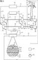
Eine Anlage zur Speicherung thermischer Energie gemäß
In
Weiterhin ist in
Der Aufbau des Niedertemperatur-Wärmespeichers
Der Kältespeicher
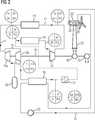
In
Anhand der Anlage gemäß den
In der Modellrechnung gelangt das Arbeitsgas mit 1 bar und 20°C in den (vorher aufgeladenen) Niedertemperatur-Wärmespeicher und verlässt diesen mit einer Temperatur von 80°C. Durch Komprimierung mittels der als Verdichter arbeitenden ersten Fluidenergie-Maschine
- T2
- die Temperatur am Verdichterausgang,
- T1
- die Temperatur am Verdichtereingang,
- ηc
- der isentropische Wirkungsgrad des Kompressors,
- π
- das Druckverhältnis (hier 15:1) und
- K
- die Kompressibilität ist, die
bei Luft 1,4 beträgt.
- T2
- the temperature at the compressor outlet,
- T1
- the temperature at the compressor inlet,
- ηc
- the isentropic efficiency of the compressor,
- π
- the pressure ratio (here 15: 1) and
- K
- the compressibility is 1.4 with air.
Der isentropische Wirkungsgrad ηc kann einem Kompressor mit 0,85 vorausgesetzt werden.The isentropic efficiency ηc can be assumed to be a compressor with 0.85.
Das erhitzte Arbeitsgas durchläuft nun den Wärmespeicher
In den Teil der Leitung
Im weiteren Verlauf entzieht das entspannte und daher abgekühlte Arbeitsgas dem Kältespeicher
Für die Kühlung ist in
Mittels
Das Arbeitsgas wird durch den Kältespeicher
Um diese Restwärme ebenfalls ausnutzen zu können, wird das Arbeitsgas anschließend durch den Niedertemperatur-Wärmespeicher geleitet und kühlt sich dadurch noch auf 130°C ab. Diese Wärme muss gespeichert werden, um in einem nachfolgenden Ladeprozess des Wärmespeichers
ZITATE ENTHALTEN IN DER BESCHREIBUNG QUOTES INCLUDE IN THE DESCRIPTION
Diese Liste der vom Anmelder aufgeführten Dokumente wurde automatisiert erzeugt und ist ausschließlich zur besseren Information des Lesers aufgenommen. Die Liste ist nicht Bestandteil der deutschen Patent- bzw. Gebrauchsmusteranmeldung. Das DPMA übernimmt keinerlei Haftung für etwaige Fehler oder Auslassungen.This list of the documents listed by the applicant has been generated automatically and is included solely for the better information of the reader. The list is not part of the German patent or utility model application. The DPMA assumes no liability for any errors or omissions.
Zitierte PatentliteraturCited patent literature
- US 2010/0257862 A1[0005]US 2010/0257862 A1[0005]
- US 5436508[0005]US 5436508[0005]
Claims (9)
Translated fromGermanPriority Applications (5)
| Application Number | Priority Date | Filing Date | Title |
|---|---|---|---|
| DE102012206296ADE102012206296A1 (en) | 2012-04-17 | 2012-04-17 | Plant for storage and delivery of thermal energy and method of operation thereof |
| PCT/EP2013/056735WO2013156292A1 (en) | 2012-04-17 | 2013-03-28 | System for storing and outputting thermal energy and method for operating said system |
| CN201380025845.XACN104302875A (en) | 2012-04-17 | 2013-03-28 | Device for storing and releasing heat energy and method of operation thereof |
| US14/394,141US20150059342A1 (en) | 2012-04-17 | 2013-03-28 | System for storing and outputting thermal energy and method for operating said system |
| EP13718802.5AEP2825735A1 (en) | 2012-04-17 | 2013-03-28 | System for storing and outputting thermal energy and method for operating said system |
Applications Claiming Priority (1)
| Application Number | Priority Date | Filing Date | Title |
|---|---|---|---|
| DE102012206296ADE102012206296A1 (en) | 2012-04-17 | 2012-04-17 | Plant for storage and delivery of thermal energy and method of operation thereof |
Publications (1)
| Publication Number | Publication Date |
|---|---|
| DE102012206296A1true DE102012206296A1 (en) | 2013-10-17 |
Family
ID=48190472
Family Applications (1)
| Application Number | Title | Priority Date | Filing Date |
|---|---|---|---|
| DE102012206296AWithdrawnDE102012206296A1 (en) | 2012-04-17 | 2012-04-17 | Plant for storage and delivery of thermal energy and method of operation thereof |
Country Status (5)
| Country | Link |
|---|---|
| US (1) | US20150059342A1 (en) |
| EP (1) | EP2825735A1 (en) |
| CN (1) | CN104302875A (en) |
| DE (1) | DE102012206296A1 (en) |
| WO (1) | WO2013156292A1 (en) |
Cited By (5)
| Publication number | Priority date | Publication date | Assignee | Title |
|---|---|---|---|---|
| WO2015131940A1 (en)* | 2014-03-05 | 2015-09-11 | Siemens Aktiengesellschaft | High-temperature energy storage system and operating method therefor |
| DE102017220977A1 (en)* | 2017-11-23 | 2019-05-23 | Siemens Aktiengesellschaft | Power plant with cooling system, method for operating such a power plant, method for modifying a power plant |
| CN112727603A (en)* | 2020-12-09 | 2021-04-30 | 华电电力科学研究院有限公司 | Combined power generation method applied to land desert simple cycle gas turbine power generation and thermoelectric power generation |
| DE102020110560A1 (en) | 2020-04-17 | 2021-10-21 | Deutsches Zentrum für Luft- und Raumfahrt e.V. | Method for operating a thermal potential storage system, thermal potential storage system, control program and computer-readable medium |
| DE102023123335A1 (en)* | 2023-08-30 | 2025-03-06 | Deutsches Zentrum für Luft- und Raumfahrt e.V. | heat storage system, especially cryogenic heat storage system |
Families Citing this family (11)
| Publication number | Priority date | Publication date | Assignee | Title |
|---|---|---|---|---|
| US9695748B2 (en) | 2015-04-10 | 2017-07-04 | Sten Kreuger | Energy storage and retrieval systems |
| US10323866B1 (en)* | 2016-09-27 | 2019-06-18 | Jacob Klein | Efficiency heat pump system |
| EP4165309B1 (en) | 2020-06-10 | 2024-10-02 | General Electric Renovables España, S.L. | Multisiphon passive cooling system with liquid bridge |
| CN112031884A (en)* | 2020-08-21 | 2020-12-04 | 上海交通大学 | Heat pump type electricity storage system based on Brayton cycle |
| CN112302750B (en)* | 2020-10-25 | 2022-06-21 | 上海交通大学 | Heat pump type energy storage and combined cooling heating and power system based on Brayton cycle |
| CN113048010B (en)* | 2021-03-25 | 2022-03-22 | 南方电网电力科技股份有限公司 | Control method of superconducting fan |
| CN113054797B (en)* | 2021-03-25 | 2022-04-19 | 南方电网电力科技股份有限公司 | Superconducting fan control method and device |
| CN113465226A (en)* | 2021-07-16 | 2021-10-01 | 中国科学院上海应用物理研究所 | Heat pump type energy storage power supply method and device |
| DK181199B1 (en)* | 2021-09-20 | 2023-04-25 | Stiesdal Storage As | A thermal energy storage system with environmental air exchange and a method of its operation |
| US12037990B2 (en) | 2022-09-08 | 2024-07-16 | Sten Kreuger | Energy storage and retrieval systems and methods |
| US12241691B1 (en) | 2024-05-03 | 2025-03-04 | Sten Kreuger | Energy storage and retrieval systems and methods |
Citations (8)
| Publication number | Priority date | Publication date | Assignee | Title |
|---|---|---|---|---|
| US5436508A (en) | 1991-02-12 | 1995-07-25 | Anna-Margrethe Sorensen | Wind-powered energy production and storing system |
| JPH1089788A (en)* | 1996-09-10 | 1998-04-10 | Nippon Sanso Kk | Method and apparatus for cooling object to be cooled |
| US20070028636A1 (en)* | 2005-07-26 | 2007-02-08 | Royal John H | Cryogenic refrigeration system for superconducting devices |
| US20070074533A1 (en)* | 2005-08-24 | 2007-04-05 | Purdue Research Foundation | Thermodynamic systems operating with near-isothermal compression and expansion cycles |
| JP2008249254A (en)* | 2007-03-30 | 2008-10-16 | Mitsubishi Heavy Ind Ltd | Refrigerating machine, and operating method and manufacturing method of refrigerating machine |
| US20100257862A1 (en) | 2007-10-03 | 2010-10-14 | Isentropic Limited | Energy Storage |
| US20100301614A1 (en)* | 2007-05-11 | 2010-12-02 | Saipem S.A | Installation and Method for Storing and Returning Electrical Energy |
| EP2532843A1 (en)* | 2011-06-09 | 2012-12-12 | ABB Research Ltd. | Thermoelectric energy storage system with an evaporative ice storage arrangement and method for storing thermoelectric energy |
Family Cites Families (9)
| Publication number | Priority date | Publication date | Assignee | Title |
|---|---|---|---|---|
| US4394814A (en)* | 1981-04-01 | 1983-07-26 | Wardman John C | Energy generation system |
| US7263845B2 (en)* | 2004-09-29 | 2007-09-04 | The Boc Group, Inc. | Backup cryogenic refrigeration system |
| DE102005013012A1 (en)* | 2005-03-21 | 2006-09-28 | ZAE Bayern Bayerisches Zentrum für angewandte Energieforschung e.V. | Latent heat storage for efficient cooling and heating systems |
| WO2007029680A1 (en)* | 2005-09-05 | 2007-03-15 | The Tokyo Electric Power Company, Incorporated | Vapor generation system |
| US20090224550A1 (en)* | 2008-03-06 | 2009-09-10 | General Electric Company | Systems involving superconducting direct drive generators for wind power applications |
| US20090230690A1 (en)* | 2008-03-13 | 2009-09-17 | General Electric Company | Systems involving superconducting homopolar alternators for wind power applications |
| CN102859118A (en)* | 2010-03-01 | 2013-01-02 | 布莱特能源存储科技有限责任公司 | Rotary compressor-expander systems and associated methods of use and manufacture |
| CN102971599A (en)* | 2010-07-12 | 2013-03-13 | 西门子公司 | Storage and recovery of thermal energy based on counter current principle of heat transfer medium transportation |
| JP4950367B1 (en)* | 2011-08-10 | 2012-06-13 | 三菱重工業株式会社 | Renewable energy generator |
- 2012
- 2012-04-17DEDE102012206296Apatent/DE102012206296A1/ennot_activeWithdrawn
- 2013
- 2013-03-28WOPCT/EP2013/056735patent/WO2013156292A1/enactiveApplication Filing
- 2013-03-28USUS14/394,141patent/US20150059342A1/ennot_activeAbandoned
- 2013-03-28EPEP13718802.5Apatent/EP2825735A1/ennot_activeWithdrawn
- 2013-03-28CNCN201380025845.XApatent/CN104302875A/enactivePending
Patent Citations (8)
| Publication number | Priority date | Publication date | Assignee | Title |
|---|---|---|---|---|
| US5436508A (en) | 1991-02-12 | 1995-07-25 | Anna-Margrethe Sorensen | Wind-powered energy production and storing system |
| JPH1089788A (en)* | 1996-09-10 | 1998-04-10 | Nippon Sanso Kk | Method and apparatus for cooling object to be cooled |
| US20070028636A1 (en)* | 2005-07-26 | 2007-02-08 | Royal John H | Cryogenic refrigeration system for superconducting devices |
| US20070074533A1 (en)* | 2005-08-24 | 2007-04-05 | Purdue Research Foundation | Thermodynamic systems operating with near-isothermal compression and expansion cycles |
| JP2008249254A (en)* | 2007-03-30 | 2008-10-16 | Mitsubishi Heavy Ind Ltd | Refrigerating machine, and operating method and manufacturing method of refrigerating machine |
| US20100301614A1 (en)* | 2007-05-11 | 2010-12-02 | Saipem S.A | Installation and Method for Storing and Returning Electrical Energy |
| US20100257862A1 (en) | 2007-10-03 | 2010-10-14 | Isentropic Limited | Energy Storage |
| EP2532843A1 (en)* | 2011-06-09 | 2012-12-12 | ABB Research Ltd. | Thermoelectric energy storage system with an evaporative ice storage arrangement and method for storing thermoelectric energy |
Non-Patent Citations (2)
| Title |
|---|
| Maschinenübersetzung der JP 2008 - 249 254 A |
| Maschinenübersetzung der JP H10 - 89 788 A |
Cited By (6)
| Publication number | Priority date | Publication date | Assignee | Title |
|---|---|---|---|---|
| WO2015131940A1 (en)* | 2014-03-05 | 2015-09-11 | Siemens Aktiengesellschaft | High-temperature energy storage system and operating method therefor |
| DE102017220977A1 (en)* | 2017-11-23 | 2019-05-23 | Siemens Aktiengesellschaft | Power plant with cooling system, method for operating such a power plant, method for modifying a power plant |
| US11637480B2 (en) | 2017-11-23 | 2023-04-25 | Siemens Energy Global GmbH & Co. KG | Power plant having a cooling system, method for operating such a power plant, method for modifying a power plant |
| DE102020110560A1 (en) | 2020-04-17 | 2021-10-21 | Deutsches Zentrum für Luft- und Raumfahrt e.V. | Method for operating a thermal potential storage system, thermal potential storage system, control program and computer-readable medium |
| CN112727603A (en)* | 2020-12-09 | 2021-04-30 | 华电电力科学研究院有限公司 | Combined power generation method applied to land desert simple cycle gas turbine power generation and thermoelectric power generation |
| DE102023123335A1 (en)* | 2023-08-30 | 2025-03-06 | Deutsches Zentrum für Luft- und Raumfahrt e.V. | heat storage system, especially cryogenic heat storage system |
Also Published As
| Publication number | Publication date |
|---|---|
| CN104302875A (en) | 2015-01-21 |
| WO2013156292A1 (en) | 2013-10-24 |
| US20150059342A1 (en) | 2015-03-05 |
| EP2825735A1 (en) | 2015-01-21 |
Similar Documents
| Publication | Publication Date | Title |
|---|---|---|
| DE102012206296A1 (en) | Plant for storage and delivery of thermal energy and method of operation thereof | |
| EP2574739A1 (en) | Assembly for storing thermal energy and method for its operation | |
| EP2748434B1 (en) | Assembly for storing thermal energy | |
| EP2986825B1 (en) | Energy storage arrangement for increasing the flexibility of power plants | |
| EP2450549A2 (en) | Compression heat-storage power plant or energy storage method for temporarily storing energy in the form of pressure energy in a compressible medium in the form of heat energy | |
| EP2823156B1 (en) | System for storing and outputting thermal energy | |
| DE102019127431B4 (en) | Thermal power storage with fixed bed heat storage and fixed bed cold storage and method for operating a thermal power storage | |
| EP2574756B1 (en) | Method for operating an adiabatic compressed air storage power plant and adiabatic compressed air storage power plant | |
| WO2010054844A2 (en) | Method for operating a wind turbine and wind turbine | |
| EP2825737A1 (en) | System for storing and outputting thermal energy having a heat accumulator and a cold accumulator and method for the operation thereof | |
| WO2015086588A1 (en) | Steam accumulator comprising a latent heat accumulator and a steam thermocompressor | |
| EP2489840A1 (en) | Energy storage device and method for its operation | |
| DE102010033956A1 (en) | Compressed gas storage device has heat absorption or heat transfer device with heat storage tank, where compressed gas tank is arranged within heat storage tank | |
| EP2859196B1 (en) | Energy transformation system | |
| DE102013008445B4 (en) | thermal storage power plant | |
| EP2574738A1 (en) | Assembly for storing thermal energy | |
| DE102016119245A1 (en) | Pressure storage device and storage method | |
| DE102021102231A1 (en) | Electrical energy storage system and method for storing and withdrawing electrical energy and computer program | |
| DE102015002926A1 (en) | Compressed air energy storage system with spindle machine | |
| WO2004017494A1 (en) | Dynamoelectric generator | |
| WO2014195075A1 (en) | Accumulator system coupled to gas turbines for intake fluid preheating | |
| DE102011115160A1 (en) | Fuel cell system mounted in vehicle, has expansion device that releases fuel from compressed gas storage portion under provision of electric power and comprises bungee cord which is provided with movable piston in free piston type | |
| EP2808502A1 (en) | Installation for the storage of energy in a liquefied process gas | |
| EP3775744A1 (en) | Method and device for compressing a gas | |
| DE102019000476A1 (en) | Building thermal power plant |
Legal Events
| Date | Code | Title | Description |
|---|---|---|---|
| R163 | Identified publications notified | ||
| R079 | Amendment of ipc main class | Free format text:PREVIOUS MAIN CLASS: F02C0006140000 Ipc:F25B0029000000 | |
| R119 | Application deemed withdrawn, or ip right lapsed, due to non-payment of renewal fee |