DE102012205490A1 - connecting element - Google Patents
connecting elementDownload PDFInfo
- Publication number
- DE102012205490A1 DE102012205490A1DE102012205490ADE102012205490ADE102012205490A1DE 102012205490 A1DE102012205490 A1DE 102012205490A1DE 102012205490 ADE102012205490 ADE 102012205490ADE 102012205490 ADE102012205490 ADE 102012205490ADE 102012205490 A1DE102012205490 A1DE 102012205490A1
- Authority
- DE
- Germany
- Prior art keywords
- receiving space
- connection
- connecting element
- valve element
- valve
- Prior art date
- Legal status (The legal status is an assumption and is not a legal conclusion. Google has not performed a legal analysis and makes no representation as to the accuracy of the status listed.)
- Withdrawn
Links
- 239000012530fluidSubstances0.000claimsabstractdescription35
- 238000004146energy storageMethods0.000abstractdescription5
- 239000007788liquidSubstances0.000description7
- 239000003814drugSubstances0.000description4
- 230000002093peripheral effectEffects0.000description4
- 229920002379silicone rubberPolymers0.000description4
- 238000003860storageMethods0.000description4
- 239000000463materialSubstances0.000description3
- KAKZBPTYRLMSJV-UHFFFAOYSA-NButadieneChemical compoundC=CC=CKAKZBPTYRLMSJV-UHFFFAOYSA-N0.000description2
- 239000004944Liquid Silicone RubberSubstances0.000description2
- 239000004698PolyethyleneSubstances0.000description2
- 239000004743PolypropyleneSubstances0.000description2
- PPBRXRYQALVLMV-UHFFFAOYSA-NStyreneChemical compoundC=CC1=CC=CC=C1PPBRXRYQALVLMV-UHFFFAOYSA-N0.000description2
- 238000004026adhesive bondingMethods0.000description2
- 238000004132cross linkingMethods0.000description2
- 229940079593drugDrugs0.000description2
- 230000000694effectsEffects0.000description2
- 239000013536elastomeric materialSubstances0.000description2
- 229920000573polyethylenePolymers0.000description2
- -1polypropylenePolymers0.000description2
- 229920001155polypropylenePolymers0.000description2
- 238000003825pressingMethods0.000description2
- 239000004945silicone rubberSubstances0.000description2
- NLHHRLWOUZZQLW-UHFFFAOYSA-NAcrylonitrileChemical compoundC=CC#NNLHHRLWOUZZQLW-UHFFFAOYSA-N0.000description1
- 241001631457CannulaSpecies0.000description1
- 238000011109contaminationMethods0.000description1
- 230000001627detrimental effectEffects0.000description1
- 239000013013elastic materialSubstances0.000description1
- 230000002349favourable effectEffects0.000description1
- 238000007731hot pressingMethods0.000description1
- 239000003978infusion fluidSubstances0.000description1
- 239000006193liquid solutionSubstances0.000description1
- 238000004519manufacturing processMethods0.000description1
- 239000004417polycarbonateSubstances0.000description1
- 229920000515polycarbonatePolymers0.000description1
- 239000000243solutionSubstances0.000description1
- 229920001169thermoplasticPolymers0.000description1
- 239000004416thermosoftening plasticSubstances0.000description1
- 238000003466weldingMethods0.000description1
Images
Classifications
- F—MECHANICAL ENGINEERING; LIGHTING; HEATING; WEAPONS; BLASTING
- F16—ENGINEERING ELEMENTS AND UNITS; GENERAL MEASURES FOR PRODUCING AND MAINTAINING EFFECTIVE FUNCTIONING OF MACHINES OR INSTALLATIONS; THERMAL INSULATION IN GENERAL
- F16L—PIPES; JOINTS OR FITTINGS FOR PIPES; SUPPORTS FOR PIPES, CABLES OR PROTECTIVE TUBING; MEANS FOR THERMAL INSULATION IN GENERAL
- F16L37/00—Couplings of the quick-acting type
- F16L37/28—Couplings of the quick-acting type with fluid cut-off means
- F16L37/30—Couplings of the quick-acting type with fluid cut-off means with fluid cut-off means in each of two pipe-end fittings
- A—HUMAN NECESSITIES
- A61—MEDICAL OR VETERINARY SCIENCE; HYGIENE
- A61M—DEVICES FOR INTRODUCING MEDIA INTO, OR ONTO, THE BODY; DEVICES FOR TRANSDUCING BODY MEDIA OR FOR TAKING MEDIA FROM THE BODY; DEVICES FOR PRODUCING OR ENDING SLEEP OR STUPOR
- A61M39/00—Tubes, tube connectors, tube couplings, valves, access sites or the like, specially adapted for medical use
- A61M39/10—Tube connectors; Tube couplings
- A—HUMAN NECESSITIES
- A61—MEDICAL OR VETERINARY SCIENCE; HYGIENE
- A61M—DEVICES FOR INTRODUCING MEDIA INTO, OR ONTO, THE BODY; DEVICES FOR TRANSDUCING BODY MEDIA OR FOR TAKING MEDIA FROM THE BODY; DEVICES FOR PRODUCING OR ENDING SLEEP OR STUPOR
- A61M39/00—Tubes, tube connectors, tube couplings, valves, access sites or the like, specially adapted for medical use
- A61M39/22—Valves or arrangement of valves
- A61M39/26—Valves closing automatically on disconnecting the line and opening on reconnection thereof
- F—MECHANICAL ENGINEERING; LIGHTING; HEATING; WEAPONS; BLASTING
- F16—ENGINEERING ELEMENTS AND UNITS; GENERAL MEASURES FOR PRODUCING AND MAINTAINING EFFECTIVE FUNCTIONING OF MACHINES OR INSTALLATIONS; THERMAL INSULATION IN GENERAL
- F16F—SPRINGS; SHOCK-ABSORBERS; MEANS FOR DAMPING VIBRATION
- F16F1/00—Springs
- F16F1/02—Springs made of steel or other material having low internal friction; Wound, torsion, leaf, cup, ring or the like springs, the material of the spring not being relevant
- F16F1/18—Leaf springs
- A—HUMAN NECESSITIES
- A61—MEDICAL OR VETERINARY SCIENCE; HYGIENE
- A61M—DEVICES FOR INTRODUCING MEDIA INTO, OR ONTO, THE BODY; DEVICES FOR TRANSDUCING BODY MEDIA OR FOR TAKING MEDIA FROM THE BODY; DEVICES FOR PRODUCING OR ENDING SLEEP OR STUPOR
- A61M39/00—Tubes, tube connectors, tube couplings, valves, access sites or the like, specially adapted for medical use
- A61M39/10—Tube connectors; Tube couplings
- A61M2039/1077—Adapters, e.g. couplings adapting a connector to one or several other connectors
- A—HUMAN NECESSITIES
- A61—MEDICAL OR VETERINARY SCIENCE; HYGIENE
- A61M—DEVICES FOR INTRODUCING MEDIA INTO, OR ONTO, THE BODY; DEVICES FOR TRANSDUCING BODY MEDIA OR FOR TAKING MEDIA FROM THE BODY; DEVICES FOR PRODUCING OR ENDING SLEEP OR STUPOR
- A61M39/00—Tubes, tube connectors, tube couplings, valves, access sites or the like, specially adapted for medical use
- A61M39/22—Valves or arrangement of valves
- A61M39/26—Valves closing automatically on disconnecting the line and opening on reconnection thereof
- A61M2039/261—Valves closing automatically on disconnecting the line and opening on reconnection thereof where the fluid space within the valve is increasing upon disconnection
- A—HUMAN NECESSITIES
- A61—MEDICAL OR VETERINARY SCIENCE; HYGIENE
- A61M—DEVICES FOR INTRODUCING MEDIA INTO, OR ONTO, THE BODY; DEVICES FOR TRANSDUCING BODY MEDIA OR FOR TAKING MEDIA FROM THE BODY; DEVICES FOR PRODUCING OR ENDING SLEEP OR STUPOR
- A61M39/00—Tubes, tube connectors, tube couplings, valves, access sites or the like, specially adapted for medical use
- A61M39/22—Valves or arrangement of valves
- A61M39/26—Valves closing automatically on disconnecting the line and opening on reconnection thereof
- A61M2039/267—Valves closing automatically on disconnecting the line and opening on reconnection thereof having a sealing sleeve around a tubular or solid stem portion of the connector
- Y—GENERAL TAGGING OF NEW TECHNOLOGICAL DEVELOPMENTS; GENERAL TAGGING OF CROSS-SECTIONAL TECHNOLOGIES SPANNING OVER SEVERAL SECTIONS OF THE IPC; TECHNICAL SUBJECTS COVERED BY FORMER USPC CROSS-REFERENCE ART COLLECTIONS [XRACs] AND DIGESTS
- Y10—TECHNICAL SUBJECTS COVERED BY FORMER USPC
- Y10T—TECHNICAL SUBJECTS COVERED BY FORMER US CLASSIFICATION
- Y10T137/00—Fluid handling
- Y10T137/8593—Systems
- Y10T137/87917—Flow path with serial valves and/or closures
- Y10T137/87925—Separable flow path section, valve or closure in each
Landscapes
- Health & Medical Sciences (AREA)
- Engineering & Computer Science (AREA)
- Heart & Thoracic Surgery (AREA)
- General Engineering & Computer Science (AREA)
- Anesthesiology (AREA)
- Pulmonology (AREA)
- Biomedical Technology (AREA)
- Hematology (AREA)
- Life Sciences & Earth Sciences (AREA)
- Animal Behavior & Ethology (AREA)
- General Health & Medical Sciences (AREA)
- Public Health (AREA)
- Veterinary Medicine (AREA)
- Mechanical Engineering (AREA)
- Infusion, Injection, And Reservoir Apparatuses (AREA)
Abstract
Translated fromGermanDescription
Translated fromGermanTechnisches GebietTechnical area
Die Erfindung betrifft ein Verbindungselement, insbesondere zum Verbinden von Gefäßen und zur Erzeugung einer Fluidverbindung zwischen an dem Verbindungselement angeschlossenen Gefäßen bzw. Elementen.The invention relates to a connecting element, in particular for connecting vessels and for producing a fluid connection between connected to the connecting element vessels or elements.
Stand der TechnikState of the art
Insbesondere im medizinischen Anwendungsbereich ist es im Stand der Technik bekannt, dass flüssige Lösungen oder Medikamente mittels Spritzen aus einem Vorratsgefäß aufgenommen werden und Patienten verabreicht werden. Dazu ist bekannt, dass mit der Spritze die Flüssigkeit direkt über die Kanüle der Spritze aufgenommen wird und anschließend direkt dem Patienten verabreicht wird.In the medical field in particular, it is known in the prior art that liquid solutions or medicaments are taken up by syringes from a storage container and administered to patients. It is known that with the syringe, the liquid is absorbed directly via the cannula of the syringe and then administered directly to the patient.
Auch ist es bekannt, dass auf das Vorratsgefäß ein Verbindungselement aufgesetzt wird, woran dann die Spritze angebracht werden kann, um die Flüssigkeit aus dem Vorratsgefäß auf die Spritze aufzuziehen. Zieht man die Spritze anschließend wieder davon ab, so kann dennoch Flüssigkeit aus der Spritze auslaufen, was insbesondere bei sehr teuren Medikamenten sehr nachteilig ist. Auch ist damit eine Verschmutzung möglich weil austretende Medikamente oder Flüssigkeiten verloren werden können, was im medizinischen Bereich oder im Pflegebereich als nachteilig angesehen ist.It is also known that a connecting element is placed on the storage vessel, to which then the syringe can be attached to draw the liquid from the storage vessel to the syringe. If you then withdraw the syringe from it, so liquid may leak out of the syringe, which is very disadvantageous especially for very expensive drugs. Also so that contamination is possible because escaping drugs or liquids can be lost, which is considered to be detrimental in the medical field or in the care sector.
Auch ist es bekannt, dass insbesondere Infusionslösungen mittels Schlauchleitungen mit einer Kanüle verbunden werden können, wobei auch in solche Schlauchleitungen oder Kanülen Medikamente zu dosiert werden können. Dies erfolgt dann über ein Verbindungselement, das den gleichen Nachteilen unterliegt, wie bereits oben beschrieben.It is also known that, in particular, infusion solutions can be connected by means of tubing to a cannula, whereby medicaments can also be metered into such tubing or cannulas. This is then done via a connecting element, which is subject to the same disadvantages as already described above.
Darstellung der Erfindung, Aufgabe, Lösung, VorteilePresentation of the invention, object, solution, advantages
Es ist die Aufgabe der Erfindung, ein Verbindungselement zu schaffen, welches eine sichere Verbindung erlaubt und dennoch bei einem Nichtverbinden einen sicheren und dichten Abschluss des damit verbundenen Gefäßes erlaubt.It is the object of the invention to provide a connecting element, which allows a secure connection and yet allows a non-connecting a secure and tight closure of the associated vessel.
Dies wird erreicht mit den Merkmalen von Anspruch 1.This is achieved with the features of
Ein vorteilhaftes Ausführungsbeispiel der Erfindung betrifft ein Verbindungselement mit einem Gehäuse mit einem ersten Aufnahmeraum mit einem ersten Anschlusselement und einem darin angeordneten ersten verlagerbaren Ventilelement und mit einem zweiten Aufnahmeraum mit einem zweiten Anschlusselement mit einem darin angeordneten zweiten verlagerbaren Ventilelement, der erste und der zweite Aufnahmeraum sind miteinander fluidverbunden, wobei das erste Ventilelement entgegen der Kraft eines ersten Kraftspeichers verlagerbar ist und das zweite Ventilelement entgegen eines zweiten Kraftspeichers verlagerbar ist, wobei das erste Ventilelement zwischen zwei Positionen verlagerbar ist, wobei in der ersten Position eine Fluidverbindung zwischen dem ersten Aufnahmeraum und dem ersten Anschlusselement durch das erste Ventilelement unterbrochen ist und in der zweiten Position eine Fluidverbindung zwischen dem ersten Aufnahmeraum und dem ersten Anschlusselement durch das erste Ventilelement geöffnet ist und wobei das zweite Ventilelement zwischen zwei Positionen verlagerbar ist, wobei in der ersten Position eine Fluidverbindung zwischen dem zweiten Aufnahmeraum und dem zweiten Anschlusselement durch das zweite Ventilelement unterbrochen ist und in der zweiten Position eine Fluidverbindung zwischen dem zweiten Aufnahmeraum und dem zweiten Anschlusselement durch das zweite Ventilelement geöffnet ist.An advantageous embodiment of the invention relates to a connecting element with a housing having a first receiving space with a first connection element and a first displaceable valve element arranged therein and with a second receiving space with a second connection element with a second displaceable valve element disposed therein, the first and the second receiving space fluidly connected to one another, wherein the first valve element is displaceable against the force of a first energy accumulator and the second valve element is displaceable against a second energy accumulator, wherein the first valve element is displaceable between two positions, wherein in the first position, a fluid connection between the first receiving space and the first Connection element is interrupted by the first valve element and in the second position, a fluid connection between the first receiving space and the first connection element by the first valve element geöff is net and wherein the second valve element is displaceable between two positions, wherein in the first position, a fluid connection between the second receiving space and the second connection element is interrupted by the second valve element and in the second position, a fluid connection between the second receiving space and the second connection element the second valve element is open.
Dies bewirkt, dass der erste Aufnahmeraum mit einem an das erste Anschlusselement anschließbaren Gefäß verbindbar ist und der zweite Aufnahmeraum mit einem an das zweite Anschlusselement anschließbaren Gefäß verbindbar ist, wobei im Falle eines Nichtanschließens an dem jeweiligen Anschlusselement, das Anschlusselement entsprechend mittels des diesbezüglich angeordneten Ventilelements verschlossen ist. Dadurch wird erreicht, dass das Verbindungselement dann einen Fluiddurchgang erzeugt, wenn an beiden Anschlusselementen ein Gefäß angeschlossen ist. Ist nur ein Gefäß angeschlossen, so ist das Anschlusselement verschlossen, an welchem kein Gefäß angeschlossen ist. Dies bewirkt, dass das Gefäß in diesem Betriebszustand auch mit angeordnetem Verbindungselement verschlossen ist.This has the effect that the first receiving space can be connected to a vessel which can be connected to the first connecting element and the second receiving space can be connected to a vessel which can be connected to the second connecting element, wherein in the case of non-connection to the respective connecting element, the connecting element accordingly by means of the valve element arranged in this respect is closed. This ensures that the connecting element then generates a fluid passage when a vessel is connected to both connecting elements. If only one vessel is connected, the connection element is closed, to which no vessel is connected. This causes the vessel is closed in this operating state with arranged connecting element.
Als Gefäß kann hier eine Spritze, eine Flasche, ein Schlauch, ein Beutel oder ähnliches verstanden werden, in welchem eine Flüssigkeit aufgenommen sein kann.As a vessel can here be understood a syringe, a bottle, a hose, a bag or the like, in which a liquid can be received.
Dabei ist es bei einem Ausführungsbeispiel vorteilhaft, wenn das Gehäuse zumindest zweiteilig ausgebildet ist. Dabei sind die beiden Teile vorteilhaft miteinander verpresst, formschlüssig verbunden, verclipst, verschweißt, verklebt oder anderweitig verbunden.It is advantageous in one embodiment, when the housing is formed at least in two parts. The two parts are advantageously pressed together, positively connected, clipped, welded, glued or otherwise connected.
Bei einem Verpressen kann eine Verbindung ohne weitere Elemente kostengünstig erfolgen. Dabei stört auch kein Fremdmaterial die später durch das Verbindungselement fließenden Flüssigkeiten. Auch sorgt ein Kleben für eine zuverlässige dichte Verbindung.When pressing a connection without additional elements can be done inexpensively. In this case, no foreign material disturbs the later flowing through the connecting element liquids. Gluing also ensures a reliable tight connection.
Weiterhin ist es zweckmäßig, wenn der erste Aufnahmeraum von einem ersten und einem zweiten Gehäuseteil gebildet wird und der zweite Aufnahmeraum von dem zweiten Gehäuseteil gebildet wird. Dabei werden die beiden Gehäuseteile so miteinander verbunden, dass der Aufnahmeraum zwischen den beide Gehäusehälften entsteht. Dies kann vorteilhaft so erfolgen, dass die beiden Gehäuseteile einen Boden mit einer umlaufenden Wand aufweisen, die so ineinander gefügt werden, dass die beiden umlaufenden Wände aneinander anliegen und die beiden Böden beanstandet voneinander angeordnet sind und so zwischen sich ein Volumen für die Aufnahme oder Durchströmung einer Flüssigkeit erzeugen. Furthermore, it is expedient if the first receiving space is formed by a first and a second housing part and the second receiving space is formed by the second housing part. In this case, the two housing parts are connected to each other so that the receiving space between the two housing halves is formed. This can advantageously be done so that the two housing parts have a bottom with a circumferential wall, which are joined together so that the two circumferential walls abut each other and the two floors are spaced apart from each other and so between them a volume for receiving or flow create a liquid.
Vorteilhaft ist es, wenn das erste Anschlusselement an dem ersten Gehäuseteil angeordnet oder ausgebildet ist und das zweite Anschlusselement an dem zweiten Gehäuseteil angeordnet oder ausgebildet ist. Dabei ist es besonders vorteilhaft, wenn die beiden Anschlusselemente sich gegenüber liegen, so dass eine im Wesentlichen lineare Durchströmung ergibt. Dadurch kann eine günstige Geometrie erreicht werden und der Druckabfall bleibt bei gerader Durchströmung auch gering, was die Betätigungskräfte beispielsweise bei dem Aufziehen einer Spritze reduziert bzw. gering hält.It is advantageous if the first connection element is arranged or formed on the first housing part and the second connection element is arranged or formed on the second housing part. It is particularly advantageous if the two connection elements are opposite, so that results in a substantially linear flow. As a result, a favorable geometry can be achieved and the pressure drop remains at straight flow also low, which reduces the operating forces, for example, when mounting a syringe or keeps low.
Erfindungsgemäß ist es vorteilhaft, wenn der erste Aufnahmeraum einen im Schnitt etwa kreisförmigen Querschnitt aufweist und von einer umlaufenden Wand begrenzt ist, wobei der Aufnahmeraum von zwei etwa ebenen Wandbereichen begrenzt wird, wobei das erste Anschlusselement an einer der beiden Wände angeordnet oder aufgenommen ist und in der anderen Wand eine Fluidverbindung zu dem zweiten Aufnahmeraum vorgesehen ist. Der Aufnahmeraum ist vorteilhaft somit etwa zylindrisch mit einer umlaufenden Umfangswand und zwei sich etwa gegenüberliegenden Wänden. Dabei ist es vorteilhaft, wenn die Umfangswand eine Zylinderwand ist, die sich gegen eine entsprechende Wand des anderen Gehäuseteils abstützen kann, um eine gute Abdichtung zu erreichen.According to the invention, it is advantageous if the first receiving space has an approximately circular cross-section and is bounded by a circumferential wall, wherein the receiving space is bounded by two approximately flat wall areas, wherein the first connecting element is arranged or accommodated on one of the two walls and in the other wall is provided a fluid connection to the second receiving space. The receiving space is thus advantageous approximately cylindrical with a peripheral peripheral wall and two approximately opposite walls. It is advantageous if the peripheral wall is a cylinder wall which can be supported against a corresponding wall of the other housing part in order to achieve a good seal.
Besonders vorteilhaft ist es, wenn das erste Anschlusselement ein hohlzylindrisches Element aufweist und das erste Ventilelement zumindest einen zylindrischen Bereich aufweist, welcher in dem hohlzylindrischen Element verlagerbar aufgenommen ist. Dabei ist es vorteilhaft, wenn das im Wesentlichen zylindrische Element aus einem elastischen Material gefertigt ist, so dass es sich an der Wand des hohlzylindrischen Elements anlegen und darf abdichten kann. Wird das Ventilelement durch Kraftbeaufschlagung verlagert, so wird eine Kante des zylindrischen Elements in oder über einen Bereich verschoben, in welchem beispielsweise eine Abweichung der hohlzylindrischen Kontur vorliegt oder eine Nut vorliegt, so dass eine Fluidverbindung zwischen dem Anschlusselement und dem Aufnahmeraum erzeugt wird.It is particularly advantageous if the first connection element has a hollow-cylindrical element and the first valve element has at least one cylindrical region which is received displaceably in the hollow-cylindrical element. It is advantageous if the substantially cylindrical element is made of an elastic material, so that it can rest on the wall of the hollow cylindrical element and may seal. If the valve element is displaced by application of force, then an edge of the cylindrical element is displaced into or over an area in which, for example, there is a deviation of the hollow cylindrical contour or there is a groove, so that a fluid connection is produced between the connection element and the receiving space.
Weiterhin ist es zweckmäßig, wenn das Ventilelement an dem zylindrischen Bereich abragende Federarme aufweist. Dabei kann der zylindrische Bereich an einer Seite Federarme aufweisen, vorteilhaft zumindest drei Federarme, die gleichmäßig zur Senkrechten abragen, wie beispielsweise die Kanten eines Tetraeders. Dabei ist es vorteilhaft, wenn die Federarme gleichmäßig verteilt abragen. Auch können mehr als drei Federarme abragen.Furthermore, it is expedient if the valve element has protruding spring arms on the cylindrical area. In this case, the cylindrical portion may have on one side spring arms, advantageously at least three spring arms, which project evenly to the vertical, such as the edges of a tetrahedron. It is advantageous if the spring arms protrude evenly distributed. Also, more than three spring arms can protrude.
Vorteilhaft ist es, wenn der zweite Aufnahmeraum einen Bereich mit im Schnitt kreisförmigen Querschnitt aufweist, der von einem umlaufenden Wand begrenzt ist, wobei der Aufnahmeraum von zwei etwa ebenen Wandbereichen begrenzt wird, wobei das zweite Anschlusselement an einer der beiden Wände angeordnet oder aufgenommen ist und in der anderen Wand eine Fluidverbindung zu dem ersten Aufnahmeraum vorgesehen ist. Die Wand zur Erzeugung einer Fluidverbindung zum ersten Aufnahmeraum wird dabei vorteilhaft durch das gleiche Element gebildet, welches auch die Wand des ersten Aufnahmeraums bildet, welche die Fluidverbindung mit dem zweiten Aufnahmeraum erzeugt. Dabei ist es vorteilhaft, wenn die jeweilige Wand sich an einem Element befindet und die jeweils gegenüberliegende Wand einer Platte, Scheibe oder ähnliches ist. Die Fluidverbindung wird dann vorteilhaft durch zumindest eine, vorteilhaft eine Mehrzahl von Öffnungen bewirkt.It is advantageous if the second receiving space has an area with a cross-sectionally circular cross section, which is bounded by a circumferential wall, wherein the receiving space is bounded by two approximately flat wall areas, wherein the second connection element is arranged or received on one of the two walls and in the other wall, a fluid connection is provided to the first receiving space. The wall for generating a fluid connection to the first receiving space is advantageously formed by the same element, which also forms the wall of the first receiving space, which creates the fluid connection with the second receiving space. It is advantageous if the respective wall is located on an element and the respective opposite wall of a plate, disc or the like. The fluid connection is then advantageously effected by at least one, advantageously a plurality of openings.
Weiterhin ist es vorteilhaft, wenn von der anderen Wand ein Dorn abragt, welcher in das zweite Anschlusselement eingreift. Der Dorn ist vorteilhaft ein flacher oder zylindrischer Steg, der in eine Hülse des zweiten Anschlusselements eingreift. Dabei hat der Dorn vorteilhaft an seinem Ende einen verdickten Bereich, an welchem sich die Hülse endseitig abstützt.Furthermore, it is advantageous if a mandrel protruding from the other wall, which engages in the second connection element. The mandrel is advantageously a flat or cylindrical web which engages in a sleeve of the second connection element. In this case, the mandrel has advantageously at its end a thickened region on which the sleeve is supported at the end.
Auch ist es vorteilhaft, wenn die eine Wand mit dem Anschlusselement als zweites Ventilelement entgegen der Kraft eines Kraftspeichers verlagerbar ist und dadurch eine Fluidverbindung zwischen dem Anschlusselement und dem in das Anschlusselement hineinragenden Dorn freigebbar ist.It is also advantageous if the one wall with the connecting element as a second valve element against the force of a force accumulator is displaced and thereby a fluid connection between the connecting element and the protruding into the connecting element mandrel is releasable.
Vorteilhaft ist es weiterhin, wenn der zweite Kraftspeicher ein elastisches Element ist, welches in dem zweiten Aufnahmeraum angeordnet ist.It is furthermore advantageous if the second energy store is an elastic element which is arranged in the second receiving space.
Dabei ist es zweckmäßig, wenn der zweite Kraftspeicher ein elastischer Ring ist, wie vorzugsweise ein elastischer Ovalring oder O-Ring.It is expedient if the second energy store is an elastic ring, such as preferably an elastic oval ring or O-ring.
Weitere vorteilhafte Ausgestaltungen sind durch die nachfolgende Figurenbeschreibung und durch die Unteransprüche beschrieben.Further advantageous embodiments are described by the following description of the figures and by the subclaims.
Kurze Beschreibung der Zeichnungen Brief description of the drawings
Nachstehend wird die Erfindung auf der Grundlage zumindest eines Ausführungsbeispiels anhand der Zeichnungen näher erläutert. Es zeigen:The invention will be explained in more detail on the basis of at least one embodiment with reference to the drawings. Show it:
Bevorzugte Ausführung der ErfindungPreferred embodiment of the invention
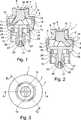
Die
Das Verbindungselement
Das erste Gehäuseteil
Das zweite Gehäuseteil
Wie in den
Alternativ kann auch die Wand
Zur Verbindung der beiden Gehäuseteile
Das Gehäuse bildet einen ersten Aufnahmeraum
Nach oben am Boden
Dies wird erreicht mit einem Ventilelement
Die Federarme
In den
Wird das zu verbindende Element wieder aus dem Anschlusselement
Im unteren Bereich des Verbindungselements
Als Ventilelement ist ein hülsenförmiges Element
Wird von unten ein zu verbindendes Element mit einem umlaufenden Kragen in den Bereich
Bevorzugt sind die elastischen Elemente
Das Element
Vorteilhaft kann auch sein, wenn zwischen dem Element
Alternativ zur Ausbildung des Kraftspeichers
Vorteilhaft könnte es auch sein, wenn das bislang als unsymmetrisch ausgebildete Element durch Vorsehung zweier identischer oder im Wesentlichen identischer Bauteile oder Bereiche symmetrisch gestaltet ist, so dass beispielsweise das Ventilelement
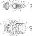
Die
Die
Wie zu erkennen ist, bilden die Gehäuseteile
In
Das Ventilelement
Claims (12)
Translated fromGermanPriority Applications (6)
| Application Number | Priority Date | Filing Date | Title |
|---|---|---|---|
| DE102012205490ADE102012205490A1 (en) | 2012-04-03 | 2012-04-03 | connecting element |
| EP13715183.3AEP2833959B1 (en) | 2012-04-03 | 2013-04-02 | Fluid connector |
| PCT/EP2013/056959WO2013150037A1 (en) | 2012-04-03 | 2013-04-02 | Fluid-connecting element |
| DE112013001925.6TDE112013001925A5 (en) | 2012-04-03 | 2013-04-02 | Fluid coupling device |
| US14/505,203US9903519B2 (en) | 2012-04-03 | 2014-10-02 | Fluid-connecting element |
| US15/868,477US10408372B2 (en) | 2012-04-03 | 2018-01-11 | Fluid-connecting element |
Applications Claiming Priority (1)
| Application Number | Priority Date | Filing Date | Title |
|---|---|---|---|
| DE102012205490ADE102012205490A1 (en) | 2012-04-03 | 2012-04-03 | connecting element |
Publications (1)
| Publication Number | Publication Date |
|---|---|
| DE102012205490A1true DE102012205490A1 (en) | 2013-10-10 |
Family
ID=48083143
Family Applications (2)
| Application Number | Title | Priority Date | Filing Date |
|---|---|---|---|
| DE102012205490AWithdrawnDE102012205490A1 (en) | 2012-04-03 | 2012-04-03 | connecting element |
| DE112013001925.6TPendingDE112013001925A5 (en) | 2012-04-03 | 2013-04-02 | Fluid coupling device |
Family Applications After (1)
| Application Number | Title | Priority Date | Filing Date |
|---|---|---|---|
| DE112013001925.6TPendingDE112013001925A5 (en) | 2012-04-03 | 2013-04-02 | Fluid coupling device |
Country Status (4)
| Country | Link |
|---|---|
| US (2) | US9903519B2 (en) |
| EP (1) | EP2833959B1 (en) |
| DE (2) | DE102012205490A1 (en) |
| WO (1) | WO2013150037A1 (en) |
Cited By (2)
| Publication number | Priority date | Publication date | Assignee | Title |
|---|---|---|---|---|
| DE102014221158A1 (en)* | 2014-10-17 | 2016-04-21 | B. Braun Melsungen Aktiengesellschaft | Multi-component injection-molded component and plastic injection-molded tool for producing such a multi-component injection-molded component |
| JPWO2015146142A1 (en)* | 2014-03-26 | 2017-04-13 | テルモ株式会社 | Connector and infusion set |
Families Citing this family (2)
| Publication number | Priority date | Publication date | Assignee | Title |
|---|---|---|---|---|
| MX384540B (en)* | 2016-01-19 | 2025-03-14 | Wilmarc Holdings Llc | CONNECTOR SYSTEM FOR RELEASEABLY CONNECTING FLUID CONDUITS |
| US20240075273A1 (en)* | 2022-09-07 | 2024-03-07 | Carefusion 303, Inc. | Needleless connector |
Citations (8)
| Publication number | Priority date | Publication date | Assignee | Title |
|---|---|---|---|---|
| US4763683A (en)* | 1987-09-21 | 1988-08-16 | Catlow, Inc. | Breakaway coupling for a coaxial fuel supply hose |
| US5890517A (en)* | 1997-11-04 | 1999-04-06 | Laible; Rodney | Vented quick disconnect coupling |
| DE69323893T2 (en)* | 1992-10-27 | 1999-11-11 | Colder Products Co., St. Paul | QUICK COUPLING WITH A VALVE ARRANGEMENT |
| US6024124A (en)* | 1995-01-06 | 2000-02-15 | Colder Products Company | Low spill high flow quick coupling valve assembly |
| US6050297A (en)* | 1998-11-17 | 2000-04-18 | Dresser Industries, Inc. | Breakaway hose coupling for fuel dispensers |
| US6302147B1 (en)* | 1999-04-08 | 2001-10-16 | Joseph Lorney Rose | Automatic dry release valve coupling |
| US6705591B2 (en)* | 2001-10-02 | 2004-03-16 | Colder Products Company | Poppet valve and method of making same |
| US7182313B2 (en)* | 2001-08-10 | 2007-02-27 | Cardinal Health 303, Inc. | Valved male luer |
Family Cites Families (17)
| Publication number | Priority date | Publication date | Assignee | Title |
|---|---|---|---|---|
| US4286636A (en)* | 1979-07-19 | 1981-09-01 | The Coca-Cola Company | Dip tube and valve with quick-disconnect coupling for a collapsible container |
| US4421296A (en)* | 1980-07-17 | 1983-12-20 | Medical Valve Corporation | Disposable plastic reciprocating valve |
| US4899786A (en)* | 1989-02-07 | 1990-02-13 | Gt Development Corporation | Breakaway fluid coupling |
| US5168897A (en)* | 1990-01-16 | 1992-12-08 | Ingersoll-Rand Company | Quick and dry coupling |
| US5163922A (en)* | 1991-04-29 | 1992-11-17 | Charles E. McElveen, Jr. | Dual-valved connector for intravenous systems |
| US5839715A (en)* | 1995-05-16 | 1998-11-24 | Alaris Medical Systems, Inc. | Medical adapter having needleless valve and sharpened cannula |
| WO1998011931A1 (en)* | 1996-09-19 | 1998-03-26 | Pall Corporation | Breathing filter |
| US6364869B1 (en)* | 2000-06-07 | 2002-04-02 | Creative Plastics Technology, Llc | Medical connector with swabbable stopper |
| US7600530B2 (en)* | 2004-08-09 | 2009-10-13 | Medegen, Inc. | Connector with check valve and method of use |
| DE202004014130U1 (en)* | 2004-09-11 | 2005-02-03 | Kaspers, Norbert | Luer-type tube connector for use in surgery, comprising specifically shaped basket valve |
| US7857284B2 (en)* | 2006-04-11 | 2010-12-28 | Nypro Inc. | Medical valve with movable member |
| ATE480471T1 (en)* | 2007-05-30 | 2010-09-15 | Eurokeg Bv | CLOSING VALVE AND CONTAINER WITH IT |
| US8454579B2 (en)* | 2009-03-25 | 2013-06-04 | Icu Medical, Inc. | Medical connector with automatic valves and volume regulator |
| JP5836939B2 (en)* | 2009-06-22 | 2015-12-24 | エヌピー メディカル インコーポレイテッド | Medical valve with improved back pressure seal |
| CA2789612A1 (en)* | 2010-02-11 | 2011-08-18 | Hollister Incorporated | Inflation cuff with transient-resistant over-pressure preventor |
| EP2550058B1 (en)* | 2010-05-06 | 2014-03-26 | ICU Medical, Inc. | Medical connector with closeable luer connector |
| CN103269744A (en)* | 2010-08-06 | 2013-08-28 | 诺信公司 | Shut-off valves for fluid line connectors |
- 2012
- 2012-04-03DEDE102012205490Apatent/DE102012205490A1/ennot_activeWithdrawn
- 2013
- 2013-04-02EPEP13715183.3Apatent/EP2833959B1/enactiveActive
- 2013-04-02WOPCT/EP2013/056959patent/WO2013150037A1/enactiveApplication Filing
- 2013-04-02DEDE112013001925.6Tpatent/DE112013001925A5/enactivePending
- 2014
- 2014-10-02USUS14/505,203patent/US9903519B2/enactiveActive
- 2018
- 2018-01-11USUS15/868,477patent/US10408372B2/enactiveActive
Patent Citations (8)
| Publication number | Priority date | Publication date | Assignee | Title |
|---|---|---|---|---|
| US4763683A (en)* | 1987-09-21 | 1988-08-16 | Catlow, Inc. | Breakaway coupling for a coaxial fuel supply hose |
| DE69323893T2 (en)* | 1992-10-27 | 1999-11-11 | Colder Products Co., St. Paul | QUICK COUPLING WITH A VALVE ARRANGEMENT |
| US6024124A (en)* | 1995-01-06 | 2000-02-15 | Colder Products Company | Low spill high flow quick coupling valve assembly |
| US5890517A (en)* | 1997-11-04 | 1999-04-06 | Laible; Rodney | Vented quick disconnect coupling |
| US6050297A (en)* | 1998-11-17 | 2000-04-18 | Dresser Industries, Inc. | Breakaway hose coupling for fuel dispensers |
| US6302147B1 (en)* | 1999-04-08 | 2001-10-16 | Joseph Lorney Rose | Automatic dry release valve coupling |
| US7182313B2 (en)* | 2001-08-10 | 2007-02-27 | Cardinal Health 303, Inc. | Valved male luer |
| US6705591B2 (en)* | 2001-10-02 | 2004-03-16 | Colder Products Company | Poppet valve and method of making same |
Cited By (4)
| Publication number | Priority date | Publication date | Assignee | Title |
|---|---|---|---|---|
| JPWO2015146142A1 (en)* | 2014-03-26 | 2017-04-13 | テルモ株式会社 | Connector and infusion set |
| EP3124071A4 (en)* | 2014-03-26 | 2017-09-27 | Terumo Kabushiki Kaisha | Connector and infusion set |
| US10238858B2 (en) | 2014-03-26 | 2019-03-26 | Terumo Kabushiki Kaisha | Connector and infusion set |
| DE102014221158A1 (en)* | 2014-10-17 | 2016-04-21 | B. Braun Melsungen Aktiengesellschaft | Multi-component injection-molded component and plastic injection-molded tool for producing such a multi-component injection-molded component |
Also Published As
| Publication number | Publication date |
|---|---|
| WO2013150037A1 (en) | 2013-10-10 |
| US20180135789A1 (en) | 2018-05-17 |
| US20150129065A1 (en) | 2015-05-14 |
| DE112013001925A5 (en) | 2014-12-18 |
| US9903519B2 (en) | 2018-02-27 |
| EP2833959C0 (en) | 2025-03-05 |
| EP2833959A1 (en) | 2015-02-11 |
| EP2833959B1 (en) | 2025-03-05 |
| US10408372B2 (en) | 2019-09-10 |
Similar Documents
| Publication | Publication Date | Title |
|---|---|---|
| DE69726603T2 (en) | INJECTION KIT WITHOUT NEEDLE | |
| DE60220437T2 (en) | FLOW CONTROL DEVICE, ESPECIALLY FOR MEDICAL USE | |
| DE1498600C2 (en) | Self-sealing, pierceable plug made of elastomeric material | |
| AT514328B1 (en) | transfer device | |
| EP2667838B1 (en) | Connecting device for connecting a first reservoir to a second reservoir | |
| EP0882466B1 (en) | Device for the dosed application of a liquid drug | |
| DE3731242A1 (en) | SHUT-OFF DEVICE ON A LIQUID DRAWING OR INFUSION DEVICE | |
| EP2723648B1 (en) | Device for receiving and dispensing a fluid | |
| WO2005118055A1 (en) | Catheter head comprising a mobile connector | |
| EP1454650A1 (en) | Transfer device, in particular for medical fluids | |
| DE10247963A1 (en) | Pre-filled syringe with membrane seal, has cylinder, connector and sealing membrane constructed in one piece as plastic injection-molded part | |
| DE102013018639A1 (en) | Connector for connecting bag and hose system for providing e.g. medical solution during extraporal blood treatment for patient, has cone only opening sealing element when projection of one part is inserted in retainer of other part | |
| EP2818152B1 (en) | Luer-lock connector with grooves | |
| EP2089084B1 (en) | Attachment for a syringe or a cartridge | |
| DE102012222062B3 (en) | diaphragm valve | |
| DE60020826T2 (en) | DEVICE FOR REDUCING FLUID RETURN THROUGH A MEDICAL VALVE | |
| EP3250171A1 (en) | Device for transferring a fluid between a storage container and at least one further container for use | |
| DE102020208146A1 (en) | Cap for medical fluid container, attachment part for cap, system comprising cap and attachment part, medical fluid container, system comprising medical fluid container and attachment part, method for producing a fluid container | |
| DE102012205490A1 (en) | connecting element | |
| DE202014103248U1 (en) | Needleless connection module | |
| EP3375481B1 (en) | Connecting element | |
| DE102013112521A1 (en) | Use of a syringe and syringe | |
| DE202013103615U1 (en) | Connection system with protection against confusion for use in medicine and medical technology | |
| EP2981241A2 (en) | Fluid valve and fluid connection system | |
| DE3713551C1 (en) | Injection piece |
Legal Events
| Date | Code | Title | Description |
|---|---|---|---|
| R163 | Identified publications notified | ||
| R082 | Change of representative | Representative=s name:GRAUEL, ANDREAS, DIPL.-PHYS. DR. RER. NAT., DE | |
| R118 | Application deemed withdrawn due to claim for domestic priority | ||
| R118 | Application deemed withdrawn due to claim for domestic priority | Effective date:20141006 |