DE102012203416A1 - Solid electrolytic capacitor with improved mechanical stability - Google Patents
Solid electrolytic capacitor with improved mechanical stabilityDownload PDFInfo
- Publication number
- DE102012203416A1 DE102012203416A1DE102012203416ADE102012203416ADE102012203416A1DE 102012203416 A1DE102012203416 A1DE 102012203416A1DE 102012203416 ADE102012203416 ADE 102012203416ADE 102012203416 ADE102012203416 ADE 102012203416ADE 102012203416 A1DE102012203416 A1DE 102012203416A1
- Authority
- DE
- Germany
- Prior art keywords
- anode
- planar
- cathode
- capacitor
- capacitor element
- Prior art date
- Legal status (The legal status is an assumption and is not a legal conclusion. Google has not performed a legal analysis and makes no representation as to the accuracy of the status listed.)
- Withdrawn
Links
- 239000003990capacitorSubstances0.000titleclaimsabstractdescription104
- 239000007787solidSubstances0.000titleclaimsabstractdescription11
- 239000012778molding materialSubstances0.000claimsabstractdescription17
- 239000007784solid electrolyteSubstances0.000claimsabstractdescription10
- 238000000034methodMethods0.000claimsdescription28
- 229920001940conductive polymerPolymers0.000claimsdescription20
- 239000000853adhesiveSubstances0.000claimsdescription12
- 230000001070adhesive effectEffects0.000claimsdescription12
- 239000000463materialSubstances0.000claimsdescription12
- 229920001609Poly(3,4-ethylenedioxythiophene)Polymers0.000claimsdescription7
- 239000011810insulating materialSubstances0.000claimsdescription7
- GUVRBAGPIYLISA-UHFFFAOYSA-Ntantalum atomChemical compound[Ta]GUVRBAGPIYLISA-UHFFFAOYSA-N0.000claimsdescription7
- 238000005452bendingMethods0.000claimsdescription6
- 229910052758niobiumInorganic materials0.000claimsdescription5
- 239000010955niobiumSubstances0.000claimsdescription5
- GUCVJGMIXFAOAE-UHFFFAOYSA-Nniobium atomChemical compound[Nb]GUCVJGMIXFAOAE-UHFFFAOYSA-N0.000claimsdescription5
- 229910052715tantalumInorganic materials0.000claimsdescription5
- -1etc.Chemical class0.000description28
- 239000010410layerSubstances0.000description27
- 238000000576coating methodMethods0.000description25
- 239000011248coating agentSubstances0.000description24
- 229910052751metalInorganic materials0.000description18
- 239000002184metalSubstances0.000description18
- 239000000178monomerSubstances0.000description16
- 239000002245particleSubstances0.000description15
- PXHVJJICTQNCMI-UHFFFAOYSA-NNickelChemical compound[Ni]PXHVJJICTQNCMI-UHFFFAOYSA-N0.000description12
- 239000003792electrolyteSubstances0.000description12
- 239000002253acidSubstances0.000description11
- 229910000484niobium oxideInorganic materials0.000description11
- 229920000123polythiophenePolymers0.000description11
- 239000011230binding agentSubstances0.000description10
- OKKJLVBELUTLKV-UHFFFAOYSA-NMethanolChemical compoundOCOKKJLVBELUTLKV-UHFFFAOYSA-N0.000description9
- 239000003054catalystSubstances0.000description9
- 239000011133leadSubstances0.000description9
- 239000000203mixtureSubstances0.000description9
- 230000001590oxidative effectEffects0.000description9
- XEEYBQQBJWHFJM-UHFFFAOYSA-NIronChemical compound[Fe]XEEYBQQBJWHFJM-UHFFFAOYSA-N0.000description8
- 150000007513acidsChemical class0.000description8
- 150000001450anionsChemical class0.000description8
- 239000000243solutionSubstances0.000description8
- 239000002904solventSubstances0.000description8
- LFQSCWFLJHTTHZ-UHFFFAOYSA-NEthanolChemical compoundCCOLFQSCWFLJHTTHZ-UHFFFAOYSA-N0.000description7
- VTLYFUHAOXGGBS-UHFFFAOYSA-NFe3+Chemical class[Fe+3]VTLYFUHAOXGGBS-UHFFFAOYSA-N0.000description7
- 150000002148estersChemical class0.000description7
- LRHPLDYGYMQRHN-UHFFFAOYSA-NN-ButanolChemical compoundCCCCOLRHPLDYGYMQRHN-UHFFFAOYSA-N0.000description6
- BQCADISMDOOEFD-UHFFFAOYSA-NSilverChemical compound[Ag]BQCADISMDOOEFD-UHFFFAOYSA-N0.000description6
- 229910052759nickelInorganic materials0.000description6
- URLJKFSTXLNXLG-UHFFFAOYSA-Nniobium(5+);oxygen(2-)Chemical compound[O-2].[O-2].[O-2].[O-2].[O-2].[Nb+5].[Nb+5]URLJKFSTXLNXLG-UHFFFAOYSA-N0.000description6
- 150000003839saltsChemical class0.000description6
- 229910052709silverInorganic materials0.000description6
- 239000004332silverSubstances0.000description6
- XLYOFNOQVPJJNP-UHFFFAOYSA-NwaterSubstancesOXLYOFNOQVPJJNP-UHFFFAOYSA-N0.000description6
- RTZKZFJDLAIYFH-UHFFFAOYSA-NDiethyl etherChemical compoundCCOCCRTZKZFJDLAIYFH-UHFFFAOYSA-N0.000description5
- 229920001577copolymerPolymers0.000description5
- 239000006185dispersionSubstances0.000description5
- 239000000314lubricantSubstances0.000description5
- 238000006116polymerization reactionMethods0.000description5
- 150000003254radicalsChemical class0.000description5
- LBLYYCQCTBFVLH-UHFFFAOYSA-N2-Methylbenzenesulfonic acidChemical compoundCC1=CC=CC=C1S(O)(=O)=OLBLYYCQCTBFVLH-UHFFFAOYSA-N0.000description4
- OKTJSMMVPCPJKN-UHFFFAOYSA-NCarbonChemical compound[C]OKTJSMMVPCPJKN-UHFFFAOYSA-N0.000description4
- RYGMFSIKBFXOCR-UHFFFAOYSA-NCopperChemical compound[Cu]RYGMFSIKBFXOCR-UHFFFAOYSA-N0.000description4
- IAZDPXIOMUYVGZ-UHFFFAOYSA-NDimethylsulphoxideChemical compoundCS(C)=OIAZDPXIOMUYVGZ-UHFFFAOYSA-N0.000description4
- KDLHZDBZIXYQEI-UHFFFAOYSA-NPalladiumChemical compound[Pd]KDLHZDBZIXYQEI-UHFFFAOYSA-N0.000description4
- NBIIXXVUZAFLBC-UHFFFAOYSA-NPhosphoric acidChemical compoundOP(O)(O)=ONBIIXXVUZAFLBC-UHFFFAOYSA-N0.000description4
- 229920002845Poly(methacrylic acid)Polymers0.000description4
- 229920002125Sokalan®Polymers0.000description4
- PPBRXRYQALVLMV-UHFFFAOYSA-NStyreneChemical compoundC=CC1=CC=CC=C1PPBRXRYQALVLMV-UHFFFAOYSA-N0.000description4
- ATJFFYVFTNAWJD-UHFFFAOYSA-NTinChemical compound[Sn]ATJFFYVFTNAWJD-UHFFFAOYSA-N0.000description4
- RTAQQCXQSZGOHL-UHFFFAOYSA-NTitaniumChemical compound[Ti]RTAQQCXQSZGOHL-UHFFFAOYSA-N0.000description4
- DTQVDTLACAAQTR-UHFFFAOYSA-NTrifluoroacetic acidChemical compoundOC(=O)C(F)(F)FDTQVDTLACAAQTR-UHFFFAOYSA-N0.000description4
- 229910052782aluminiumInorganic materials0.000description4
- XAGFODPZIPBFFR-UHFFFAOYSA-NaluminiumChemical compound[Al]XAGFODPZIPBFFR-UHFFFAOYSA-N0.000description4
- 150000001735carboxylic acidsChemical class0.000description4
- 239000004020conductorSubstances0.000description4
- 229910052802copperInorganic materials0.000description4
- 239000010949copperSubstances0.000description4
- 235000014113dietary fatty acidsNutrition0.000description4
- 239000000194fatty acidSubstances0.000description4
- 229930195729fatty acidNatural products0.000description4
- 150000004665fatty acidsChemical class0.000description4
- NUJOXMJBOLGQSY-UHFFFAOYSA-Nmanganese dioxideChemical compoundO=[Mn]=ONUJOXMJBOLGQSY-UHFFFAOYSA-N0.000description4
- 229920000642polymerPolymers0.000description4
- 239000000843powderSubstances0.000description4
- 238000005245sinteringMethods0.000description4
- 239000011135tinSubstances0.000description4
- 229910052718tinInorganic materials0.000description4
- 229910052719titaniumInorganic materials0.000description4
- 239000010936titaniumSubstances0.000description4
- JOXIMZWYDAKGHI-UHFFFAOYSA-Ntoluene-4-sulfonic acidChemical compoundCC1=CC=C(S(O)(=O)=O)C=C1JOXIMZWYDAKGHI-UHFFFAOYSA-N0.000description4
- LDMOEFOXLIZJOW-UHFFFAOYSA-N1-dodecanesulfonic acidChemical compoundCCCCCCCCCCCCS(O)(=O)=OLDMOEFOXLIZJOW-UHFFFAOYSA-N0.000description3
- GKWLILHTTGWKLQ-UHFFFAOYSA-N2,3-dihydrothieno[3,4-b][1,4]dioxineChemical classO1CCOC2=CSC=C21GKWLILHTTGWKLQ-UHFFFAOYSA-N0.000description3
- ZWEHNKRNPOVVGH-UHFFFAOYSA-N2-ButanoneChemical compoundCCC(C)=OZWEHNKRNPOVVGH-UHFFFAOYSA-N0.000description3
- NIXOWILDQLNWCW-UHFFFAOYSA-N2-Propenoic acidNatural productsOC(=O)C=CNIXOWILDQLNWCW-UHFFFAOYSA-N0.000description3
- WBIQQQGBSDOWNP-UHFFFAOYSA-N2-dodecylbenzenesulfonic acidChemical compoundCCCCCCCCCCCCC1=CC=CC=C1S(O)(=O)=OWBIQQQGBSDOWNP-UHFFFAOYSA-N0.000description3
- CSCPPACGZOOCGX-UHFFFAOYSA-NAcetoneChemical compoundCC(C)=OCSCPPACGZOOCGX-UHFFFAOYSA-N0.000description3
- WEVYAHXRMPXWCK-UHFFFAOYSA-NAcetonitrileChemical compoundCC#NWEVYAHXRMPXWCK-UHFFFAOYSA-N0.000description3
- LSNNMFCWUKXFEE-UHFFFAOYSA-MBisulfiteChemical compoundOS([O-])=OLSNNMFCWUKXFEE-UHFFFAOYSA-M0.000description3
- XEKOWRVHYACXOJ-UHFFFAOYSA-NEthyl acetateChemical compoundCCOC(C)=OXEKOWRVHYACXOJ-UHFFFAOYSA-N0.000description3
- OFOBLEOULBTSOW-UHFFFAOYSA-NMalonic acidChemical compoundOC(=O)CC(O)=OOFOBLEOULBTSOW-UHFFFAOYSA-N0.000description3
- ZMXDDKWLCZADIW-UHFFFAOYSA-NN,N-DimethylformamideChemical compoundCN(C)C=OZMXDDKWLCZADIW-UHFFFAOYSA-N0.000description3
- 125000000217alkyl groupChemical group0.000description3
- 229910045601alloyInorganic materials0.000description3
- 239000000956alloySubstances0.000description3
- 150000001408amidesChemical class0.000description3
- SRSXLGNVWSONIS-UHFFFAOYSA-Nbenzenesulfonic acidChemical compoundOS(=O)(=O)C1=CC=CC=C1SRSXLGNVWSONIS-UHFFFAOYSA-N0.000description3
- 229940092714benzenesulfonic acidDrugs0.000description3
- JFDZBHWFFUWGJE-UHFFFAOYSA-NbenzonitrileChemical compoundN#CC1=CC=CC=C1JFDZBHWFFUWGJE-UHFFFAOYSA-N0.000description3
- 229910052799carbonInorganic materials0.000description3
- 229940060296dodecylbenzenesulfonic acidDrugs0.000description3
- 239000002019doping agentSubstances0.000description3
- 238000001035dryingMethods0.000description3
- 150000008040ionic compoundsChemical class0.000description3
- 150000002500ionsChemical group0.000description3
- 229910052742ironInorganic materials0.000description3
- 150000007522mineralic acidsChemical class0.000description3
- 239000003921oilSubstances0.000description3
- 235000019198oilsNutrition0.000description3
- 150000007524organic acidsChemical class0.000description3
- 235000005985organic acidsNutrition0.000description3
- 230000003647oxidationEffects0.000description3
- 238000007254oxidation reactionMethods0.000description3
- 229920002635polyurethanePolymers0.000description3
- 239000004814polyurethaneSubstances0.000description3
- 239000002243precursorSubstances0.000description3
- 238000003825pressingMethods0.000description3
- 229910052723transition metalInorganic materials0.000description3
- ITMCEJHCFYSIIV-UHFFFAOYSA-Ntriflic acidChemical compoundOS(=O)(=O)C(F)(F)FITMCEJHCFYSIIV-UHFFFAOYSA-N0.000description3
- 238000003466weldingMethods0.000description3
- MIOPJNTWMNEORI-GMSGAONNSA-N(S)-camphorsulfonic acidChemical compoundC1C[C@@]2(CS(O)(=O)=O)C(=O)C[C@@H]1C2(C)CMIOPJNTWMNEORI-GMSGAONNSA-N0.000description2
- MCLMZMISZCYBBG-UHFFFAOYSA-N3-ethylheptanoic acidChemical compoundCCCCC(CC)CC(O)=OMCLMZMISZCYBBG-UHFFFAOYSA-N0.000description2
- IJGRMHOSHXDMSA-UHFFFAOYSA-NAtomic nitrogenChemical compoundN#NIJGRMHOSHXDMSA-UHFFFAOYSA-N0.000description2
- VEXZGXHMUGYJMC-UHFFFAOYSA-NHydrochloric acidChemical compoundClVEXZGXHMUGYJMC-UHFFFAOYSA-N0.000description2
- KFZMGEQAYNKOFK-UHFFFAOYSA-NIsopropanolChemical compoundCC(C)OKFZMGEQAYNKOFK-UHFFFAOYSA-N0.000description2
- FYYHWMGAXLPEAU-UHFFFAOYSA-NMagnesiumChemical compound[Mg]FYYHWMGAXLPEAU-UHFFFAOYSA-N0.000description2
- PWHULOQIROXLJO-UHFFFAOYSA-NManganeseChemical compound[Mn]PWHULOQIROXLJO-UHFFFAOYSA-N0.000description2
- AFVFQIVMOAPDHO-UHFFFAOYSA-NMethanesulfonic acidChemical compoundCS(O)(=O)=OAFVFQIVMOAPDHO-UHFFFAOYSA-N0.000description2
- ZOKXTWBITQBERF-UHFFFAOYSA-NMolybdenumChemical compound[Mo]ZOKXTWBITQBERF-UHFFFAOYSA-N0.000description2
- UFWIBTONFRDIAS-UHFFFAOYSA-NNaphthaleneChemical compoundC1=CC=CC2=CC=CC=C21UFWIBTONFRDIAS-UHFFFAOYSA-N0.000description2
- 239000004793PolystyreneSubstances0.000description2
- ATUOYWHBWRKTHZ-UHFFFAOYSA-NPropaneChemical compoundCCCATUOYWHBWRKTHZ-UHFFFAOYSA-N0.000description2
- VYPSYNLAJGMNEJ-UHFFFAOYSA-NSilicium dioxideChemical compoundO=[Si]=OVYPSYNLAJGMNEJ-UHFFFAOYSA-N0.000description2
- QAOWNCQODCNURD-UHFFFAOYSA-NSulfuric acidChemical compoundOS(O)(=O)=OQAOWNCQODCNURD-UHFFFAOYSA-N0.000description2
- BOTDANWDWHJENH-UHFFFAOYSA-NTetraethyl orthosilicateChemical compoundCCO[Si](OCC)(OCC)OCCBOTDANWDWHJENH-UHFFFAOYSA-N0.000description2
- WYURNTSHIVDZCO-UHFFFAOYSA-NTetrahydrofuranChemical compoundC1CCOC1WYURNTSHIVDZCO-UHFFFAOYSA-N0.000description2
- YTPLMLYBLZKORZ-UHFFFAOYSA-NThiopheneChemical compoundC=1C=CSC=1YTPLMLYBLZKORZ-UHFFFAOYSA-N0.000description2
- HCHKCACWOHOZIP-UHFFFAOYSA-NZincChemical compound[Zn]HCHKCACWOHOZIP-UHFFFAOYSA-N0.000description2
- QCWXUUIWCKQGHC-UHFFFAOYSA-NZirconiumChemical compound[Zr]QCWXUUIWCKQGHC-UHFFFAOYSA-N0.000description2
- WNLRTRBMVRJNCN-UHFFFAOYSA-Nadipic acidChemical compoundOC(=O)CCCCC(O)=OWNLRTRBMVRJNCN-UHFFFAOYSA-N0.000description2
- 150000001298alcoholsChemical class0.000description2
- 125000001931aliphatic groupChemical class0.000description2
- 229910000147aluminium phosphateInorganic materials0.000description2
- 125000000129anionic groupChemical group0.000description2
- 238000002048anodisation reactionMethods0.000description2
- 230000015572biosynthetic processEffects0.000description2
- 238000005219brazingMethods0.000description2
- 239000006227byproductSubstances0.000description2
- 150000007942carboxylatesChemical class0.000description2
- 150000001732carboxylic acid derivativesChemical class0.000description2
- 125000002091cationic groupChemical group0.000description2
- 150000001768cationsChemical class0.000description2
- 238000006243chemical reactionMethods0.000description2
- 150000001875compoundsChemical class0.000description2
- 238000007796conventional methodMethods0.000description2
- IYRDVAUFQZOLSB-UHFFFAOYSA-Ncopper ironChemical compound[Fe].[Cu]IYRDVAUFQZOLSB-UHFFFAOYSA-N0.000description2
- 239000003431cross linking reagentSubstances0.000description2
- 125000000753cycloalkyl groupChemical group0.000description2
- 238000003618dip coatingMethods0.000description2
- 238000007598dipping methodMethods0.000description2
- POULHZVOKOAJMA-UHFFFAOYSA-Ndodecanoic acidChemical compoundCCCCCCCCCCCC(O)=OPOULHZVOKOAJMA-UHFFFAOYSA-N0.000description2
- 239000008151electrolyte solutionSubstances0.000description2
- 239000007789gasSubstances0.000description2
- 229910002804graphiteInorganic materials0.000description2
- 239000010439graphiteSubstances0.000description2
- 229910052735hafniumInorganic materials0.000description2
- VBJZVLUMGGDVMO-UHFFFAOYSA-Nhafnium atomChemical compound[Hf]VBJZVLUMGGDVMO-UHFFFAOYSA-N0.000description2
- 238000010438heat treatmentMethods0.000description2
- IPCSVZSSVZVIGE-UHFFFAOYSA-Nhexadecanoic acidChemical compoundCCCCCCCCCCCCCCCC(O)=OIPCSVZSSVZVIGE-UHFFFAOYSA-N0.000description2
- 238000011065in-situ storageMethods0.000description2
- FYMCOOOLDFPFPN-UHFFFAOYSA-Kiron(3+);4-methylbenzenesulfonateChemical compound[Fe+3].CC1=CC=C(S([O-])(=O)=O)C=C1.CC1=CC=C(S([O-])(=O)=O)C=C1.CC1=CC=C(S([O-])(=O)=O)C=C1FYMCOOOLDFPFPN-UHFFFAOYSA-K0.000description2
- 239000011244liquid electrolyteSubstances0.000description2
- 229910052749magnesiumInorganic materials0.000description2
- 239000011777magnesiumSubstances0.000description2
- 239000011572manganeseSubstances0.000description2
- 238000004519manufacturing processMethods0.000description2
- VNWKTOKETHGBQD-UHFFFAOYSA-NmethaneChemical compoundCVNWKTOKETHGBQD-UHFFFAOYSA-N0.000description2
- 229910052750molybdenumInorganic materials0.000description2
- 239000011733molybdenumSubstances0.000description2
- 150000004767nitridesChemical class0.000description2
- ZQPPMHVWECSIRJ-KTKRTIGZSA-Noleic acid groupChemical groupC(CCCCCCC\C=C/CCCCCCCC)(=O)OZQPPMHVWECSIRJ-KTKRTIGZSA-N0.000description2
- 229910052763palladiumInorganic materials0.000description2
- JGTNAGYHADQMCM-UHFFFAOYSA-Nperfluorobutanesulfonic acidChemical compoundOS(=O)(=O)C(F)(F)C(F)(F)C(F)(F)C(F)(F)FJGTNAGYHADQMCM-UHFFFAOYSA-N0.000description2
- YFSUTJLHUFNCNZ-UHFFFAOYSA-Nperfluorooctane-1-sulfonic acidChemical compoundOS(=O)(=O)C(F)(F)C(F)(F)C(F)(F)C(F)(F)C(F)(F)C(F)(F)C(F)(F)C(F)(F)FYFSUTJLHUFNCNZ-UHFFFAOYSA-N0.000description2
- SNGREZUHAYWORS-UHFFFAOYSA-Nperfluorooctanoic acidChemical compoundOC(=O)C(F)(F)C(F)(F)C(F)(F)C(F)(F)C(F)(F)C(F)(F)C(F)(F)FSNGREZUHAYWORS-UHFFFAOYSA-N0.000description2
- 229920003023plasticPolymers0.000description2
- 239000004033plasticSubstances0.000description2
- 229920000172poly(styrenesulfonic acid)Polymers0.000description2
- 239000004584polyacrylic acidChemical class0.000description2
- 229920000128polypyrrolePolymers0.000description2
- 229920002223polystyrenePolymers0.000description2
- 229920002451polyvinyl alcoholPolymers0.000description2
- 235000019422polyvinyl alcoholNutrition0.000description2
- BDERNNFJNOPAEC-UHFFFAOYSA-Npropan-1-olChemical compoundCCCOBDERNNFJNOPAEC-UHFFFAOYSA-N0.000description2
- 239000011253protective coatingSubstances0.000description2
- 239000012260resinous materialSubstances0.000description2
- YGSDEFSMJLZEOE-UHFFFAOYSA-Nsalicylic acidChemical compoundOC(=O)C1=CC=CC=C1OYGSDEFSMJLZEOE-UHFFFAOYSA-N0.000description2
- 238000007650screen-printingMethods0.000description2
- 238000005476solderingMethods0.000description2
- 238000001179sorption measurementMethods0.000description2
- 238000005507sprayingMethods0.000description2
- 239000000126substanceSubstances0.000description2
- 125000001424substituent groupChemical group0.000description2
- BDHFUVZGWQCTTF-UHFFFAOYSA-MsulfonateChemical compound[O-]S(=O)=OBDHFUVZGWQCTTF-UHFFFAOYSA-M0.000description2
- 150000003457sulfonesChemical class0.000description2
- 150000003460sulfonic acidsChemical class0.000description2
- 150000003462sulfoxidesChemical class0.000description2
- 238000012360testing methodMethods0.000description2
- 150000003626triacylglycerolsChemical class0.000description2
- 229910052725zincInorganic materials0.000description2
- 239000011701zincSubstances0.000description2
- 229910052726zirconiumInorganic materials0.000description2
- BUHVIAUBTBOHAG-FOYDDCNASA-N(2r,3r,4s,5r)-2-[6-[[2-(3,5-dimethoxyphenyl)-2-(2-methylphenyl)ethyl]amino]purin-9-yl]-5-(hydroxymethyl)oxolane-3,4-diolChemical compoundCOC1=CC(OC)=CC(C(CNC=2C=3N=CN(C=3N=CN=2)[C@H]2[C@@H]([C@H](O)[C@@H](CO)O2)O)C=2C(=CC=CC=2)C)=C1BUHVIAUBTBOHAG-FOYDDCNASA-N0.000description1
- CUXYLFPMQMFGPL-UHFFFAOYSA-N(9Z,11E,13E)-9,11,13-Octadecatrienoic acidNatural productsCCCCC=CC=CC=CCCCCCCCC(O)=OCUXYLFPMQMFGPL-UHFFFAOYSA-N0.000description1
- OYHQOLUKZRVURQ-NTGFUMLPSA-N(9Z,12Z)-9,10,12,13-tetratritiooctadeca-9,12-dienoic acidChemical compoundC(CCCCCCC\C(=C(/C\C(=C(/CCCCC)\[3H])\[3H])\[3H])\[3H])(=O)OOYHQOLUKZRVURQ-NTGFUMLPSA-N0.000description1
- MEHUJCGAYMDLEL-CABCVRRESA-N(9r,10s)-9,10,16-trihydroxyhexadecanoic acidChemical compoundOCCCCCC[C@H](O)[C@H](O)CCCCCCCC(O)=OMEHUJCGAYMDLEL-CABCVRRESA-N0.000description1
- WRIDQFICGBMAFQ-UHFFFAOYSA-N(E)-8-Octadecenoic acidNatural productsCCCCCCCCCC=CCCCCCCC(O)=OWRIDQFICGBMAFQ-UHFFFAOYSA-N0.000description1
- DSSYKIVIOFKYAU-XCBNKYQSSA-N(R)-camphorChemical compoundC1C[C@@]2(C)C(=O)C[C@@H]1C2(C)CDSSYKIVIOFKYAU-XCBNKYQSSA-N0.000description1
- JSYPRLVDJYQMAI-ODZAUARKSA-N(z)-but-2-enedioic acid;prop-2-enoic acidChemical compoundOC(=O)C=C.OC(=O)\C=C/C(O)=OJSYPRLVDJYQMAI-ODZAUARKSA-N0.000description1
- 1250000011401,4-phenylene groupChemical group[H]C1=C([H])C([*:2])=C([H])C([H])=C1[*:1]0.000description1
- VXNZUUAINFGPBY-UHFFFAOYSA-N1-ButeneChemical groupCCC=CVXNZUUAINFGPBY-UHFFFAOYSA-N0.000description1
- SMZOUWXMTYCWNB-UHFFFAOYSA-N2-(2-methoxy-5-methylphenyl)ethanamineChemical compoundCOC1=CC=C(C)C=C1CCNSMZOUWXMTYCWNB-UHFFFAOYSA-N0.000description1
- WXHLLJAMBQLULT-UHFFFAOYSA-N2-[[6-[4-(2-hydroxyethyl)piperazin-1-yl]-2-methylpyrimidin-4-yl]amino]-n-(2-methyl-6-sulfanylphenyl)-1,3-thiazole-5-carboxamide;hydrateChemical compoundO.C=1C(N2CCN(CCO)CC2)=NC(C)=NC=1NC(S1)=NC=C1C(=O)NC1=C(C)C=CC=C1SWXHLLJAMBQLULT-UHFFFAOYSA-N0.000description1
- 1250000044932-methylbut-1-yl groupChemical groupCC(C*)CC0.000description1
- AGBXYHCHUYARJY-UHFFFAOYSA-N2-phenylethenesulfonic acidChemical compoundOS(=O)(=O)C=CC1=CC=CC=C1AGBXYHCHUYARJY-UHFFFAOYSA-N0.000description1
- LQJBNNIYVWPHFW-UHFFFAOYSA-N20:1omega9c fatty acidNatural productsCCCCCCCCCCC=CCCCCCCCC(O)=OLQJBNNIYVWPHFW-UHFFFAOYSA-N0.000description1
- CCTFMNIEFHGTDU-UHFFFAOYSA-N3-methoxypropyl acetateChemical compoundCOCCCOC(C)=OCCTFMNIEFHGTDU-UHFFFAOYSA-N0.000description1
- 1250000035423-methylbutan-2-yl groupChemical group[H]C([H])([H])C([H])(*)C([H])(C([H])([H])[H])C([H])([H])[H]0.000description1
- 1250000052744-hydroxybenzoic acid groupChemical group0.000description1
- UQRONKZLYKUEMO-UHFFFAOYSA-N4-methyl-1-(2,4,6-trimethylphenyl)pent-4-en-2-oneChemical groupCC(=C)CC(=O)Cc1c(C)cc(C)cc1CUQRONKZLYKUEMO-UHFFFAOYSA-N0.000description1
- QSBYPNXLFMSGKH-UHFFFAOYSA-N9-HeptadecensaeureNatural productsCCCCCCCC=CCCCCCCCC(O)=OQSBYPNXLFMSGKH-UHFFFAOYSA-N0.000description1
- QTBSBXVTEAMEQO-UHFFFAOYSA-MAcetateChemical compoundCC([O-])=OQTBSBXVTEAMEQO-UHFFFAOYSA-M0.000description1
- DKPFZGUDAPQIHT-UHFFFAOYSA-NButyl acetateNatural productsCCCCOC(C)=ODKPFZGUDAPQIHT-UHFFFAOYSA-N0.000description1
- KXDHJXZQYSOELW-UHFFFAOYSA-NCarbamic acidChemical groupNC(O)=OKXDHJXZQYSOELW-UHFFFAOYSA-N0.000description1
- BVKZGUZCCUSVTD-UHFFFAOYSA-LCarbonateChemical compound[O-]C([O-])=OBVKZGUZCCUSVTD-UHFFFAOYSA-L0.000description1
- 229920002134Carboxymethyl cellulosePolymers0.000description1
- 241000723346Cinnamomum camphoraSpecies0.000description1
- 229910020366ClO 4Inorganic materials0.000description1
- 229910000881Cu alloyInorganic materials0.000description1
- JPVYNHNXODAKFH-UHFFFAOYSA-NCu2+Chemical compound[Cu+2]JPVYNHNXODAKFH-UHFFFAOYSA-N0.000description1
- BWGNESOTFCXPMA-UHFFFAOYSA-NDihydrogen disulfideChemical compoundSSBWGNESOTFCXPMA-UHFFFAOYSA-N0.000description1
- 239000004593EpoxySubstances0.000description1
- OTMSDBZUPAUEDD-UHFFFAOYSA-NEthaneChemical compoundCCOTMSDBZUPAUEDD-UHFFFAOYSA-N0.000description1
- VGGSQFUCUMXWEO-UHFFFAOYSA-NEtheneChemical compoundC=CVGGSQFUCUMXWEO-UHFFFAOYSA-N0.000description1
- MEHUJCGAYMDLEL-UHFFFAOYSA-NEthyl-triacetylaleuritatNatural productsOCCCCCCC(O)C(O)CCCCCCCC(O)=OMEHUJCGAYMDLEL-UHFFFAOYSA-N0.000description1
- 239000005977EthyleneSubstances0.000description1
- 229910000640Fe alloyInorganic materials0.000description1
- 229930194542KetoNatural products0.000description1
- 239000005639Lauric acidSubstances0.000description1
- 229920000877Melamine resinPolymers0.000description1
- CERQOIWHTDAKMF-UHFFFAOYSA-NMethacrylic acidChemical compoundCC(=C)C(O)=OCERQOIWHTDAKMF-UHFFFAOYSA-N0.000description1
- NTIZESTWPVYFNL-UHFFFAOYSA-NMethyl isobutyl ketoneChemical compoundCC(C)CC(C)=ONTIZESTWPVYFNL-UHFFFAOYSA-N0.000description1
- UIHCLUNTQKBZGK-UHFFFAOYSA-NMethyl isobutyl ketoneNatural productsCCC(C)C(C)=OUIHCLUNTQKBZGK-UHFFFAOYSA-N0.000description1
- FXHOOIRPVKKKFG-UHFFFAOYSA-NN,N-DimethylacetamideChemical compoundCN(C)C(C)=OFXHOOIRPVKKKFG-UHFFFAOYSA-N0.000description1
- 229910000990Ni alloyInorganic materials0.000description1
- GRYLNZFGIOXLOG-UHFFFAOYSA-NNitric acidChemical compoundO[N+]([O-])=OGRYLNZFGIOXLOG-UHFFFAOYSA-N0.000description1
- 239000005642Oleic acidSubstances0.000description1
- ZQPPMHVWECSIRJ-UHFFFAOYSA-NOleic acidNatural productsCCCCCCCCC=CCCCCCCCC(O)=OZQPPMHVWECSIRJ-UHFFFAOYSA-N0.000description1
- 235000021314Palmitic acidNutrition0.000description1
- 239000004952PolyamideSubstances0.000description1
- 239000004642PolyimideSubstances0.000description1
- 229920001800ShellacPolymers0.000description1
- 235000021355Stearic acidNutrition0.000description1
- KDYFGRWQOYBRFD-UHFFFAOYSA-NSuccinic acidNatural productsOC(=O)CCC(O)=OKDYFGRWQOYBRFD-UHFFFAOYSA-N0.000description1
- XTXRWKRVRITETP-UHFFFAOYSA-NVinyl acetateChemical compoundCC(=O)OC=CXTXRWKRVRITETP-UHFFFAOYSA-N0.000description1
- OWXLRKWPEIAGAT-UHFFFAOYSA-N[Mg].[Cu]Chemical compound[Mg].[Cu]OWXLRKWPEIAGAT-UHFFFAOYSA-N0.000description1
- 125000005396acrylic acid ester groupChemical group0.000description1
- 239000001361adipic acidSubstances0.000description1
- 235000011037adipic acidNutrition0.000description1
- 150000001299aldehydesChemical class0.000description1
- 239000000783alginic acidSubstances0.000description1
- 235000010443alginic acidNutrition0.000description1
- 229920000615alginic acidPolymers0.000description1
- 229960001126alginic acidDrugs0.000description1
- 150000004781alginic acidsChemical class0.000description1
- 125000003545alkoxy groupChemical group0.000description1
- 150000001343alkyl silanesChemical class0.000description1
- CUXYLFPMQMFGPL-SUTYWZMXSA-Nall-trans-octadeca-9,11,13-trienoic acidChemical compoundCCCC\C=C\C=C\C=C\CCCCCCCC(O)=OCUXYLFPMQMFGPL-SUTYWZMXSA-N0.000description1
- IYABWNGZIDDRAK-UHFFFAOYSA-NalleneChemical groupC=C=CIYABWNGZIDDRAK-UHFFFAOYSA-N0.000description1
- DTOSIQBPPRVQHS-PDBXOOCHSA-Nalpha-linolenic acidChemical compoundCC\C=C/C\C=C/C\C=C/CCCCCCCC(O)=ODTOSIQBPPRVQHS-PDBXOOCHSA-N0.000description1
- 235000020661alpha-linolenic acidNutrition0.000description1
- 150000001449anionic compoundsChemical class0.000description1
- 238000007743anodisingMethods0.000description1
- 239000007864aqueous solutionSubstances0.000description1
- 239000003125aqueous solventSubstances0.000description1
- 125000003710aryl alkyl groupChemical group0.000description1
- 125000003118aryl groupChemical group0.000description1
- 150000005840aryl radicalsChemical class0.000description1
- 230000000712assemblyEffects0.000description1
- 238000000429assemblyMethods0.000description1
- 239000012298atmosphereSubstances0.000description1
- QVGXLLKOCUKJST-UHFFFAOYSA-Natomic oxygenChemical compound[O]QVGXLLKOCUKJST-UHFFFAOYSA-N0.000description1
- HNYOPLTXPVRDBG-UHFFFAOYSA-Nbarbituric acidChemical compoundO=C1CC(=O)NC(=O)N1HNYOPLTXPVRDBG-UHFFFAOYSA-N0.000description1
- MVIOINXPSFUJEN-UHFFFAOYSA-Nbenzenesulfonic acid;hydrateChemical compoundO.OS(=O)(=O)C1=CC=CC=C1MVIOINXPSFUJEN-UHFFFAOYSA-N0.000description1
- WPYMKLBDIGXBTP-UHFFFAOYSA-Nbenzoic acid groupChemical groupC(C1=CC=CC=C1)(=O)OWPYMKLBDIGXBTP-UHFFFAOYSA-N0.000description1
- 125000001797benzyl groupChemical group[H]C1=C([H])C([H])=C(C([H])=C1[H])C([H])([H])*0.000description1
- KGBXLFKZBHKPEV-UHFFFAOYSA-Nboric acidChemical compoundOB(O)OKGBXLFKZBHKPEV-UHFFFAOYSA-N0.000description1
- 239000004327boric acidSubstances0.000description1
- ZADPBFCGQRWHPN-UHFFFAOYSA-Nboronic acidChemical compoundOBOZADPBFCGQRWHPN-UHFFFAOYSA-N0.000description1
- 239000001273butaneSubstances0.000description1
- KDYFGRWQOYBRFD-NUQCWPJISA-Nbutanedioic acidChemical compoundO[14C](=O)CC[14C](O)=OKDYFGRWQOYBRFD-NUQCWPJISA-N0.000description1
- 150000004648butanoic acid derivativesChemical class0.000description1
- KVNRLNFWIYMESJ-UHFFFAOYSA-NbutyronitrileChemical compoundCCCC#NKVNRLNFWIYMESJ-UHFFFAOYSA-N0.000description1
- 229960000846camphorDrugs0.000description1
- 229930008380camphorNatural products0.000description1
- 239000006229carbon blackSubstances0.000description1
- 239000003575carbonaceous materialSubstances0.000description1
- 239000001768carboxy methyl celluloseSubstances0.000description1
- 235000010948carboxy methyl celluloseNutrition0.000description1
- 150000001733carboxylic acid estersChemical class0.000description1
- 239000008112carboxymethyl-celluloseSubstances0.000description1
- 239000004359castor oilSubstances0.000description1
- 235000019438castor oilNutrition0.000description1
- 230000003197catalytic effectEffects0.000description1
- 229920002678cellulosePolymers0.000description1
- 235000010980celluloseNutrition0.000description1
- ITZXULOAYIAYNU-UHFFFAOYSA-Ncerium(4+)Chemical compound[Ce+4]ITZXULOAYIAYNU-UHFFFAOYSA-N0.000description1
- 239000003153chemical reaction reagentSubstances0.000description1
- JOPOVCBBYLSVDA-UHFFFAOYSA-Nchromium(6+)Chemical compound[Cr+6]JOPOVCBBYLSVDA-UHFFFAOYSA-N0.000description1
- 238000010276constructionMethods0.000description1
- TVZPLCNGKSPOJA-UHFFFAOYSA-Ncopper zincChemical compound[Cu].[Zn]TVZPLCNGKSPOJA-UHFFFAOYSA-N0.000description1
- XTYUEDCPRIMJNG-UHFFFAOYSA-Ncopper zirconiumChemical compound[Cu].[Zr]XTYUEDCPRIMJNG-UHFFFAOYSA-N0.000description1
- 230000008878couplingEffects0.000description1
- 238000010168coupling processMethods0.000description1
- 238000005859coupling reactionMethods0.000description1
- 238000004132cross linkingMethods0.000description1
- 125000004093cyano groupChemical group*C#N0.000description1
- 125000000582cycloheptyl groupChemical group[H]C1([H])C([H])([H])C([H])([H])C([H])([H])C([H])(*)C([H])([H])C1([H])[H]0.000description1
- 125000000113cyclohexyl groupChemical group[H]C1([H])C([H])([H])C([H])([H])C([H])(*)C([H])([H])C1([H])[H]0.000description1
- 125000006547cyclononyl groupChemical group[H]C1([H])C([H])([H])C([H])([H])C([H])([H])C([H])([H])C([H])(*)C([H])([H])C([H])([H])C1([H])[H]0.000description1
- 125000000640cyclooctyl groupChemical group[H]C1([H])C([H])([H])C([H])([H])C([H])([H])C([H])(*)C([H])([H])C([H])([H])C1([H])[H]0.000description1
- 125000001511cyclopentyl groupChemical group[H]C1([H])C([H])([H])C([H])([H])C([H])(*)C1([H])[H]0.000description1
- 238000000354decomposition reactionMethods0.000description1
- 239000008367deionised waterSubstances0.000description1
- 229910021641deionized waterInorganic materials0.000description1
- 230000032798delaminationEffects0.000description1
- 230000008021depositionEffects0.000description1
- MTHSVFCYNBDYFN-UHFFFAOYSA-Ndiethylene glycolChemical compoundOCCOCCOMTHSVFCYNBDYFN-UHFFFAOYSA-N0.000description1
- 239000000539dimerSubstances0.000description1
- 239000002270dispersing agentSubstances0.000description1
- 238000009826distributionMethods0.000description1
- MOTZDAYCYVMXPC-UHFFFAOYSA-Ndodecyl hydrogen sulfateChemical compoundCCCCCCCCCCCCOS(O)(=O)=OMOTZDAYCYVMXPC-UHFFFAOYSA-N0.000description1
- 229940043264dodecyl sulfateDrugs0.000description1
- 239000008393encapsulating agentSubstances0.000description1
- 239000003822epoxy resinSubstances0.000description1
- 150000002170ethersChemical class0.000description1
- 125000001495ethyl groupChemical group[H]C([H])([H])C([H])([H])*0.000description1
- 150000002190fatty acylsChemical group0.000description1
- 238000007667floatingMethods0.000description1
- 125000005456glyceride groupChemical group0.000description1
- PEDCQBHIVMGVHV-UHFFFAOYSA-Nglycerol groupChemical groupOCC(O)COPEDCQBHIVMGVHV-UHFFFAOYSA-N0.000description1
- ZEMPKEQAKRGZGQ-XOQCFJPHSA-Nglycerol triricinoleateNatural productsCCCCCC[C@@H](O)CC=CCCCCCCCC(=O)OC[C@@H](COC(=O)CCCCCCCC=CC[C@@H](O)CCCCCC)OC(=O)CCCCCCCC=CC[C@H](O)CCCCCCZEMPKEQAKRGZGQ-XOQCFJPHSA-N0.000description1
- PCHJSUWPFVWCPO-UHFFFAOYSA-NgoldChemical compound[Au]PCHJSUWPFVWCPO-UHFFFAOYSA-N0.000description1
- 229910052737goldInorganic materials0.000description1
- 239000010931goldSubstances0.000description1
- 150000004820halidesChemical class0.000description1
- 229910052736halogenInorganic materials0.000description1
- 150000002367halogensChemical class0.000description1
- LNEPOXFFQSENCJ-UHFFFAOYSA-NhaloperidolChemical compoundC1CC(O)(C=2C=CC(Cl)=CC=2)CCN1CCCC(=O)C1=CC=C(F)C=C1LNEPOXFFQSENCJ-UHFFFAOYSA-N0.000description1
- FUZZWVXGSFPDMH-UHFFFAOYSA-MhexanoateChemical compoundCCCCCC([O-])=OFUZZWVXGSFPDMH-UHFFFAOYSA-M0.000description1
- 125000004356hydroxy functional groupChemical groupO*0.000description1
- 238000007373indentationMethods0.000description1
- 229910052738indiumInorganic materials0.000description1
- UGKDIUIOSMUOAW-UHFFFAOYSA-Niron nickelChemical compound[Fe].[Ni]UGKDIUIOSMUOAW-UHFFFAOYSA-N0.000description1
- VPCCKEJZODGJBT-UHFFFAOYSA-Kiron(3+) phenylmethanesulfonateChemical compound[Fe+3].[O-]S(=O)(=O)Cc1ccccc1.[O-]S(=O)(=O)Cc1ccccc1.[O-]S(=O)(=O)Cc1ccccc1VPCCKEJZODGJBT-UHFFFAOYSA-K0.000description1
- 125000000959isobutyl groupChemical group[H]C([H])([H])C([H])(C([H])([H])[H])C([H])([H])*0.000description1
- 239000012948isocyanateSubstances0.000description1
- 150000002513isocyanatesChemical class0.000description1
- QXJSBBXBKPUZAA-UHFFFAOYSA-Nisooleic acidNatural productsCCCCCCCC=CCCCCCCCCC(O)=OQXJSBBXBKPUZAA-UHFFFAOYSA-N0.000description1
- 125000001972isopentyl groupChemical group[H]C([H])([H])C([H])(C([H])([H])[H])C([H])([H])C([H])([H])*0.000description1
- 125000001449isopropyl groupChemical group[H]C([H])([H])C([H])(*)C([H])([H])[H]0.000description1
- 125000000468ketone groupChemical group0.000description1
- 150000002576ketonesChemical class0.000description1
- 229960004488linolenic acidDrugs0.000description1
- KQQKGWQCNNTQJW-UHFFFAOYSA-Nlinolenic acidNatural productsCC=CCCC=CCC=CCCCCCCCC(O)=OKQQKGWQCNNTQJW-UHFFFAOYSA-N0.000description1
- 239000000944linseed oilSubstances0.000description1
- 235000021388linseed oilNutrition0.000description1
- 239000007788liquidSubstances0.000description1
- VZCYOOQTPOCHFL-UPHRSURJSA-Nmaleic acidChemical compoundOC(=O)\C=C/C(O)=OVZCYOOQTPOCHFL-UPHRSURJSA-N0.000description1
- 239000011976maleic acidSubstances0.000description1
- 229910052748manganeseInorganic materials0.000description1
- MIVBAHRSNUNMPP-UHFFFAOYSA-Nmanganese(2+);dinitrateChemical group[Mn+2].[O-][N+]([O-])=O.[O-][N+]([O-])=OMIVBAHRSNUNMPP-UHFFFAOYSA-N0.000description1
- 150000007974melaminesChemical class0.000description1
- 229910044991metal oxideInorganic materials0.000description1
- 150000004706metal oxidesChemical class0.000description1
- 150000002739metalsChemical class0.000description1
- 229940098779methanesulfonic acidDrugs0.000description1
- 125000002496methyl groupChemical group[H]C([H])([H])*0.000description1
- 238000012986modificationMethods0.000description1
- 230000004048modificationEffects0.000description1
- WQEPLUUGTLDZJY-UHFFFAOYSA-Nn-Pentadecanoic acidNatural productsCCCCCCCCCCCCCCC(O)=OWQEPLUUGTLDZJY-UHFFFAOYSA-N0.000description1
- IJDNQMDRQITEOD-UHFFFAOYSA-Nn-butaneChemical compoundCCCCIJDNQMDRQITEOD-UHFFFAOYSA-N0.000description1
- 125000004108n-butyl groupChemical group[H]C([H])([H])C([H])([H])C([H])([H])C([H])([H])*0.000description1
- 125000003136n-heptyl groupChemical group[H]C([H])([H])C([H])([H])C([H])([H])C([H])([H])C([H])([H])C([H])([H])C([H])([H])*0.000description1
- OFBQJSOFQDEBGM-UHFFFAOYSA-Nn-pentaneNatural productsCCCCCOFBQJSOFQDEBGM-UHFFFAOYSA-N0.000description1
- 125000000740n-pentyl groupChemical group[H]C([H])([H])C([H])([H])C([H])([H])C([H])([H])C([H])([H])*0.000description1
- 125000004123n-propyl groupChemical group[H]C([H])([H])C([H])([H])C([H])([H])*0.000description1
- YZMHQCWXYHARLS-UHFFFAOYSA-Nnaphthalene-1,2-disulfonic acidChemical compoundC1=CC=CC2=C(S(O)(=O)=O)C(S(=O)(=O)O)=CC=C21YZMHQCWXYHARLS-UHFFFAOYSA-N0.000description1
- 125000001624naphthyl groupChemical group0.000description1
- 125000001971neopentyl groupChemical group[H]C([*])([H])C(C([H])([H])[H])(C([H])([H])[H])C([H])([H])[H]0.000description1
- 230000007935neutral effectEffects0.000description1
- ZKATWMILCYLAPD-UHFFFAOYSA-Nniobium pentoxideInorganic materialsO=[Nb](=O)O[Nb](=O)=OZKATWMILCYLAPD-UHFFFAOYSA-N0.000description1
- 229910017604nitric acidInorganic materials0.000description1
- 150000002825nitrilesChemical class0.000description1
- 229910052757nitrogenInorganic materials0.000description1
- 125000001400nonyl groupChemical group[H]C([*])([H])C([H])([H])C([H])([H])C([H])([H])C([H])([H])C([H])([H])C([H])([H])C([H])([H])C([H])([H])[H]0.000description1
- QIQXTHQIDYTFRH-UHFFFAOYSA-Noctadecanoic acidChemical compoundCCCCCCCCCCCCCCCCCC(O)=OQIQXTHQIDYTFRH-UHFFFAOYSA-N0.000description1
- OQCDKBAXFALNLD-UHFFFAOYSA-Noctadecanoic acidNatural productsCCCCCCCC(C)CCCCCCCCC(O)=OOQCDKBAXFALNLD-UHFFFAOYSA-N0.000description1
- 238000010943off-gassingMethods0.000description1
- 235000021313oleic acidNutrition0.000description1
- 239000004006olive oilSubstances0.000description1
- 235000008390olive oilNutrition0.000description1
- 150000002891organic anionsChemical class0.000description1
- 239000003960organic solventSubstances0.000description1
- 239000007800oxidant agentSubstances0.000description1
- 239000001301oxygenSubstances0.000description1
- 229910052760oxygenInorganic materials0.000description1
- 125000001037p-tolyl groupChemical group[H]C1=C([H])C(=C([H])C([H])=C1*)C([H])([H])[H]0.000description1
- FJKROLUGYXJWQN-UHFFFAOYSA-Npapa-hydroxy-benzoic acidNatural productsOC(=O)C1=CC=C(O)C=C1FJKROLUGYXJWQN-UHFFFAOYSA-N0.000description1
- 125000003538pentan-3-yl groupChemical group[H]C([H])([H])C([H])([H])C([H])(*)C([H])([H])C([H])([H])[H]0.000description1
- VLTRZXGMWDSKGL-UHFFFAOYSA-Nperchloric acidChemical classOCl(=O)(=O)=OVLTRZXGMWDSKGL-UHFFFAOYSA-N0.000description1
- 125000001997phenyl groupChemical group[H]C1=C([H])C([H])=C(*)C([H])=C1[H]0.000description1
- 229920002492poly(sulfone)Polymers0.000description1
- 229920001197polyacetylenePolymers0.000description1
- 229920000058polyacrylatePolymers0.000description1
- 229920002239polyacrylonitrilePolymers0.000description1
- 229920002647polyamidePolymers0.000description1
- 229920000767polyanilinePolymers0.000description1
- 229920002857polybutadienePolymers0.000description1
- 229920000515polycarbonatePolymers0.000description1
- 239000004417polycarbonateSubstances0.000description1
- 229920000647polyepoxidePolymers0.000description1
- 229920000728polyesterPolymers0.000description1
- 229920000570polyetherPolymers0.000description1
- 229920001223polyethylene glycolPolymers0.000description1
- 229920001721polyimidePolymers0.000description1
- 229920001195polyisoprenePolymers0.000description1
- 229920001444polymaleic acidPolymers0.000description1
- 239000013047polymeric layerSubstances0.000description1
- 229920000098polyolefinPolymers0.000description1
- 229920000137polyphosphoric acidPolymers0.000description1
- 229940005642polystyrene sulfonic acidDrugs0.000description1
- 229920002689polyvinyl acetatePolymers0.000description1
- 229920000915polyvinyl chloridePolymers0.000description1
- 229920000036polyvinylpyrrolidonePolymers0.000description1
- 235000013855polyvinylpyrrolidoneNutrition0.000description1
- 239000011148porous materialSubstances0.000description1
- 238000002360preparation methodMethods0.000description1
- 125000002924primary amino groupChemical group[H]N([H])*0.000description1
- 230000008569processEffects0.000description1
- 238000012545processingMethods0.000description1
- 239000001294propaneSubstances0.000description1
- FVSKHRXBFJPNKK-UHFFFAOYSA-NpropionitrileChemical compoundCCC#NFVSKHRXBFJPNKK-UHFFFAOYSA-N0.000description1
- 239000011241protective layerSubstances0.000description1
- 230000035484reaction timeEffects0.000description1
- 230000004044responseEffects0.000description1
- 229960004889salicylic acidDrugs0.000description1
- 229920006395saturated elastomerPolymers0.000description1
- 235000003441saturated fatty acidsNutrition0.000description1
- 150000004671saturated fatty acidsChemical class0.000description1
- 125000002914sec-butyl groupChemical group[H]C([H])([H])C([H])([H])C([H])(*)C([H])([H])[H]0.000description1
- 125000003548sec-pentyl groupChemical group[H]C([H])([H])C([H])([H])C([H])([H])C([H])(*)C([H])([H])[H]0.000description1
- 239000004208shellacSubstances0.000description1
- ZLGIYFNHBLSMPS-ATJNOEHPSA-NshellacChemical compoundOCCCCCC(O)C(O)CCCCCCCC(O)=O.C1C23[C@H](C(O)=O)CCC2[C@](C)(CO)[C@@H]1C(C(O)=O)=C[C@@H]3OZLGIYFNHBLSMPS-ATJNOEHPSA-N0.000description1
- 235000013874shellacNutrition0.000description1
- 229940113147shellacDrugs0.000description1
- 150000004756silanesChemical class0.000description1
- 239000000377silicon dioxideSubstances0.000description1
- 229920002050silicone resinPolymers0.000description1
- 239000000344soapSubstances0.000description1
- 239000003549soybean oilSubstances0.000description1
- 235000012424soybean oilNutrition0.000description1
- 239000008117stearic acidSubstances0.000description1
- HXJUTPCZVOIRIF-UHFFFAOYSA-NsulfolaneChemical compoundO=S1(=O)CCCC1HXJUTPCZVOIRIF-UHFFFAOYSA-N0.000description1
- 150000003470sulfuric acid monoestersChemical class0.000description1
- 239000004094surface-active agentSubstances0.000description1
- 229910001936tantalum oxideInorganic materials0.000description1
- 125000000999tert-butyl groupChemical group[H]C([H])([H])C(*)(C([H])([H])[H])C([H])([H])[H]0.000description1
- 125000001973tert-pentyl groupChemical group[H]C([H])([H])C([H])([H])C(*)(C([H])([H])[H])C([H])([H])[H]0.000description1
- 238000010998test methodMethods0.000description1
- TUNFSRHWOTWDNC-HKGQFRNVSA-Ntetradecanoic acidChemical compoundCCCCCCCCCCCCC[14C](O)=OTUNFSRHWOTWDNC-HKGQFRNVSA-N0.000description1
- YLQBMQCUIZJEEH-UHFFFAOYSA-NtetrahydrofuranNatural productsC=1C=COC=1YLQBMQCUIZJEEH-UHFFFAOYSA-N0.000description1
- 150000003568thioethersChemical class0.000description1
- 229930192474thiopheneNatural products0.000description1
- VZCYOOQTPOCHFL-UHFFFAOYSA-Ntrans-butenedioic acidNatural productsOC(=O)C=CC(O)=OVZCYOOQTPOCHFL-UHFFFAOYSA-N0.000description1
- 150000003624transition metalsChemical class0.000description1
- 239000013638trimerSubstances0.000description1
- 239000002383tung oilSubstances0.000description1
- 229910052721tungstenInorganic materials0.000description1
- 235000021122unsaturated fatty acidsNutrition0.000description1
- 150000004670unsaturated fatty acidsChemical class0.000description1
- 229910052720vanadiumInorganic materials0.000description1
- 239000012178vegetable waxSubstances0.000description1
- 229920002554vinyl polymerPolymers0.000description1
- NLVXSWCKKBEXTG-UHFFFAOYSA-Nvinylsulfonic acidChemical compoundOS(=O)(=O)C=CNLVXSWCKKBEXTG-UHFFFAOYSA-N0.000description1
- 229910052727yttriumInorganic materials0.000description1
Images


Classifications
- H—ELECTRICITY
- H01—ELECTRIC ELEMENTS
- H01G—CAPACITORS; CAPACITORS, RECTIFIERS, DETECTORS, SWITCHING DEVICES, LIGHT-SENSITIVE OR TEMPERATURE-SENSITIVE DEVICES OF THE ELECTROLYTIC TYPE
- H01G9/00—Electrolytic capacitors, rectifiers, detectors, switching devices, light-sensitive or temperature-sensitive devices; Processes of their manufacture
- H01G9/004—Details
- H01G9/04—Electrodes or formation of dielectric layers thereon
- H01G9/048—Electrodes or formation of dielectric layers thereon characterised by their structure
- H—ELECTRICITY
- H01—ELECTRIC ELEMENTS
- H01G—CAPACITORS; CAPACITORS, RECTIFIERS, DETECTORS, SWITCHING DEVICES, LIGHT-SENSITIVE OR TEMPERATURE-SENSITIVE DEVICES OF THE ELECTROLYTIC TYPE
- H01G9/00—Electrolytic capacitors, rectifiers, detectors, switching devices, light-sensitive or temperature-sensitive devices; Processes of their manufacture
- H01G9/15—Solid electrolytic capacitors
- H—ELECTRICITY
- H01—ELECTRIC ELEMENTS
- H01G—CAPACITORS; CAPACITORS, RECTIFIERS, DETECTORS, SWITCHING DEVICES, LIGHT-SENSITIVE OR TEMPERATURE-SENSITIVE DEVICES OF THE ELECTROLYTIC TYPE
- H01G9/00—Electrolytic capacitors, rectifiers, detectors, switching devices, light-sensitive or temperature-sensitive devices; Processes of their manufacture
- H01G9/004—Details
- H01G9/008—Terminals
- H01G9/012—Terminals specially adapted for solid capacitors
- H—ELECTRICITY
- H01—ELECTRIC ELEMENTS
- H01G—CAPACITORS; CAPACITORS, RECTIFIERS, DETECTORS, SWITCHING DEVICES, LIGHT-SENSITIVE OR TEMPERATURE-SENSITIVE DEVICES OF THE ELECTROLYTIC TYPE
- H01G9/00—Electrolytic capacitors, rectifiers, detectors, switching devices, light-sensitive or temperature-sensitive devices; Processes of their manufacture
- H01G9/004—Details
- H01G9/04—Electrodes or formation of dielectric layers thereon
- H01G9/042—Electrodes or formation of dielectric layers thereon characterised by the material
- H01G9/0425—Electrodes or formation of dielectric layers thereon characterised by the material specially adapted for cathode
- H—ELECTRICITY
- H01—ELECTRIC ELEMENTS
- H01G—CAPACITORS; CAPACITORS, RECTIFIERS, DETECTORS, SWITCHING DEVICES, LIGHT-SENSITIVE OR TEMPERATURE-SENSITIVE DEVICES OF THE ELECTROLYTIC TYPE
- H01G9/00—Electrolytic capacitors, rectifiers, detectors, switching devices, light-sensitive or temperature-sensitive devices; Processes of their manufacture
- H01G9/004—Details
- H01G9/08—Housing; Encapsulation
- H01G9/10—Sealing, e.g. of lead-in wires
Landscapes
- Engineering & Computer Science (AREA)
- Power Engineering (AREA)
- Microelectronics & Electronic Packaging (AREA)
- Chemical & Material Sciences (AREA)
- Materials Engineering (AREA)
- Fixed Capacitors And Capacitor Manufacturing Machines (AREA)
- Conductive Materials (AREA)
- Electric Double-Layer Capacitors Or The Like (AREA)
- Polyoxymethylene Polymers And Polymers With Carbon-To-Carbon Bonds (AREA)
Abstract
Translated fromGermanDescription
Translated fromGermanHintergrund der ErfindungBackground of the invention
Festelektrolytkondensatoren (z. B. Tantalkondensatoren) haben hauptsächlich zur Miniaturisierung von elektronischen Schaltungen beigetragen und ermöglichten die Anwendung solcher Schaltungen in extremen Umgebungen. Viele herkömmliche Festelektrolytkondensatoren werden mit Endteilen gebildet, die auf einer Leiterplatte oberflächenmontiert werden können. Anoden-Endteile können zum Beispiel einen Teil enthalten, der nach oben zum Kondensator hin gebogen und an einen sich von der Anode weg erstreckenden Draht geschweißt ist. Ebenso können Kathoden-Endteile einen flachen Teil enthalten, der die Bodenfläche des Kondensatorelements aufnimmt. Ein Problem mit solchen herkömmlichen Festelektrolytkondensatoren besteht jedoch darin, dass das Ausgasen zuweilen bewirken kann, dass Risse innerhalb des geformten Materials auftreten, was zu einer reduzierten mechanischen Stabilität und partiellem Abblättern des Kathoden-Endteils von dem Kondensatorelement führen kann. Daher besteht zurzeit ein Bedürfnis nach einer verbesserten Festelektrolytkondensator-Baugruppe.Solid electrolytic capacitors (eg, tantalum capacitors) have mainly contributed to the miniaturization of electronic circuits and have enabled the use of such circuits in extreme environments. Many conventional solid electrolytic capacitors are formed with end parts that can be surface mounted on a circuit board. Anode end portions may include, for example, a portion that is bent upward toward the capacitor and welded to a wire extending away from the anode. Likewise, cathode end portions may include a flat portion that receives the bottom surface of the capacitor element. However, a problem with such conventional solid electrolytic capacitors is that outgassing can sometimes cause cracks to occur within the molded material, which can result in reduced mechanical stability and partial flaking of the cathode end portion of the capacitor element. Therefore, there is currently a need for an improved solid electrolytic capacitor assembly.
Kurzbeschreibung der ErfindungBrief description of the invention
Gemäß einer Ausführungsform der vorliegenden Erfindung wird ein Kondensator offenbart, der ein Festelektrolytkondensatorelement, einen Anoden-Endteil, ein Kathoden-Endteil und ein Formmaterial umfasst. Das Festelektrolytkondensatorelement definiert eine obere Fläche, untere Fläche, vordere Fläche und hintere Fläche und umfasst eine Anode, eine die Anode bedeckende dielektrische Schicht und eine die dielektrische Schicht bedeckende Kathode, die einen festen Elektrolyten umfasst, wobei ein Anodenanschluss elektrisch mit der Anode verbunden ist. Der Anoden-Endteil ist elektrisch mit dem Anodenanschluss verbunden. Der Kathoden-Endteil ist elektrisch mit der Kathode verbunden und umfasst einen hochstehenden Teil, der im Wesentlichen senkrecht zur unteren Fläche des Kondensatorelements steht, und einen ersten und einen zweiten planaren Teil, die im Wesentlichen parallel zu der unteren Fläche des Kondensatorelements liegen. Der erste und der zweite planare Teil sind durch einen gefalteten Bereich miteinander verbunden, so dass sich der erste planare Teil senkrecht über dem zweiten planaren Teil befindet. Das Formmaterial bettet das Kondensatorelement ein, lässt aber wenigstens einen Teil des Anoden-Endteils und wenigstens einen Teil des zweiten planaren Teils des Kathoden-Endteils exponiert.According to an embodiment of the present invention, there is disclosed a capacitor comprising a solid electrolytic capacitor element, an anode termination, a cathode termination, and a molding material. The solid electrolytic capacitor element defines a top surface, bottom surface, front surface, and back surface and includes an anode, an anode covering dielectric layer, and a cathode covering dielectric layer comprising a solid electrolyte with an anode terminal electrically connected to the anode. The anode end portion is electrically connected to the anode terminal. The cathode end portion is electrically connected to the cathode and includes a raised portion that is substantially perpendicular to the bottom surface of the capacitor element and first and second planar portions that are substantially parallel to the bottom surface of the capacitor element. The first and second planar parts are interconnected by a folded region so that the first planar part is perpendicular above the second planar part. The molding material embeds the capacitor element but exposes at least a portion of the anode termination and at least a portion of the second planar portion of the cathode termination.
Gemäß einer anderen Ausführungsform der vorliegenden Erfindung wird ein Verfahren zur Bildung eines Kondensators aus einem Kondensatorelement und einem Leiterrahmen offenbart. Der Leiterrahmen enthält einen Anodenabschnitt und einen Kathodenabschnitt, wobei der Anodenabschnitt eine Basis und einen sich davon weg erstreckenden Vorsprung enthält und der Kathodenabschnitt eine Basis und einen Vorsprung enthält, wobei die Basis des Kathodenabschnitts einen ersten Bereich und einen zweiten Bereich aufweist und wobei sich der Vorsprung des Kathodenabschnitts vom zweiten Bereich der Basis weg erstreckt. Das Verfahren umfasst das Biegen des Vorsprungs des Anodenabschnitts in einer nach oben weisenden Richtung, so dass ein hochstehendes Anoden-Endteil entsteht; das Biegen des Vorsprungs des Kathodenabschnitts in einer nach oben weisenden Richtung, so dass ein hochstehendes Kathoden-Endteil entsteht; das Biegen des ersten Bereichs der Basis des Kathodenabschnitts in einer nach oben weisenden Richtung entlang einer ersten Faltachse und in einer nach unten weisenden Richtung entlang einer zweiten Faltachse unter Bildung eines ersten planaren Kathoden-Endteils, der über einen gefalteten Bereich mit einem zweiten planaren Kathoden-Endteil verbunden ist, wobei der gefaltete Bereich zwischen der ersten und der zweiten Faltachse definiert ist; das Positionieren des Kondensatorelements auf dem Leiterrahmen; das elektrische Verbinden des Anodenanschlusses des Kondensatorelements mit dem hochstehenden Anoden-Endteil; das elektrische Verbinden des hochstehenden Kathoden-Endteils, des ersten planaren Kathoden-Endteils, des zweiten planaren Kathoden-Endteils oder einer Kombination davon mit dem Kondensatorelement; und das Einbetten des Kondensatorelements in einem Formmaterial, so dass ein Teil des zweiten planaren Teils des Kathoden-Endteils exponiert bleibt.According to another embodiment of the present invention, a method of forming a capacitor of a capacitor element and a lead frame is disclosed. The lead frame includes an anode portion and a cathode portion, wherein the anode portion includes a base and a protrusion extending therefrom, and the cathode portion includes a base and a protrusion, the base of the cathode portion having a first region and a second region, and wherein the protrusion of the cathode portion extends away from the second region of the base. The method comprises bending the projection of the anode portion in an upward direction to form a raised anode end portion; bending the projection of the cathode portion in an upward direction to form a raised cathode end portion; bending the first portion of the base of the cathode portion in an upward direction along a first fold axis and in a downward direction along a second fold axis to form a first planar cathode end portion extending over a folded portion with a second planar cathode portion; End portion is connected, wherein the folded region between the first and the second folding axis is defined; positioning the capacitor element on the lead frame; electrically connecting the anode terminal of the capacitor element to the upstanding anode end portion; electrically connecting the upstanding cathode end portion, the first planar cathode end portion, the second planar cathode end portion, or a combination thereof to the capacitor element; and embedding the capacitor element in a mold material such that a portion of the second planar portion of the cathode end portion remains exposed.
Weitere Merkmale und Aspekte der vorliegenden Erfindung sind im Folgenden ausführlicher dargelegt.Further features and aspects of the present invention are set forth in more detail below.
Kurzbeschreibung der ZeichnungenBrief description of the drawings
Im Rest der Beschreibung ist eine vollständige und nacharbeitbare Offenbarung der vorliegenden Erfindung einschließlich ihrer besten Realisierung für den Fachmann insbesondere dargelegt; dabei wird Bezug auf die beigefügten Figuren genommen, wobei:In the remainder of the description, a complete and reproducible disclosure of the present invention, including its best implementation, will be specifically shown to those skilled in the art; reference is made to the attached figures, wherein:
Bei mehrfacher Verwendung von Bezugszeichen in der vorliegenden Beschreibung und den Zeichnungen sollen diese dieselben oder analoge Merkmale oder Elemente der vorliegenden Erfindung repräsentieren.When multiple references are used in the present specification and drawings, they are intended to represent the same or analogous features or elements of the present invention.
Ausführliche Beschreibung von repräsentativen AusführungsformenDetailed description of representative embodiments
Der Fachmann sollte sich darüber im Klaren sein, dass die vorliegende Diskussion nur eine Beschreibung von beispielhaften Ausführungsformen ist und die breiteren Aspekte der vorliegenden Erfindung nicht einschränken soll.It should be understood by those skilled in the art that the present discussion is only a description of exemplary embodiments and is not intended to limit the broader aspects of the present invention.
Allgemein gesagt betrifft die vorliegende Erfindung einen Kondensator, der ein Festelektrolytkondensatorelement, das eine Anode, ein Dielektrikum und eine Kathode, die einen festen Elektrolyten umfasst, umfasst. Ein Anodenanschluss erstreckt sich von der Anode weg und ist elektrisch mit einem Anoden-Endteil verbunden. Ebenso ist ein Kathoden-Endteil elektrisch mit der Kathode verbunden. Der Kathoden-Endteil umfasst einen hochstehenden Teil, der im Wesentlichen senkrecht zur unteren Fläche des Kondensatorelements ausgerichtet ist, und einen ersten und einen zweiten planaren Teil, die im Wesentlichen parallel zu der unteren Fläche des Kondensatorelements ausgerichtet sind. Der erste und der zweite planare Teil sind durch einen gefalteten Bereich miteinander verbunden, so dass sich der erste Teil senkrecht über dem zweiten Teil befindet. Nach dem Einbetten des Kondensatorelements mit einem Formmaterial bleibt der zweite planare Teil für die anschließende Verbindung mit einer elektrischen Komponente exponiert. Aufgrund seiner höheren vertikalen Lage kann der erste planare Teil jedoch im Wesentlichen von dem Formmaterial eingebettet werden. Außerdem ist der hochstehende Teil des Kathoden-Endteils ebenfalls vollständig von dem Formmaterial eingebettet. Die Erfinder haben Folgendes herausgefunden: Indem man sowohl die planaren als auch die hochstehenden Teile des Kathoden-Endteils mit dem Formmaterial einbettet, wird die Wahrscheinlichkeit eines Abblätterns reduziert, auch wenn ein Teil des Formmaterials einen Riss bekommt. Dadurch werden die mechanische Stabilität und die elektrischen Eigenschaften verbessert.Generally speaking, the present invention relates to a capacitor comprising a solid electrolytic capacitor element comprising an anode, a dielectric, and a cathode comprising a solid electrolyte. An anode terminal extends away from the anode and is electrically connected to an anode end portion. Likewise, a cathode end portion is electrically connected to the cathode. The cathode end portion includes an upstanding portion oriented substantially perpendicular to the bottom surface of the capacitor element and first and second planar portions that are substantially parallel to the bottom surface of the capacitor element. The first and second planar parts are interconnected by a folded region such that the first part is perpendicular above the second part. After embedding the capacitor element with a molding material, the second planar part remains exposed for subsequent connection to an electrical component. However, due to its higher vertical position, the first planar part may be substantially embedded by the molding material. In addition, the upstanding part of the cathode end part is also completely embedded by the molding material. The inventors have found that by embedding both the planar and the upstanding portions of the cathode end portion with the molding material, the likelihood of flaking is reduced even if a portion of the molding material is cracked. This improves the mechanical stability and the electrical properties.
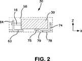
In den
Zur Bildung der Anode können im Allgemeinen herkömmliche Herstellungsverfahren verwendet werden. In einer Ausführungsform wird zuerst ein Tantal- oder Nioboxidpulver mit einer bestimmten Teilchengröße ausgewählt. Zum Beispiel können die Teilchen flockenartig, eckig, knotenförmig sowie Gemische und Variationen davon sein. Die Teilchen haben auch typischerweise eine Siebgrößenverteilung von wenigstens etwa 60 mesh, in einigen Ausführungsformen etwa 60 bis etwa 325 mesh und in einigen Ausführungsformen etwa 100 bis etwa 200 mesh. Ferner beträgt die spezifische Oberfläche etwa 0,1 bis etwa 10,0 m2/g, in einigen Ausführungsformen etwa 0,5 bis etwa 5,0 m2/g und in einigen Ausführungsformen etwa 1,0 bis etwa 2,0 m2/g. Der Ausdruck ”spezifische Oberfläche” bezieht sich auf die Oberfläche, die durch das Verfahren der physikalischen Gasadsorption (B. E. T.) von
Um den Bau der Anode zu erleichtern, können noch weitere Komponenten zu den elektrisch leitfähigen Teilchen gegeben werden. Zum Beispiel können die elektrisch leitfähigen Teilchen gegebenenfalls mit einem Bindemittel und/oder Gleitmittel gemischt werden, um zu gewährleisten, dass die Teilchen ausreichend aneinander haften, wenn sie zum Anodenkörper gepresst werden. Zu den geeigneten Bindemitteln gehören etwa Campher, Stearin- und andere Seifenfettsäuren, Carbowax (Union Carbide), Glyptal (General Electric), Polyvinylalkohole Naphthalin, Pflanzenwachs, Mikrowachse (gereinigte Paraffine). Das Bindemittel kann in einem Lösungsmittel gelöst und dispergiert werden. Beispielhafte Lösungsmittel sind Wasser, Alkohole usw. Wenn Bindemittel und/oder Gleitmittel verwendet werden, kann ihr Prozentanteil von etwa 0,1 bis etwa 8 Gew.-% der Gesamtmasse variieren. Man sollte sich jedoch darüber im Klaren sein, dass Bindemittel und Gleitmittel in der vorliegenden Erfindung nicht erforderlich sind.To facilitate the construction of the anode, other components can be added to the electrically conductive particles. For example, the electrically conductive particles may optionally be mixed with a binder and / or lubricant to ensure that the particles adhere sufficiently to each other when pressed to the anode body. Suitable binders include camphor, stearic and other soap fatty acids, Carbowax (Union Carbide), Glyptal (General Electric), polyvinyl alcohols naphthalene, vegetable wax, microwaxes (purified paraffins). The binder can be dissolved and dispersed in a solvent. Exemplary solvents are water, alcohols, etc. When binders and / or lubricants are used, their percentage may vary from about 0.1 to about 8 percent by weight of the total mass. It should be understood, however, that binders and lubricants are not required in the present invention.
Das resultierende Pulver kann kompaktiert werden, wobei man irgendeine herkömmliche Pulverpressvorrichtung verwendet. Die Pressform kann zum Beispiel eine Einplatz-Kompaktierpresse sein, bei der eine Matrize und ein oder mehrere Stempel verwendet werden. Alternativ dazu können auch Kompaktierpressformen des Ambosstyps verwendet werden, bei denen nur eine Matrize und ein einziger Unterstempel verwendet werden. Einplatz-Kompaktierpressformen sind in mehreren Grundtypen erhältlich, wie Nocken-, Kniehebel- und Exzenter-/Kurbelpressen mit unterschiedlichen Fähigkeiten, wie einfach wirkend, doppelt wirkend, Schwebemantelmatrize, bewegliche Werkzeugaufspannplatte, Gegenstempel, Schnecke, Schlag, Heißpressen, Prägen oder Kalibrieren. Das Pulver kann um einen Anodenanschluss (z. B. Tantaldraht) herum kompaktiert werden. Man sollte sich weiterhin darüber im Klaren sein, dass der Anodenanschluss nach dem Pressen und/oder Sintern des Anodenkörpers alternativ auch an dem Anodenkörper befestigt (z. B. daran geschweißt) werden kann. Gegebenenfalls vorhandenes Bindemittel/Gleitmittel kann nach dem Pressen entfernt werden, indem man den Pressling mehrere Minuten lang im Vakuum auf eine bestimmte Temperatur (z. B. etwa 150°C bis etwa 500°C) erhitzt. Alternativ dazu kann das Bindemittel/Gleitmittel auch entfernt werden, indem man den Pressling mit einer wässrigen Lösung in Kontakt bringt, wie es im
Obwohl es nicht erforderlich ist, kann die Dicke der Anode so gewählt werden, dass die elektrischen Eigenschaften des Kondensators verbessert werden. Zum Beispiel kann die Dicke der Anode etwa 4 Millimeter oder weniger betragen, in einigen Ausführungsformen etwa 0,05 bis etwa 2 Millimeter und in einigen Ausführungsformen etwa 0,1 bis etwa 1 Millimeter. Auch die Form der Anode kann so gewählt werden, dass die elektrischen Eigenschaften des resultierenden Kondensators verbessert werden. Zum Beispiel kann die Anode eine Form haben, die gekrümmt, wellenförmig, rechteckig, U-förmig, V-förmig usw. ist. Die Anode kann auch eine ”geriffelte” Form haben, indem sie eine oder mehrere Furchen, Rillen, Vertiefungen oder Einkerbungen enthält, um das Verhältnis von Oberfläche zu Volumen zu erhöhen und dadurch den ESR zu minimieren und den Frequenzgang der Kapazität auszudehnen. Solche ”geriffelten” Anoden sind zum Beispiel in den
Ein Anodenanschluss
Sobald sie konstruiert wurde, kann die Anode anodisiert werden, so dass eine dielektrische Schicht auf und/oder innerhalb der Anode entsteht. Die Anodisierung ist ein elektrochemisches Verfahren, bei dem die Anode oxidiert wird, so dass ein Material mit einer relativ hohen Dielektrizitätskonstante entsteht. Zum Beispiel kann eine Anode aus Nioboxid (NbO) zu Niobpentoxid (Nb2O5) anodisiert werden. Typischerweise wird die Anodisierung durchgeführt, indem man zunächst einen Elektrolyten auf die Anode aufträgt, etwa durch Eintauchen der Anode in den Elektrolyten. Der Elektrolyt liegt im Allgemeinen in Form einer Flüssigkeit vor, etwa als Lösung (z. B. wässrig oder nichtwässrig), Dispersion, Schmelze usw. In dem Elektrolyten wird im Allgemeinen ein Lösungsmittel eingesetzt, wie Wasser (z. B. deionisiertes Wasser), Ether (z. B. Diethylether und Tetrahydrofuran), Alkohole (z. B. Methanol, Ethanol, n-Propanol, Isopropanol und Butanol), Triglyceride, Ketone, (z. B. Aceton, Methylethylketon und Methylisobutylketon); Ester (z. B. Ethylacetat, Butylacetat, Diethylenglycoletheracetat und Methoxypropylacetat); Amide (z. B. Dimethylformamid, Dimethylacetamid, Dimethylcapryl-/caprinfettsäureamid und N-Alkylpyrrolidone), Nitrile (z. B. Acetonitril, Propionitril, Butyronitril und Benzonitril), Sulfoxide oder Sulfone (z. B. Dimethylsulfoxid (DMSO) und Sulfolan) usw. Das Lösungsmittel kann etwa 50 Gew.-% bis etwa 99,9 Gew.-%, in einigen Ausführungsformen etwa 75 Gew.-% bis etwa 99 Gew.-% und in einigen Ausführungsformen etwa 80 Gew.-% bis etwa 95 Gew.-% des Elektrolyten ausmachen. Obwohl es nicht unbedingt erforderlich ist, ist die Verwendung eines wässrigen Lösungsmittels (z. B. Wasser) häufig wünschenswert, um dabei zu helfen, das gewünschte Oxid zu erreichen. Tatsächlich kann Wasser etwa 50 Gew.-% oder mehr, in einigen Ausführungsformen etwa 70 Gew.-% oder mehr und in einigen Ausführungsformen etwa 90 Gew.-% bis 100 Gew.-% der in dem Elektrolyten verwendeten Lösungsmittel ausmachen.Once constructed, the anode can be anodized to form a dielectric layer on and / or within the anode. Anodization is an electrochemical process in which the anode is oxidized to form a material with a relatively high dielectric constant. For example, an anode of niobium oxide (NbO) can be anodized to niobium pentoxide (Nb2 O5 ). Typically, the anodization is performed by first applying an electrolyte to the anode, such as by immersing the anode in the electrolyte. The electrolyte is generally in the form of a liquid, such as a solution (eg, aqueous or nonaqueous), dispersion, melt, etc. The electrolyte generally uses a solvent, such as water (eg, deionized water), Ethers (e.g., diethyl ether and tetrahydrofuran), alcohols (e.g., methanol, ethanol, n-propanol, isopropanol, and butanol), triglycerides, ketones (e.g., acetone, methyl ethyl ketone, and methyl isobutyl ketone); Esters (e.g., ethyl acetate, butyl acetate, diethylene glycol ether acetate and methoxypropyl acetate); Amides (eg, dimethylformamide, dimethylacetamide, dimethylcaprylic / capric fatty acid amide, and N-alkylpyrrolidones), nitriles (eg, acetonitrile, propionitrile, butyronitrile, and benzonitrile), sulfoxides or sulfones (eg, dimethylsulfoxide (DMSO) and sulfolane) etc. The solvent may be about 50% to about 99.9% by weight, in some embodiments about 75% to about 99%, and in some embodiments about 80% to about 95% Make up wt% of the electrolyte. Although not strictly required, the use of an aqueous solvent (eg, water) is often desirable to help achieve the desired oxide. In fact, water may constitute about 50% by weight or more, in some embodiments about 70% or more, and in some embodiments about 90% to 100%, by weight of the solvent used in the electrolyte.
Der Elektrolyt ist ionenleitend und kann eine Ionenleitfähigkeit von etwa 1 Millisiemens pro Zentimeter (”mS/cm”) oder mehr aufweisen, in einigen Ausführungsformen etwa 30 mS/cm oder mehr und in einigen Ausführungsformen etwa 40 mS/cm bis etwa 100 mS/cm, bestimmt bei einer Temperatur von 25°C. Um die Ionenleitfähigkeit des Elektrolyten zu verstärken, kann eine Verbindung eingesetzt werden, die in dem Lösungsmittel unter Bildung von Ionen dissoziieren kann. Geeignete ionische Verbindungen für diesen Zweck sind zum Beispiel Säuren, wie Chlorwasserstoffsäure, Salpetersäure, Schwefelsäure, Phosphorsäure, Polyphosphorsäure, Borsäure, Boronsäure usw., organische Säuren einschließlich Carbonsäuren, wie Acrylsäure, Methacrylsäure, Malonsäure, Bernsteinsäure, Salicylsäure, Sulfosalicylsäure, Adipinsäure, Maleinsäure, Äpfelsäure, Ölsäure, Gallsäure, Weinsäure, Zitronensäure, Ameisensäure, Essigsäure, Glycolsäure, Oxalsäure, Propionsäure, Phthalsäure, Isophthalsäure, Glutarsäure, Gluconsäure, Milchsäure, Asparaginsäure, Glutaminsäure, Itaconsäure, Trifluoressigsäure, Barbitursäure, Zimtsäure, Benzoesäure, 4-Hydroxybenzoesäure, Aminobenzoesäure usw., Sulfonsäuren, wie Methansulfonsäure, Benzolsulfonsäure, Toluolsulfonsäure, Trifluormethansulfonsäure, Styrolsulfonsäure, Naphthalindisulfonsäure, Hydroxybenzolsulfonsäure, Dodecylsulfonsäure, Dodecylbenzolsulfonsäure usw., polymere Säuren, wie Polyacryl- oder Polymethacrylsäure und Copolymere davon (z. B. Maleinsäure-Acrylsäure-, Sulfonsäure-Acrylsäure- und Styrol-Acrylsäure-Copolymere), Carrageensäure, Carboxymethylcellulose, Alginsäure usw., usw. Die Konzentration der ionischen Verbindungen wird so gewählt, dass die gewünschte Ionenleitfähigkeit erreicht wird. Zum Beispiel kann eine Säure (z. B. Phosphorsäure) etwa 0,01 Gew.-% bis etwa 5 Gew.-%, in einigen Ausführungsformen etwa 0,05 Gew.-% bis etwa 0,8 Gew.-% und in einigen Ausführungsformen etwa 0,1 Gew.-% bis etwa 0,5 Gew.-% des Elektrolyten ausmachen. Falls gewünscht, können in dem Elektrolyten auch Gemische von ionischen Verbindungen eingesetzt werden.The electrolyte is ion conducting and may have an ionic conductivity of about 1 milliSiemens per centimeter ("mS / cm") or more, in some embodiments about 30 mS / cm or more, and in some embodiments about 40 mS / cm to about 100 mS / cm , determined at a temperature of 25 ° C. In order to enhance the ionic conductivity of the electrolyte, a compound may be used which can dissociate in the solvent to form ions. Suitable ionic compounds for this purpose are, for example, acids such as hydrochloric acid, nitric acid, sulfuric acid, phosphoric acid, polyphosphoric acid, boric acid, boronic acid, etc., organic acids including carboxylic acids such as acrylic acid, methacrylic acid, malonic acid, succinic acid, salicylic acid, sulfosalicylic acid, adipic acid, maleic acid, Malic, oleic, gallic, tartaric, citric, formic, acetic, glycolic, oxalic, propionic, phthalic, isophthalic, glutaric, gluconic, lactic, aspartic, glutamic, itaconic, trifluoroacetic, barbituric, cinnamic, benzoic, 4-hydroxybenzoic, aminobenzoic, etc , Sulfonic acids such as methanesulfonic acid, benzenesulfonic acid, toluenesulfonic acid, trifluoromethanesulfonic acid, styrenesulfonic acid, naphthalenedisulfonic acid, hydroxybenzenesulfonic acid, dodecylsulfonic acid, dodecylbenzenesulfonic acid, etc., polymeric acids such as Pol yacrylic or polymethacrylic acid and copolymers thereof (for example, maleic acid-acrylic acid, sulfonic acid-acrylic acid and styrene-acrylic acid copolymers), carrageenic acid, carboxymethyl cellulose, alginic acid, etc., etc. The concentration of the ionic compounds is selected so that the desired ionic conductivity is achieved. For example, an acid (eg, phosphoric acid) may be from about 0.01% to about 5% by weight, in some embodiments from about 0.05% to about 0.8% by weight, and in In some embodiments, from about 0.1% to about 0.5% by weight of the electrolyte. If desired, mixtures of ionic compounds may also be employed in the electrolyte.
Ein Strom wird durch den Elektrolyten geleitet, um die dielektrische Schicht zu bilden. Der Wert der Spannung entspricht der Dicke der dielektrischen Schicht. Zum Beispiel kann die Stromquelle zunächst im galvanostatischen Modus betrieben werden, bis die erforderliche Spannung erreicht ist. Danach kann die Stromquelle auf einen potentiostatischen Modus umgeschaltet werden, um zu gewährleisten, dass die gewünschte Dicke des Dielektrikums über der Oberfläche der Anode gebildet wird. Selbstverständlich können auch andere bekannte Verfahren eingesetzt werden, wie potentiostatische Impuls- oder Schrittverfahren. Die Spannung liegt typischerweise im Bereich von etwa 4 bis etwa 200 V und in einigen Ausführungsformen etwa 9 bis etwa 100 V. Während der anodischen Oxidation kann der Elektrolyt auf einer erhöhten Temperatur gehalten werden, wie etwa 30°C oder mehr, in einigen Ausführungsformen etwa 40°C bis etwa 200°C und in einigen Ausführungsformen etwa 50°C bis etwa 100°C. Die anodische Oxidation kann auch bei Umgebungstemperatur oder darunter durchgeführt werden. Die resultierende dielektrische Schicht kann auf einer Oberfläche der Anode oder innerhalb ihrer Poren gebildet werden.A current is passed through the electrolyte to form the dielectric layer. The value of the voltage corresponds to the thickness of the dielectric layer. For example, the power source may first be operated in the galvanostatic mode until the required voltage is reached. Thereafter, the power source may be switched to a potentiostatic mode to ensure that the desired thickness of the dielectric is formed over the surface of the anode. Of course, other known methods can be used, such as potentiostatic pulse or step method. The voltage is typically in the range of about 4 to about 200 V, and in some embodiments about 9 to about 100 V. During anodic oxidation, the electrolyte may be maintained at an elevated temperature, such as 30 ° C or more, in some embodiments, for example 40 ° C to about 200 ° C and in some embodiments about 50 ° C to about 100 ° C. The anodic oxidation may also be carried out at ambient temperature or below. The resulting dielectric layer may be formed on a surface of the anode or within its pores.
Sobald die dielektrische Schicht gebildet ist, kann gegebenenfalls eine Schutzbeschichtung aufgetragen werden, zum Beispiel eine, die aus einem relativ isolierenden harzartigen Material (natürlich oder synthetisch) besteht. Solche Materialien können einen spezifischen Widerstand von mehr als etwa 10 Ohm·cm haben, in einigen Ausführungsformen mehr als etwa 100, in einigen Ausführungsformen mehr als etwa 1000 Ohm·cm, in einigen Ausführungsformen mehr als etwa 1 × 10⁵ Ohm·cm und in einigen Ausführungsformen mehr als etwa 1 × 10¹⁰ Ohm·cm. Einige harzartige Materialien, die in der vorliegenden Erfindung verwendet werden können, sind unter anderem Polyurethan, Polystyrol, Ester von ungesättigten oder gesättigten Fettsäuren (z. B. Glyceride) usw. Zu den geeigneten Estern von Fettsäuren gehören zum Beispiel unter anderem Ester von Laurinsäure, Myristinsäure, Palmitinsäure, Stearinsäure, Eleostearinsäure, Ölsäure, Linolsäure, Linolensäure, Aleuritinsäure, Schellolsäure usw. Diese Ester von Fettsäuren haben sich als besonders nützlich erwiesen, wenn sie in relativ komplexen Kombinationen unter Bildung eines ”trocknenden Öls” verwendet werden, das es dem resultierenden Film ermöglicht, schnell zu einer stabilen Schicht zu polymerisieren. Zu diesen trocknenden Ölen gehören etwa Mono-, Di- und/oder Triglyceride, die ein Glyceringerüst mit einem, zwei bzw. drei Fettacylresten, die verestert sind, aufweisen. Einige geeignete trocknende Öle, die verwendet werden können, sind zum Beispiel unter anderem Olivenöl, Leinöl, Ricinusöl, Tungöl, Sojaöl und Schellack. Diese und andere Schutzbeschichtungsmaterialien sind ausführlicher im
Danach wird das anodisierte Teil einem Schritt zur Bildung einer Kathode, die einen festen Elektrolyten, wie Mangandioxid, ein leitfähiges Polymer usw. enthält, unterzogen. Ein fester Elektrolyt in Form von Mangandioxid kann zum Beispiel durch pyrolytische Zersetzung von Mangannitrat (Mn(NO3)2)) gebildet werden. Solche Techniken sind zum Beispiel im
Es kann auch eine leitfähige Polymerbeschichtung eingesetzt werden, die einen oder mehrere Polyheterocyclen (z. B. Polypyrrole, Polythiophene, Poly(3,4-ethylendioxythiophen) (PEDT), Polyaniline), Polyacetylene, Poly-p-phenylene, Polyphenolate und Derivate davon enthält. Die leitfähige Polymerbeschichtung kann auch aus mehreren leitfähigen Polymerschichten gebildet werden. Zum Beispiel kann die Kathode aus dem leitfähigen Polymer in einer Ausführungsform eine aus PEDT gebildete Schicht und eine andere, aus einem Polypyrrol gebildete Schicht enthalten. Verschiedene Verfahren können verwendet werden, um die leitfähige Polymerbeschichtung auf den Anodenteil aufzutragen. Zum Beispiel können herkömmliche Techniken, wie Elektropolymerisation, Siebdruck, Tauchbeschichtung, elektrophoretische Beschichtung und Sprühbeschichtung, verwendet werden, um eine leitfähige Polymerbeschichtung zu bilden.It is also possible to use a conductive polymer coating comprising one or more polyheterocycles (for example polypyrroles, polythiophenes, poly (3,4-ethylenedioxythiophene) (PEDT), polyanilines), polyacetylenes, poly-p-phenylenes, polyphenolates and derivatives thereof contains. The conductive polymer coating may also be formed from multiple conductive polymer layers. For example, in one embodiment, the conductive polymer cathode may include a layer formed of PEDT and another layer formed of a polypyrrole. Various methods can be used to apply the conductive polymer coating to the anode part. For example, conventional techniques such as electropolymerization, screen printing, dip coating, electrophoretic coating and spray coating can be used to form a conductive polymer coating.
In einer besonderen Ausführungsform enthält die leitfähige Beschichtung ein substituiertes Polythiophen, das π-konjugiert ist und eine intrinsische elektrische Leitfähigkeit aufweist (z. B. eine elektrische Leitfähigkeit von wenigstens etwa 1 μS·cm–1). Das substituierte Polythiophen kann Repetiereinheiten der allgemeinen Formel (I), Formel (II) oder von beiden aufweisen:
A ein gegebenenfalls substituierter C1- bis C5-Alkylenrest (z. B. Methylen, Ethylen, n-Propylen, n-Butylen, n-Pentylen usw.) ist;
R ein linearer oder verzweigter, gegebenenfalls substituierter C1- bis C18-Alkylrest (z. B. Methyl, Ethyl, n- oder iso-Propyl, n-, iso-, sek- oder tert-Butyl, n-Pentyl, 1-Methylbutyl, 2-Methylbutyl, 3-Methylbutyl, 1-Ethylpropyl, 1,1-Dimethylpropyl, 1,2-Dimethylpropyl, 2,2-Dimethylpropyl, n-Hexyl, n-Heptyl, n-Octyl, 2-Ethylhexyl, n-Nonyl, n-Decyl, n-Undecyl, n-Dodecyl, n-Tridecyl, n-Tetradecyl, n-Hexadecyl, n-Octadecyl usw.); gegebenenfalls substituierter C5- bis C12-Cycloalkylrest (z. B. Cyclopentyl, Cyclohexyl, Cycloheptyl, Cyclooctyl, Cyclononyl, Cyclodecyl usw.); gegebenenfalls substituierter C6- bis C14-Arylrest (z. B. Phenyl, Naphthyl usw.); gegebenenfalls substituierter C7- bis C18-Aralkylrest (z. B. Benzyl, o-, m-, p-Tolyl, 2,3-, 2,4-, 2,5-, 2,6-, 3,4-, 3,5-Xylyl, Mesityl usw.); gegebenenfalls substituierter C1- bis C4-Hydroxyalkylrest oder Hydroxyrest ist; und
x eine ganze Zahl von 0 bis 8, in einigen Ausführungsformen von 0 bis 2, ist und x in einigen Ausführungsformen = 0 ist. Beispiele für Substituenten für die Reste ”A” oder ”R” sind zum Beispiel Alkyl, Cycloalkyl, Aryl, Aralkyl, Alkoxy, Halogen, Ether, Thioether, Disulfid, Sulfoxid, Sulfon, Sulfonat, Amino, Aldehyd, Keto, Carbonsäureester, Carbonsäure, Carbonat, Carboxylat, Cyano, Alkylsilan- und Alkoxysilangruppen, Carboxylamidgruppen usw.In a particular embodiment, the conductive coating contains a substituted polythiophene which is π-conjugated and has intrinsic electrical conductivity (eg, an electrical conductivity of at least about 1 μS · cm-1 ). The substituted polythiophene may have repeating units of the general formula (I), formula (II) or both:
A is an optionally substituted C1 to C5 alkylene radical (eg, methylene, ethylene, n-propylene, n-butylene, n-pentylene, etc.);
R is a linear or branched, optionally substituted C1 - to C18 -alkyl radical (eg., Methyl, ethyl, n- or iso-propyl, n-, iso-, sec- or tert-butyl, n-pentyl, 1 Methylbutyl, 2-methylbutyl, 3-methylbutyl, 1-ethylpropyl, 1,1-dimethylpropyl, 1,2-dimethylpropyl, 2,2-dimethylpropyl, n -hexyl, n-heptyl, n-octyl, 2-ethylhexyl, n Nonyl, n-decyl, n-undecyl, n-dodecyl, n-tridecyl, n-tetradecyl, n-hexadecyl, n-octadecyl, etc.); optionally substituted C5 to C12 cycloalkyl (eg, cyclopentyl, cyclohexyl, cycloheptyl, cyclooctyl, cyclononyl, cyclodecyl, etc.); optionally substituted C6 to C14 aryl radical (eg, phenyl, naphthyl, etc.); optionally substituted C7 - to C18 -aralkyl radical (eg benzyl, o-, m-, p-tolyl, 2,3-, 2,4-, 2,5-, 2,6-, 3,4 -, 3,5-xylyl, mesityl, etc.); optionally substituted C1 to C4 hydroxyalkyl or hydroxy; and
x is an integer from 0 to 8, in some embodiments from 0 to 2, and x is = 0 in some embodiments. Examples of substituents for the radicals "A" or "R" are, for example, alkyl, cycloalkyl, aryl, aralkyl, alkoxy, halogen, ether, thioether, disulfide, sulfoxide, sulfone, sulfonate, amino, aldehyde, keto, carboxylic acid ester, carboxylic acid, Carbonate, carboxylate, cyano, alkylsilane and alkoxysilane groups, carboxylamide groups, etc.
Die Gesamtzahl der Repetiereinheiten der allgemeinen Formel (I) oder Formel (II) oder der allgemeinen Formeln (I) und (II) beträgt typischerweise 2 bis 2000 und in einigen Ausführungsformen 2 bis 100.The total number of recurring units of general formula (I) or formula (II) or general formulas (I) and (II) is typically 2 to 2000 and in some embodiments 2 to 100.
Besonders gut geeignete substituierte Polythiophene sind solche, bei denen ”A” ein gegebenenfalls substituierter C2- bis C3-Alkylenrest ist und x = 0 oder 1 ist. In einer besonderen Ausführungsform handelt es sich bei dem substituierten Polythiophen um Poly(3,4-ethylendioxythiophen) (”PEDT”), das Repetiereinheiten der Formel (II) aufweist, wobei ”A” = CH2-CH2 ist und ”x” = 0 ist. Die zur Bildung solcher Polymere verwendeten Monomere können nach Wunsch variieren. Besonders gut geeignete Monomere sind zum Beispiel substituierte 3,4-Alkylendioxythiophene mit der allgemeinen Formel (III), (IV) oder beiden:
Beispiele für solche Monomere sind zum Beispiel gegebenenfalls substituierte 3,4-Ethylendioxythiophene. Ein kommerziell geeignetes Beispiel für 3,4-Ethylendioxythiophen ist von der H. C. Starck GmbH unter der Bezeichnung CleviosTMM erhältlich. Es können auch Derivate dieser Monomere eingesetzt werden, die zum Beispiel Dimere oder Trimere der obigen Monomere sind. Höhermolekulare Derivate, d. h. Tetramere, Pentamere usw., der Monomere sind zur Verwendung in der vorliegenden Erfindung geeignet. Die Derivate können aus gleichen oder verschiedenen Monomereinheiten bestehen und können in reiner Form oder in einem Gemisch miteinander und/oder mit den Monomeren verwendet werden. Oxidierte oder reduzierte Formen dieser Vorläufer können ebenfalls eingesetzt werden.Examples of such monomers are, for example, optionally substituted 3,4-ethylenedioxythiophenes. A commercially suitable example of 3,4-ethylenedioxythiophene is available from HC Starck GmbH under the name Clevios™ M. It is also possible to use derivatives of these monomers which are, for example, dimers or trimers of the above monomers. Higher molecular weight derivatives, ie, tetramers, pentamers, etc., of the monomers are suitable for use in the present invention. The derivatives may consist of the same or different monomer units and may be used in pure form or in admixture with each other and / or with the monomers. Oxidized or reduced forms of these precursors can also be used.
Die Thiophenmonomere, wie sie oben beschrieben sind, können in Gegenwart eines oxidativen Katalysators chemisch polymerisiert werden. Der oxidative Katalysator umfasst typischerweise ein Übergangsmetallkation, wie Eisen(III)-, Kupfer(II)-, Chrom(VI)-, Cer(IV)-, Mangan(IV)-, Mangan(VII)-, Ruthenium(III)-Kationen usw. Ein Dotierungsmittel kann auch eingesetzt werden, um dem leitfähigen Polymer überschüssige Ladung zu verleihen und die Leitfähigkeit des Polymers zu stabilisieren. Das Dotierungsmittel umfasst typischerweise ein anorganisches oder organisches Anion, wie ein Ion einer Sulfonsäure. In bestimmten Ausführungsformen weist der in der Vorläuferlösung eingesetzte oxidative Katalysator sowohl eine katalytische als auch eine dotierende Funktionalität auf, indem er ein Kation (z. B. Übergangsmetall) und ein Anion (z. B. Sulfonsäure) umfasst. Zum Beispiel kann der oxidative Katalysator ein Übergangsmetallsalz sein, das Eisen(III)-Kationen, wie Eisen(III)halogenide (z. B. FeCl3) oder Eisen(III)-Salze anderer anorganischer Säuren, wie Fe(ClO4)3 oder Fe2(SO4)3, und die Eisen(III)-Salze von organischen Säuren und anorganischen Säuren, die organische Reste umfassen, umfasst. Beispiele für Eisen(III)-Salze von anorganischen Säuren mit organischen Resten sind zum Beispiel Eisen(III)-Salze von Schwefelsäuremonoestern von C1- bis C20-Alkanolen (z. B. das Eisen(III)-Salz von Laurylsulfat). Ebenso sind Beispiele für Eisen(III)-Salze von organischen Säuren zum Beispiel Eisen(III)-Salze von C1- bis C20-Alkansulfonsäuren (z. B. Methan-, Ethan-, Propan-, Butan- oder Dodecansulfonsäure); Eisen(III)-Salze von aliphatischen Perfluorsulfonsäuren (z. B. Trifluormethansulfonsäure, Perfluorbutansulfonsäure oder Perfluoroctansulfonsäure); Eisen(III)-Salze von aliphatischen C1- bis C20-Carbonsäuren (z. B. 2-Ethylhexylcarbonsäure); Eisen(III)-Salze von aliphatischen Perfluorcarbonsäuren (z. B. Trifluoressigsäure oder Perfluoroctansäure); Eisen(III)-Salze von aromatischen Sulfonsäuren, die gegebenenfalls mit C1- bis C20-Alkylgruppen substituiert sind (z. B. Benzolsulfonsäure, o-Toluolsulfonsäure, p-Toluolsulfonsäure oder Dodecylbenzolsulfonsäure); Eisen(III)-Salze von Cycloalkansulfonsäuren (z. B. Camphersulfonsäure); usw. Gemische dieser oben genannten Eisen(III)-Salze können ebenfalls verwendet werden. Eisen(III)-p-toluolsulfonat, Eisen(III)-o-toluolsulfonat und Gemische davon sind zur Verwendung in der vorliegenden Erfindung besonders gut geeignet. Ein kommerziell geeignetes Beispiel für Eisen(III)-p-toluolsulfonat ist von der H. C. Starck GmbH unter der Bezeichnung CleviosTMC erhältlich.The thiophene monomers as described above can be chemically polymerized in the presence of an oxidative catalyst. The oxidative catalyst typically comprises a transition metal cation such as iron (III), copper (II), chromium (VI), cerium (IV), manganese (IV), manganese (VII), ruthenium (III) Cations, etc. A dopant may also be employed to impart excess charge to the conductive polymer and to stabilize the conductivity of the polymer. The dopant typically comprises an inorganic or organic anion, such as an ion of a sulfonic acid. In certain embodiments, the oxidative catalyst employed in the precursor solution has both catalytic and doping functionality by containing a cation (eg, transition metal) and an anion (eg, sulfonic acid). includes. For example, the oxidative catalyst may be a transition metal salt containing ferric cations such as ferric halides (eg FeCl3 ) or ferric salts of other inorganic acids such as Fe (ClO4 )3 or Fe2 (SO4 )3 , and the ferric salts of organic acids and inorganic acids comprising organic radicals. Examples of iron (III) salts of inorganic acids with organic radicals are, for example, iron (III) salts of sulfuric acid monoesters of C1 to C20 alkanols (for example the iron (III) salt of lauryl sulfate). Likewise, examples of iron (III) salts of organic acids are, for example, iron (III) salts of C1 to C20 alkanesulfonic acids (eg methane, ethane, propane, butane or dodecane sulfonic acid); Iron (III) salts of aliphatic perfluorosulfonic acids (eg trifluoromethanesulfonic acid, perfluorobutanesulfonic acid or perfluorooctanesulfonic acid); Iron (III) salts of aliphatic C1 to C20 carboxylic acids (eg 2-ethylhexylcarboxylic acid); Ferric salts of aliphatic perfluorocarboxylic acids (eg, trifluoroacetic acid or perfluorooctanoic acid); Ferric salts of aromatic sulfonic acids optionally substituted with C1 to C20 alkyl groups (for example, benzenesulfonic acid, o-toluenesulfonic acid, p-toluenesulfonic acid or dodecylbenzenesulfonic acid); Ferric salts of cycloalkanesulfonic acids (eg, camphorsulfonic acid); etc. Mixtures of these above-mentioned ferric salts may also be used. Iron (III) p-toluenesulfonate, ferric o-toluenesulfonate and mixtures thereof are particularly well suited for use in the present invention. A commercially suitable example of iron (III) p-toluenesulfonate is available from HC Starck GmbH under the name Clevios™ C.
Verschiedene Verfahren können verwendet werden, um die leitfähige Beschichtung zu bilden. In einer Ausführungsform werden der oxidative Katalysator und das Monomer entweder nacheinander oder zusammen aufgetragen, so dass die Polymerisationsreaktion in situ auf dem Teil stattfindet. Geeignete Auftragstechniken, wie Siebdruck, Tauchbeschichtung, elektrophoretische Beschichtung und Sprühbeschichtung, können verwendet werden, um eine leitfähige Polymerbeschichtung zu bilden. Als Beispiel kann das Monomer zunächst unter Bildung einer Vorläuferlösung mit dem oxidativen Katalysator gemischt werden. Sobald das Gemisch gebildet ist, kann es aufgetragen und polymerisieren gelassen werden, so dass die leitfähige Beschichtung auf der Oberfläche entsteht. Alternativ dazu können der oxidative Katalysator und das Monomer auch nacheinander aufgetragen werden. In einer Ausführungsform wird der oxidative Katalysator zum Beispiel in einem organischen Lösungsmittel (z. B. Butanol) gelöst und dann als Tauchlösung aufgetragen. Der Teil kann dann getrocknet werden, um das Lösungsmittel davon zu entfernen. Danach kann der Teil in eine Lösung, die das Monomer enthält, eingetaucht werden.Various methods can be used to form the conductive coating. In one embodiment, the oxidative catalyst and the monomer are applied either sequentially or together so that the polymerization reaction takes place in situ on the part. Suitable application techniques such as screen printing, dip coating, electrophoretic coating and spray coating can be used to form a conductive polymer coating. As an example, the monomer may be first mixed with the oxidative catalyst to form a precursor solution. Once the mixture is formed, it can be applied and polymerized to form the conductive coating on the surface. Alternatively, the oxidative catalyst and the monomer may also be applied sequentially. For example, in one embodiment, the oxidative catalyst is dissolved in an organic solvent (eg, butanol) and then applied as a dipping solution. The part may then be dried to remove the solvent therefrom. Thereafter, the part may be immersed in a solution containing the monomer.
Die Polymerisation wird typischerweise je nach dem verwendeten Oxidationsmittel und der gewünschten Reaktionszeit bei Temperaturen von etwa –10°C bis etwa 250°C und in einigen Ausführungsformen etwa 0°C bis etwa 200°C durchgeführt. Geeignete Polymerisationstechniken, wie sie oben beschrieben sind, sind ausführlicher in der US-Veröffentlichungs-Nr. 7,515,396 (Biler) beschrieben. Noch andere Verfahren zum Auftragen einer oder mehrerer solcher leitfähigen Polymerbeschichtungen sind in den
Neben der oder in Verbindung mit der Beschichtung, die durch in-situ-Auftragung gebildet wird, kann auch eine leitfähige Beschichtung, die in Form einer Dispersion von leitfähigen Polymerteilchen vorliegt, eingesetzt werden. Obwohl ihre Größe variieren kann, ist es typischerweise wünschenswert, dass die Teilchen einen kleinen Durchmesser besitzen, um die zum Befestigen des Anodenteils verfügbare Oberfläche zu vergrößern. Zum Beispiel können die Teilchen einen mittleren Durchmesser von etwa 1 bis etwa 500 Nanometer, in einigen Ausführungsformen etwa 5 bis etwa 400 Nanometer und in einigen Ausführungsformen etwa 10 bis etwa 300 Nanometer haben. Der D90-Wert der Teilchen (Teilchen mit einem Durchmesser kleiner oder gleich dem D90-Wert bilden 90% des Gesamtvolumens aller festen Teilchen) kann etwa 15 Mikrometer oder weniger, in einigen Ausführungsformen etwa 10 Mikrometer oder weniger und in einigen Ausführungsformen etwa 1 Nanometer bis etwa 8 Mikrometer betragen. Der Durchmesser der Teilchen kann mit Hilfe bekannter Techniken, wie mittels Ultrazentrifuge, Laserbeugung usw., bestimmt werden.In addition to or in conjunction with the coating formed by in situ deposition, a conductive coating that is in the form of a dispersion of conductive polymer particles may also be employed. Although their size may vary, it is typically desirable for the particles to have a small diameter in order to increase the surface area available for attaching the anode part. For example, the particles may have a mean diameter of about 1 to about 500 nanometers, in some embodiments about 5 to about 400 nanometers, and in some embodiments, about 10 to about 300 nanometers. The D90 value of the particles (particles having a diameter less than or equal to D90 value constitute 90% of the total volume of all solid particles) may be about 15 micrometers or less, in some embodiments, about 10 microns or less, and in some embodiments from about 1 Nanometers to about 8 microns. The diameter of the particles can be determined by known techniques such as ultracentrifuge, laser diffraction, etc.
Die Verarbeitung der leitfähigen Polymere in eine Teilchenform kann verstärkt werden, indem man ein getrenntes Gegenion verwendet, das der positiven Ladung des substituierten Polythiophens entgegenwirken soll. In einigen Fällen kann das Polymer positive und negative Ladungen in der Struktureinheit besitzen, wobei sich die positive Ladung auf der Hauptkette und die negative Ladung gegebenenfalls auf den Substituenten des Restes ”R”, wie Sulfonat- oder Carboxylatgruppen, befindet. Die positiven Ladungen der Hauptkette können teilweise oder zur Gänze mit den gegebenenfalls vorhandenen anionischen Gruppen an den Resten ”R” gesättigt sein. Insgesamt gesehen können die Polythiophene in diesen Fällen kationisch, neutral oder sogar anionisch sein. Dennoch werden sie alle als kationische Polythiophene angesehen, da die Polythiophen-Hauptkette eine positive Ladung trägt.The processing of the conductive polymers into a particulate form can be enhanced by using a separate counterion to counteract the positive charge of the substituted polythiophene. In some cases, the polymer may have positive and negative charges in the structural unit, with the positive charge on the main chain and the negative charge optionally on the substituents of the radical "R", such as sulfonate or carboxylate groups. The positive charges of the main chain can be partially or completely saturated with the optionally present anionic groups on the radicals "R". Overall, the polythiophenes in these cases can be cationic, neutral or even anionic. Nevertheless, they are all considered cationic polythiophenes because the polythiophene backbone carries a positive charge.
Das Gegenion kann ein monomeres oder polymeres Anion sein. Polymere Anionen können zum Beispiel Anionen von polymeren Carbonsäuren (z. B. Polyacrylsäuren, Polymethacrylsäure, Polymaleinsäuren usw.), polymeren Sulfonsäuren (z. B. Polystyrolsulfonsäuren (”PSS”), Polyvinylsulfonsäuren usw.) usw. sein. Die Säuren können auch Copolymere, wie Copolymere von Vinylcarbon- und Vinylsulfonsäure mit anderen polymerisierbaren Monomeren, wie Acrylsäureestern und Styrol, sein. Ebenso sind geeignete monomere Anionen zum Beispiel Anionen von C1- bis C20-Alkansulfonsäuren (z. B. Dodecansulfonsäure); aliphatischen Perfluorsulfonsäuren (z. B. Trifluormethansulfonsäure, Perfluorbutansulfonsäure oder Perfluoroctansulfonsäure); aliphatischen C1- bis C20-Carbonsäuren (z. B. 2-Ethylhexylcarbonsäure); aliphatischen Perfluorcarbonsäuren (z. B. Trifluoressigsäure oder Perfluoroctansäure); aromatischen Sulfonsäuren, die gegebenenfalls mit C1- bis C20-Alkylgruppen substituiert sind (z. B. Benzolsulfonsäure, o-Toluolsulfonsäure, p-Toluolsulfonsäure oder Dodecylbenzolsulfonsäure); Cycloalkansulfonsäuren (z. B. Kamphersulfonsäure oder Tetrafluoroborate, Hexafluorophosphate, Perchlorate, Hexafluoroantimonate, Hexafluoroarsenate oder Hexachloroantimonate); usw. Besonders gut geeignete Gegenionen sind polymere Anionen, wie eine polymere Carbon- oder Sulfonsäure (z. B. Polystyrolsulfonsäure (”PSS”)). Das Molekulargewicht solcher polymeren Anionen liegt typischerweise im Bereich von etwa 1000 bis etwa 2000000 und in einigen Ausführungsformen etwa 2000 bis etwa 500000. The counterion may be a monomeric or polymeric anion. Polymeric anions may be, for example, anions of polymeric carboxylic acids (eg, polyacrylic acids, polymethacrylic acid, polymaleic acids, etc.), polymeric sulfonic acids (eg, polystyrenesulfonic acids ("PSS"), polyvinylsulfonic acids, etc.), etc. The acids may also be copolymers such as copolymers of vinylcarboxylic and vinylsulfonic acid with other polymerizable monomers such as acrylic esters and styrene. Likewise, suitable monomeric anions are, for example, anions of C1 to C20 alkanesulfonic acids (eg dodecanesulfonic acid); aliphatic perfluorosulfonic acids (eg trifluoromethanesulfonic acid, perfluorobutanesulfonic acid or perfluorooctanesulfonic acid); aliphatic C1 to C20 carboxylic acids (eg, 2-ethylhexylcarboxylic acid); aliphatic perfluorocarboxylic acids (eg, trifluoroacetic acid or perfluorooctanoic acid); aromatic sulfonic acids optionally substituted with C1 to C20 alkyl groups (for example, benzenesulfonic acid, o-toluenesulfonic acid, p-toluenesulfonic acid or dodecylbenzenesulfonic acid); Cycloalkanesulfonic acids (eg, camphorsulfonic acid or tetrafluoroborates, hexafluorophosphates, perchlorates, hexafluoroantimonates, hexafluoroarsenates or hexachloroantimonates); etc. Particularly suitable counterions are polymeric anions, such as a polymeric carboxylic or sulfonic acid (eg, polystyrene sulfonic acid ("PSS")). The molecular weight of such polymeric anions is typically in the range of about 1,000 to about 2,000,000, and in some embodiments about 2,000 to about 500,000.
Wenn sie eingesetzt werden, beträgt das Gewichtsverhältnis solcher Gegenionen zu substituierten Polythiophenen in einer gegebenen Schicht typischerweise etwa 0,5:1 bis etwa 50:1, in einigen Ausführungsformen etwa 1:1 bis etwa 30:1 und in einigen Ausführungsformen etwa 2:1 bis etwa 20:1. Das Gewicht des substituierten Polythiophens, von dem bei den oben genannten Gewichtsverhältnissen die Rede ist, bezieht sich auf den eingewogenen Anteil der verwendeten Monomere, wenn man annimmt, dass während der Polymerisation eine vollständige Umsetzung stattfindet.When employed, the weight ratio of such counterions to substituted polythiophenes in a given layer is typically from about 0.5: 1 to about 50: 1, in some embodiments from about 1: 1 to about 30: 1, and in some embodiments about 2: 1 until about 20: 1. The weight of the substituted polythiophene referred to in the above weight ratios refers to the weighed portion of the monomers used, assuming complete reaction takes place during the polymerization.
Die Dispersion kann auch ein oder mehrere Bindemittel enthalten, um die adhäsive Natur der polymeren Schicht weiter zu verstärken und auch die Stabilität der Teilchen innerhalb der Dispersion zu erhöhen. Die Bindemittel können organischer Natur sein, wie Polyvinylalkohole, Polyvinylpyrrolidone, Polyvinylchloride, Polyvinylacetate, Polyvinylbutyrate, Polyacrylsäureester, Polyacrylsäureamide, Polymethacrylsäureester, Polymethacrylsäureamide, Polyacrylnitrile, Styrol/Acrylsäureester, Vinylacetat/Acrylsäureester und Ethylen/Vinylacetat-Copolymere, Polybutadiene, Polyisoprene, Polystyrole, Polyether, Polyester, Polycarbonate, Polyurethane, Polyamide, Polyimide, Polysulfone, Melamin-Formaldehyd-Harze, Epoxyharze, Silikonharze oder Cellulosen. Es können auch Vernetzungsmittel eingesetzt werden, um die Adhäsionsfähigkeit der Bindemittel zu erhöhen. Solche Vernetzungsmittel sind zum Beispiel Melaminverbindungen, maskierte Isocyanate oder funktionelle Silane, wie 3-Glycidoxypropyltrialkoxysilan, Tetraethoxysilan und Tetraethoxysilan-Hydrolysat oder vernetzbare Polymere, wie Polyurethane, Polyacrylate oder Polyolefine, und anschließende Vernetzung. Wie in der Technik bekannt ist, können auch andere Komponenten in die Dispersion mit aufgenommen werden, wie Dispersionsmittel (z. B. Wasser), grenzflächenaktive Substanzen usw.The dispersion may also contain one or more binders to further enhance the adhesive nature of the polymeric layer and also increase the stability of the particles within the dispersion. The binders may be of organic nature, such as polyvinyl alcohols, polyvinylpyrrolidones, polyvinyl chlorides, polyvinyl acetates, polyvinyl butyrates, polyacrylic acid esters, polyacrylic acid amides, polymethacrylic acid esters, polymethacrylic acid amides, polyacrylonitriles, styrene / acrylic acid esters, vinyl acetate / acrylic esters and ethylene / vinyl acetate copolymers, polybutadienes, polyisoprenes, polystyrenes, polyethers, Polyesters, polycarbonates, polyurethanes, polyamides, polyimides, polysulfones, melamine-formaldehyde resins, epoxy resins, silicone resins or celluloses. Crosslinking agents can also be used to increase the adhesiveness of the binders. Such crosslinking agents are, for example, melamine compounds, masked isocyanates or functional silanes, such as 3-glycidoxypropyltrialkoxysilane, tetraethoxysilane and tetraethoxysilane hydrolyzate or crosslinkable polymers, such as polyurethanes, polyacrylates or polyolefins, and subsequent crosslinking. As known in the art, other components may also be included in the dispersion, such as dispersants (e.g., water), surfactants, etc.
Falls gewünscht, können einer oder mehrere der oben beschriebenen Auftragungsschritte wiederholt werden, bis die gewünschte Dicke der Beschichtung erreicht ist. In einigen Ausführungsformen wird nur eine relativ dünne Schicht der Beschichtung auf einmal gebildet. Die gewünschte Gesamtdicke der Beschichtung kann im Allgemeinen je nach den gewünschten Eigenschaften des Kondensators variieren. Die resultierende leitfähige Polymerbeschichtung hat typischerweise eine Dicke von etwa 0,2 Mikrometern (”μm”) bis etwa 50 μm, in einigen Ausführungsformen etwa 0,5 μm bis etwa 20 μm und in einigen Ausführungsformen etwa 1 μm bis etwa 5 μm. Man sollte sich darüber im Klaren sein, dass die Dicke der Beschichtung nicht notwendigerweise an allen Stellen des Teils dieselbe ist. Dennoch fällt die mittlere Dichte der Beschichtung im Allgemeinen in die oben genannten Bereiche.If desired, one or more of the application steps described above may be repeated until the desired thickness of the coating is achieved. In some embodiments, only a relatively thin layer of the coating is formed at one time. The desired overall thickness of the coating may generally vary depending on the desired properties of the capacitor. The resulting conductive polymer coating typically has a thickness of about 0.2 microns ("μm") to about 50 μm, in some embodiments about 0.5 μm to about 20 μm, and in some embodiments about 1 μm to about 5 μm. It should be understood that the thickness of the coating is not necessarily the same in all parts of the part. Nevertheless, the average density of the coating generally falls within the ranges mentioned above.
Die leitfähige Polymerbeschichtung kann gegebenenfalls geflickt werden. Das Flicken kann nach jeder Auftragung einer leitfähigen Polymerschicht erfolgen, oder es kann nach der Auftragung der gesamten leitfähigen Polymerbeschichtung erfolgen. In einigen Ausführungsformen kann das leitfähige Polymer dadurch geflickt werden, dass man den Teil in eine Elektrolytlösung eintaucht und danach eine konstante Spannung an die Lösung anlegt, bis die Stromstärke auf ein vorgewähltes Niveau reduziert ist. Falls gewünscht, kann dieses Flicken auch in mehreren Schritten bewerkstelligt werden. Zum Beispiel kann eine Elektrolytlösung eine verdünnte Lösung des Monomers, des Katalysators und des Dotierungsmittels in einem Alkohollösungsmittel (z. B. Ethanol) sein.The conductive polymer coating may optionally be patched. The patching may be done after each application of a conductive polymer layer, or it may be after the application of the entire conductive polymer coating. In some embodiments, the conductive polymer may be patched by dipping the part in an electrolyte solution and then applying a constant voltage to the solution until the current is reduced to a preselected level. If desired, this patching can also be accomplished in several steps. For example, an electrolyte solution may be a dilute solution of the monomer, catalyst, and dopant in an alcohol solvent (eg, ethanol).
Die Beschichtung kann auch gegebenenfalls gewaschen werden, um verschiedene Nebenprodukte, überschüssige Reagentien usw. zu entfernen.The coating may also be optionally washed to remove various by-products, excess reagents, etc.
Falls gewünscht, kann gegebenenfalls eine externe Beschichtung auf das Teil aufgetragen werden. Die externe Beschichtung kann wenigstens eine kohlenstoffhaltige Schicht und wenigstens eine Metallschicht, die die kohlenstoffhaltige Schicht bedeckt, enthalten. Die Metallschicht kann als lötbarer Leiter, Kontaktschicht und/oder Ladungssammler für den Kondensator wirken und kann aus einem leitfähigen Metall bestehen, wie Kupfer, Nickel, Silber, Zink, Zinn, Palladium, Blei, Aluminium, Molybdän, Titan, Eisen, Zirconium, Magnesium und Legierungen davon. Silber ist ein besonders gut geeignetes leitfähiges Metall zur Verwendung in der Schicht. Die kohlenstoffhaltige Schicht kann den Kontakt zwischen der Metallschicht und dem festen Elektrolyten begrenzen, was ansonsten den Widerstand des Kondensators erhöhen würde. Die kohlenstoffhaltige Schicht kann aus einer Vielzahl von bekannten kohlenstoffhaltigen Materialien, wie Graphit, Aktivkohle, Ruß usw. bestehen. Die Dicke der kohlenstoffhaltigen Schicht liegt typischerweise im Bereich von etwa 1 μm bis etwa 50 μm, in einigen Ausführungsformen etwa 2 μm bis etwa 30 μm und in einigen Ausführungsformen etwa 5 μm bis etwa 10 μm. Ebenso liegt die Dicke der Metallschicht typischerweise im Bereich von etwa 1 μm bis etwa 100 μm, in einigen Ausführungsformen etwa 5 μm bis etwa 50 μm und in einigen Ausführungsformen etwa 10 μm bis etwa 25 μm. If desired, an external coating may optionally be applied to the part. The external coating may include at least one carbonaceous layer and at least one metal layer covering the carbonaceous layer. The metal layer may act as a solderable conductor, contact layer and / or charge collector for the capacitor and may be made of a conductive metal such as copper, nickel, silver, zinc, tin, palladium, lead, aluminum, molybdenum, titanium, iron, zirconium, magnesium and alloys thereof. Silver is a particularly suitable conductive metal for use in the layer. The carbonaceous layer may limit the contact between the metal layer and the solid electrolyte, which would otherwise increase the resistance of the capacitor. The carbonaceous layer may consist of a variety of known carbonaceous materials such as graphite, activated carbon, carbon black, and so on. The thickness of the carbonaceous layer is typically in the range of about 1 μm to about 50 μm, in some embodiments about 2 μm to about 30 μm, and in some embodiments about 5 μm to about 10 μm. Also, the thickness of the metal layer is typically in the range of about 1 μm to about 100 μm, in some embodiments about 5 μm to about 50 μm, and in some embodiments about 10 μm to about 25 μm.
Unabhängig von der Art und Weise, wie sie gebildet wurde, wird das resultierende Kondensatorelement
Das Kathoden-Endteil
Der erste planare Teil
Unabhängig davon enthält der Kathoden-Endteil
Die Art und Weise, in der das Anoden-Endteil mit dem Kondensatorelement verbunden ist, ist nicht entscheidend. Zum Beispiel ist in den
Eine beispielhafte Art und Weise, in der das Kondensatorelement
Der Leiterrahmen
Wir beziehen uns wiederum auf die
Sobald das Kondensatorelement an dem Leiterrahmen befestigt ist, kann es in einem Formmaterial
Die vorliegende Erfindung wird anhand der folgenden Beispiele besser verständlich. The present invention will be better understood from the following examples.
Testverfahrentest method
Äquivalenter Serienwiderstand (”ESR”)Equivalent series resistance ("ESR")
Der äquivalente Serienwiderstand wurde mit einem Präzisions-LCZ-Messgerät Keithley 3330 mit Kelvin-Anschlussleitungen bei 2,2 Volt Vorspannung und einem sinusförmigen Signal mit 0,5 Volt Abstand zwischen den Peaks gemessen. Die Betriebsfrequenz betrug 100 kHz, und die Temperatur betrug 23°C ± 2°C.The equivalent series resistance was measured on a Keithley 3330 precision LCZ meter with Kelvin leads at 2.2 volts bias and a 0.5 volt sinusoidal signal between the peaks. The operating frequency was 100 kHz and the temperature was 23 ° C ± 2 ° C.
Kapazität (”KAP”)Capacity ("KAP")
Die Kapazität wurde mit einem Präzisions-LCZ-Messgerät Keithley 3330 mit Kelvin-Anschlussleitungen bei 2,2 Volt Vorspannung und einem sinusförmigen Signal mit 0,5 Volt Abstand zwischen den Peaks gemessen. Die Betriebsfrequenz betrug 120 Hz, und die Temperatur betrug 23°C ± 2°C.The capacitance was measured on a Keithley 3330 precision LCZ meter with Kelvin leads at 2.2 volts bias and a 0.5 volt sinusoidal signal between the peaks. The operating frequency was 120 Hz and the temperature was 23 ° C ± 2 ° C.
Leckstromleakage current
Der Leckstrom (”DCL”) wurde mit einer Leckstrom-Testeinrichtung gemessen, die den Leckstrom bei einer Temperatur von 25°C und der Nennspannung nach mindestens 60 Sekunden misst.The leakage current ("DCL") was measured with a leakage current tester, which measures the leakage current at a temperature of 25 ° C and the rated voltage after at least 60 seconds.
Beispiel 1example 1
Eine Tantalanode (2,30 mm × 0,50 mm × 2,30 mm wurde bei 17,1 V in einem flüssigen Elektrolyten auf 150 μF anodisiert. Dann wurde eine leitfähige Polymerbeschichtung gebildet, indem man die Anode 15 Minuten lang in eine Butanollösung von Eisen(III)toluolsulfonat (CLEVIOSTMC) und anschließend 1 Minute lang in 3,4-Ethylendioxythiophen (CLEVIOSTMM) eintauchte. Nach 45 Minuten Polymerisatio n war eine dünne Schicht von Poly(3,4-ethylendioxythiophen) auf der Oberfläche des Dielektrikums entstanden. Die Teile wurden in Methanol gewaschen, um Nebenprodukte der Reaktion zu entfernen, in einem flüssigen Elektrolyten anodisiert und wiederum in Methanol gewaschen. Der Polymerisationszyklus wurde 12-mal wiederholt. Dann wurden die Teile mit Graphit und Silber beschichtet, wie es in der Technik bekannt ist. Danach wurde das resultierende Kondensatorelement so in einer Tasche eines Leiterrahmens platziert, dass ein Anoden- und ein Kathoden-Endteil entstand, wie es in den
Beispiel 2Example 2
Kondensatoren wurden in der in Beispiel 1 beschriebenen Weise hergestellt, außer dass das Kathoden-Endteil nur einen einzigen planaren Teil enthielt. Das heißt, dem Kathoden-Endteil fehlten der planare Teil
Wie angedeutet, wiesen die Teile, die unter Verwendung eines Kathoden-Endteils, wie er in Beispiel 1 beschrieben ist, zusammengesetzt wurden, einen geringeren Leckstrom und ESR auf als die Teile von Beispiel 2. Weiterhin wurde bestimmt, dass mehr als 97% der Teile von Beispiel 1 die Tests der elektrischen Eigenschaften bestanden, im Vergleich zu nur 91% der Teile von Beispiel 2.As indicated, the parts assembled using a cathode end portion as described in Example 1 had lower leakage current and ESR than the parts of Example 2. Further, it was determined that more than 97% of the parts of Example 1 passed the electrical property tests, compared to only 91% of the parts of Example 2.
Vermutlich war die geringe Ausbeute darauf zurückzuführen, dass die Anode nicht symmetrisch innerhalb des Gehäuses positioniert war, was zu einer größeren Wahrscheinlichkeit des Abblätterns von dem Kathoden-Endteil führte.Presumably, the low yield was due to the fact that the anode was not symmetrically positioned within the housing, resulting in a greater likelihood of delamination from the cathode tail.
Diese und andere Modifikationen und Variationen der vorliegenden Erfindung können vom Fachmann praktisch umgesetzt werden, ohne vom Wesen und Umfang der vorliegenden Erfindung abzuweichen. Außerdem sollte man sich darüber im Klaren sein, dass Aspekte der verschiedenen Ausführungsformen ganz oder teilweise gegeneinander ausgetauscht werden können. Weiterhin wird der Fachmann anerkennen, dass die obige Beschreibung nur beispielhaften Charakter hat und die Erfindung, die in den beigefügten Ansprüchen näher beschrieben ist, nicht einschränken soll.These and other modifications and variations of the present invention may be practiced by those skilled in the art without departing from the spirit and scope of the present invention. In addition, it should be understood that aspects of the various embodiments may be partially or completely interchanged. Furthermore, those skilled in the art will recognize that the above description is merely exemplary in nature and is not intended to limit the invention, which is further described in the appended claims.
ZITATE ENTHALTEN IN DER BESCHREIBUNG QUOTES INCLUDE IN THE DESCRIPTION
Diese Liste der vom Anmelder aufgeführten Dokumente wurde automatisiert erzeugt und ist ausschließlich zur besseren Information des Lesers aufgenommen. Die Liste ist nicht Bestandteil der deutschen Patent- bzw. Gebrauchsmusteranmeldung. Das DPMA übernimmt keinerlei Haftung für etwaige Fehler oder Auslassungen.This list of the documents listed by the applicant has been generated automatically and is included solely for the better information of the reader. The list is not part of the German patent or utility model application. The DPMA assumes no liability for any errors or omissions.
Zitierte PatentliteraturCited patent literature
- US 6322912[0012, 0015]US 6322912[0012, 0015]
- US 6391275[0012]US 6391275[0012]
- US 6416730[0012]US 6416730[0012]
- US 6527937[0012]US 6527937[0012]
- US 6576099[0012]US 6576099[0012]
- US 6592740[0012]US 6592740[0012]
- US 6639787[0012]US 6639787[0012]
- US 7220397[0012]US 7220397[0012]
- US 6197252[0015]US 6197252[0015]
- US 4085435[0015]US 4085435[0015]
- US 4945452[0015, 0022]US 4945452[0015, 0022]
- US 5198968[0015]US 5198968[0015]
- US 5357399[0015]US 5357399[0015]
- US 5394295[0015]US 5394295[0015]
- US 5495386[0015]US 5495386[0015]
- US 6191936[0016]US 6191936[0016]
- US 5949639[0016]US 5949639[0016]
- US 3345545[0016]US 3345545[0016]
- US 6674635[0021]US 6674635[0021]
- US 5457862[0030]US 5457862[0030]
- US 5473503[0030]US 5473503[0030]
- US 5729428[0030]US 5729428[0030]
- US 5812367[0030]US 5812367[0030]
Zitierte Nicht-PatentliteraturCited non-patent literature
- Brunauer, Emmet und Teller, Journal of American Chemical Society, Band 60, 1938, S. 309[0013]Brunauer, Emmet and Teller, Journal of American Chemical Society, Vol. 60, 1938, p. 309[0013]
Claims (26)
Translated fromGermanApplications Claiming Priority (2)
| Application Number | Priority Date | Filing Date | Title |
|---|---|---|---|
| US13/045,584US8582278B2 (en) | 2011-03-11 | 2011-03-11 | Solid electrolytic capacitor with improved mechanical stability |
| US13/045,584 | 2011-03-11 |
Publications (1)
| Publication Number | Publication Date |
|---|---|
| DE102012203416A1true DE102012203416A1 (en) | 2012-09-13 |
Family
ID=46003109
Family Applications (1)
| Application Number | Title | Priority Date | Filing Date |
|---|---|---|---|
| DE102012203416AWithdrawnDE102012203416A1 (en) | 2011-03-11 | 2012-03-05 | Solid electrolytic capacitor with improved mechanical stability |
Country Status (6)
| Country | Link |
|---|---|
| US (1) | US8582278B2 (en) |
| JP (1) | JP2012191198A (en) |
| KR (1) | KR20120104122A (en) |
| CN (1) | CN102683026B (en) |
| DE (1) | DE102012203416A1 (en) |
| GB (1) | GB2488883B (en) |
Families Citing this family (7)
| Publication number | Priority date | Publication date | Assignee | Title |
|---|---|---|---|---|
| JP5796194B2 (en)* | 2010-12-13 | 2015-10-21 | パナソニックIpマネジメント株式会社 | Solid electrolytic capacitor |
| US9236192B2 (en)* | 2013-08-15 | 2016-01-12 | Avx Corporation | Moisture resistant solid electrolytic capacitor assembly |
| KR20150049918A (en) | 2013-10-31 | 2015-05-08 | 삼성전기주식회사 | Tantalum capacitor and method of preparing the same |
| JP5770351B1 (en) | 2014-09-29 | 2015-08-26 | Necトーキン株式会社 | Solid electrolytic capacitor |
| US9892860B2 (en)* | 2014-11-24 | 2018-02-13 | Avx Corporation | Capacitor with coined lead frame |
| JP7178609B2 (en)* | 2018-11-30 | 2022-11-28 | パナソニックIpマネジメント株式会社 | Electrolytic capacitor |
| KR20230061800A (en) | 2021-10-29 | 2023-05-09 | 삼성전기주식회사 | Tantalum capacitor |
Citations (20)
| Publication number | Priority date | Publication date | Assignee | Title |
|---|---|---|---|---|
| US3345545A (en) | 1964-11-27 | 1967-10-03 | Johnson Matthey & Mallory Ltd | Solid electrolytic capacitor having minimum anode impedance |
| US4085435A (en) | 1976-06-14 | 1978-04-18 | Avx Corporation | Tantalum chip capacitor |
| US4945452A (en) | 1989-11-30 | 1990-07-31 | Avx Corporation | Tantalum capacitor and method of making same |
| US5198968A (en) | 1992-07-23 | 1993-03-30 | Avx Corporation | Compact surface mount solid state capacitor and method of making same |
| US5357399A (en) | 1992-09-25 | 1994-10-18 | Avx Corporation | Mass production method for the manufacture of surface mount solid state capacitor and resulting capacitor |
| US5394295A (en) | 1993-05-28 | 1995-02-28 | Avx Corporation | Manufacturing method for solid state capacitor and resulting capacitor |
| US5457862A (en) | 1993-11-10 | 1995-10-17 | Nec Corporation | Method of manufacturing solid electrolytic capacitor |
| US5473503A (en) | 1993-07-27 | 1995-12-05 | Nec Corporation | Solid electrolytic capacitor and method for manufacturing the same |
| US5495386A (en) | 1993-08-03 | 1996-02-27 | Avx Corporation | Electrical components, such as capacitors, and methods for their manufacture |
| US5729428A (en) | 1995-04-25 | 1998-03-17 | Nec Corporation | Solid electrolytic capacitor with conductive polymer as solid electrolyte and method for fabricating the same |
| US5812367A (en) | 1996-04-04 | 1998-09-22 | Matsushita Electric Industrial Co., Ltd. | Solid electrolytic capacitors comprising a conductive layer made of a polymer of pyrrole or its derivative |
| US5949639A (en) | 1996-09-27 | 1999-09-07 | Rohm Co., Ltd. | Capacitor element for solid electrolytic capacitor, device and process for making the same |
| US6191936B1 (en) | 1999-04-12 | 2001-02-20 | Vishay Sprague, Inc. | Capacitor having textured pellet and method for making same |
| US6197252B1 (en) | 1997-01-13 | 2001-03-06 | Avx Limited | Binder removal |
| US6322912B1 (en) | 1998-09-16 | 2001-11-27 | Cabot Corporation | Electrolytic capacitor anode of valve metal oxide |
| US6391275B1 (en) | 1998-09-16 | 2002-05-21 | Cabot Corporation | Methods to partially reduce a niobium metal oxide and oxygen reduced niobium oxides |
| US6416730B1 (en) | 1998-09-16 | 2002-07-09 | Cabot Corporation | Methods to partially reduce a niobium metal oxide oxygen reduced niobium oxides |
| US6576099B2 (en) | 2000-03-23 | 2003-06-10 | Cabot Corporation | Oxygen reduced niobium oxides |
| US6639787B2 (en) | 2000-11-06 | 2003-10-28 | Cabot Corporation | Modified oxygen reduced valve metal oxides |
| US6674635B1 (en) | 2001-06-11 | 2004-01-06 | Avx Corporation | Protective coating for electrolytic capacitors |
Family Cites Families (30)
| Publication number | Priority date | Publication date | Assignee | Title |
|---|---|---|---|---|
| JP3536722B2 (en)* | 1998-06-18 | 2004-06-14 | 松下電器産業株式会社 | Chip type solid electrolytic capacitor and method of manufacturing the same |
| JP2001110676A (en)* | 1999-10-05 | 2001-04-20 | Matsuo Electric Co Ltd | Chip capacitors |
| JP3968971B2 (en) | 2000-07-24 | 2007-08-29 | 松下電器産業株式会社 | Chip-type solid electrolytic capacitor and manufacturing method thereof |
| JP3532519B2 (en) | 2000-11-22 | 2004-05-31 | Necトーキン株式会社 | Manufacturing method of chip type capacitor and its manufacturing apparatus |
| JP4014819B2 (en) | 2001-05-14 | 2007-11-28 | Necトーキン株式会社 | Chip capacitor and method of manufacturing the same |
| JP2003100556A (en)* | 2001-09-26 | 2003-04-04 | Nec Tokin Toyama Ltd | Chip solid electrolytic capacitor, its manufacturing method and lead frame |
| JP2003234251A (en)* | 2002-02-07 | 2003-08-22 | Nec Tokin Corp | Chip type electrolytic capacitor |
| JP4477287B2 (en) | 2002-03-15 | 2010-06-09 | Necトーキン株式会社 | Anode terminal plate and chip capacitor manufacturing method |
| JP4454916B2 (en)* | 2002-07-22 | 2010-04-21 | Necトーキン株式会社 | Solid electrolytic capacitor |
| JP2004247594A (en) | 2003-02-14 | 2004-09-02 | Nec Tokin Corp | Chip type capacitor, manufacturing method thereof, and molding die |
| DE502004011120D1 (en) | 2003-07-15 | 2010-06-17 | Starck H C Gmbh | niobium suboxide powder |
| DE10333156A1 (en) | 2003-07-22 | 2005-02-24 | H.C. Starck Gmbh | Process for the preparation of niobium suboxide |
| DE10347702B4 (en) | 2003-10-14 | 2007-03-29 | H.C. Starck Gmbh | Sintered body based on niobium suboxide |
| US7116548B2 (en) | 2004-04-23 | 2006-10-03 | Kemet Electronics Corporation | Fluted anode with minimal density gradients and capacitor comprising same |
| CN1737072B (en) | 2004-08-18 | 2011-06-08 | 播磨化成株式会社 | Conductive adhesive agent and process for manufacturing article using the conductive adhesive agent |
| JP4613669B2 (en) | 2004-12-06 | 2011-01-19 | パナソニック株式会社 | Solid electrolytic capacitor |
| JP4183091B2 (en) | 2005-06-15 | 2008-11-19 | ローム株式会社 | Surface mount type solid electrolytic capacitor and manufacturing method thereof |
| JP4775958B2 (en) | 2006-08-25 | 2011-09-21 | Necトーキン株式会社 | Bottom electrode type solid electrolytic capacitor |
| US7542267B2 (en) | 2006-11-06 | 2009-06-02 | Nec Tokin Corporation | Lead frame, method of manufacturing a face-down terminal solid electrolytic capacitor using the lead frame, and face-down terminal solid electrolytic capacitor manufactured by the method |
| US7532457B2 (en)* | 2007-01-15 | 2009-05-12 | Avx Corporation | Fused electrolytic capacitor assembly |
| US7515396B2 (en) | 2007-03-21 | 2009-04-07 | Avx Corporation | Solid electrolytic capacitor containing a conductive polymer |
| JP4862204B2 (en)* | 2007-12-06 | 2012-01-25 | 三洋電機株式会社 | Solid electrolytic capacitor |
| JP5041995B2 (en) | 2007-12-07 | 2012-10-03 | 三洋電機株式会社 | Solid electrolytic capacitor |
| JP4767275B2 (en) | 2008-03-10 | 2011-09-07 | 三洋電機株式会社 | Solid electrolytic capacitor |
| JP5142772B2 (en) | 2008-03-12 | 2013-02-13 | 三洋電機株式会社 | Solid electrolytic capacitor |
| US8199462B2 (en)* | 2008-09-08 | 2012-06-12 | Avx Corporation | Solid electrolytic capacitor for embedding into a circuit board |
| JP5158966B2 (en) | 2008-10-28 | 2013-03-06 | 三洋電機株式会社 | Solid electrolytic capacitor and manufacturing method thereof |
| JP2010135750A (en)* | 2008-10-31 | 2010-06-17 | Sanyo Electric Co Ltd | Solid electrolytic capacitor and method of manufacturing the same |
| US8614880B2 (en)* | 2008-12-29 | 2013-12-24 | Showa Denko K.K. | Solid electrolytic capacitor including positive and negative electrode lead terminals |
| US8339771B2 (en) | 2010-02-19 | 2012-12-25 | Avx Corporation | Conductive adhesive for use in a solid electrolytic capacitor |
- 2011
- 2011-03-11USUS13/045,584patent/US8582278B2/enactiveActive
- 2012
- 2012-02-07JPJP2012037992Apatent/JP2012191198A/enactivePending
- 2012-03-02CNCN201210052275.0Apatent/CN102683026B/ennot_activeExpired - Fee Related
- 2012-03-05GBGB1203807.1Apatent/GB2488883B/ennot_activeExpired - Fee Related
- 2012-03-05DEDE102012203416Apatent/DE102012203416A1/ennot_activeWithdrawn
- 2012-03-12KRKR1020120024819Apatent/KR20120104122A/ennot_activeWithdrawn
Patent Citations (23)
| Publication number | Priority date | Publication date | Assignee | Title |
|---|---|---|---|---|
| US3345545A (en) | 1964-11-27 | 1967-10-03 | Johnson Matthey & Mallory Ltd | Solid electrolytic capacitor having minimum anode impedance |
| US4085435A (en) | 1976-06-14 | 1978-04-18 | Avx Corporation | Tantalum chip capacitor |
| US4945452A (en) | 1989-11-30 | 1990-07-31 | Avx Corporation | Tantalum capacitor and method of making same |
| US5198968A (en) | 1992-07-23 | 1993-03-30 | Avx Corporation | Compact surface mount solid state capacitor and method of making same |
| US5357399A (en) | 1992-09-25 | 1994-10-18 | Avx Corporation | Mass production method for the manufacture of surface mount solid state capacitor and resulting capacitor |
| US5394295A (en) | 1993-05-28 | 1995-02-28 | Avx Corporation | Manufacturing method for solid state capacitor and resulting capacitor |
| US5473503A (en) | 1993-07-27 | 1995-12-05 | Nec Corporation | Solid electrolytic capacitor and method for manufacturing the same |
| US5495386A (en) | 1993-08-03 | 1996-02-27 | Avx Corporation | Electrical components, such as capacitors, and methods for their manufacture |
| US5457862A (en) | 1993-11-10 | 1995-10-17 | Nec Corporation | Method of manufacturing solid electrolytic capacitor |
| US5729428A (en) | 1995-04-25 | 1998-03-17 | Nec Corporation | Solid electrolytic capacitor with conductive polymer as solid electrolyte and method for fabricating the same |
| US5812367A (en) | 1996-04-04 | 1998-09-22 | Matsushita Electric Industrial Co., Ltd. | Solid electrolytic capacitors comprising a conductive layer made of a polymer of pyrrole or its derivative |
| US5949639A (en) | 1996-09-27 | 1999-09-07 | Rohm Co., Ltd. | Capacitor element for solid electrolytic capacitor, device and process for making the same |
| US6197252B1 (en) | 1997-01-13 | 2001-03-06 | Avx Limited | Binder removal |
| US6322912B1 (en) | 1998-09-16 | 2001-11-27 | Cabot Corporation | Electrolytic capacitor anode of valve metal oxide |
| US6391275B1 (en) | 1998-09-16 | 2002-05-21 | Cabot Corporation | Methods to partially reduce a niobium metal oxide and oxygen reduced niobium oxides |
| US6416730B1 (en) | 1998-09-16 | 2002-07-09 | Cabot Corporation | Methods to partially reduce a niobium metal oxide oxygen reduced niobium oxides |
| US6527937B2 (en) | 1998-09-16 | 2003-03-04 | Cabot Corporation | Method of making a capacitor anode of a pellet of niobium oxide |
| US6592740B2 (en) | 1998-09-16 | 2003-07-15 | Cabot Corporation | Methods to make capacitors containing a partially reduced niobium metal oxide |
| US6191936B1 (en) | 1999-04-12 | 2001-02-20 | Vishay Sprague, Inc. | Capacitor having textured pellet and method for making same |
| US6576099B2 (en) | 2000-03-23 | 2003-06-10 | Cabot Corporation | Oxygen reduced niobium oxides |
| US6639787B2 (en) | 2000-11-06 | 2003-10-28 | Cabot Corporation | Modified oxygen reduced valve metal oxides |
| US7220397B2 (en) | 2000-11-06 | 2007-05-22 | Cabot Corporation | Modified oxygen reduced valve metal oxides |
| US6674635B1 (en) | 2001-06-11 | 2004-01-06 | Avx Corporation | Protective coating for electrolytic capacitors |
Non-Patent Citations (1)
| Title |
|---|
| Brunauer, Emmet und Teller, Journal of American Chemical Society, Band 60, 1938, S. 309 |
Also Published As
| Publication number | Publication date |
|---|---|
| CN102683026A (en) | 2012-09-19 |
| GB2488883B (en) | 2015-04-08 |
| US20120229956A1 (en) | 2012-09-13 |
| CN102683026B (en) | 2017-04-12 |
| JP2012191198A (en) | 2012-10-04 |
| GB2488883A (en) | 2012-09-12 |
| KR20120104122A (en) | 2012-09-20 |
| US8582278B2 (en) | 2013-11-12 |
| GB201203807D0 (en) | 2012-04-18 |
Similar Documents
| Publication | Publication Date | Title |
|---|---|---|
| DE102013214126B4 (en) | Solid electrolytic capacitor with improved high voltage properties | |
| DE102012205607B4 (en) | Hermetically sealed electrolytic capacitor with improved mechanical stability | |
| DE102014225816A1 (en) | Stable solid electrolytic capacitor containing a nanocomposite | |
| DE102011109752A1 (en) | A solid electrolytic capacitor assembly | |
| DE102013101443B4 (en) | Method for forming an ultra-high voltage solid electrolytic capacitor | |
| DE102010048177A1 (en) | External coating for a solid electrolytic capacitor | |
| DE102011117192A1 (en) | Solid electrolytic capacitor for use in high voltage and high temperature applications | |
| DE102008041111B4 (en) | Laser-welded capacitor with solid electrolyte | |
| DE102011087197A1 (en) | Multilayer conductive polymer coatings for use in high voltage solid electrolytic capacitors | |
| DE102016214217A1 (en) | Multiple connection wires using a carrier wire for low ESR electrolytic capacitors | |
| DE102014208944A1 (en) | A solid electrolytic capacitor containing conductive polymer particles | |
| DE102014214966A1 (en) | Thin wire / thick wire connection assembly for electrolytic capacitor | |
| DE102013213728A1 (en) | Solid electrolytic capacitor used in space and military fields, comprises sintered porous anode, dielectric layer covering anode, and solid electrolyte comprising conductive polymer, and nonionic surfactant covering dielectric layer | |
| DE102013213723A1 (en) | Solid electrolytic capacitor with increased wet-to-dry capacity | |
| DE102012205589A1 (en) | Housing configuration for a solid electrolytic capacitor | |
| DE102016208800A1 (en) | Ultra-high capacity solid electrolytic capacitor | |
| DE102011088366A1 (en) | Conductive coating for use in electrolytic capacitors | |
| DE102011113950A1 (en) | Solid electrolytic capacitor with improved anode termination | |
| DE102012223637A1 (en) | Liquid condenser containing an improved anode | |
| DE102013205881A1 (en) | Solid electrolytic capacitor with increased mechanical stability under extreme conditions | |
| DE102013213720A1 (en) | Temperature stable solid electrolytic capacitor | |
| DE102012203422A1 (en) | A solid electrolytic capacitor containing a coating formed of a colloidal dispersion | |
| DE102011108509A1 (en) | Mechanically robust solid electrolytic capacitor assembly | |
| DE102014204323A1 (en) | Solid electrolytic capacitor for use in extreme conditions | |
| DE102014207581A1 (en) | Multiple notched anode for electrolytic capacitor |
Legal Events
| Date | Code | Title | Description |
|---|---|---|---|
| R120 | Application withdrawn or ip right abandoned | ||
| R120 | Application withdrawn or ip right abandoned | Effective date:20141206 |