Movatterモバイル変換


[0]ホーム

URL:


DE102012200955A1 - Method and arrangement for controlling at least one triggering element for personal protective equipment - Google Patents

Method and arrangement for controlling at least one triggering element for personal protective equipment
Download PDF

Info

Publication number
DE102012200955A1
DE102012200955A1DE201210200955DE102012200955ADE102012200955A1DE 102012200955 A1DE102012200955 A1DE 102012200955A1DE 201210200955DE201210200955DE 201210200955DE 102012200955 ADE102012200955 ADE 102012200955ADE 102012200955 A1DE102012200955 A1DE 102012200955A1
Authority
DE
Germany
Prior art keywords
current
ignition
control
arrangement
ignition current
Prior art date
Legal status (The legal status is an assumption and is not a legal conclusion. Google has not performed a legal analysis and makes no representation as to the accuracy of the status listed.)
Withdrawn
Application number
DE201210200955
Other languages
German (de)
Inventor
Wolfgang Schmauder
Steffen Walker
Current Assignee (The listed assignees may be inaccurate. Google has not performed a legal analysis and makes no representation or warranty as to the accuracy of the list.)
Robert Bosch GmbH
Original Assignee
Robert Bosch GmbH
Priority date (The priority date is an assumption and is not a legal conclusion. Google has not performed a legal analysis and makes no representation as to the accuracy of the date listed.)
Filing date
Publication date
Application filed by Robert Bosch GmbHfiledCriticalRobert Bosch GmbH
Priority to DE201210200955priorityCriticalpatent/DE102012200955A1/en
Priority to PCT/EP2013/050554prioritypatent/WO2013110519A1/en
Priority to JP2014552590Aprioritypatent/JP5941997B2/en
Priority to KR1020147020645Aprioritypatent/KR101953424B1/en
Priority to EP13700682.1Aprioritypatent/EP2807056B1/en
Priority to US14/374,200prioritypatent/US9227586B2/en
Priority to CN201380006312.7Aprioritypatent/CN104254466B/en
Priority to TW102102286Aprioritypatent/TWI579169B/en
Publication of DE102012200955A1publicationCriticalpatent/DE102012200955A1/en
Withdrawnlegal-statusCriticalCurrent

Links

Images

Classifications

Landscapes

Abstract

Translated fromGerman

Die Erfindung betrifft ein Verfahren zur Ansteuerung von mindestens einem Auslöseelement (RZP) für Personenschutzmittel, wobei über eine High-Side-Steuerschaltung (100) eine erste Verbindung von einer Energiequelle (ER) zu dem mindestens einen Auslöseelement (RZP) hergestellt wird, und über eine Low-Side-Steuerschaltung (200) eine zweite Verbindung von dem mindestens einen Auslöseelement (RZP) zur Masse herstellt wird, und wobei ein Zündstrom (IZP) für das mindestens eine Auslöseelement (RZP) nach Aktivierung eines Zündvorgangs auf einen vorgegebenen Nominalwert (NOM) geregelt wird, sowie eine zugehörige Anordnung (5) zur Ansteuerung von mindestens einem Auslöseelement (RZP) für ein Personenschutzmittel. Erfindungsgemäß wird der Zündstrom (IZP) fortlaufend detektiert und mit einem vorgegebenen ersten Schwellwert verglichen, wobei erste Phasen (RZP = ∞), in welchen der Zündstrom (IZP) nach Erreichen des Nominalwerts den ersten Schwellwert unterschreitet, und zweite Phasen (RZP = 0Ω) bestimmt werden, in welchen der Zündstrom (IZP) nach Unterschreiten des ersten Schwellwerts den Nominalwert wieder erreicht oder überschreitet, wobei die Wechsel zwischen den Zündstromphasen gezählt werden, und eine Regelgeschwindigkeit erhöht wird, wenn die Anzahl der Wechsel zwischen den Zündstromphasen einen vorgegebenen zweiten Schwellwert erreicht oder überschreitet.The invention relates to a method for controlling at least one triggering element (RZP) for personal protection means, wherein a first connection from a power source (ER) to the at least one triggering element (RZP) is produced via a high-side control circuit (100) a low-side control circuit (200) is made a second connection from the at least one trigger element (RZP) to ground, and wherein an ignition current (IZP) for the at least one trigger element (RZP) after activation of an ignition process to a predetermined nominal value (NOM ), and an associated arrangement (5) for controlling at least one triggering element (RZP) for a personal protection device. According to the invention, the ignition current (IZP) is continuously detected and compared with a predetermined first threshold, wherein first phases (RZP = ∞), in which the ignition current (IZP) falls below the first threshold value after reaching the nominal value, and second phases (RZP = 0Ω) in which the ignition current (IZP) again reaches or exceeds the nominal value after falling below the first threshold value, wherein the alternations between the ignition current phases are counted, and a control speed is increased when the number of alternations between the ignition current phases reaches a predetermined second threshold value or exceeds.

Description

Translated fromGerman

Stand der TechnikState of the art

Die Erfindung geht aus von einem Verfahren zur Ansteuerung von mindestens einem Auslöseelement für Personenschutzmittel nach der Gattung des unabhängigen Patentanspruchs 1 und einer Anordnung zur Ansteuerung von mindestens einem Auslöseelement für Personenschutzmittel nach der Gattung des unabhängigen Patentanspruchs 6.The invention relates to a method for controlling at least one triggering element for personal protection means according to the preamble of independent claim 1 and an arrangement for controlling at least one triggering element for personal protection means according to the preamble of independent claim 6.

Bei der Zündung von Zündpillen für Personenschutzmittel, wie beispielsweise Airbags, bilden diese bei der Explosion häufig Lichtbögen und somit Kurzschlüsse zu Leitungen oder Karosserieteilen aus. Dies äußert sich in einer Änderung des Widerstandswerts der Zündpille während der Zündung. Eine Endstufe einer solchen Zündanordnung liefert aufgrund dieser Laständerung sehr hohe Zündströme, welche zum Teil einen bis zu zehnfachen Wert des typischen Zündstroms aufweisen.When igniting squibs for personal protective equipment, such as airbags, they often form arcs and thus short circuits to cables or body parts in the explosion. This manifests itself in a change in the resistance of the squib during ignition. Due to this load change, an output stage of such an ignition arrangement delivers very high ignition currents, which in some cases have up to ten times the value of the typical ignition current.

In der OffenlegungsschriftDE 10 2009 027 918 A1 werden beispielsweise eine Anordnung und ein Verfahren zur Ansteuerung von wenigstens einem Auslöseelement für Personenschutzmittel beschrieben. Die beschriebene Anordnung umfasst eine High-Side-Schaltung, welche eine erste Verbindung von einer Energiequelle zu dem wenigstens einen Auslöseelement herstellt, und eine Low-Side-Schaltung, welche eine zweite Verbindung von dem wenigstens einen Auslöseelement zur Masse herstellt. Des Weiteren ist eine Regelung vorgesehen, welche einen Auslösestrom für das wenigstens eine Auslöseelement regelt, wobei die Regelung der High-Side-Schaltung und/oder der Low-Side-Schaltung zugeordnet ist. Zudem weisen die High-Side-Schaltung und die Low-Side-Schaltung jeweils zwei parallel geschaltete Endstufen für die Regelung des Auslösestroms pro Auslöseelement auf, wobei zumindest eine der wenigstens zwei Endstufen eine Stromregelung und einen oder mehrere parallel geschaltete Transistoren aufweisen. Durch die Parallelisierung der Endstufen ist eine Skalierung darstellbar, d.h. höhere bzw. längere Auslösestromimpulse werden mit zwei oder mehr parallel geschalteten Endstufen realisiert. Die Auslösestromimpulse führen zur Zündung eines Sprengsatzes bzw. zur magnetischen Betätigung eines Personenschutzmittels.In the publishedpatent application DE 10 2009 027 918 A1 For example, an arrangement and a method for controlling at least one triggering element for personal protection means are described. The described arrangement comprises a high-side circuit which establishes a first connection from a power source to the at least one tripping element, and a low-side circuit which establishes a second connection from the at least one tripping element to the ground. Furthermore, a regulation is provided which regulates a tripping current for the at least one tripping element, wherein the regulation is assigned to the high-side circuit and / or the low-side circuit. In addition, the high-side circuit and the low-side circuit each have two output stages connected in parallel for controlling the tripping current per tripping element, wherein at least one of the at least two output stages have a current control and one or more parallel-connected transistors. Due to the parallelization of the output stages, a scaling can be represented, ie higher or longer triggering current pulses are realized with two or more output stages connected in parallel. The tripping current pulses lead to the ignition of an explosive device or to the magnetic actuation of a personal protection device.

In der OffenlegungsschriftDE 10 2005 055 068 A1 wird beispielsweise eine Vorrichtung zur Ansteuerung eines Zündelements beschrieben. Die beschriebene Vorrichtung umfasst zwei Zündstrommesseinrichtungen, welche jeweils einen Zündstrom messen und mit jeweiligen Schwellen vergleichen. Zudem bestimmen die Zündstrommesseinrichtungen die jeweiligen Zeiten, für welche der Zündstrom über der jeweiligen Schwelle liegt. Des Weiteren umfasst die beschriebene Vorrichtung eine Zündstrombegrenzung, welche wenigstens einem Zündschalter zugeordnet und auf wenigstens zwei unterschiedliche Stromniveaus einstellbar ist. Zudem umfasst die beschriebene Vorrichtung wenigstens zwei Zündzeitmesseinrichtungen, welche den jeweiligen Zündschalter für eine jeweilige Zündzeitspanne freigeben, wobei eine der wenigstens zwei Zündzeitmesseinrichtungen die Strombegrenzung einstellt.In the publishedpatent application DE 10 2005 055 068 A1 For example, a device for driving an ignition element will be described. The device described comprises two ignition current measuring devices which each measure an ignition current and compare with respective thresholds. In addition, the ignition current measuring devices determine the respective times for which the ignition current is above the respective threshold. Furthermore, the described device comprises an ignition current limit, which is assigned to at least one ignition switch and can be set to at least two different current levels. In addition, the device described comprises at least two ignition timing measuring devices, which release the respective ignition switch for a respective ignition period, wherein one of the at least two Zündzeitmesseinrichtungen sets the current limit.

Offenbarung der ErfindungDisclosure of the invention

Das erfindungsgemäße Verfahren zur Ansteuerung von mindestens einem Auslöseelement für Personenschutzmittel mit den Merkmalen des unabhängigen Patentanspruchs 1 sowie die erfindungsgemäße Anordnung zur Ansteuerung von mindestens einem Auslöseelement für Personenschutzmittel mit den Merkmalen des unabhängigen Patentanspruchs 6 haben demgegenüber den Vorteil, dass durch kleinere Zündendstufen eine Kostenersparnis erzielt werden kann. Zudem erhöhen Ausführungsformen der vorliegenden Erfindung die Robustheit der Zündanordnung im Crashfall, ermöglichen eine geringe Stromentnahme aus der Energiereserve im zugehörigen Steuergerät und reduzieren bzw. vermeiden hohe Strompeaks.The inventive method for controlling at least one trigger element for personal protection means with the features of independent claim 1 and the inventive arrangement for controlling at least one trigger element for personal protection means with the features of independent claim 6 have the advantage that cost savings can be achieved by smaller Zündendstufen can. In addition, embodiments of the present invention increase the robustness of the ignition arrangement in the event of a crash, allow a low current drain from the energy reserve in the associated control unit and reduce or avoid high current peaks.

Der Kern der vorliegenden Erfindung liegt in der Nutzung einer Zündstromdetektion, um Aussetzer im Zündstrom während eines Zündvorgangs zu erkennen. In Abhängigkeit von erkannten Zündstromaussetzern werden die Eigenschaften des Zündstromregelvorgangs so verändert, dass nur noch geringfügige Zündstromüberhöhungen auftreten können. Dies lässt eine Dimensionierung der Endstufenfläche auf die typischen Zündströme zu, es muss keine zusätzliche Fläche für intermittierende hohe Kurzschlussströme vorgehalten werden.The gist of the present invention resides in the use of firing current detection to detect dropouts in firing current during a firing operation. Depending on detected ignition failures, the properties of the ignition current control process are changed so that only slight ignition current peaks can occur. This allows dimensioning of the final stage area to the typical ignition currents, there is no need to reserve additional area for intermittent high short-circuit currents.

Ausführungsformen der vorliegenden Erfindung kontrollieren in vorteilhafter Weise die Eigenschaften der unterschiedlichen Zündkreislasten, so dass eine weitgehend flächenneutrale Integration der High-Side-Endstufe möglich wird. Die flächenmäßige Auslegung einer integrierten High-Side-Endstufe richtet sich vor allem nach der Verlustleistung und Verlustenergie, welche die Endstufe im Falle eines Kurzschlusses während eines Zündvorganges erfährt. Die umgesetzte Energie wird in die Wärmekapazität der Endstufe, welche durch die erforderliche Siliziumfläche gegeben ist, eingebracht und über den Effekt der Wärmeableitung über die Zeit abtransportiert. Daher kann durch Ausführungsformen der vorliegenden Erfindung die Endstufenfläche reduziert werden.Embodiments of the present invention advantageously control the characteristics of the different ignition circuit loads, so that a largely space-neutral integration of the high-side output stage becomes possible. The areal design of an integrated high-side power amplifier depends primarily on the power loss and energy loss that the power amplifier experiences in the event of a short circuit during an ignition process. The converted energy is introduced into the heat capacity of the final stage, which is given by the required silicon area, and transported away over the effect of heat dissipation over time. Therefore, embodiments of the present invention can reduce the final stage area.

Ausführungsformen der vorliegenden Erfindung stellen ein Verfahren zur Ansteuerung von mindestens einem Auslöseelement für Personenschutzmittel zur Verfügung. Hierbei wird über eine High-Side-Steuerschaltung eine erste Verbindung von einer Energiequelle zu dem mindestens einen Auslöseelement hergestellt und über eine Low-Side-Steuerschaltung wird eine zweite Verbindung von dem mindestens einen Auslöseelement zur Masse hergestellt. Des Weiteren wird nach Aktivierung eines Zündvorgangs ein Zündstrom für das mindestens eine Auslöseelement auf einen vorgegebenen Nominalwert geregelt. Erfindungsgemäß wird der Zündstrom fortlaufend detektiert und mit einem vorgegebenen ersten Schwellwert verglichen, wobei erste Phasen, in welchen der Zündstrom nach Erreichen des Nominalwerts den ersten Schwellwert unterschreitet, und zweite Phasen in welchen der Zündstrom nach Unterschreiten des ersten Schwellwerts den Nominalwert wieder erreicht oder überschreitet, bestimmt werden. Zudem werden die Wechsel zwischen den Zündstromphasen gezählt, und eine Regelgeschwindigkeit wird erhöht, wenn die Anzahl der Wechsel zwischen den Zündstromphasen einen vorgegebenen zweiten Schwellwert erreicht oder überschreitet.Embodiments of the present invention provide a method for driving at least one trigger element for personal protection available. In this case, a first connection is made from a power source to the at least one triggering element via a high-side control circuit, and a second connection from the at least one triggering element to ground is established via a low-side control circuit. Furthermore, after activation of an ignition process, an ignition current for the at least one triggering element is regulated to a predetermined nominal value. According to the invention, the ignition current is continuously detected and compared with a predetermined first threshold value, wherein first phases in which the ignition current falls below the first threshold value after reaching the nominal value, and second phases in which the ignition current reaches or exceeds the nominal value again after falling below the first threshold value, be determined. In addition, the changes between the Zündstromphasen be counted, and a control speed is increased when the number of alternations between the Zündstromphasen reaches or exceeds a predetermined second threshold.

Zudem wird eine Anordnung zur Ansteuerung von mindestens einem Auslöseelement für ein Personenschutzmittel vorgeschlagen, welche eine High-Side-Steuerschaltung, welche eine erste Verbindung von einer Energiequelle zu dem mindestens einen Auslöseelement herstellt, eine Low-Side-Steuerschaltung, welche eine zweite Verbindung von dem mindestens einen Auslöseelement zur Masse herstellt, und eine Regelanordnung umfasst, welche einen Zündstrom für das mindestens eine Auslöseelement nach Aktivierung eines Zündvorgangs auf einen vorgegebenen Nominalwert regelt. Erfindungsgemäß vergleicht eine Auswerte- und Steuereinheit den fortlaufend detektierten Zündstrom mit einem vorgegebenen ersten Schwellwert, und bestimmt erste Phasen, in welchen der Zündstrom nach Erreichen des Nominalwerts den ersten Schwellwert unterschreitet, und zweite Phasen, in welchen der Zündstrom nach Unterschreiten des ersten Schwellwerts den Nominalwert wieder erreicht oder überschreitet. Des Weiteren zählt die Auswerte- und Steuereinheit die Wechsel zwischen den Zündstromphasen und erhöht eine Regelgeschwindigkeit der Regelanordnung, wenn die Anzahl der Wechsel zwischen den Zündstromphasen einen vorgegebenen zweiten Schwellwert erreicht oder überschreitet.In addition, an arrangement for controlling at least one trigger element for a personal protection means is proposed, which produces a high-side control circuit, which produces a first connection from a power source to the at least one trigger element, a low-side control circuit which a second connection of the at least one triggering element to the mass manufactures, and comprises a control arrangement which controls an ignition current for the at least one triggering element after activation of an ignition to a predetermined nominal value. According to the invention, an evaluation and control unit compares the continuously detected ignition current with a predetermined first threshold value, and determines first phases in which the ignition current falls below the first threshold value after reaching the nominal value, and second phases in which the ignition current falls below the nominal value after falling below the first threshold value reached or exceeded again. Furthermore, the evaluation and control unit counts the changes between the Zündstromphasen and increases a control speed of the control arrangement when the number of alternations between the Zündstromphasen reaches or exceeds a predetermined second threshold.

Durch die in den abhängigen Ansprüchen aufgeführten Maßnahmen und Weiterbildungen sind vorteilhafte Verbesserungen des im unabhängigen Patentanspruch 1 angegebenen Verfahrens zur Ansteuerung von mindestens einem Auslöseelement für Personenschutzmittel und der im unabhängigen Patentanspruch 6 angegebenen Anordnung zur Ansteuerung von mindestens einem Auslöseelement für Personenschutzmittel möglich.The measures and refinements recited in the dependent claims advantageous improvements of the independent claim 1 method for controlling at least one trigger element for personal protection and the arrangement specified in the independent claim 6 for controlling at least one trigger element for personal protection means are possible.

Besonders vorteilhaft ist, dass der zweite Schwellwert als Anzahl der Wechsel im Bereich von 2 bis 4 vorgegeben werden kann. Dadurch kann in vorteilhafter Weise ein Zündelement mit einem intermittierenden Zündstromverhalten sicher erkannt und die Regelgeschwindigkeit entsprechend erhöht werden.It is particularly advantageous that the second threshold value can be specified as the number of changes in the range from 2 to 4. As a result, an ignition element with an intermittent ignition current behavior can be reliably detected and the control speed increased accordingly.

In vorteilhafter Ausgestaltung des erfindungsgemäßen Verfahrens kann durch Auswerten des Zündstromverlaufs ein angeschlossener Zündkreis erkannt werden. Bei intermittierenden Stromwerten kann beispielsweise eine Zündpille mit intermittierenden Widerstandswerten erkannt werden. Bei im Wesentlichen gleichbleibenden Stromwerten kann beispielsweise ein LEA-Zündkreis erkannt werden.In an advantageous embodiment of the method according to the invention, a connected ignition circuit can be detected by evaluating the Zündstromverlaufs. With intermittent current values, for example, a squib with intermittent resistance values can be detected. At substantially constant current values, for example, an LEA ignition circuit can be detected.

In vorteilhafter Ausgestaltung der erfindungsgemäßen Anordnung kann die Auswerte- und Steuereinheit den Zündstrom über die Regelanordnung und mindestens eine Endstufe einstellen, wobei die mindestens eine Endstufe einen Leistungstransistor zum Einstellen des Zündstroms und einen Sense-Transistor zum Einstellen eines Sense-Stroms aufweist, welcher den Zündstrom repräsentiert. Des Weiteren erfasst ein Stromdetektor fortlaufend den Sense-Strom.In an advantageous embodiment of the arrangement according to the invention, the evaluation and control unit can set the ignition current through the control arrangement and at least one output stage, wherein the at least one output stage comprises a power transistor for adjusting the ignition current and a sense transistor for setting a sense current, which the ignition represents. Furthermore, a current detector continuously detects the sense current.

In vorteilhafter Ausgestaltung der erfindungsgemäßen Anordnung kann die Regelanordnung eine Stromquelle, welche einen Referenzstrom erzeugt, und einen Regler aufweisen. Die Auswerte- und Steuereinheit kann die Stromquelle und den Regler aktivieren, welcher den Referenzstrom mit dem Sense-Strom vergleicht, welcher den erfassten Zündstrom repräsentiert, wobei der Regler in Abhängigkeit des Vergleichs einen Steuereingang der Endstufe auflädt und den Zündstrom über den Leistungstransistor auf den Nominalwert regelt. Des Weiteren kann die Regelanordnung eine Stromsenke aufweisen. Die Auswerte- und Steuereinheit kann die Stromsenke aktivieren, welche die Ladung am Steuereingang der Endstufe abbaut und den Regelvorgang beschleunigt. Die Auswerte- und Steuereinheit kann die Stromsenke beispielsweise aktivieren, wenn die Anzahl der Wechsel zwischen den Zündstromphasen den vorgegebenen zweiten Schwellwert erreicht oder überschreitet.In an advantageous embodiment of the arrangement according to the invention, the control arrangement may comprise a current source which generates a reference current and a regulator. The evaluation and control unit can activate the current source and the controller, which compares the reference current with the sense current, which represents the detected ignition current, wherein the controller in response to the comparison charges a control input of the output stage and the ignition current through the power transistor to the nominal value regulates. Furthermore, the control arrangement may have a current sink. The evaluation and control unit can activate the current sink, which reduces the charge at the control input of the output stage and accelerates the control process. The evaluation and control unit can activate the current sink, for example, if the number of alternations between the ignition current phases reaches or exceeds the predetermined second threshold value.

Ausführungsbeispiele der Erfindung sind in den Zeichnungen dargestellt und werden in der nachfolgenden Beschreibung näher erläutert. In den Zeichnungen bezeichnen gleiche Bezugszeichen Komponenten bzw. Elemente, die gleiche bzw. analoge Funktionen ausführen.Embodiments of the invention are illustrated in the drawings and are explained in more detail in the following description. In the drawings, like reference numerals designate components that perform the same or analog functions.

Kurze Beschreibung der Zeichnungen Brief description of the drawings

1 zeigt ein schematisches Blockdiagramm einer Zündanordnung für ein Personenschutzmittel mit einem Ausführungsbeispiel einer erfindungsgemäßen Zündstromsteuerschaltung. 1 shows a schematic block diagram of an ignition arrangement for a personal protection device with an embodiment of an ignition current control circuit according to the invention.

2 zeigt ein detaillierteres Blockdiagramm der Zündanordnung für ein Personenschutzmittel aus1. 2 shows a more detailed block diagram of the ignition arrangement for a personal protection device 1 ,

3 zeigt ein Kennliniendiagramm mit einem durch die erfindungsgemäße Zündstromansteuerung aus1 und2 erzeugten Zündstrom und einem durch eine herkömmliche Zündstromansteuerung erzeugten Zündstrom. 3 shows a characteristic diagram with a by theZündstromansteuerung invention 1 and 2 generated ignition current and an ignition current generated by a conventional Zündstromansteuerung.

4 zeigt ein schematisches Flussdiagramm eines Ausführungsbeispiels eines erfindungsgemäßen Verfahrens zur Ansteuerung von mindestens einem Auslöseelement für Personenschutzmittel. 4 shows a schematic flow diagram of an embodiment of a method according to the invention for controlling at least one trigger element for personal protective equipment.

Ausführungsformen der ErfindungEmbodiments of the invention

Wie aus1 bis3 ersichtlich ist, umfasst das dargestellte Ausführungsbeispiel einer Zündanordnung1 eine erfindungsgemäßen Anordnung5 zur Ansteuerung von mindestens einem Auslöseelement RZP für Personenschutzmittel. Im dargestellten Ausführungsbeispiel umfasst die Anordnung5 zur Ansteuerung von mindestens einem Auslöseelement RZP für Personenschutzmittel eine High-Side-Steuerschaltung100 mit einer High-Side-Endstufe20, welche eine erste Verbindung von einer Energiequelle ER zu dem mindestens einen Auslöseelement RZP herstellt, eine Low-Side-Steuerschaltung200, welche eine zweite Verbindung von dem mindestens einen Auslöseelement RZP zur Masse herstellt, und eine Regelanordnung30, welche einen Zündstrom IZP für das mindestens eine Auslöseelement RZP nach Aktivierung eines Zündvorgangs auf einen vorgegebenen Nominalwert NOM regelt.How out 1 to 3 it can be seen, the illustrated embodiment includes a Zündanordnung 1 aninventive arrangement 5 for controlling at least one tripping element RZP for personal protective equipment. In the illustrated embodiment, the arrangement comprises 5 for controlling at least one trigger element RZP for personal protection means a high-side control circuit 100 with a high-side power amp 20 , which establishes a first connection from a power source ER to the at least one triggering element RZP , a low-side control circuit 200 which establishes a second connection from the at least one triggering element RZP to the ground, and acontrol arrangement 30 which regulates an ignition current IZP for the at least one tripping element RZP after activation of an ignition process to a predetermined nominal value NOM.

Erfindungsgemäß vergleicht eine Auswerte- und Steuereinheit38 den fortlaufend detektierten Zündstrom IZP mit einem vorgegebenen ersten Schwellwert SW1 und bestimmt erste Phasen (RZP = ∞), in welchen der Zündstrom IZP nach Erreichen des Nominalwerts NOM den ersten Schwellwert SW1 unterschreitet, und zweite Phasen (RZP = 0Ω), in welchen der Zündstrom IZP nach Unterschreiten des ersten Schwellwerts (SW1) den Nominalwert (NOM) wieder erreicht oder überschreitet. Die Auswerte- und Steuereinheit38 zählt die Wechsel zwischen den Zündstromphasen und erhöht eine Regelgeschwindigkeit der Regelanordnung30, wenn die Anzahl der Wechsel zwischen den Zündstromphasen einen vorgegebenen zweiten Schwellwert erreicht oder überschreitet. Der zweite Schwellwert wird in vorteilhafter Weise so vorgegeben, dass ein Auslöseelement RZP mit einem intermittierenden Widerstandsverhalten, wie beispielsweise eine Zündpille, sicher erkannt werden kann. Der zweite Schwellwert kann beispielsweise als Anzahl der Wechsel im Bereich von 2 bis 4 vorgegeben werden. Im dargestellten Ausführungsbeispiel sind drei Zündstromphasenwechsel als zweiter Schwellwert vorgegeben. Die Anordnung5 zur Ansteuerung von mindestens einem Auslöseelement RZP für Personenschutzmittel ist vorzugsweise als ASIC-Baustein ausgeführt, wobei ein Reserveenergiespeicher ER, welcher vorzugsweise als Speicherkondensator ausgeführt ist, eine Reservespannung UER an einem Anschlusspin AER zur Verfügung stellt. Das Auslöseelement RZP ist zwischen einem ersten Anschlusspin AIGH, welcher mit der High-Side-Steuerschaltung100 elektrisch verbunden ist, und einem zweiten Anschlusspin AIGL eingeschleift, welcher mit der Low-Side-Steuerschaltung200 elektrisch verbunden ist. Im dargestellten Ausführungsbeispiel ist das Auslöseelement RZP als Zündpille ausgeführt und kann verschiedene Widerstandswerte aufweisen. In einer Vorzündphase weist das als Zündpille ausgeführte Auslöseelement RZP beispielsweise einen Widerstandswert von ungefähr 2Ω (RZP = 2Ω) auf. Während der Zündphase wechselt der Widerstand des als Zündpille ausgeführten Auslöseelements RZP zwischen einem Kurzschlusszustand (RZP = 0Ω) mit einem Widerstandswert von ungefähr 0Ω und einem hochohmigen Zustand (RZP = ∞) mit einem quasi unendlichen Widerstandswert. Des Weiteren kann das zwischen den Anschlusspins AIGH und AIGL eingeschleifte als Zündpille ausgeführte Auslöseelement RZP einen Kurzschluss gegen Masse, eine Unterbrechung und/oder einen Nebenschluss zu anderen Teilen im Fahrzeug als Extremzustände aufweisen.According to the invention, an evaluation and control unit compares 38 the continuously detected ignition current IZP with a predetermined first threshold value SW1 and determines first phases (RZP = ∞), in which the ignition current IZP after reaching the nominal value NOM falls below the first threshold value SW1, and second phases (RZP = 0Ω), in which the ignition current IZP falls below or exceeds the nominal value (NOM) afterfalling below the first threshold value (SW1). The evaluation andcontrol unit 38 counts the changes between the Zündstromphasen and increases a control speed of thecontrol arrangement 30 when the number of alternations between the Zündstromphasen reaches or exceeds a predetermined second threshold. The second threshold is advantageously set so that a triggering element RZP with an intermittent resistance behavior, such as a squib, can be reliably detected. The second threshold value can be specified, for example, as the number of changes in the range from 2 to 4. In the illustrated embodiment, three Zündstromphasenwechsel are specified as a second threshold. Theorder 5 for controlling at least one trigger element RZP for personal protection means is preferably designed as an ASIC module, wherein a reserve energy storage ER, which is preferably designed as a storage capacitor, a reserve voltage UER at a terminal pin AER is available. The trigger element RZP is connected between a first terminal pin AIGH connected to the high-side control circuit 100 is electrically connected, and a second terminalpin AIGL looped , which with the low-side control circuit 200 electrically connected. In the illustrated embodiment, the trigger element RZP is designed as a squib and may have different resistance values. For example, in a pre-ignition phase, the triggering element RZP designed as a squib has a resistance value of approximately 2Ω (RZP = 2Ω). During the ignition phase, the resistance of the squib trigger element RZP changes between a short circuit condition (RZP = 0Ω) with a resistance of approximately 0Ω and a high resistance condition (RZP = ∞) with a quasi infinite resistance. Furthermore, the triggering element RZP inserted between the connection pins AIGH and AIGL can have a short circuit to ground, an interruption and / or a shunt to other parts in the vehicle as extreme states.

Im dargestellten Ausführungsbeispiel ist die Regelanordnung als Teil der High-Side-Steuerschaltung100 ausgeführt. Alternativ kann die Regelung des Zündstroms IZP auch in der Low-Side-Steuerschaltung200 bzw. in der High-Side-Steuerschaltung100 und in der Low-Side-Steuerschaltung200 ausgeführt werden.In the illustrated embodiment, the control arrangement is part of the high-side control circuit 100 executed. Alternatively, the control of the ignition current IZP in the low-side control circuit 200 or in the high-side control circuit 100 and in the low-side control circuit 200 be executed.

Wie aus2 weiter ersichtlich ist, umfasst die High-Side-Endstufe20 im dargestellten Ausführungsbeispiel zwei MOSFET-Leistungstransistoren T und TS welche als Stromspiegelschaltung angeordnet sind. Zur Strommessung ist im Zweig eines Sense-Transistors TS ein Sense-Widerstand RS angeordnet, durch welchen ein Sense-Strom IS als definierter Teil des Zündstrom IZP fließt, so dass über dem Sense-Widerstand RS eine dem Zündstrom IZP entsprechende Spannung abfällt, welche beispielsweise über mindestens einen als Operationsverstärker ausgeführten Regler R1 ausgewertet werden kann. Am Ausgang der High-Side-Endstufe20 addieren sich der durch den Sense-Transistor TS fließende Sense-Strom IS und ein durch den Transistor T fließender Strom IT zum Zündstrom IZP, welcher durch das Auslöseelement RZP zur Low-Side-Steuerschaltung200 geleitet wird. Ein in den Strompfad zum Regler R1 eingeschleifter Stromdetektor36 wird verwendet, um den Sense-Strom IS, welcher den Zündstrom IZP repräsentiert, zu detektieren und mit dem ersten Schwellwert SW1 zu vergleichen.How out 2 Further, the high-side power amplifier includes 20 in the illustrated embodiment, two MOSFET power transistors T and TS which are arranged as a current mirror circuit. For current measurement, a sense resistor RS is arranged in the branch of a sense transistor TS through which a sense current IS flows as a defined part of the ignition current IZP , so that above the sense resistor RS the ignition current IZP corresponding voltage drops, which can be evaluated for example via at least one designed as an operational amplifier controller R1. At the output of the high-side power amplifier 20 the current flowing through the sense transistor TS sense current IS and add up through the transistor T flowing current IT to the ignition current IZP , which by the trigger element RZP to the low-side control circuit 200 is directed. An inserted in the current path to the controller R1current detector 36 is used to detect the sense current IS , which represents the ignition current IZP , and to compare it with the first threshold value SW1.

Im dargestellten Ausführungsbeispiel wird die über dem Sense-Widerstand RS abfallende Spannung vom Regler R1 ausgewertet, welcher die den Zündstrom IZP repräsentierende Spannung mit einer über einem Regelwiderstand RR abfallenden Spannung vergleicht, welche einen Regelreferenzstrom IR repräsentiert. Der Regler R1 erzeugt ein entsprechendes Regelsignal für die MOSFET-Leistungstransistoren T und TS zur Regelung des Zündstroms IZP, wobei der Regler R1 in Abhängigkeit des Vergleichs einen Steuereingang der Endstufe20 bzw. Steuergates der MOSFET-Leistungstransistoren T und TS auflädt und den Zündstrom IZP über den Leistungstransistor T auf den Nominalwert NOM regelt. In Abhängigkeit vom Regelsignal des Reglers R1 werden die Durchgangswiderstände der beiden MOSFET-Leistungstransistoren T und TS eingestellt, um den gewünschten Zündstrom IZP zu erzeugen. Zudem weist die Regelanordnung30 eine erste einstellbare Stromquelle32 zur Vorgabe des Regelreferenzstroms IR auf, welche von der Auswerte- und Steuereinheit38 über einen ersten Schalttransistor T1 aktivierbar ist. Des Weiteren weist die Regelanordnung30 eine Stromsenke34 auf, welche von der Auswerte- und Steuereinheit38 über einen zweiten Schalttransistor T2 aktivierbar ist. Die Stromsenke34 bewirkt einen Entladestrom IE und baut im aktivierten Zustand die Ladung am Steuereingang der Endstufe20 bzw. an den Steuergates der MOSFET-Leistungstransistoren T und TS ab, so dass der Regelvorgang beschleunigt werden kann. Die Auswerte- und Steuereinheit38 aktiviert die Stromsenke34, wenn die Anzahl der Wechsel zwischen den Zündstromphasen den vorgegebenen zweiten Schwellwert erreicht oder überschreitet.In the exemplary embodiment shown, the voltage drop across the sense resistor RS is evaluated by the controller R1, which compares the voltage representing the ignition current IZP with a voltage drop across a variable resistor RR , which represents a control reference current IR. The controller R1 generates a corresponding control signal for the MOSFET power transistors T and TS for controlling the ignition current IZP , the controller R1 depending on the comparison, a control input of thepower amplifier 20 or control gates of the MOSFET power transistors T and TS charges and controls the ignition current IZP via the power transistor T to the nominal value NOM. In response to the control signal of the regulator R1, the contact resistances of the two power MOSFET transistors T and TS are set to produce the desired ignition current IZP . In addition, the rule arrangement 30 a first adjustablecurrent source 32 to specify the control reference current IR , which of the evaluation andcontrol unit 38 can be activated via a first switching transistor T1. Furthermore, the rule arrangement 30 acurrent sink 34 on which of the evaluation andcontrol unit 38 can be activated via a second switching transistor T2. Thecurrent sink 34 causes a discharge current IE and builds in the activated state, the charge at the control input of thepower amplifier 20 or at the control gates of the MOSFET power transistors T and TS , so that the control process can be accelerated. The evaluation andcontrol unit 38 activates thecurrent sink 34 when the number of alternations between the Zündstromphasen reaches or exceeds the predetermined second threshold.

Wie aus3 weiter ersichtlich ist, wird das als Zündpille ausgeführte Auslöseelement RZP ab Start der Zündung zum Zeitpunkt t1 = 0ms bestromt, so dass Energie am Steuereingang der Endstufe20 bzw. an den Steuergates der MOSFET-Leistungstransistoren T und TS aufgebaut und der Zündstrom IZP auf den Nominalwert NOM geregelt wird. Bei ausreichendem Energieeintrag beginnt die Explosion, im dargestellten Ausführungsbeispiel zum Zeitpunkt t2 = 0,5ms, welcher ungefähr den Ablauf der halben Zündzeitdauer repräsentiert. Dabei bildet das als Zündpille ausgeführte Auslöseelement RZP während der Zündphase intermittierende Widerstandswerte aus (0 Ohm, ∞, Zwischenwerte). Der sich ergebende Zündstrom I‘ZP ist in3 gestrichelt dargestellt. Wie aus3 weiter ersichtlich ist, fließt in Phasen eines hochohmigen Zustands (RZP = ∞) des als Zündpille ausgeführte Auslöseelement RZP gar kein Zündstrom IZP bzw. ein Zündstrom IZP, dessen Wert unter dem vorgegebenen ersten Schwellwert SW1 liegt. Bei einem nachfolgenden Wechsel zum Kurzschlusszustand (RZP = 0Ω) des als Zündpille ausgeführte Auslöseelement RZP entsteht dagegen ein stark erhöhter Strompuls, da die Auswerte- und Steuereinheit38 der Regelanordnung30 erkennt, dass zuvor kein Zündstrom IZP geflossen ist.How out 3 It can also be seen that the trigger element RZP designed as a squib is energized from the start of the ignition at time t1 = 0 ms, so that energy at the control input of theoutput stage 20 or at the control gates of the MOSFET power transistors T and TS constructed and the ignition current IZP is controlled to the nominal value NOM. With sufficient energy input, the explosion begins, in the illustrated embodiment at the time t2 = 0.5 ms, which represents approximately the expiration of half the ignition period. The triggering element RZP designed as a squib forms intermittent resistance values during the ignition phase (0 ohms, ∞, intermediate values). The resulting ignition current I 'ZP is in 3 shown in dashed lines. How out 3 It can also be seen that, in phases of a high-resistance state (RZP = ∞) of the triggering element RZP , no ignition current IZP or an ignition current IZP whose value is below the predetermined first threshold value SW1 flows. In the case of a subsequent change to the short-circuit state (RZP = 0Ω) of the triggering element RZP executed as a squib, on the other hand, a greatly increased current pulse is produced, since the evaluation andcontrol unit 38 therule arrangement 30 recognizes that previously no ignition current IZP has flowed.

Die Erfindung beruht darauf, dass diese „Aussetzer“ des Zündstroms IZP erkannt und daraufhin die Regeleigenschaften der Regelanordnung30 automatisch nur für den aktuellen Zündvorgang verändert werden. Dieses Verhalten ist in3 durch den durchgezogenen Kurvenverlauf schematisch dargestellt. Nachdem der Zündstrom IZP dreimal den ersten Schwellwert SW1 unterschritten hat, erfolgt die dynamische Umschaltung des Regelverhaltens durch die Auswerte- und Steuereinheit38. Das bedeutet, dass die Auswerte- und Steuereinheit38, die Stromsenke34 mit dem Entladestrom IE über den zweiten Schaltransistor T2 aktiviert, wenn der Zündstrom IZP den ersten Schwellwert SW1 unterschreitet, um die Ladung am Steuereingang der Endstufe20 bzw. an den Steuergates der MOSFET-Leistungstransistoren T und TS schneller abzubauen und dadurch den Regelvorgang zu beschleunigen. Durch den schnelleren Regelvorgang treten in vorteilhafter Weise deutlich verringerte Stromspitzen am Auslöseelement RZP auf.The invention is based on the fact that these "dropouts" of the ignition current IZP recognized and then the control characteristics of thecontrol system 30 automatically changed only for the current ignition process. This behavior is in 3 represented schematically by the solid curve. After the ignition current IZP has fallen below the first threshold SW1 three times, the dynamic switching of the control behavior is performed by the evaluation andcontrol unit 38 , This means that the evaluation andcontrol unit 38 , thecurrent sink 34 with the discharge current IE via the second switching transistor T2 activated when the ignition current IZP falls below the first threshold SW1 to the charge at the control input of thepower amplifier 20 or reduce faster at the control gates of the MOSFET power transistors T and TS, thereby accelerating the control process. Due to the faster control process, significantly reduced current peaks occur on the tripping element RZP in an advantageous manner.

Eine dauerhaft geänderte Auslegung der Regeleigenschaften könnte diesem Phänomen zwar entgegen wirken, ist jedoch aufgrund des großen Bereichs externer Beschaltung der Anordnung5 zur Ansteuerung von mindestens einem Auslöseelement RZP für Personenschutzmittel nicht möglich. Die externe Beschaltung kann beispielsweise beliebige Kombinationen bzw. Anteile von ohmschen Widerständen (R), Induktivitäten (L) und/oder Kapazitäten (C) umfassen. Bei typischen Zündkreisen werden Auslöseelemente RZP mit einer Induktivität von bis zu 60µH verwendet. Für diese Hauptapplikation ist die Regelung des Zündstroms IZP ausgelegt. Für den Fall einer Anwendung von Zündkreisen mit einem Low-Energy-Actuator (LEA) als Auslöseelement RZP können jedoch Induktivitäten von bis zu 3mH auftreten. Durch die dauerhaft geänderten Regeleigenschaften kann es dann bei einer LEA-Beschaltung zu unerwünschten Oszillationen des Zündstroms IZP kommen. Treten jedoch intermittierende Widerstandswerte auf, dann kann die Auswerte- und Steuereinheit38 darauf schließen, dass keine LEA-Induktivität im Zündkreis vorhanden ist, denn LEA-Kreise enthalten keine Zündmittel, und die Auswerte- und Steuereinheit38 kann das Regelverhalten entsprechend umschalten.A permanently modified design of the control properties could indeed counteract this phenomenon, but is due to the large range of external circuitry of thearrangement 5 to control at least one trigger element RZP for personal protection means not possible. The external circuit can comprise, for example, any desired combinations or components of ohmic resistors (R), inductors (L) and / or capacitors (C). In typical ignition circuits tripping elements RZP are used with an inductance of up to 60μH. For this main application, the control of the ignition current IZP is designed. However, in the case of using ignition circuits with a low-energy actuator (LEA) as the trigger element RZP , inductances of up to 3mH may occur. Due to the permanently changed control characteristics, undesirable oscillations of the ignition current IZP can then occur in the case of an LEA circuit. However, if intermittent resistance values occur, then the evaluation and control unit can 38 conclude that there is no LEA inductance in the ignition circuit because LEA circuits contain no ignition means and the evaluation andcontrol unit 38 can switch the control behavior accordingly.

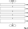
Nachfolgend wird unter Bezugnahme auf4 ein Ausführungsbeispiel des erfindungsgemäßen Verfahrens zur Ansteuerung von mindestens einem Auslöseelement für ein Personenschutzmittel beschrieben. The following is with reference to 4 An embodiment of the method according to the invention for controlling at least one triggering element for a personal protection means described.

Wie aus4 ersichtlich ist, wird in einem Schritt S100 fortlaufend ein erzeugter Zündstrom IZP detektiert und im Schritt S110 mit einem vorgegebenen ersten Schwellwert SW1 verglichen. Im Schritt S120 werden erste Phasen (RZP = ∞), in welchen der Zündstrom IZP nach Erreichen des Nominalwerts NOM den ersten Schwellwert SW1 unterschreitet, und zweite Phasen (RZP = 0Ω) bestimmt, in welchen der Zündstrom IZP nach Unterschreiten des ersten Schwellwerts SW1 den Nominalwert NOM wieder erreicht oder überschreitet. Im Schritt S130 werden die Wechsel zwischen den Zündstromphasen gezählt. Im Schritt S130 wird die Regelgeschwindigkeit erhöht, wenn die Anzahl der Wechsel zwischen den Zündstromphasen einen vorgegebenen zweiten Schwellwert erreicht oder überschreitet. Der zweite Schwellwert kann beispielsweise als Anzahl der Wechsel im Bereich von 2 bis 4 vorgegeben werden.How out 4 is apparent, in a step S100, a generated ignition current IZP is continuously detected and compared in step S110 with a predetermined first threshold value SW1. In step S120, first phases (RZP = ∞), in which the ignition current IZP falls below the first threshold value SW1 after reaching the nominal value NOM, and second phases (RZP = 0Ω) in which the ignition current IZP falls below the first threshold value SW1 again reaches or exceeds the nominal value NOM. In step S130, the changes between the ignition phases are counted. In step S130, the control speed is increased when the number of changes between the ignition phases reaches or exceeds a predetermined second threshold. The second threshold value can be specified, for example, as the number of changes in the range from 2 to 4.

Ausführungsformen der vorliegenden Erfindung stellen ein Verfahren und eine Anordnung zur Ansteuerung von mindestens einem Auslöseelement für Personenschutzmittel zur Verfügung, welche in vorteilhafter Weise Aussetzer im Zündstrom während eines Zündvorgangs erkennen und in Abhängigkeit von den erkannten Aussetzern automatisch die Eigenschaften des Zündstromregelvorgangs so verändern, dass nur noch geringfügige Zündstromüberhöhungen auftreten. Dies lässt eine Dimensionierung der Endstufenfläche auf die typischen Zündströme zu, so dass keine zusätzliche Fläche im ASIC-Baustein der Anordnung zur Ansteuerung von mindestens einem Auslöseelement für intermittierende Kurzschlüsse vorgehalten werden muss.Embodiments of the present invention provide a method and an arrangement for controlling at least one trigger element for personal protection means which advantageously detect misfires in the ignition current during an ignition process and automatically change the properties of the ignition current control process depending on the detected dropouts so that only slight Zündstromüberhöhungen occur. This allows a dimensioning of the output stage area to the typical ignition currents, so that no additional area in the ASIC module of the arrangement for controlling at least one trigger element for intermittent short circuits must be maintained.

ZITATE ENTHALTEN IN DER BESCHREIBUNG QUOTES INCLUDE IN THE DESCRIPTION

Diese Liste der vom Anmelder aufgeführten Dokumente wurde automatisiert erzeugt und ist ausschließlich zur besseren Information des Lesers aufgenommen. Die Liste ist nicht Bestandteil der deutschen Patent- bzw. Gebrauchsmusteranmeldung. Das DPMA übernimmt keinerlei Haftung für etwaige Fehler oder Auslassungen.This list of the documents listed by the applicant has been generated automatically and is included solely for the better information of the reader. The list is not part of the German patent or utility model application. The DPMA assumes no liability for any errors or omissions.

Zitierte PatentliteraturCited patent literature

  • DE 102009027918 A1[0003]DE 102009027918 A1[0003]
  • DE 102005055068 A1[0004]DE 102005055068 A1[0004]

Claims (10)

Translated fromGerman
Verfahren zur Ansteuerung von mindestens einem Auslöseelement für Personenschutzmittel, wobei über eine High-Side-Steuerschaltung (100) eine erste Verbindung von einer Energiequelle (ER) zu dem mindestens einen Auslöseelement (RZP) und über eine Low-Side-Steuerschaltung (200) eine zweite Verbindung von dem mindestens einen Auslöseelement (RZP) zur Masse herstellt werden, und wobei ein Zündstrom (IZP) für das mindestens eine Auslöseelement (RZP) nach Aktivierung eines Zündvorgangs auf einen vorgegebenen Nominalwert (NOM) geregelt wird,dadurch gekennzeichnet, dass der Zündstrom (IZP) fortlaufend detektiert und mit einem vorgegebenen ersten Schwellwert (SW1) verglichen wird, wobei erste Phasen (RZP = ∞), in welchen der Zündstrom (IZP) nach Erreichen des Nominalwerts (NOM) den ersten Schwellwert (SW1) unterschreitet, und zweite Phasen (RZP = 0Ω) bestimmt werden, in welchen der Zündstrom (IZP) nach Unterschreiten des ersten Schwellwerts (SW1) den Nominalwert (NOM) wieder erreicht oder überschreitet, und wobei die Wechsel zwischen den Zündstromphasen gezählt werden und eine Regelgeschwindigkeit erhöht wird, wenn die Anzahl der Wechsel zwischen den Zündstromphasen einen vorgegebenen zweiten Schwellwert erreicht oder überschreitet.Method for controlling at least one trigger element for personal protection means, wherein a high-side control circuit ( 100 ) a first connection from a power source (ER) to the at least one trigger element (RZP ) and via a low-side control circuit ( 200 ) A second connection of the at least one trigger element (RZP) are prepared to ground, and wherein a trigger current (IZP) for the at least one trigger element (RZP) by activating an ignition process (to a predetermined nominal value NOM) is regulated,characterized characterized in that the ignition current (IZP ) is continuously detected and compared with a predetermined first threshold (SW1), wherein first phases (RZP = ∞) in which the ignition current (IZP ) after reaching the nominal value (NOM) the first Threshold (SW1) falls below, and second phases (RZP = 0Ω) are determined in which the ignition current (IZP ) falls below the first threshold (SW1) the nominal value (NOM) again or exceeds, and wherein the changes between the Zündstromphasen be counted and a control speed is increased when the number of alternations between the Zündstromphasen reaches or exceeds a predetermined second threshold ,Verfahren nach Anspruch 1, dadurch gekennzeichnet, dass der zweite Schwellwert als Anzahl der Wechsel im Bereich von 2 bis 4 vorgegeben wird.A method according to claim 1, characterized in that the second threshold value is specified as the number of changes in the range of 2 to 4.Verfahren nach Anspruch 1 oder 2, dadurch gekennzeichnet, dass durch Auswerten des Zündstromverlaufs ein angeschlossenes Auslöseelement (RZP) erkannt wird.A method according to claim 1 or 2, characterized in that by evaluating the Zündstromverlaufs a connected trigger element (RZP ) is detected.Verfahren nach Anspruch 3, dadurch gekennzeichnet, dass bei intermittierenden Stromwerten eine Zündpille mit intermittierenden Widerstandswerten erkannt wird.A method according to claim 3, characterized in that at intermittent current values a squib with intermittent resistance values is detected.Verfahren nach Anspruch 3, dadurch gekennzeichnet, dass bei im Wesentlichen gleichbleibenden Stromwerten ein LEA-Zündkreis erkannt wird.A method according to claim 3, characterized in that at substantially constant current values, an LEA ignition circuit is detected.Anordnung zur Ansteuerung von mindestens einem Auslöseelement für Personenschutzmittel mit einer High-Side-Steuerschaltung (100), welche eine erste Verbindung von einer Energiequelle (ER) zu dem mindestens einen Auslöseelement (RZP) herstellt, einer Low-Side-Steuerschaltung (200), welche eine zweite Verbindung von dem mindestens einen Auslöseelement (RZP) zur Masse herstellt, und einer Regelanordnung (30), welche einen Zündstrom (IZP) für das mindestens eine Auslöseelement (RZP) nach Aktivierung eines Zündvorgangs auf einen vorgegebenen Nominalwert (NOM) regelt, dadurch gekennzeichnet, dass eine Auswerte- und Steuereinheit (38) den fortlaufend detektierten Zündstrom (IZP) mit einem vorgegebenen ersten Schwellwert (SW1) vergleicht und erste Phasen (RZP = ∞), in welchen der Zündstrom (IZP) nach Erreichen des Nominalwerts (NOM) den ersten Schwellwert (SW1) unterschreitet, und zweite Phasen (RZP = 0Ω) bestimmt, in welchen der Zündstrom (IZP) nach Unterschreiten des ersten Schwellwerts (SW1) den Nominalwert (NOM) wieder erreicht oder überschreitet, wobei die Auswerte- und Steuereinheit (38) die Wechsel zwischen den Zündstromphasen zählt und eine Regelgeschwindigkeit der Regelanordnung (30) erhöht, wenn die Anzahl der Wechsel zwischen den Zündstromphasen einen vorgegebenen zweiten Schwellwert erreicht oder überschreitet.Arrangement for controlling at least one triggering element for personal protective equipment with a high-side control circuit ( 100 ), which establishes a first connection from a power source (ER) to the at least one triggering element (RZP ), a low-side control circuit ( 200 ), which produces a second connection from the at least one triggering element (RZP ) to ground, and a control arrangement ( 30 ), which regulates an ignition current (IZP ) for the at least one triggering element (RZP ) after activation of an ignition process to a predetermined nominal value (NOM), characterized in that an evaluation and control unit ( 38 ) compares the continuously detected ignition current (IZP ) with a predetermined first threshold value (SW1) and first phases (RZP = ∞) in which the ignition current (IZP ) falls below the first threshold value (SW1) after reaching the nominal value (NOM) , and second phases (RZP = 0Ω) determines in which of the ignition current (IZP ) after falling below the first threshold value (SW1) again reaches or exceeds the nominal value (NOM), wherein the evaluation and control unit ( 38 ) counts the changes between the Zündstromphasen and a control speed of the control arrangement ( 30 ) is increased when the number of changes between the Zündstromphasen reaches or exceeds a predetermined second threshold.Anordnung nach Anspruch 6, dadurch gekennzeichnet, dass die Auswerteund Steuereinheit (38) den Zündstrom (IZP) über die Regelanordnung (30) und mindestens eine Endstufe (20) einstellt, wobei die mindestens eine Endstufe (20) einen Leistungstransistor (T) zum Einstellen des Zündstroms (IZP) und einen Sense-Transistor (TS) zum Einstellen eines Sense-Stroms (IS) aufweist, welcher den Zündstrom (IZP) repräsentiert, wobei ein Stromdetektor (36) den Sense-Stroms (IS) fortlaufend erfasst.Arrangement according to claim 6, characterized in that the evaluation and control unit ( 38 ) the ignition current (IZP ) via the control arrangement ( 30 ) and at least one final stage ( 20 ), wherein the at least one output stage ( 20 ) comprises a power transistor (T) for adjusting the ignition current (IZP ) and a sense transistor (TS ) for setting a sense current (IS ), which represents the ignition current (IZP ), wherein a current detector ( 36 ) continuously detects the sense current (IS ).Anordnung nach Anspruch 7, dadurch gekennzeichnet, dass die Regelanordnung (30) eine Stromquelle (32), welche einen Referenzstrom (IR) erzeugt, und einen Regler (R1) aufweist, wobei die Auswerte- und Steuereinheit (38) die Stromquelle (32) und den Regler (R1) aktiviert, wobei der Regler (R1) den Referenzstrom (IR) mit dem Sense-Strom (IS) vergleicht, welcher den erfassten Zündstrom (IZP) repräsentiert, wobei der Regler in Abhängigkeit des Vergleichs einen Steuereingang der Endstufe (20) auflädt und den Zündstrom (IZP) über den Leistungstransistor (T) auf den Nominalwert (NOM) regelt.Arrangement according to claim 7, characterized in that the control arrangement ( 30 ) a power source ( 32 ), which generates a reference current (IR ), and a regulator (R1), wherein the evaluation and control unit ( 38 ) the power source ( 32 ) and the controller (R1) is activated, wherein the controller (R1) compares the reference current (IR ) with the sense current (IS ) representing the detected ignition current (IZP ), the controller depending on the comparison Control input of the power amplifier ( 20 ) and controls the ignition current (IZP ) via the power transistor (T) to the nominal value (NOM).Anordnung nach Anspruch 7 oder 8, dadurch gekennzeichnet, dass die Regelanordnung (30) eine Stromsenke (34) aufweist, wobei die Auswerte- und Steuereinheit (38) die Stromsenke (34) aktiviert, welche die Ladung am Steuereingang der Endstufe (20) abbaut und den Regelvorgang beschleunigt.Arrangement according to claim 7 or 8, characterized in that the control arrangement ( 30 ) a current sink ( 34 ), wherein the evaluation and control unit ( 38 ) the current sink ( 34 ) which activates the charge at the control input of the power amplifier ( 20 ) degrades and accelerates the control process.Anordnung nach Anspruch 9, dadurch gekennzeichnet, dass die Auswerteund Steuereinheit (38) die Stromsenke (34) aktiviert, wenn die Anzahl der Wechsel zwischen den Zündstromphasen den vorgegebenen zweiten Schwellwert erreicht oder überschreitet.Arrangement according to claim 9, characterized in that the evaluation and control unit ( 38 ) the current sink ( 34 ) is activated when the number of changes between the Zündstromphasen reaches or exceeds the predetermined second threshold.
DE2012102009552012-01-242012-01-24 Method and arrangement for controlling at least one triggering element for personal protective equipmentWithdrawnDE102012200955A1 (en)

Priority Applications (8)

Application NumberPriority DateFiling DateTitle
DE201210200955DE102012200955A1 (en)2012-01-242012-01-24 Method and arrangement for controlling at least one triggering element for personal protective equipment
PCT/EP2013/050554WO2013110519A1 (en)2012-01-242013-01-14Method and arrangement for actuating at least one triggering element for a personal protection means
JP2014552590AJP5941997B2 (en)2012-01-242013-01-14 Method and apparatus for controlling at least one trigger member for personnel protection means
KR1020147020645AKR101953424B1 (en)2012-01-242013-01-14Method and arrangement for actuating at least one triggering element for a personal protection means
EP13700682.1AEP2807056B1 (en)2012-01-242013-01-14Method and arrangement for actuating at least one triggering element for a personal protection means
US14/374,200US9227586B2 (en)2012-01-242013-01-14Method and system for controlling at least one triggering element for passenger protection means
CN201380006312.7ACN104254466B (en)2012-01-242013-01-14For the method and apparatus controlling at least one trigger element for personal protection means
TW102102286ATWI579169B (en)2012-01-242013-01-22Process and device to control at least an actuating element for person protecting means

Applications Claiming Priority (1)

Application NumberPriority DateFiling DateTitle
DE201210200955DE102012200955A1 (en)2012-01-242012-01-24 Method and arrangement for controlling at least one triggering element for personal protective equipment

Publications (1)

Publication NumberPublication Date
DE102012200955A1true DE102012200955A1 (en)2013-07-25

Family

ID=47594697

Family Applications (1)

Application NumberTitlePriority DateFiling Date
DE201210200955WithdrawnDE102012200955A1 (en)2012-01-242012-01-24 Method and arrangement for controlling at least one triggering element for personal protective equipment

Country Status (8)

CountryLink
US (1)US9227586B2 (en)
EP (1)EP2807056B1 (en)
JP (1)JP5941997B2 (en)
KR (1)KR101953424B1 (en)
CN (1)CN104254466B (en)
DE (1)DE102012200955A1 (en)
TW (1)TWI579169B (en)
WO (1)WO2013110519A1 (en)

Families Citing this family (1)

* Cited by examiner, † Cited by third party
Publication numberPriority datePublication dateAssigneeTitle
WO2020257179A1 (en)2019-06-202020-12-24Conocophillips CompanyWater injection into a hydrocarbon reservoir

Citations (2)

* Cited by examiner, † Cited by third party
Publication numberPriority datePublication dateAssigneeTitle
DE102005055068A1 (en)2005-11-182007-05-24Robert Bosch GmbhIgnition units e.g. high-side circuit breaker, controlling device, has comparison units releasing high-side-circuit breaker for ignition time, where one of operational amplifier and ignition electricity meters adjust trigger circuit
DE102009027918A1 (en)2009-07-222011-01-27Robert Bosch Gmbh Arrangement and method for controlling at least one triggering element for a personal protection device

Family Cites Families (10)

* Cited by examiner, † Cited by third party
Publication numberPriority datePublication dateAssigneeTitle
DE19622685C2 (en)*1995-12-122003-06-12Siemens Ag Arrangement for triggering a restraint in a motor vehicle
DE19638457C1 (en)*1996-09-191998-01-22Siemens AgCurrent limiting circuit for triggering safety system, esp. motor vehicle airbag control system
DE19732677A1 (en)*1997-07-291999-03-04Siemens Ag Arrangement and method for testing a circuit device which is provided for controlling an occupant protection device of a motor vehicle
DE19749856B4 (en)*1997-11-112004-06-09Siemens Ag Method and ignition circuit for triggering an occupant protection system
DE19826704C1 (en)1998-06-162000-02-10Siemens Ag Device for igniting an ignition element of a motor vehicle occupant protection device
JP4381076B2 (en)*2003-09-172009-12-09富士通テン株式会社 Airbag ignition circuit and airbag ignition device
DE102004010135B4 (en)*2004-02-272013-11-07Robert Bosch Gmbh Device for energizing at least one ignition output by means of an ignition current from an energy reserve
DE102005045022A1 (en)*2005-09-212007-03-29Robert Bosch Gmbh Control device for controlling personal protective equipment
CN101674960B (en)*2007-05-112013-08-21飞思卡尔半导体公司Digital squib driver circuit
DE102007039835A1 (en)*2007-08-232009-02-26Robert Bosch Gmbh Control unit and method for controlling personal protective equipment for a vehicle

Patent Citations (2)

* Cited by examiner, † Cited by third party
Publication numberPriority datePublication dateAssigneeTitle
DE102005055068A1 (en)2005-11-182007-05-24Robert Bosch GmbhIgnition units e.g. high-side circuit breaker, controlling device, has comparison units releasing high-side-circuit breaker for ignition time, where one of operational amplifier and ignition electricity meters adjust trigger circuit
DE102009027918A1 (en)2009-07-222011-01-27Robert Bosch Gmbh Arrangement and method for controlling at least one triggering element for a personal protection device

Also Published As

Publication numberPublication date
TW201350370A (en)2013-12-16
CN104254466A (en)2014-12-31
CN104254466B (en)2016-06-29
JP5941997B2 (en)2016-06-29
WO2013110519A1 (en)2013-08-01
EP2807056A1 (en)2014-12-03
TWI579169B (en)2017-04-21
JP2015507578A (en)2015-03-12
EP2807056B1 (en)2015-12-09
US9227586B2 (en)2016-01-05
KR101953424B1 (en)2019-05-31
US20140371993A1 (en)2014-12-18
KR20140115330A (en)2014-09-30

Similar Documents

PublicationPublication DateTitle
DE102006054354B4 (en) Self-protective Crowbar
EP2250051B1 (en)Control unit and method for activating personal protection means
DE102012201049A1 (en) Method and device for detecting a usability of a drive device
DE102013224106A1 (en) Surge protection for motor vehicle electrical system with load shedding
DE3233536A1 (en) DEVICE FOR THE CLOCKED REGULATION OF A COIL FLOWING THROUGH
EP0927117B1 (en)Circuit arrangement for limiting current in a protective system, in particular an airbag-control system
DE112014004562T5 (en) Device for controlling a consumer, vehicle air conditioning and load circuit for short-circuit protection
DE102012210874A1 (en) Method for detecting, for diagnosing and triggering a triggering device for a passenger protection device for a vehicle and device for detecting and triggering a triggering device for a personal protection device
EP1062131B1 (en)Method for operating an occupant safety device, and a control unit
EP2782793B1 (en)Method and assembly for controlling at least one triggering element for a personal protective means
EP2807056B1 (en)Method and arrangement for actuating at least one triggering element for a personal protection means
DE102008043233A1 (en) Device for energizing an ignition output
DE19811269C1 (en)Electronic circuit with protective circuit for lubrication controllers in motor vehicles, esp. lorries
DE102009047480B4 (en) Control device and method for controlling personal protection devices for a vehicle
EP0965501A2 (en)Apparatus for igniting the squib of a vehicle passive restraint system
DE102009027918A1 (en) Arrangement and method for controlling at least one triggering element for a personal protection device
DE102005008905A1 (en)Trigger circuit for detonator of passenger protection device released by at least one DC-voltage impulse
DE10101978B4 (en) Circuit arrangement for controlling a load
EP3003790B1 (en)Electronic airbag ignition circuit with variable turn-on current duration
DE102014219048A1 (en) Apparatus and method for determining a short circuit across a load
DE102006047379B4 (en) Device and method for energizing a Zündkreisschaltung for personal protection
EP2795760B1 (en)Charging circuit for a capacitance and method for charging a capacitance
DE1220483B (en) Circuit arrangement for regulated amplifiers
DE10125812A1 (en)Actuator for triggering a safety device in a motor vehicle accident operates through a magnetic coil on a low-loss hybrid capacitor irrespective of the motor vehicle's battery
DE102016216394B4 (en) INJECTION CONTROL DEVICE

Legal Events

DateCodeTitleDescription
R005Application deemed withdrawn due to failure to request examination

[8]ページ先頭

©2009-2025 Movatter.jp