DE102012112716A1 - Medical support arm - Google Patents
Medical support armDownload PDFInfo
- Publication number
- DE102012112716A1 DE102012112716A1DE102012112716.6ADE102012112716ADE102012112716A1DE 102012112716 A1DE102012112716 A1DE 102012112716A1DE 102012112716 ADE102012112716 ADE 102012112716ADE 102012112716 A1DE102012112716 A1DE 102012112716A1
- Authority
- DE
- Germany
- Prior art keywords
- locking
- pins
- joint
- holding arm
- recesses
- Prior art date
- Legal status (The legal status is an assumption and is not a legal conclusion. Google has not performed a legal analysis and makes no representation as to the accuracy of the status listed.)
- Withdrawn
Links
- 238000007654immersionMethods0.000description3
- 238000004519manufacturing processMethods0.000description2
- BUHVIAUBTBOHAG-FOYDDCNASA-N(2r,3r,4s,5r)-2-[6-[[2-(3,5-dimethoxyphenyl)-2-(2-methylphenyl)ethyl]amino]purin-9-yl]-5-(hydroxymethyl)oxolane-3,4-diolChemical compoundCOC1=CC(OC)=CC(C(CNC=2C=3N=CN(C=3N=CN=2)[C@H]2[C@@H]([C@H](O)[C@@H](CO)O2)O)C=2C(=CC=CC=2)C)=C1BUHVIAUBTBOHAG-FOYDDCNASA-N0.000description1
- 230000001419dependent effectEffects0.000description1
- 230000005489elastic deformationEffects0.000description1
- 230000008092positive effectEffects0.000description1
- 238000007493shaping processMethods0.000description1
- 239000002689soilSubstances0.000description1
- 230000003068static effectEffects0.000description1
Images

Classifications
- F—MECHANICAL ENGINEERING; LIGHTING; HEATING; WEAPONS; BLASTING
- F16—ENGINEERING ELEMENTS AND UNITS; GENERAL MEASURES FOR PRODUCING AND MAINTAINING EFFECTIVE FUNCTIONING OF MACHINES OR INSTALLATIONS; THERMAL INSULATION IN GENERAL
- F16M—FRAMES, CASINGS OR BEDS OF ENGINES, MACHINES OR APPARATUS, NOT SPECIFIC TO ENGINES, MACHINES OR APPARATUS PROVIDED FOR ELSEWHERE; STANDS; SUPPORTS
- F16M13/00—Other supports for positioning apparatus or articles; Means for steadying hand-held apparatus or articles
- F16M13/02—Other supports for positioning apparatus or articles; Means for steadying hand-held apparatus or articles for supporting on, or attaching to, an object, e.g. tree, gate, window-frame, cycle
- F16M13/022—Other supports for positioning apparatus or articles; Means for steadying hand-held apparatus or articles for supporting on, or attaching to, an object, e.g. tree, gate, window-frame, cycle repositionable
- A—HUMAN NECESSITIES
- A61—MEDICAL OR VETERINARY SCIENCE; HYGIENE
- A61B—DIAGNOSIS; SURGERY; IDENTIFICATION
- A61B17/00—Surgical instruments, devices or methods
- A—HUMAN NECESSITIES
- A61—MEDICAL OR VETERINARY SCIENCE; HYGIENE
- A61B—DIAGNOSIS; SURGERY; IDENTIFICATION
- A61B90/00—Instruments, implements or accessories specially adapted for surgery or diagnosis and not covered by any of the groups A61B1/00 - A61B50/00, e.g. for luxation treatment or for protecting wound edges
- A61B90/50—Supports for surgical instruments, e.g. articulated arms
- F—MECHANICAL ENGINEERING; LIGHTING; HEATING; WEAPONS; BLASTING
- F16—ENGINEERING ELEMENTS AND UNITS; GENERAL MEASURES FOR PRODUCING AND MAINTAINING EFFECTIVE FUNCTIONING OF MACHINES OR INSTALLATIONS; THERMAL INSULATION IN GENERAL
- F16B—DEVICES FOR FASTENING OR SECURING CONSTRUCTIONAL ELEMENTS OR MACHINE PARTS TOGETHER, e.g. NAILS, BOLTS, CIRCLIPS, CLAMPS, CLIPS OR WEDGES; JOINTS OR JOINTING
- F16B21/00—Means for preventing relative axial movement of a pin, spigot, shaft or the like and a member surrounding it; Stud-and-socket releasable fastenings
- F16B21/10—Means for preventing relative axial movement of a pin, spigot, shaft or the like and a member surrounding it; Stud-and-socket releasable fastenings by separate parts
- F16B21/20—Means for preventing relative axial movement of a pin, spigot, shaft or the like and a member surrounding it; Stud-and-socket releasable fastenings by separate parts for bolts or shafts without holes, grooves, or notches for locking members
- F—MECHANICAL ENGINEERING; LIGHTING; HEATING; WEAPONS; BLASTING
- F16—ENGINEERING ELEMENTS AND UNITS; GENERAL MEASURES FOR PRODUCING AND MAINTAINING EFFECTIVE FUNCTIONING OF MACHINES OR INSTALLATIONS; THERMAL INSULATION IN GENERAL
- F16B—DEVICES FOR FASTENING OR SECURING CONSTRUCTIONAL ELEMENTS OR MACHINE PARTS TOGETHER, e.g. NAILS, BOLTS, CIRCLIPS, CLAMPS, CLIPS OR WEDGES; JOINTS OR JOINTING
- F16B7/00—Connections of rods or tubes, e.g. of non-circular section, mutually, including resilient connections
- F16B7/04—Clamping or clipping connections
- F16B7/0433—Clamping or clipping connections for rods or tubes being in parallel relationship
- F—MECHANICAL ENGINEERING; LIGHTING; HEATING; WEAPONS; BLASTING
- F16—ENGINEERING ELEMENTS AND UNITS; GENERAL MEASURES FOR PRODUCING AND MAINTAINING EFFECTIVE FUNCTIONING OF MACHINES OR INSTALLATIONS; THERMAL INSULATION IN GENERAL
- F16B—DEVICES FOR FASTENING OR SECURING CONSTRUCTIONAL ELEMENTS OR MACHINE PARTS TOGETHER, e.g. NAILS, BOLTS, CIRCLIPS, CLAMPS, CLIPS OR WEDGES; JOINTS OR JOINTING
- F16B9/00—Connections of rods or tubular parts to flat surfaces at an angle
- F16B9/07—Connections of rods or tubular parts to flat surfaces at an angle involving plastic or elastic deformation when assembling
- F—MECHANICAL ENGINEERING; LIGHTING; HEATING; WEAPONS; BLASTING
- F16—ENGINEERING ELEMENTS AND UNITS; GENERAL MEASURES FOR PRODUCING AND MAINTAINING EFFECTIVE FUNCTIONING OF MACHINES OR INSTALLATIONS; THERMAL INSULATION IN GENERAL
- F16C—SHAFTS; FLEXIBLE SHAFTS; ELEMENTS OR CRANKSHAFT MECHANISMS; ROTARY BODIES OTHER THAN GEARING ELEMENTS; BEARINGS
- F16C11/00—Pivots; Pivotal connections
- F16C11/04—Pivotal connections
- F16C11/10—Arrangements for locking
- F—MECHANICAL ENGINEERING; LIGHTING; HEATING; WEAPONS; BLASTING
- F16—ENGINEERING ELEMENTS AND UNITS; GENERAL MEASURES FOR PRODUCING AND MAINTAINING EFFECTIVE FUNCTIONING OF MACHINES OR INSTALLATIONS; THERMAL INSULATION IN GENERAL
- F16D—COUPLINGS FOR TRANSMITTING ROTATION; CLUTCHES; BRAKES
- F16D1/00—Couplings for rigidly connecting two coaxial shafts or other movable machine elements
- F16D1/12—Couplings for rigidly connecting two coaxial shafts or other movable machine elements allowing adjustment of the parts about the axis
- F—MECHANICAL ENGINEERING; LIGHTING; HEATING; WEAPONS; BLASTING
- F16—ENGINEERING ELEMENTS AND UNITS; GENERAL MEASURES FOR PRODUCING AND MAINTAINING EFFECTIVE FUNCTIONING OF MACHINES OR INSTALLATIONS; THERMAL INSULATION IN GENERAL
- F16M—FRAMES, CASINGS OR BEDS OF ENGINES, MACHINES OR APPARATUS, NOT SPECIFIC TO ENGINES, MACHINES OR APPARATUS PROVIDED FOR ELSEWHERE; STANDS; SUPPORTS
- F16M11/00—Stands or trestles as supports for apparatus or articles placed thereon ; Stands for scientific apparatus such as gravitational force meters
- F16M11/02—Heads
- F16M11/04—Means for attachment of apparatus; Means allowing adjustment of the apparatus relatively to the stand
- F16M11/06—Means for attachment of apparatus; Means allowing adjustment of the apparatus relatively to the stand allowing pivoting
- F—MECHANICAL ENGINEERING; LIGHTING; HEATING; WEAPONS; BLASTING
- F16—ENGINEERING ELEMENTS AND UNITS; GENERAL MEASURES FOR PRODUCING AND MAINTAINING EFFECTIVE FUNCTIONING OF MACHINES OR INSTALLATIONS; THERMAL INSULATION IN GENERAL
- F16M—FRAMES, CASINGS OR BEDS OF ENGINES, MACHINES OR APPARATUS, NOT SPECIFIC TO ENGINES, MACHINES OR APPARATUS PROVIDED FOR ELSEWHERE; STANDS; SUPPORTS
- F16M11/00—Stands or trestles as supports for apparatus or articles placed thereon ; Stands for scientific apparatus such as gravitational force meters
- F16M11/20—Undercarriages with or without wheels
- F16M11/2007—Undercarriages with or without wheels comprising means allowing pivoting adjustment
- A—HUMAN NECESSITIES
- A61—MEDICAL OR VETERINARY SCIENCE; HYGIENE
- A61B—DIAGNOSIS; SURGERY; IDENTIFICATION
- A61B90/00—Instruments, implements or accessories specially adapted for surgery or diagnosis and not covered by any of the groups A61B1/00 - A61B50/00, e.g. for luxation treatment or for protecting wound edges
- A61B90/50—Supports for surgical instruments, e.g. articulated arms
- A61B2090/508—Supports for surgical instruments, e.g. articulated arms with releasable brake mechanisms
- F—MECHANICAL ENGINEERING; LIGHTING; HEATING; WEAPONS; BLASTING
- F16—ENGINEERING ELEMENTS AND UNITS; GENERAL MEASURES FOR PRODUCING AND MAINTAINING EFFECTIVE FUNCTIONING OF MACHINES OR INSTALLATIONS; THERMAL INSULATION IN GENERAL
- F16B—DEVICES FOR FASTENING OR SECURING CONSTRUCTIONAL ELEMENTS OR MACHINE PARTS TOGETHER, e.g. NAILS, BOLTS, CIRCLIPS, CLAMPS, CLIPS OR WEDGES; JOINTS OR JOINTING
- F16B2200/00—Constructional details of connections not covered for in other groups of this subclass
- F16B2200/50—Flanged connections
- F—MECHANICAL ENGINEERING; LIGHTING; HEATING; WEAPONS; BLASTING
- F16—ENGINEERING ELEMENTS AND UNITS; GENERAL MEASURES FOR PRODUCING AND MAINTAINING EFFECTIVE FUNCTIONING OF MACHINES OR INSTALLATIONS; THERMAL INSULATION IN GENERAL
- F16B—DEVICES FOR FASTENING OR SECURING CONSTRUCTIONAL ELEMENTS OR MACHINE PARTS TOGETHER, e.g. NAILS, BOLTS, CIRCLIPS, CLAMPS, CLIPS OR WEDGES; JOINTS OR JOINTING
- F16B7/00—Connections of rods or tubes, e.g. of non-circular section, mutually, including resilient connections
- F16B7/02—Connections of rods or tubes, e.g. of non-circular section, mutually, including resilient connections with conical parts
- F—MECHANICAL ENGINEERING; LIGHTING; HEATING; WEAPONS; BLASTING
- F16—ENGINEERING ELEMENTS AND UNITS; GENERAL MEASURES FOR PRODUCING AND MAINTAINING EFFECTIVE FUNCTIONING OF MACHINES OR INSTALLATIONS; THERMAL INSULATION IN GENERAL
- F16D—COUPLINGS FOR TRANSMITTING ROTATION; CLUTCHES; BRAKES
- F16D11/00—Clutches in which the members have interengaging parts
- F16D11/14—Clutches in which the members have interengaging parts with clutching members movable only axially
- F—MECHANICAL ENGINEERING; LIGHTING; HEATING; WEAPONS; BLASTING
- F16—ENGINEERING ELEMENTS AND UNITS; GENERAL MEASURES FOR PRODUCING AND MAINTAINING EFFECTIVE FUNCTIONING OF MACHINES OR INSTALLATIONS; THERMAL INSULATION IN GENERAL
- F16M—FRAMES, CASINGS OR BEDS OF ENGINES, MACHINES OR APPARATUS, NOT SPECIFIC TO ENGINES, MACHINES OR APPARATUS PROVIDED FOR ELSEWHERE; STANDS; SUPPORTS
- F16M2200/00—Details of stands or supports
- F16M2200/02—Locking means
- F16M2200/021—Locking means for rotational movement
- F16M2200/024—Locking means for rotational movement by positive interaction, e.g. male-female connections
- F—MECHANICAL ENGINEERING; LIGHTING; HEATING; WEAPONS; BLASTING
- F16—ENGINEERING ELEMENTS AND UNITS; GENERAL MEASURES FOR PRODUCING AND MAINTAINING EFFECTIVE FUNCTIONING OF MACHINES OR INSTALLATIONS; THERMAL INSULATION IN GENERAL
- F16M—FRAMES, CASINGS OR BEDS OF ENGINES, MACHINES OR APPARATUS, NOT SPECIFIC TO ENGINES, MACHINES OR APPARATUS PROVIDED FOR ELSEWHERE; STANDS; SUPPORTS
- F16M2200/00—Details of stands or supports
- F16M2200/06—Arms
- F16M2200/065—Arms with a special structure, e.g. reinforced or adapted for space reduction
- Y—GENERAL TAGGING OF NEW TECHNOLOGICAL DEVELOPMENTS; GENERAL TAGGING OF CROSS-SECTIONAL TECHNOLOGIES SPANNING OVER SEVERAL SECTIONS OF THE IPC; TECHNICAL SUBJECTS COVERED BY FORMER USPC CROSS-REFERENCE ART COLLECTIONS [XRACs] AND DIGESTS
- Y10—TECHNICAL SUBJECTS COVERED BY FORMER USPC
- Y10T—TECHNICAL SUBJECTS COVERED BY FORMER US CLASSIFICATION
- Y10T403/00—Joints and connections
- Y10T403/32—Articulated members
- Y10T403/32254—Lockable at fixed position
- Y10T403/32262—At selected angle
- Y10T403/32418—Plural distinct positions
- Y—GENERAL TAGGING OF NEW TECHNOLOGICAL DEVELOPMENTS; GENERAL TAGGING OF CROSS-SECTIONAL TECHNOLOGIES SPANNING OVER SEVERAL SECTIONS OF THE IPC; TECHNICAL SUBJECTS COVERED BY FORMER USPC CROSS-REFERENCE ART COLLECTIONS [XRACs] AND DIGESTS
- Y10—TECHNICAL SUBJECTS COVERED BY FORMER USPC
- Y10T—TECHNICAL SUBJECTS COVERED BY FORMER US CLASSIFICATION
- Y10T403/00—Joints and connections
- Y10T403/32—Articulated members
- Y10T403/32549—Articulated members including limit means
- Y10T403/32557—Articulated members including limit means for pivotal motion
- Y10T403/32581—Pin and slot
Landscapes
- Engineering & Computer Science (AREA)
- General Engineering & Computer Science (AREA)
- Mechanical Engineering (AREA)
- Health & Medical Sciences (AREA)
- Surgery (AREA)
- Life Sciences & Earth Sciences (AREA)
- Public Health (AREA)
- Animal Behavior & Ethology (AREA)
- Veterinary Medicine (AREA)
- Biomedical Technology (AREA)
- Heart & Thoracic Surgery (AREA)
- Medical Informatics (AREA)
- Molecular Biology (AREA)
- Nuclear Medicine, Radiotherapy & Molecular Imaging (AREA)
- General Health & Medical Sciences (AREA)
- Pathology (AREA)
- Oral & Maxillofacial Surgery (AREA)
- Accommodation For Nursing Or Treatment Tables (AREA)
- Prostheses (AREA)
- Quick-Acting Or Multi-Walled Pipe Joints (AREA)
- Pivots And Pivotal Connections (AREA)
- Infusion, Injection, And Reservoir Apparatuses (AREA)
Abstract
Translated fromGermanDescription
Translated fromGermanDie Erfindung betrifft einen medizinischen Haltearm nach dem Oberbegriff des Anspruchs 1.The invention relates to a medical holding arm according to the preamble of claim 1.
Für chirurgische Anwendungen kommen heutzutage vermehrt Assistenzsysteme zum Einsatz die einen Haltearm beinhalten, der beispielsweise an der Gleitschiene eine OP-Tisches anbringbar ist. Ein solcher Haltearm wird beispielsweise bei Schulteroperationen zur Armlagerung eingesetzt. Er weist mehrere starre Halteglieder auf, die über Gelenke beweglich miteinander gekoppelt sind. Dadurch lässt sich der Haltearm frei in allen Raumrichtungen bewegen und sicher in der gewünschten Position fixieren.For surgical applications nowadays increasingly assistance systems are used which include a holding arm, which, for example, can be attached to the slide rail of an operating table. Such a support arm is used, for example, in shoulder operations for arm storage. It has a plurality of rigid support members, which are coupled to each other via joints movable. This allows the arm to move freely in all directions and to securely fix in the desired position.
Die Gelenke, die jeweils zwei starre Halteglieder des Haltearms frei beweglich miteinander koppeln, weisen einen ersten Gelenkkörper, der mit dem einen Halteglied, und eine zweiten Gelenkkörper auf, der mit dem anderen Halteglied verbunden ist. Um die beiden Halteglieder in einer gewünschten Anordnung zueinander zu fixieren, müssen die beiden Gelenkkörper gegeneinander verriegelt werden.The joints, each of which couples two rigid support members of the support arm freely movable with each other, have a first joint body, which with the one holding member, and a second joint body, which is connected to the other holding member. In order to fix the two holding members in a desired arrangement to each other, the two joint bodies must be locked against each other.
Eine Möglichkeit für eine solche Verriegelung ist in der
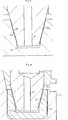
Um diese Art des Ineinandergreifens der Raststifte in die Rastvertiefungen zu ermöglichen, weisen die Raststifte jeweils einen Eingriffsteil auf, der die Form eines Kegelstumpfs hat. Die Rastvertiefungen sind entsprechend kegelstumpfförmig verjüngt. Dadurch ist sichergestellt, dass im verriegelten Zustand des Gelenks derjenige Raststift, der vollständig in die zugehörige Rastvertiefung taucht, mit seinem Eingriffsteil vollflächig in der Rastvertiefung anliegt. Demgegenüber haben die Eingriffsteile derjenigen Raststifte, die nur teilweise in die den zugehörigen Rastvertiefungen tauchen, lediglich einen Linienkontakt oder zumindest einen sehr geringen Flächenkontakt mit den zugehörigen Rastvertiefungen.In order to enable this type of engagement of the locking pins in the locking recesses, the locking pins each have an engagement part which has the shape of a truncated cone. The locking recesses are tapered in accordance frustoconical. This ensures that in the locked state of the joint of that detent pin which dives completely into the associated detent recess, with its engaging part over the entire surface in the detent recess. In contrast, the engagement parts of those locking pins that only partially dive into the associated locking recesses, only a line contact or at least a very small surface contact with the associated locking recesses.
In der praktischen Anwendung hat sicher herausgestellt, dass ein Haltearm, der mit einer Verriegelung vorstehend erläuterter Art arbeitet, im Hinblick auf hohe Lastanwendungen gewissen Beschränkungen unterliegt. So muss der Haltearm mittels eines Handgriffs, der mit einer auf die Gelenke wirkenden Entriegelungsmechanik gekoppelt ist, betätigt werden, um die Gelenke zu entriegeln. Je größer die Last ist, desto mehr Handkraft muss ausgeübt werden.In practical application, it has certainly been found that a retaining arm which operates with a lock of the type described above is subject to certain limitations with regard to high load applications. Thus, the support arm must be operated by means of a handle, which is coupled with an unlocking mechanism acting on the joints, to unlock the joints. The greater the load, the more manual power must be exercised.
Aufgabe der Erfindung ist es, ein Haltearm vorstehend beschriebener Art so weiterzubilden, dass höhere Lastanwendungen vom Benutzer bequem gehandhabt werden können.The object of the invention is to develop a holding arm of the type described above so that higher load applications can be handled comfortably by the user.
Die Erfindung löst diese Aufgabe durch einen Haltearm mit den Merkmalen des Anspruchs 1.The invention solves this problem by a holding arm with the features of claim 1.
Erfindungsgemäß hat der Eingriffsteil des jeweiligen Raststiftes mindestens eine erste abgeflachte Anlagefläche. Entsprechend hat auch die jeweilige Rastvertiefung mindestens eine zweite abgeflachte Anlagefläche. Bei Aufnahme des Eingriffsteils des Raststifts in der Rastvertiefung sind die erste und die zweite Anlagefläche zumindest zum Teil in flächigem Kontakt miteinander.According to the invention, the engagement part of the respective latching pin has at least one first flattened contact surface. Accordingly, the respective detent recess at least a second flattened contact surface. When receiving the engagement part of the latching pin in the latching recess, the first and the second contact surface are at least partially in surface contact with each other.
Unter der erfindungsgemäßen Abflachung der ersten bzw. der zweiten Anlagefläche ist zu verstehen, dass die jeweilige Anlagefläche zumindest weniger stark gewölbt ist als die restliche, vorzugsweise konische Oberfläche des Eingriffsteils des Raststifts bzw. der Rastvertiefung. Dadurch ist insbesondere auch dann, wenn der Eingriffsteil des jeweiligen Raststifts nur teilweise in die zugehörige Rastvertiefung taucht, im Bereich der beiden Anlageflächen für einen flächigen Kontakt zwischen Raststift und Rastvertiefung gesorgt ist. Dadurch sind höhere Lastanwendungen möglich als bei dem in der
Durch die erfindungsgemäße Formgebung wird also erreicht, dass die im Eingriff befindlichen Komponenten, nämlich der Eingriffsteil des Raststifts und die Rastvertiefung, stets, also insbesondere auch bei geringer Eintauchtiefe, einen flächigen Kontakt miteinander haben, wodurch die Flächenpressung zwischen diesen Komponenten reduziert wird. Infolge des geringeren Losbrechmoments, das durch die geringere elastische Verformung und das Fehlen von Kaltverschweißungseffekten bedingt ist, lässt sich das verriegelte Gelenk mit wesentlich geringerer Handkraft als bisher lösen. Besonders positiv wirkt sich dies bei nur teilweise in die Rastvertiefung eingreifendem Raststift aus. Außerdem ergibt sich eine höhere Verschleißfestigkeit an den Kanten des jeweiligen Raststifts.As a result of the shaping according to the invention, it is thus achieved that the components in engagement, namely the engagement part of the detent pin and the detent recess, always have a planar contact with each other, that is to say in particular even at a low immersion depth, whereby the surface pressure between these components is reduced. Due to the lower breakaway torque, which is due to the lower elastic deformation and the lack of Kaltverschweißungseffekten, the locked joint can be solved with much less manual force than before. This has a particularly positive effect when the detent pin engages only partially in the detent recess. In addition, there is a higher wear resistance at the edges of the respective latching pin.
Die höhere Belastungsfähigkeit macht den erfindungsgemäßen Haltearm für andere Anwendungen als bisher einsetzbar, insbesondere in hochbelasteten und dynamischen Anwendungsbereichen, z. B. Beinanwendungen, Körperstützen und dergleichen. Auch ist der Haltearm nun auch gegenüber Impulsbelastungen unempfindlich, wie sie beispielsweise beim Einschlagen von Prothesen auftreten. The higher load capacity makes the arm according to the invention for other applications than previously used, especially in highly loaded and dynamic applications, eg. Leg applications, body supports and the like. Also, the support arm is now insensitive to impulse loads, as they occur for example when knocking prostheses.
Vorzugsweise sind die erste und die zweite Anlagefläche jeweils aus einer ebenen Fläche gebildet. Solch ebene Anlageflächen ermöglichen besonders zuverlässig den gewünschten flächigen Kontakt eines nicht vollständig in die zugehörige Rastvertiefung eingreifenden Raststifts, um so die Flächenpressung zu verringern. Es ist jedoch darauf hinzuweisen, dass die Anlageflächen zur Verringerung des Flächenpressung nicht streng eben geformt sein müssen. Auch leicht gewölbte Anlageflächen kommen in Betracht, sofern sie geeignet sind, für den gewünschten flächigen Kontakt zu sorgen.Preferably, the first and the second abutment surface are each formed from a flat surface. Such flat bearing surfaces allow the desired surface contact of a not fully engaging in the associated detent recess locking pin particularly reliable, so as to reduce the surface pressure. It should be noted, however, that the abutment surfaces need not be strictly planar to reduce surface pressure. Even slightly curved contact surfaces come into consideration, provided they are suitable to provide the desired surface contact.
In einer besonders bevorzugten Ausgestaltung ist die jeweilige Rastvertiefung als Pyramidenstumpf geformt, wobei die zweite Anlagefläche aus einer Seitenfläche der so geformten Rastvertiefung gebildet ist. Der Pyramidenstumpf weist dabei beispielsweise eine rechteckige Grundfläche auf. Diese Ausgestaltung ist jedoch nur beispielhaft zu verstehen. So kann die jeweilige Rastvertiefung auch eine andere Form aufweisen, z. B. die Form eines Langlochs mit zwei einander gegenüberliegenden parallelen Seitenflächen und zwei einander gegenüberliegenden schräg zulaufenden Seitenflächen.In a particularly preferred embodiment, the respective detent recess is formed as a truncated pyramid, wherein the second abutment surface is formed from a side surface of the locking recess thus formed. The truncated pyramid has, for example, a rectangular base. However, this embodiment is only to be understood as an example. Thus, the respective detent recess may also have a different shape, for. B. the shape of a slot with two opposite parallel side surfaces and two opposing tapered side surfaces.
In einer besonders bevorzugten Ausführung ist der Pyramidenstumpf so groß bemessen, dass der Eingriffsteil des jeweiligen Raststifts bei vollständigem Eingriff nur im Bereich seiner Anlagefläche in Kontakt mit der Rastvertiefung ist. So wird jeder Linienkontakt zwischen Raststift und Rastvertiefung, der eine nachteilig hohe Flächenpressung verursacht, vermieden.In a particularly preferred embodiment, the truncated pyramid is dimensioned so large that the engagement part of the respective detent pin is in complete engagement only in the region of its contact surface in contact with the detent recess. Thus, any line contact between locking pin and locking recess, which causes a disadvantageous high surface pressure, avoided.
Vorzugsweise beinhaltet die mindestens eine erste Anlagefläche des jeweiligen Raststifts mindestens zwei Anlageflächen, die auf diametral entgegengesetzten Seiten des Eingriffsteils des Raststifts angeordnet sind. In diesem Fall weist auch die jeweilige Rastvertiefung vorzugsweise zwei diametral angeordnete zweite Anlageflächen auf. In Abhängigkeit der Drehstellung der beiden Gelenkplatten ist auf diese Weise dafür gesorgt, dass sich stets eine der beiden ersten Anlageflächen in Kontakt mit einer der beiden zweiten Anlageflächen befindet.Preferably, the at least one first contact surface of the respective detent pin includes at least two contact surfaces, which are arranged on diametrically opposite sides of the engagement part of the detent pin. In this case, the respective detent recess preferably has two diametrically arranged second contact surfaces. Depending on the rotational position of the two hinge plates is ensured in this way that is always one of the two first contact surfaces in contact with one of the two second contact surfaces.
Vorzugsweise hat der jeweilige Raststift bei Aufnahme seines Eingriffsteils in der jeweiligen Rastvertiefung nur im Bereich seiner eigens hierfür vorgesehenen Anlagefläche Kontakt mit der Rastvertiefung, nämlich mit deren zweiter Anlagefläche. Diese Vermeidung eines Kontaktes zwischen Raststift und Rastvertiefung außerhalb der beiden Anlageflächen verhindert wiederum jeden unerwünschten Linienkontakt zwischen Raststift und Rastvertiefung und macht das Gelenk unempfindlich gegenüber Fertigungstoleranzen, Gelenkspiel und elastischen Lageänderungen unter Last.Preferably, the respective locking pin when receiving its engaging part in the respective locking recess only in the area of its specially provided for this contact surface contact with the locking recess, namely with the second contact surface. This avoidance of contact between detent pin and detent recess outside the two contact surfaces in turn prevents any unwanted line contact between detent pin and detent recess and makes the joint insensitive to manufacturing tolerances, joint play and elastic changes in position under load.
In einer bevorzugten Ausführung bilden die Raststifte und die Rastvertiefungen jeweils eine kreisförmige Anordnung. Vorzugsweise sind dann die ersten Anlageflächen der Raststifte und die zweiten Anlageflächen der Rastvertiefungen jeweils längs dieser kreisförmigen Anordnung ausgerichtet. Dies bedeutet, dass sowohl die ersten Anlageflächen als auch die zweiten Anlageflächen jeweils von einer imaginären Kreislinie durchsetzt sind, längs der die Raststifte bzw. die Rastvertiefungen angeordnet sind.In a preferred embodiment, the latching pins and the latching recesses each form a circular arrangement. Preferably, then the first contact surfaces of the locking pins and the second contact surfaces of the locking recesses are each aligned along this circular array. This means that both the first contact surfaces and the second contact surfaces are each traversed by an imaginary circular line, along which the latching pins or the latching depressions are arranged.
Weitere vorteilhafte Ausgestaltungen der Erfindung sind Gegenstand der abhängigen Ansprüche sowie der folgenden Beschreibung.Further advantageous embodiments of the invention are the subject of the dependent claims and the following description.
Die Erfindung wird im Folgenden anhand der Figuren näher erläutert. Darin zeigen:The invention will be explained in more detail below with reference to FIGS. Show:
Wird keine Betätigungskraft auf den Handgriff
Drückt der Benutzer den Handgriff
Anhand der
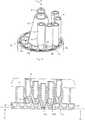
Wie in
Dabei ist der erste Gelenkkörper
Der Revolver
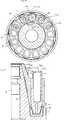
Wie der Darstellung nach
Wie in
Die Raststifte
Durch die Vorspannelemente sind die Raststifte
Der erste Gelenkkörper
Wie weiter oben erwähnt, ist die Zahl an Raststiften
Die Raststifte
Die Rastvertiefungen
Die Art und Weise, wie die Raststifte
Wie in
Die den vollständig eingetauchten Raststift
Wie in
Wie insbesondere aus der Darstellung nach
Da der vollständig eingetauchte Raststift
Bezugszeichenliste LIST OF REFERENCE NUMBERS
- 1010
- Haltearmholding arm
- 12, 14, 16, 18, 20, 2212, 14, 16, 18, 20, 22
- Haltegliederretaining members
- 24, 26, 28, 30, 3224, 26, 28, 30, 32
- Gelenkejoints
- 3636
- Handgriffhandle
- 4040
- erster Gelenkkörperfirst joint body
- 4242
- zweiter Gelenkkörpersecond joint body
- 4444
- DurchgangsbohrungenThrough holes
- 4646
- Raststiftelocking pins
- 4848
- Rastvertiefungenlocking recesses
- 5050
- Rastscheibelocking disc
- 5252
- Hebeelementlifting member
- 5454
- Ringflanschannular flange
- 5656
- Aussparungrecess
- 5858
- Stufestep
- 6060
- Aufnahmebohrunglocation hole
- 6161
- Entlüftungsbohrungvent hole
- 6262
- Lagerkonusbearing cone
- 6464
- Befestigungsschraubefixing screw
- 6666
- Eingriffsteilengaging part
- 68, 7268, 72
- Anlageflächencontact surfaces
ZITATE ENTHALTEN IN DER BESCHREIBUNG QUOTES INCLUDE IN THE DESCRIPTION
Diese Liste der vom Anmelder aufgeführten Dokumente wurde automatisiert erzeugt und ist ausschließlich zur besseren Information des Lesers aufgenommen. Die Liste ist nicht Bestandteil der deutschen Patent- bzw. Gebrauchsmusteranmeldung. Das DPMA übernimmt keinerlei Haftung für etwaige Fehler oder Auslassungen.This list of the documents listed by the applicant has been generated automatically and is included solely for the better information of the reader. The list is not part of the German patent or utility model application. The DPMA assumes no liability for any errors or omissions.
Zitierte PatentliteraturCited patent literature
- DE 10209209 B4[0004, 0010]DE 10209209 B4[0004, 0010]
Claims (12)
Translated fromGermanPriority Applications (10)
| Application Number | Priority Date | Filing Date | Title |
|---|---|---|---|
| DE102012112716.6ADE102012112716A1 (en) | 2012-12-20 | 2012-12-20 | Medical support arm |
| EP13817893.4AEP2934360B1 (en) | 2012-12-20 | 2013-12-03 | Medical holding arm |
| RU2015110499/14ARU2599682C1 (en) | 2012-12-20 | 2013-12-03 | Medical retaining lever |
| BR112015010406ABR112015010406A2 (en) | 2012-12-20 | 2013-12-03 | medical support arm |
| US14/648,865US10072793B2 (en) | 2012-12-20 | 2013-12-03 | Medical holding arm |
| PL13817893TPL2934360T3 (en) | 2012-12-20 | 2013-12-03 | Medical holding arm |
| PCT/EP2013/075337WO2014095338A1 (en) | 2012-12-20 | 2013-12-03 | Medical holding arm |
| KR1020157014579AKR101705475B1 (en) | 2012-12-20 | 2013-12-03 | Medical holding arm |
| JP2015541195AJP6091637B2 (en) | 2012-12-20 | 2013-12-03 | Medical holding arm |
| CN201380056361.1ACN104755040B (en) | 2012-12-20 | 2013-12-03 | The retaining arm of medical treatment |
Applications Claiming Priority (1)
| Application Number | Priority Date | Filing Date | Title |
|---|---|---|---|
| DE102012112716.6ADE102012112716A1 (en) | 2012-12-20 | 2012-12-20 | Medical support arm |
Publications (1)
| Publication Number | Publication Date |
|---|---|
| DE102012112716A1true DE102012112716A1 (en) | 2014-06-26 |
Family
ID=49918666
Family Applications (1)
| Application Number | Title | Priority Date | Filing Date |
|---|---|---|---|
| DE102012112716.6AWithdrawnDE102012112716A1 (en) | 2012-12-20 | 2012-12-20 | Medical support arm |
Country Status (10)
| Country | Link |
|---|---|
| US (1) | US10072793B2 (en) |
| EP (1) | EP2934360B1 (en) |
| JP (1) | JP6091637B2 (en) |
| KR (1) | KR101705475B1 (en) |
| CN (1) | CN104755040B (en) |
| BR (1) | BR112015010406A2 (en) |
| DE (1) | DE102012112716A1 (en) |
| PL (1) | PL2934360T3 (en) |
| RU (1) | RU2599682C1 (en) |
| WO (1) | WO2014095338A1 (en) |
Cited By (2)
| Publication number | Priority date | Publication date | Assignee | Title |
|---|---|---|---|---|
| DE102014113658A1 (en) | 2014-09-22 | 2016-03-24 | MAQUET GmbH | Device for repositioning bone fracture fragments |
| DE102017110719A1 (en)* | 2017-05-17 | 2018-11-22 | MAQUET GmbH | Surgical rotation unit with improved rotation locking |
Families Citing this family (6)
| Publication number | Priority date | Publication date | Assignee | Title |
|---|---|---|---|---|
| DE102012100970B4 (en) | 2012-02-07 | 2014-01-09 | MAQUET GmbH | Device for manually unlocking a load mechanism to be loaded |
| EP3285652B1 (en)* | 2015-04-21 | 2018-12-05 | Koninklijke Philips N.V. | An adjustable arm for a patient monitoring device |
| CN107701909B (en)* | 2017-10-31 | 2023-05-19 | 北京建筑大学 | Combination of splicable structural units and splicable structural units |
| CN108673556B (en)* | 2018-07-18 | 2024-06-04 | 深圳熙康医疗科技有限公司 | Mechanical arm |
| US11517396B2 (en) | 2019-02-27 | 2022-12-06 | Zimmer Biomet CMF and Thoracic, LLC | Retractable gear meshing joint and arm |
| KR102251806B1 (en)* | 2020-10-30 | 2021-05-13 | 정규성 | Articulated Support Device |
Citations (1)
| Publication number | Priority date | Publication date | Assignee | Title |
|---|---|---|---|---|
| DE10209209B4 (en) | 2002-03-04 | 2006-03-30 | Helmut C. Hartwig | Stepless lock, in particular swivel joint with such |
Family Cites Families (30)
| Publication number | Priority date | Publication date | Assignee | Title |
|---|---|---|---|---|
| US3419295A (en)* | 1966-03-18 | 1968-12-31 | Cohen Alfred G | Hinge coupling unit for tiltable umbrella |
| US3379034A (en)* | 1966-10-14 | 1968-04-23 | Crompton & Knowles Corp | Yieldable drive couplings |
| US3803667A (en) | 1972-02-07 | 1974-04-16 | A Rose | Universal handle for surgical implements |
| SU1088723A1 (en)* | 1983-02-16 | 1984-04-30 | Военно-медицинская академия им.С.М.Кирова | Apparatus for orthopedic operations |
| GB2155790B (en)* | 1984-03-16 | 1987-02-25 | Steeper Hugh Ltd | Elbow lock mechanism |
| IT1188533B (en)* | 1986-01-31 | 1988-01-14 | Fimtessile | CONTROL MECHANISM OF SWIVEL CONNECTIONS SWITCHES OF LICCI PAINTINGS IN A ROTARY DOBBY |
| US4971037A (en) | 1988-09-19 | 1990-11-20 | Pilling Co. | Surgical retractor support |
| RU1774087C (en)* | 1990-07-09 | 1992-11-07 | Всесоюзный Научно-Исследовательский Институт Медицинского Приборостроения | Pivot connection |
| WO1997030653A1 (en) | 1996-02-26 | 1997-08-28 | Biopsys Medical, Inc. | Articulating guide arm for medical applications |
| US5727899A (en) | 1996-09-13 | 1998-03-17 | Minnesota Scientific, Inc. | Fulcrum clamp |
| US6283912B1 (en) | 1999-05-04 | 2001-09-04 | Cardiothoracic Systems, Inc. | Surgical retractor platform blade apparatus |
| US7594912B2 (en) | 2004-09-30 | 2009-09-29 | Intuitive Surgical, Inc. | Offset remote center manipulator for robotic surgery |
| US6616664B2 (en) | 1999-10-21 | 2003-09-09 | Ebi L.P. | Clamp assembly for an external fixation system |
| JP3519328B2 (en) | 1999-11-15 | 2004-04-12 | ゾンネ医科工業株式会社 | Medical device holding device |
| US6562045B2 (en) | 2001-02-13 | 2003-05-13 | Sdgi Holdings, Inc. | Machining apparatus |
| ATE484228T1 (en) | 2001-05-23 | 2010-10-15 | Boss Instr Ltd | RETRACTOR CLAMP COMPOSITION |
| US20040143153A1 (en) | 2003-01-17 | 2004-07-22 | Sharrow James S. | Devices and methods for manipulation of organ tissue |
| US6767153B1 (en) | 2003-02-10 | 2004-07-27 | Dana W. Holbrook | Locking positional arm device |
| DE102004043982B4 (en) | 2004-09-11 | 2010-04-01 | Karl Storz Gmbh & Co.Kg | Holding device for cylindrical instrument body medical instruments |
| JP2006187815A (en)* | 2004-12-28 | 2006-07-20 | Yaskawa Electric Corp | Manipulator and transfer robot using the same |
| US20060234798A1 (en)* | 2005-04-14 | 2006-10-19 | Mighty Seven International Co., Ltd. | Clutch for power tool |
| DE602006003060D1 (en)* | 2006-02-28 | 2008-11-20 | First Spa | Improved compound coupling cone clutch in a rotary shaft machine for looms |
| US8216211B2 (en) | 2006-10-09 | 2012-07-10 | Brianlab Ag | Holding device for medical instruments |
| DE102007035922A1 (en) | 2007-07-23 | 2009-05-20 | Hans Dietle | connecting device |
| US20090036890A1 (en) | 2007-07-31 | 2009-02-05 | John Peter Karidis | Fixator apparatus with radiotransparent apertures for orthopaedic applications |
| JP5090940B2 (en) | 2008-01-28 | 2012-12-05 | 株式会社旭製作所 | One-touch coupler |
| DE102009009575A1 (en) | 2009-02-19 | 2010-08-26 | Hebumedical Gmbh | Holding arm for retractor system utilized during brain surgery, has holding mechanism for spatula, where arm is formed from bar made of nitinol, which is bendable by hand and is fastenable at linkage by attachment mechanism |
| DE102010016332A1 (en) | 2009-04-06 | 2011-03-24 | Gray, Bruce, Bentley | Surgical device |
| CN102462533B (en) | 2010-11-11 | 2014-03-12 | 北京理工大学 | Mechanical arm for clamping propelling mechanism of minimally invasive blood vessel interventional surgery |
| JP3166092U (en) | 2010-12-08 | 2011-02-17 | 株式会社メトラン | Arm device |
- 2012
- 2012-12-20DEDE102012112716.6Apatent/DE102012112716A1/ennot_activeWithdrawn
- 2013
- 2013-12-03KRKR1020157014579Apatent/KR101705475B1/ennot_activeExpired - Fee Related
- 2013-12-03USUS14/648,865patent/US10072793B2/enactiveActive
- 2013-12-03PLPL13817893Tpatent/PL2934360T3/enunknown
- 2013-12-03CNCN201380056361.1Apatent/CN104755040B/enactiveActive
- 2013-12-03JPJP2015541195Apatent/JP6091637B2/enactiveActive
- 2013-12-03RURU2015110499/14Apatent/RU2599682C1/ennot_activeIP Right Cessation
- 2013-12-03EPEP13817893.4Apatent/EP2934360B1/enactiveActive
- 2013-12-03WOPCT/EP2013/075337patent/WO2014095338A1/enactiveApplication Filing
- 2013-12-03BRBR112015010406Apatent/BR112015010406A2/ennot_activeApplication Discontinuation
Patent Citations (1)
| Publication number | Priority date | Publication date | Assignee | Title |
|---|---|---|---|---|
| DE10209209B4 (en) | 2002-03-04 | 2006-03-30 | Helmut C. Hartwig | Stepless lock, in particular swivel joint with such |
Cited By (5)
| Publication number | Priority date | Publication date | Assignee | Title |
|---|---|---|---|---|
| DE102014113658A1 (en) | 2014-09-22 | 2016-03-24 | MAQUET GmbH | Device for repositioning bone fracture fragments |
| US10478362B2 (en) | 2014-09-22 | 2019-11-19 | MAQUET GmbH | Device for repositioning bone fracture fragments |
| DE102017110719A1 (en)* | 2017-05-17 | 2018-11-22 | MAQUET GmbH | Surgical rotation unit with improved rotation locking |
| WO2018211017A1 (en) | 2017-05-17 | 2018-11-22 | MAQUET GmbH | Surgical rotational unit with improved rotational locking |
| US11918520B2 (en) | 2017-05-17 | 2024-03-05 | MAQUET GmbH | Surgical rotational unit with improved rotational locking |
Also Published As
| Publication number | Publication date |
|---|---|
| CN104755040A (en) | 2015-07-01 |
| BR112015010406A2 (en) | 2017-07-11 |
| EP2934360B1 (en) | 2016-11-16 |
| KR20150083101A (en) | 2015-07-16 |
| CN104755040B (en) | 2017-06-16 |
| US20150297305A1 (en) | 2015-10-22 |
| EP2934360A1 (en) | 2015-10-28 |
| WO2014095338A1 (en) | 2014-06-26 |
| RU2599682C1 (en) | 2016-10-10 |
| JP2015536193A (en) | 2015-12-21 |
| JP6091637B2 (en) | 2017-03-08 |
| US10072793B2 (en) | 2018-09-11 |
| KR101705475B1 (en) | 2017-02-09 |
| PL2934360T3 (en) | 2017-06-30 |
Similar Documents
| Publication | Publication Date | Title |
|---|---|---|
| EP2934360B1 (en) | Medical holding arm | |
| DE29701099U1 (en) | Pin-shaped holding element for an orthopedic holding system | |
| DE102005012896B4 (en) | Vehicle seat with headrest | |
| DE202010000010U1 (en) | Adjustable lever | |
| EP4110136B1 (en) | Device for the translatory and rotary movement of an item relative to a carrier panel | |
| DE102009008188A1 (en) | Fastening device for a module element in an aircraft | |
| WO2015124745A1 (en) | Lifting column for a medical device | |
| EP2966243A1 (en) | Actuation handle | |
| DE202011002608U1 (en) | tripod head | |
| DE102011001251A1 (en) | implant | |
| DE20207486U1 (en) | Screwdriver ratchet structure | |
| DE102006056004B4 (en) | Articulated fitting for motor vehicle seats with at least two locking arms | |
| DE102011113392B4 (en) | Device for actuating a component, in particular a space component | |
| DE102017130340A1 (en) | Actuation handle with locking device | |
| DE202013103058U1 (en) | jig | |
| DE202023105047U1 (en) | A device for connecting a solar panel | |
| DE102012104101B4 (en) | Radial adjustment with locking function | |
| DE102019130253A1 (en) | Plain bearing, equipment device with at least one slide bearing and equipment device with at least one rotatable accommodated bearing | |
| DE102014213134B4 (en) | Disc arrangement with adjustable axial thickness and switching arrangement with the disc assembly | |
| DE3410158A1 (en) | Swivel joint with an axis | |
| DE2203765C3 (en) | adjusting spring | |
| DE202022002717U1 (en) | Clamping block, connecting bolt for two clamping blocks and arrangement of two clamping blocks and one connecting bolt | |
| DE202025102343U1 (en) | Reset device for a door handle set and door handle set with such a reset device | |
| DE1172915B (en) | Device for generating a rotary movement between two parts approaching in the axial direction | |
| DE2745191A1 (en) | LOCK WITH A LOCKING DEVICE |
Legal Events
| Date | Code | Title | Description |
|---|---|---|---|
| R082 | Change of representative | Representative=s name:SCHAUMBURG & PARTNER PATENTANWAELTE GBR, DE Representative=s name:ZACCO DR. PETERS UND PARTNER, DE Representative=s name:ZACCO PATENTANWALTS- UND RECHTSANWALTSGESELLSC, DE | |
| R082 | Change of representative | Representative=s name:ZACCO DR. PETERS UND PARTNER, DE Representative=s name:ZACCO PATENTANWALTS- UND RECHTSANWALTSGESELLSC, DE | |
| R079 | Amendment of ipc main class | Free format text:PREVIOUS MAIN CLASS: A61B0019000000 Ipc:A61B0090500000 | |
| R005 | Application deemed withdrawn due to failure to request examination |