DE102012108030B4 - Multiplexer with reduced intermodulation products - Google Patents
Multiplexer with reduced intermodulation productsDownload PDFInfo
- Publication number
- DE102012108030B4 DE102012108030B4DE102012108030.5ADE102012108030ADE102012108030B4DE 102012108030 B4DE102012108030 B4DE 102012108030B4DE 102012108030 ADE102012108030 ADE 102012108030ADE 102012108030 B4DE102012108030 B4DE 102012108030B4
- Authority
- DE
- Germany
- Prior art keywords
- multiplexer
- filter
- mul
- blocker
- path
- Prior art date
- Legal status (The legal status is an assumption and is not a legal conclusion. Google has not performed a legal analysis and makes no representation as to the accuracy of the status listed.)
- Expired - Fee Related
Links
- 230000000903blocking effectEffects0.000claimsabstractdescription84
- 230000005540biological transmissionEffects0.000claimsabstractdescription55
- 230000001939inductive effectEffects0.000claimsdescription39
- 238000010295mobile communicationMethods0.000claimsdescription13
- 238000010897surface acoustic wave methodMethods0.000claimsdescription11
- 238000004891communicationMethods0.000claimsdescription6
- 230000002452interceptive effectEffects0.000claimsdescription6
- 238000001465metallisationMethods0.000claimsdescription6
- 230000000704physical effectEffects0.000claimsdescription5
- 230000002457bidirectional effectEffects0.000claimsdescription4
- 239000004020conductorSubstances0.000claimsdescription4
- 239000000758substrateSubstances0.000claimsdescription3
- 230000003071parasitic effectEffects0.000claimsdescription2
- 238000011144upstream manufacturingMethods0.000claimsdescription2
- 230000008030eliminationEffects0.000claims2
- 238000003379elimination reactionMethods0.000claims2
- 230000037361pathwayEffects0.000claims1
- 238000000926separation methodMethods0.000claims1
- 230000000694effectsEffects0.000description13
- 238000004519manufacturing processMethods0.000description8
- 239000000463materialSubstances0.000description5
- XLOMVQKBTHCTTD-UHFFFAOYSA-NZinc monoxideChemical compound[Zn]=OXLOMVQKBTHCTTD-UHFFFAOYSA-N0.000description4
- 230000008859changeEffects0.000description3
- 230000003068static effectEffects0.000description3
- 102100026396ADP/ATP translocase 2Human genes0.000description2
- 101000718417Homo sapiens ADP/ATP translocase 2Proteins0.000description2
- PMHQVHHXPFUNSP-UHFFFAOYSA-Mcopper(1+);methylsulfanylmethane;bromideChemical compoundBr[Cu].CSCPMHQVHHXPFUNSP-UHFFFAOYSA-M0.000description2
- 230000008878couplingEffects0.000description2
- 238000010168coupling processMethods0.000description2
- 238000005859coupling reactionMethods0.000description2
- 238000009795derivationMethods0.000description2
- 238000010586diagramMethods0.000description2
- 238000005516engineering processMethods0.000description2
- 238000001914filtrationMethods0.000description2
- 238000002955isolationMethods0.000description2
- 230000009021linear effectEffects0.000description2
- 238000000034methodMethods0.000description2
- 230000009022nonlinear effectEffects0.000description2
- 230000001902propagating effectEffects0.000description2
- 239000011787zinc oxideSubstances0.000description2
- WSMQKESQZFQMFW-UHFFFAOYSA-N5-methyl-pyrazole-3-carboxylic acidChemical compoundCC1=CC(C(O)=O)=NN1WSMQKESQZFQMFW-UHFFFAOYSA-N0.000description1
- 229910013641LiNbO 3Inorganic materials0.000description1
- 239000013078crystalSubstances0.000description1
- 230000001419dependent effectEffects0.000description1
- 230000009977dual effectEffects0.000description1
- 239000007772electrode materialSubstances0.000description1
- 230000001976improved effectEffects0.000description1
- 230000003993interactionEffects0.000description1
- GQYHUHYESMUTHG-UHFFFAOYSA-Nlithium niobateChemical compound[Li+].[O-][Nb](=O)=OGQYHUHYESMUTHG-UHFFFAOYSA-N0.000description1
- 230000035699permeabilityEffects0.000description1
- 230000008092positive effectEffects0.000description1
- 230000009467reductionEffects0.000description1
- 238000004513sizingMethods0.000description1
- 238000002834transmittanceMethods0.000description1
- 238000004804windingMethods0.000description1
Images


Classifications
- H—ELECTRICITY
- H03—ELECTRONIC CIRCUITRY
- H03H—IMPEDANCE NETWORKS, e.g. RESONANT CIRCUITS; RESONATORS
- H03H9/00—Networks comprising electromechanical or electro-acoustic elements; Electromechanical resonators
- H03H9/70—Multiple-port networks for connecting several sources or loads, working on different frequencies or frequency bands, to a common load or source
- H03H9/703—Networks using bulk acoustic wave devices
- H03H9/706—Duplexers
- H—ELECTRICITY
- H03—ELECTRONIC CIRCUITRY
- H03H—IMPEDANCE NETWORKS, e.g. RESONANT CIRCUITS; RESONATORS
- H03H9/00—Networks comprising electromechanical or electro-acoustic elements; Electromechanical resonators
- H03H9/70—Multiple-port networks for connecting several sources or loads, working on different frequencies or frequency bands, to a common load or source
- H03H9/72—Networks using surface acoustic waves
- H03H9/725—Duplexers
- H—ELECTRICITY
- H04—ELECTRIC COMMUNICATION TECHNIQUE
- H04B—TRANSMISSION
- H04B15/00—Suppression or limitation of noise or interference
- H—ELECTRICITY
- H04—ELECTRIC COMMUNICATION TECHNIQUE
- H04L—TRANSMISSION OF DIGITAL INFORMATION, e.g. TELEGRAPHIC COMMUNICATION
- H04L5/00—Arrangements affording multiple use of the transmission path
- H04L5/14—Two-way operation using the same type of signal, i.e. duplex
Landscapes
- Engineering & Computer Science (AREA)
- Signal Processing (AREA)
- Physics & Mathematics (AREA)
- Acoustics & Sound (AREA)
- Computer Networks & Wireless Communication (AREA)
- Surface Acoustic Wave Elements And Circuit Networks Thereof (AREA)
- Piezo-Electric Or Mechanical Vibrators, Or Delay Or Filter Circuits (AREA)
Abstract
Translated fromGermanDescription
Translated fromGermanDie Erfindung betrifft Multiplexer mit verringerten Intermodulationsprodukten, insbesondere Multiplexer, bei denen Frequenzkomponenten, welche zu ungewünschten Intermodulationseffekten führen können, unterdrückt bzw. eliminiert werden.The invention relates to multiplexers with reduced intermodulation products, in particular multiplexers, in which frequency components which can lead to undesired intermodulation effects are suppressed or eliminated.
Intermodulationsprodukte oder Intermodulationsverzerrungen (englisch: IMD = intermodulation distortion) treten in nicht linearen Systemen und damit in realen technischen Systemen auf, wenn zwei oder mehrere Signale unterschiedlicher Frequenz verarbeitet werden. So kann es passieren, dass beim Mischen an einem nicht linearen Schaltungselement Produkte der beiden Signale erzeugt werden. Im Fall zweier Signale der Form

In Multiplexern und speziell in Duplexern sind diejenigen Intermodulationsprodukte problematisch, welche an einem Antenneneingang entstehen und im Rx-Band oder in der Nähe des Rx-Bandes liegen. Diese „blockieren“ den Rx-Signalpfad, da sie nicht einfach durch Filterungsmaßnahmen herausgefiltert werden können. Sonst würde auch die Rx-Nutzfrequenz zerstört. Solche unerwünschten Intermodulationsprodukte können insbesondere in Duplexern durch die Multiplikation von Tx-Signalen mit einem von extern über die Antenne empfangenen Blockersignal entstehen. Das zu einem Tx-Signal zugehörige Rx-Passband liegt im Falle eines Duplexers relativ nahe, meist oberhalb des Tx-Passbandes. Somit fallen zwar nicht Harmonische des Tx-Signals, wohl aber Intermodulationsprodukte aus dem Tx-Signal und einem von extern empfangenen Signal in das eigene Rx-Passband.In multiplexers, and especially in duplexers, those intermodulation products which are created at an antenna input and located in the Rx band or in the vicinity of the Rx band are problematic. These "block" the Rx signal path, as they can not be easily filtered out by filtering. Otherwise, the Rx useful frequency would be destroyed. Such unwanted intermodulation products can arise, in particular in duplexers, by the multiplication of Tx signals with a blocking signal received externally via the antenna. The Rx passband associated with a Tx signal is relatively close in the case of a duplexer, usually above the Tx passband. Thus, although not harmonics of the Tx signal, but well fall intermodulation products from the Tx signal and an externally received signal in the own Rx pass band.
Im Vergleich zu Harmonischen, welche durch Hochpassfilter oder lokale Polstellen im Stoppband eines Sendefilters beseitigt werden können, muss deshalb ein anderer Weg als das Herausfiltern gewählt werden.Compared to harmonics which can be eliminated by high pass filters or local poles in the stop band of a transmit filter, therefore, a different path than the filtering out has to be chosen.
Aus der
Aus der
Aus der
Nachteilig daran ist, dass für die zusätzlichen Resonatoren Platz auf der Oberfläche eines teuren Chips vorgesehen werden muss.The disadvantage of this is that space must be provided on the surface of an expensive chip for the additional resonators.
Es ist deshalb eine Aufgabe der vorliegenden Erfindung, einen Multiplexer mit verringerten Intermodulationseffekten anzugeben, der derzeitigen Miniaturisierungsanforderungen genügt, die Leistungsverträglichkeit nicht einschränkt, bei dem die Steigung der Filterflanken nicht vermindert ist und der für die Massenfertigung geeignet ist. Insbesondere ist es eine Aufgabe der vorliegenden Erfindung, einen Multiplexer anzugeben, bei dem Blockerfrequenzen bereits am Antennenknoten selbst oder im antennennahen Schaltungsbereich eliminiert werden. Ferner soll der Multiplexer kostengünstig herzustellen sein und Maßnahmen zur Verringerung von Intermodulationseffekten aufweisen, die sich leicht mit Maßnahmen zur Verringerung von Intermodulationseffekten aufgrund anderer Blockerfrequenzen kombinieren lassen. Weiterhin ist es eine Aufgabe, einen verbesserten Multiplexer anzugeben, bei dem keine zusätzlichen Fertigungsschritte bei der Herstellung erforderlich sind und bei dem nicht unbedingt zusätzliche externe Schaltungselemente erforderlich sind. Ferner soll der Multiplexer mit anderen Maßnahmen zur Verringerung von Intermodulationseffekten kompatibel sein. Ferner sollen die elektrischen Eigenschaften des Multiplexers nicht durch die Maßnahmen zur Verringerung der Intermodulationseffekten verschlechtert werden.It is therefore an object of the present invention to provide a multiplexer with reduced intermodulation effects, which meets current miniaturization requirements, does not limit the power compatibility, in which the slope of the filter edges is not reduced and which is suitable for mass production. In particular, it is an object of the present invention to specify a multiplexer in which blocking frequencies are already eliminated at the antenna node itself or in the antenna-near circuit area. Furthermore, the multiplexer should be inexpensive to manufacture and have measures to reduce intermodulation effects that can be easily combined with measures to reduce intermodulation effects due to other blocking frequencies. It is a further object to provide an improved multiplexer which does not require additional manufacturing fabrication steps and which does not necessarily require additional external circuit elements. Further the multiplexer should be compatible with other measures to reduce intermodulation effects. Furthermore, the electrical properties of the multiplexer should not be degraded by the measures to reduce the intermodulation effects.
Diese Aufgaben werden durch einen Multiplexer nach Anspruch 1 gelöst. Abhängige Ansprüche bilden die Erfindung in vorteilhafter Weise weiter.These objects are achieved by a multiplexer according to
Die Erfindung umfasst einen mit akustischen Wellen arbeitenden Multiplexer mit einem Sendeanschluss, einem Empfangsanschluss und einem gemeinsamen Anschluss. Der Multiplexer umfasst ferner einen Sendepfad, der zwischen dem Sendeanschluss und dem gemeinsamen Anschluss verschaltet ist und ein Sendefilter umfasst, sowie einen Empfangspfad, der zwischen dem Empfangsanschluss und dem gemeinsamen Anschluss geschaltet ist und ein Empfangsfilter umfasst. Ferner beinhaltet der Multiplexer einen Chip sowie einen mit dem gemeinsamen Anschluss verschalteten Blockerpfad. Der Blockerpfad umfasst dabei auf dem Chip angeordnete Blockerelektroden, die dazu vorgesehen sind, Blockersignale gegen Masse abzuleiten. Dabei sind Blockersignale solche Signale, die mit anderen im Multiplexer propagierenden Signalen multipliziert Intermodulationsprodukte ergeben, welche insbesondere in einem Rx-Frequenzbereich liegen können und somit den Rx-Pfad blockieren. Entsprechend sind Blockerelektroden solche Elektroden, die entsprechend ausgestaltet sind, um die Blockersignale gegen Masse abzuleiten.The invention includes an acoustic wave multiplexer having a transmit port, a receive port, and a common port. The multiplexer further comprises a transmission path connected between the transmission port and the common port and comprising a transmission filter and a reception path connected between the reception port and the common port and comprising a reception filter. Furthermore, the multiplexer includes a chip and a blocker path connected to the common terminal. The blocker path in this case comprises blocking electrodes arranged on the chip, which are provided to derive blocking signals to ground. In this case, blocker signals are those signals which multiply multiply with other propagating in the multiplexer signals intermodulation products, which may in particular lie in an Rx frequency range and thus block the Rx path. Correspondingly, blocker electrodes are those electrodes that are designed to divert the blocker signals to ground.
Es wird also ein Multiplexer angegeben, in dem Blockersignale über geeignete Maßnahmen entsprechend abgeleitet werden, sodass ein Mischen mit regulär in Multiplexern auftretenden Signalen im Idealfall gar nicht erst geschieht und somit Intermodulationsprodukte auch nicht erzeugt werden.Thus, a multiplexer is specified in which blocker signals are correspondingly derived by means of suitable measures, so that mixing with signals that occur regularly in multiplexers ideally does not even happen in the first place and thus intermodulation products are not generated either.
Der Multiplexer arbeitet mit akustischen Wellen. In Frage kommen beispielsweise akustische Oberflächenwellen (engl.: SAWs = Surface Acoustic Waves), akustische Volumenwellen (BAWs = Bulk Acoustic Waves) oder geführte akustische Volumenwellen (GBAWs = Guided Bulk Acoustic Waves). In jedem dieser Fälle dienen Elektrodenstrukturen in Verbindung mit einem piezoelektrischen Material dazu, aufgrund des piezoelektrischen Effekts zwischen akustischen Schwingungen und elektrischen Hochfrequenzsignalen zu wandeln. Mit akustischen Wellen arbeitende Multiplexer weisen also Elektroden auf, welche in Form von strukturierten Elektrodenfingern auf einem piezoelektrischen Substrat (im Falle von akustischen Oberflächenwellen oder geführten akustischen Oberflächenwellen) angeordnet sind oder welche sandwich-artig eine piezoelektrische Schicht einschließen und großflächig ausgebildet sind. Im Fall akustischer Oberflächenwellen oder geführter akustischer Oberflächenwellen umfasst der Chip dabei das piezoelektrische Material. Im Falle akustischer Volumenwellen ist die Sandwichstruktur aus Elektroden und piezoelektrischem Material, eventuell zusammen mit Spiegelschichten, auf einem Trägerchip angeordnet. Das Vorsehen von Blockerelektroden, um Blockersignale gegen Masse abzuleiten, ist deshalb kompatibel mit konventionellen Herstellungsprozessen für mit akustischen Wellen arbeitende Multiplexer.The multiplexer works with acoustic waves. For example, surface acoustic waves (SAWs), bulk acoustic waves (BAWs) or guided bulk acoustic waves (GBAWs) are possible. In each of these cases, electrode structures in conjunction with a piezoelectric material serve to convert between acoustic vibrations and high frequency electrical signals due to the piezoelectric effect. Multiplexers operating with acoustic waves therefore have electrodes which are arranged in the form of structured electrode fingers on a piezoelectric substrate (in the case of surface acoustic waves or guided surface acoustic waves) or which sandwich a piezoelectric layer and have a large area. In the case of surface acoustic waves or guided surface acoustic waves, the chip comprises the piezoelectric material. In the case of bulk acoustic waves, the sandwich structure of electrodes and piezoelectric material, possibly together with mirror layers, is arranged on a carrier chip. The provision of blocking electrodes for deriving blocker signals to ground is therefore compatible with conventional acoustical wave multiplexer manufacturing processes.
Deshalb lassen sich die Blockerelektroden leicht mit den Schaltungselementen der Multiplexer kombinieren und die Aufgabe der Erfindung wird in einfacher, aber wirkungsvoller Weise gelöst.Therefore, the blocker electrodes can be easily combined with the circuit elements of the multiplexers and the object of the invention is achieved in a simple but effective manner.
Der Begriff Multiplexer betrifft dabei eine Frequenzweiche mit mindestens einem gemeinsamen Anschluss, der ein Antennenanschluss sein kann, sowie einer Anzahl von m Tx-Signalpfaden und n Rx-Signalpfaden, wobei m und n natürliche Zahlen ≥ 1 sind. Insbesondere ist es möglich, dass der Multiplexer ein Duplexer mit einem Tx-Pfad und einem Rx-Pfad ist.The term multiplexer in this case relates to a crossover network with at least one common terminal, which may be an antenna terminal, as well as a number of m Tx signal paths and n Rx signal paths, where m and n are natural numbers ≥ 1. In particular, it is possible for the multiplexer to be a duplexer with a Tx path and an Rx path.
Die Blockerelektroden können Elektroden eines akustisch aktiven Filterelements sein. So kann ein aktives Blockerelement durch seine rein elektrische Wirkung, z. B. als kapazitives Element, Blockersignale in einem ersten Frequenzbereich und durch seine elektroakustische Wirkung Blockersignale in einem zweiten, vom ersten Frequenzbereich verschiedenen Frequenzbereich unterbinden oder vermindern. Es ist auch möglich, dass das Blockerelement so ausgelegt ist, dass seine rein elektrische Wirkung und seine elektroakustische Wirkung zusammenwirken und Blockersignale eines einzigen Frequenzbereichs noch besser unterdrücken.The blocking electrodes may be electrodes of an acoustically active filter element. Thus, an active blocking element by its purely electrical effect, eg. As a capacitive element, blocker signals in a first frequency range and prevent or reduce blocking signals in a second, different from the first frequency range frequency range by its electro-acoustic effect. It is also possible that the blocking element is designed so that its purely electrical effect and its electro-acoustic effect interact and even better suppress blockers of a single frequency range.
In einer Ausführungsform umfasst der Blockerpfad Schaltungselemente des Sendefilters oder des Empfangsfilters.In one embodiment, the blocker path includes circuit elements of the transmit filter or the receive filter.
Als Schaltungselemente des Sendefilters oder des Empfangsfilters, die gleichzeitig Blockerelektroden des Blockerpfads umfassen, kommen insbesondere Interdigitalstrukturen in Form von Interdigitalwandlern oder sandwich-artig gebaute BAW-Resonatoren in Frage. Dadurch, dass diese Strukturen entsprechend ausgestaltet sind, können sie gleichzeitig als Elemente des Sendepfads oder des Empfangspfads einerseits dienen und andererseits Schaltungselemente darstellen, über die Blockersignale gegen Masse abgeleitet werden können.Intermediate structures in the form of interdigital transducers or sandwich-type BAW resonators come into consideration in particular as circuit elements of the transmission filter or of the reception filter, which simultaneously comprise blocking electrodes of the blocker path. Because of these structures accordingly are configured, they can simultaneously serve as elements of the transmit path or the receive path on the one hand and on the other hand represent circuit elements, can be derived via the blocker signals to ground.
In einer Ausführungsform umfasst der Multiplexer einen oder mehrere mit akustischen Wellen arbeitende Resonatoren mit Blockerelektroden in einem oder mehreren Blockerpfaden, wobei jeder Blockerpfad oder jeder mit akustischen Wellen arbeitende Resonator mit Blockerelektroden dazu vorgesehen ist, zwei Blockerfrequenzen abzuleiten.In one embodiment, the multiplexer comprises one or more acoustic wave resonators having blocking electrodes in one or more blocking paths, each blocking path or each acoustic wave resonator having blocking electrodes being arranged to derive two blocking frequencies.
In einer Ausführungsform umfasst der Multiplexer einen oder mehrere weitere Sendepfade mit je einem weiteren Sendefilter und einen oder mehrere Empfangspfade mit je einem weiteren Empfangsfilter. So können neben einem Duplexer auch leicht Triplexer, Quadruplexer usw. erhalten werden.In one embodiment, the multiplexer comprises one or more further transmission paths, each with a further transmission filter and one or more reception paths, each with a further reception filter. Thus, in addition to a duplexer also easily triplexer, quadruplexer, etc. can be obtained.
In einer Ausführungsform arbeitet das Sendefilter und/oder das Empfangsfilter mit akustischen Oberflächenwellen, mit akustischen Volumenwellen oder mit geführten akustischen Volumenwellen.In one embodiment, the transmit filter and / or receive filter operates with surface acoustic waves, bulk acoustic waves, or guided bulk acoustic waves.
Es ist auch möglich, dass das Sendefilter mit einer der angegebenen Art akustischer Wellen arbeitet, während das Empfangsfilter mit einer anderen Art akustischer Wellen arbeitet. Dann ist es möglich, dass das Sendefilter bzw. die Elektrodenstrukturen des Sendefilters auf einem ersten Chip angeordnet sind und das Empfangsfilter bzw. die Empfangsfilterelektroden auf einem weiteren Chip angeordnet sind. Die Blockerelektroden können dabei auf dem ersten Chip und/oder auf dem weiteren Chip angeordnet sein. Es ist auch möglich, dass einige Schaltungselemente des Blockerpfads auf dem einen Chip angeordnet sind, während andere Schaltungselemente des Blockerpfads auf dem weiteren Chip angeordnet sind. Auch die Schaltungselemente des Blockerpfads können dabei mit unterschiedlichen Arten akustischer Wellen arbeiten.It is also possible that the transmission filter works with one of the specified type of acoustic waves, while the reception filter works with a different type of acoustic waves. Then it is possible that the transmission filter or the electrode structures of the transmission filter are arranged on a first chip and the reception filter and the reception filter electrodes are arranged on a further chip. The blocker electrodes can be arranged on the first chip and / or on the further chip. It is also possible that some circuit elements of the blocker path are arranged on the one chip, while other circuit elements of the blocker path are arranged on the further chip. The circuit elements of the blocker path can also work with different types of acoustic waves.
In einer Ausführungsform umfasst das Sendefilter BAW-Resonatoren und das Empfangsfilter SAW-Resonatoren. Die BAW-Resonatoren und die SAW-Resonatoren sind auf oder in verschiedenen Chips angeordnet. Somit wird ein Mehr-Die-Multiplexer erhalten, in dem die unterschiedlichen Filtertechnologien die unterschiedlichen Anforderungen an Sende- und Empfangsfilter, z. B. bezüglich der Leistungsfestigkeit, Selektion, Isolation, ..., sicherstellen.In one embodiment, the transmit filter comprises BAW resonators and the receive filter comprises SAW resonators. The BAW resonators and the SAW resonators are arranged on or in different chips. Thus, a multi-die multiplexer is obtained in which the different filter technologies meet the different requirements for transmit and receive filters, eg. As in terms of performance, selection, isolation, ..., ensure.
In einer Ausführungsform umfasst der Chip allerdings alle Schaltungselemente des Sendefilters und/oder des Empfangsfilters. Dann arbeitet der Multiplexer nur mit einer Art akustischer Wellen, wobei dann auch die Schaltungselemente des Blockerpfads auf dem Chip angeordnet sein können.In one embodiment, however, the chip comprises all the circuit elements of the transmit filter and / or the receive filter. Then the multiplexer works only with a kind of acoustic waves, in which case the circuit elements of the blocker path can then also be arranged on the chip.
In einer Ausführungsform umfasst der Blockerpfad einen elektroakustischen Resonator, der auf dem Chip angeordnet ist.In one embodiment, the blocker path includes an electroacoustic resonator disposed on the chip.
Der elektroakustische Resonator des Blockerpfads kann dabei ein Serien- oder Parallelzweigresonator des Sendefilters oder des Empfangsfilters sein. Der Blockerpfad kann zwei oder mehr elektroakustische Resonatoren umfassen. So kann der Blockerpfad zum Beispiel eine Serienschaltung aus einem Resonator im Serienzweig, gefolgt von einem weiteren Parallelzweig umfassen.The electroacoustic resonator of the blocker path may be a series or parallel branch resonator of the transmit filter or of the receive filter. The blocker path may include two or more electroacoustic resonators. For example, the blocker path may comprise a series connection of one resonator in the series branch, followed by another parallel branch.
Sende- oder Empfangsfilter können in Laddertype-Struktur verschaltete Serien- und Parallelzweigresonatoren umfassen, wobei die Laddertype-Struktur ingesamt ein Bandpassfilter darstellt. Auch kann nur ein Teil des jeweiligen Filters als Laddertype-Struktur ausgeführt sein, während übrige Filterelemete alternative Topologien, z. B. DMS (Dual Mode SAW) Strukturen, umfassenTransmit or receive filters may include ladder type structure interconnected series and parallel arm resonators, the ladder type structure being a total bandpass filter. Also, only a portion of the respective filter may be implemented as a ladder-type structure, while remaining filter elements have alternative topologies, e.g. As DMS (Dual Mode SAW) structures include
Die Verwendung eines Parallelzweigresonators, eines Sendefilters oder eines Empfangsfilters als Schaltungselement, welches Blockerelektroden des Blockerpfads umfasst, bietet sich dabei an, da Parallelzweigresonatoren, z. B. in Laddertype-Schaltungen, den Signalpfad mit Masse verschalten. So ist ein Massepfad gegeben, der den gemeinsamen Anschluss mit Masse verschaltet und über den Blockersignale gegen Masse abgeleitet werden können.The use of a parallel branch resonator, a transmit filter or a receive filter as a circuit element, which comprises blocker electrodes of the blocker path, offers itself here, since parallel branch resonators, z. B. in Laddertype circuits, connect the signal path to ground. So there is a ground path, which connects the common terminal to ground and can be derived via the blocker signals to ground.
In einer Ausführungsform umfasst der Blockerpfad ein induktives Element, das als Metallisierung im Sendefilter oder im Empfangsfilter auf dem Chip ausgeführt ist.In one embodiment, the blocker path comprises an inductive element, which is designed as a metallization in the transmission filter or in the reception filter on the chip.
Es ist auch möglich, dass das induktive Element als Metallisierung in einem Mehrlagensubstrat, auf dem der Chip angeordnet ist, ausgeführt ist. Ferner ist es möglich, dass das induktive Element als diskretes Element auf einem Modul, das den Chip enthält, oder als diskretes Element auf einer Leiterplatte, die mit dem Chip verschaltet ist, ausgeführt ist.It is also possible that the inductive element is designed as a metallization in a multi-layer substrate on which the chip is arranged. Furthermore, it is possible for the inductive element to be designed as a discrete element on a module containing the chip or as a discrete element on a printed circuit board which is connected to the chip.
Somit umfasst der Blockerpfad Blockerelektroden, die ein kapazitives Element darstellen und ein induktives Element. Das kapazitive und das induktive Element können in Serie oder parallel verschaltet sein und somit einen Schwingkreis darstellen. Die Resonanzfrequenz des Schwingkreises kann dabei so eingestellt werden, dass seine Resonanzfrequenz der Frequenz von Blockersignalen entspricht, die als besonders störend angesehen werden. Thus, the blocker path comprises blocker electrodes which constitute a capacitive element and an inductive element. The capacitive and the inductive element can be connected in series or in parallel and thus represent a resonant circuit. The resonant frequency of the resonant circuit can be adjusted so that its resonant frequency corresponds to the frequency of blocker signals, which are considered to be particularly disturbing.
Ganz allgemein kann dazu die Kapazität des kapazitiven Elements durch Einstellen der Fläche von BAW-Elektroden oder der Apertur und der Wandlerlänge oder der Fingeranzahl von Interdigitalstrukturen eingestellt werden. Ferner ist es im Wesentlichen auch möglich, den Abstand der Elektroden zum Einstellen der Kapazität geeignet vorzusehen.In general, the capacitance of the capacitive element can be adjusted by adjusting the area of BAW electrodes or the aperture and the transducer length or the number of fingers of interdigital structures. Furthermore, it is also substantially possible to appropriately provide the spacing of the electrodes for adjusting the capacitance.
Der Abstand der Elektrodenstrukturen bestimmt im Wesentlichen die Wellenlänge der akustischen Wellen, mit denen der Multiplexer arbeitet. Dabei ist es möglich, dass akustische aktive Elektrodenstrukturen als Blockerelektroden im Blockerpfad Verwendung finden. Es ist aber auch möglich, dass im relevanten Frequenzbereich akustisch inaktive Elektrodenstrukturen verwendet werden. Dann kann der Abstand und die Fläche der Blockerelektroden im Wesentlichen beliebig gewählt werden, um die Kapazität des kapazitiven Elements einzustellen.The spacing of the electrode structures essentially determines the wavelength of the acoustic waves with which the multiplexer operates. It is possible that acoustic active electrode structures are used as blocker electrodes in the blocker path. However, it is also possible that acoustically inactive electrode structures are used in the relevant frequency range. Then, the distance and the area of the blocker electrodes can be selected substantially arbitrarily to adjust the capacitance of the capacitive element.
Die Induktivität des induktiven Elements kann durch die Länge der Leiterabschnitte des induktiven Elements eingestellt werden. Ferner ist es möglich, Windungen vorzusehen, wobei die Windungszahl eingestellt werden kann, um die Induktivität des induktiven Elements einzustellen. Insgesamt sind also viele Möglichkeiten wählbar, um die Kapazität des kapazitiven Elements oder die Induktivität des induktiven Elements einzustellen, um eine gute Ableitung der Blockersignale gegen Masse zu erhalten.The inductance of the inductive element can be adjusted by the length of the conductor sections of the inductive element. Further, it is possible to provide windings, wherein the number of turns can be adjusted to adjust the inductance of the inductive element. Overall, therefore, many options are available to adjust the capacitance of the capacitive element or the inductance of the inductive element in order to obtain a good derivative of the blocking signals to ground.
In einer Ausführungsform weist das induktive Element eine geringe Induktivität auf. So kann das induktive Element lediglich durch eine Zuleitung gebildet sein, wobei die Induktivität des induktiven Elements dann die parasitäre Induktivität der Zuleitung ist. Ist eine geringe Induktivität gewünscht, so wird die Induktivität als intrinsische Induktivität einer ohnehin vorhandenen Zuleitung erhalten, wodurch Platz gespart wird und ein klein bauendes Multiplexer-Bauelement erhalten wird.In one embodiment, the inductive element has a low inductance. Thus, the inductive element may be formed only by a supply line, wherein the inductance of the inductive element is then the parasitic inductance of the supply line. If a low inductance is desired, the inductance is obtained as an intrinsic inductance of an already existing feed line, whereby space is saved and a small-sized multiplexer component is obtained.
In einer Ausführungsform weist das Sendefilter und/oder das Empfangsfilter BAW-Resonatoren auf. Der Blockerpfad weist einen BAW-Resonator auf, dessen Massebelegung von der Massebelegung der Resonatoren des Sendefilters und/oder der Massebelegung der Resonatoren des Empfangsfilters abweicht.In one embodiment, the transmit filter and / or the receive filter comprise BAW resonators. The blocker path has a BAW resonator whose mass assignment deviates from the ground occupation of the resonators of the transmit filter and / or the ground occupation of the resonators of the receive filter.
So wird ein kapazitives Element im Blockerpfad erhalten, bei dem die elektrischen und/oder akustischen Eigenschaften der Blockerelektroden zur Ableitung von Blockersignalen gegen Masse optimiert sind. Ferner wird so ein Mittel angegeben, um die akustischen Eigenschaften vorteilhaft einzustellen.Thus, a capacitive element in the blocker path is obtained in which the electrical and / or acoustic properties of the blocker electrodes are optimized for the derivation of blocker signals to ground. Further, such a means is given to adjust the acoustic properties advantageous.
In einer Ausführungsform weist der Blockerpfad einen BAW-Resonator auf, der mehr oder weniger Schichten als ein Resonator des Sendefilters oder des Empfangsfilters aufweist. Dadurch wird die Resonanzfrequenz stark verschoben und es wird ein vorteilhaftes kapazitives Verhalten im Frequenzbereich der Passbänder erhalten.In one embodiment, the blocker path comprises a BAW resonator having more or fewer layers than a resonator of the transmit filter or the receive filter. As a result, the resonant frequency is shifted strongly and an advantageous capacitive behavior in the frequency range of the passbands is obtained.
In einer Ausführungsform weist der Blockerpfad (BP) einen BAW Resonator (R) auf, bei dem eine oder mehrere Schichten relativ zu einem BAW Resonator des Sendefilters (Tx) oder Empfangsfilters (Rx) in der Dicke unterschiedlich ist/sind.In one embodiment, the blocker path (BP) comprises a BAW resonator (R) in which one or more layers are different in thickness relative to a BAW resonator of the transmit filter (Tx) or receive filter (Rx).
In einer Ausführungsform weist der Blockerpfad einen BAW-Resonator auf, wobei eine physikalische Eigenschaft einer Schicht im Vergleich zu den physikalischen Eigenschaften entsprechender Schichten von Resonatoren des Sendefilters und/oder Empfangsfilters verändert ist. Das Verändern physikalischer Eigenschaften, z. B. der Massenbelegung, der Dicke, der Anzahl der Schichten, der akustischen Impedanz oder der elektrischen Leitfähigkeit, stellt eine einfache Möglichkeit dar, einen BAW-Resonator zu erhalten, der nicht nur Teil des Sendefilters und/oder Empfangsfilters ist, sondern auch Teil des Blockerpfads ist und somit zusätzlichen Anforderungen genügen muss.In one embodiment, the blocker path comprises a BAW resonator wherein a physical property of a layer is altered compared to the physical properties of corresponding layers of resonators of the transmit filter and / or receive filter. Changing physical properties, e.g. B. the mass occupancy, the thickness, the number of layers, the acoustic impedance or the electrical conductivity is an easy way to obtain a BAW resonator, which is not only part of the transmit filter and / or receiving filter, but also part of Blocker paths and thus must meet additional requirements.
In einer Ausführungsform umfasst der Blockerpfad einen BAW-Resonator, dessen Arbeitsfrequenz durch Geometrieänderungen im Vergleich zu BAW-Resonatoren des Sendefilters und/oder Empfangsfilters verändert ist.In one embodiment, the blocker path comprises a BAW resonator whose operating frequency is changed by geometry changes in comparison to BAW resonators of the transmit filter and / or receive filter.
Zusätzlich zu den oben genannten Eigenschaften können auch Geometrieänderungen, z. B. eine geänderte Grundfläche des Resonators, dazu dienen, einen auf mehrere Anforderungen hin optimierten Resonator zu erhalten. In addition to the above properties also geometry changes, for. As a modified base of the resonator, serve to obtain a multi-requisite optimized resonator.
Eine geänderte Geometrie bei mit akustischen Oberflächenwellen arbeitenden Multiplexern ist beispielsweise durch eine geänderte Metallisierungshöhe, eine Änderung des Pitches, also eine Änderung des Abstands von Fingerelektrodenmitte zu Fingerelektrodenmitte, oder eine Veränderung des Metallisierungsverhältnisses η möglich.A changed geometry in surface acoustic wave multiplexers is possible, for example, by a changed metallization height, a change in the pitch, ie a change in the distance from the middle of the finger electrode to the middle of the finger electrode, or a change in the metallization ratio η.
Das Resonanzverhalten eines Resonators ist nicht beliebig schmalbandig. Daher wird eine positive Wirkung bereits erzielt, auch wenn die Resonanzfrequenz des Schwingkreises - z. B. des Blockerresonators alleine oder einer Serienschaltung aus Blockerresonator und induktivem Element - frequenzmäßig lediglich in der Nähe des Blockerbandes liegt.The resonance behavior of a resonator is not arbitrarily narrowband. Therefore, a positive effect is already achieved, even if the resonant frequency of the resonant circuit -. B. the blocker resonator alone or a series circuit of blocking resonator and inductive element - in terms of frequency only in the vicinity of the blocker belt.
Die Resonanzfrequenz eines Schwingkreises mit einer Kapazität C und eine Induktivität L liegt bei
In einer Ausführungsform umfasst der Blockerpfad ein kapazitives Element, das akustisch inaktiv ist. Ein solches akustisch inaktives Element kann ein kapazitives Element sein, welches lediglich in entsprechenden Frequenzbereichen, z. B. Tx-Frequenzbereich oder Rx-Frequenzbereich, inaktiv ist, oder welches gar nicht mit akustischen Wellen wechselwirkt. Dazu ist es z. B. möglich, ein nicht piezoelektrisches Material anstelle eines piezoelektrischen Materials zwischen BAW-Elektroden anzuordnen. Es ist auch möglich, leitendes Material aus Spiegelschichten eines BAW-Resonators, z. B. aus dem Elektrodenmaterial der eigentlichen BAW-Elektroden, als Elektroden für akustisch im Wesentlichen inaktive kapazitive Elemente zu verwenden. Zudem ist es möglich, eine der eigentlichen BAW-Elektroden und eine leitende Spiegelschicht mit einer Zwischenlage Oxid zu einem kapazitiven Element zu verschalten.In one embodiment, the blocker path includes a capacitive element that is acoustically inactive. Such an acoustically inactive element may be a capacitive element which only in corresponding frequency ranges, for. B. Tx frequency range or Rx frequency range, is inactive, or which does not interact with acoustic waves. This is z. Example, possible to arrange a non-piezoelectric material instead of a piezoelectric material between BAW electrodes. It is also possible, conductive material from mirror layers of a BAW resonator, z. B. from the electrode material of the actual BAW electrodes to use as electrodes for acoustically substantially inactive capacitive elements. In addition, it is possible to connect one of the actual BAW electrodes and a conductive mirror layer with an intermediate oxide to a capacitive element.
In einer Ausführungsform umfasst der Multiplexer also einen BAW-Resonator mit Blockerelektroden, wobei zumindest eine der BAW-Elektroden und/oder eine ein leitendes Material umfassende Spiegelschicht eine Blockerelektrode darstellt.In one embodiment, the multiplexer thus comprises a BAW resonator with blocking electrodes, wherein at least one of the BAW electrodes and / or a mirror layer comprising a conductive material constitutes a blocking electrode.
Ferner ist es möglich, bei mit akustischen Oberflächenwellen oder geführten akustischen Volumenwellen arbeitenden Elektrodenstrukturen die Ausrichtung der Fingerelektroden relativ zu möglichen Ausbreitungsrichtungen akustischer Wellen zu verdrehen, sodass der elektroakustische Kopplungskoeffizient k2 verschwindet. Solche kapazitiven Elemente wirken rein kapazitiv, sodass ihre physikalischen Dimensionen so gewählt werden können, dass keine negative elektroakustische Interaktion mit Tx- oder Rx-Signalen auftritt.Further, in electrode structures operating with surface acoustic waves or guided bulk acoustic waves, it is possible to twist the orientation of the finger electrodes relative to possible propagation directions of acoustic waves, so that the electroacoustic coupling coefficient k2 disappears. Such capacitive elements are purely capacitive, so that their physical dimensions can be chosen so that no negative electroacoustic interaction with Tx or Rx signals occurs.
In einer Ausführungsform umfasst der Multiplexer zwei oder mehr Blockerpfade mit auf dem Chip angeordneten Blockerelektroden, die dazu vorgesehen sind, Blockersignale gegen Masse abzuleiten.In one embodiment, the multiplexer includes two or more blocker paths with on-chip blocker electrodes arranged to drain blocking signals to ground.
Es ist auch möglich, verschiedene Teile eines oder mehrerer Blockerpfade auf verschiedene Chips zu verteilen, falls der Multiplexer mehrere Chips umfasst.It is also possible to distribute different parts of one or more blocker paths to different chips if the multiplexer comprises several chips.
So können mehrere Blockerpfade vorgesehen werden, wobei jeder Blockerpfad zum Ableiten gegen Masse eines jeweils anderen Blockersignals vorgesehen ist. So können eine Vielzahl von Blockerfrequenzen unschädlich gemacht werden, ohne dass Intermodulation mit Tx-Signalen auftritt.Thus, a plurality of blocker paths may be provided, each blocker path being provided for deriving ground from a respective other blocker signal. Thus, a variety of blocking frequencies can be made harmless without intermodulation with Tx signals occurs.
In einer Ausführungsform umfasst der Multiplexer ein Sendefilter und ein Empfangsfilter. Der Multiplexer umfasst ferner einen ersten Blockerpfad, der mit einem zwischen dem Sendefilter und dem gemeinsamen Anschluss angeordneten Knoten verschaltet ist, und einen zweiten Blockerpfad, der mit einem zwischen dem Empfangsfilter und dem gemeinsamen Anschluss angeordneten Knoten verschaltet ist.In one embodiment, the multiplexer comprises a transmit filter and a receive filter. The multiplexer further comprises a first blocker path interconnected with a node located between the transmit filter and the common port and a second blocker path interconnected with a node located between the receive filter and the common port.
Ferner ist es möglich, dass ein Filter zwei, drei, vier oder mehr Blockerpfade aufweist.Further, it is possible for a filter to have two, three, four or more blocker paths.
So können leicht Intermodulationen zwischen verschiedenen Blockerfrequenzen und einerseits Tx-Signalen aus dem Sendefilter und andererseits von Signalen, die vom Empfangsfilter an den gemeinsamen Anschluss oder an das Sendefilter reflektiert werden, eliminiert werden.Thus, it is easy to eliminate intermodulation between different blocking frequencies and, on the one hand, Tx signals from the transmit filter and, on the other hand, signals reflected from the receive filter to the common port or to the transmit filter.
In einer Ausführungsform umfasst der Multiplexer genau ein Sendefilter und genau ein Empfangsfilter und stellt dadurch einen Duplexer dar. In one embodiment, the multiplexer comprises exactly one transmit filter and exactly one receive filter and thereby represents a duplexer.
Wenn die Summe der Frequenzen des Tx-Signals und des Blockersignals im Wesentlichen der Frequenz der Rx-Signale entspricht, z. B. im WCDMA-Band 2 mit Tx-Frequenzen zwischen 1880 MHz und 1910 MHz und Rx-Frequenzen zwischen 1930 MHz und 1990 MHz bei Blockerfrequenzen um 20 MHz und 140 MHz, würden Intermodulationsprodukte zweiter Ordnung im Rx-Frequenzbereich liegen. In einer solchen Situation ist es besonders vorteilhaft, wenn Blockersignale auf diese einfache Art und Weise so eliminiert werden, dass Intermodulationsprodukte erst gar nicht entstehen.When the sum of the frequencies of the Tx signal and the blocker signal is substantially equal to the frequency of the Rx signals, e.g. B. in
Entsprechend vorteilhaft ist das Ableiten von Blockersignalen auch dann, wenn der Betrag der Differenz aus Tx-Signalen und Blockersignalen der Frequenz der Rx-Signale entspricht. Dies ist z. B. bei Blocksignalen der Frequenzen 3760 MHz und 3900 MHz der Fall.Accordingly, the derivation of blocking signals is also advantageous if the amount of the difference between Tx signals and blocker signals corresponds to the frequency of the Rx signals. This is z. B. in block signals of the frequencies 3760 MHz and 3900 MHz the case.
Weiter praktisch von Bedeutung ist die Situation, wenn der Betrag der Differenz aus zweifacher Tx-Frequenz und Blockerfrequenz der Rx-Frequenz entspricht. Dies ist beispielsweise bei Blockerfrequenzen um 1770 MHz und 1890 MHz und zwischen 5630 MHz und 5810 MHz der Fall.Also of practical significance is the situation when the magnitude of the difference of twice the Tx frequency and the blocking frequency corresponds to the Rx frequency. This is the case for example at blocking frequencies around 1770 MHz and 1890 MHz and between 5630 MHz and 5810 MHz.
In einer Ausführungsform werden Resonatoren des Sendefilters und/oder des Empfangsfilters gedoppelt ausgeführt, wobei die jeweils gedoppelten Resonatoren antiparallel geschaltet sind, um nicht lineare Effekte zu reduzieren.In one embodiment, resonators of the transmit filter and / or the receive filter are performed doubled, with the doubled resonators each being connected in anti-parallel to reduce non-linear effects.
Bei der seriellen Aufdoppelung wird dabei ein Resonator durch zwei hintereinander geschaltete Resonatoren der jeweils doppelten Fläche ersetzt, sodass die Gesamtimpedanz der gedoppelten Resonatoren der Impedanz des ersetzten Resonators entspricht. Bei paralleler Aufdoppelung wird ein Resonator durch zwei parallel geschaltete Resonatoren der halben Fläche ersetzt, um die gleiche Impedanz der ersetzten Resonatoren zu erhalten. Dazu ist es möglich, mit Hilfe von Durchkontaktierungen (Vias) oder Bumpverbindungen eine obere Elektrode eines Resonators und die untere Elektrode des entsprechenden anderen Resonators an einem Knotenpunkt zu verschalten.In the case of the serial doubling, a resonator is replaced by two resonators of twice the area connected in series, so that the total impedance of the doubled resonators corresponds to the impedance of the replaced resonator. With parallel doubling, a resonator is replaced by two half-surface resonators connected in parallel to obtain the same impedance of the replaced resonators. For this purpose, it is possible with the aid of vias or bump connections to connect an upper electrode of a resonator and the lower electrode of the corresponding other resonator at a node.
In einer Ausführungsform ist der gemeinsame Anschluss über ein induktives Element mit Masse verschaltet, so das ein ESD-Schutz erhalten wird. Dabei leitet das induktive Element durch den gemeinsamen Anschluss, z. B. eine Antenne, empfangene ESD-Signale direkt an Masse ab, sodass das Sendefilter und insbesondere das empfindliche Empfangsfilter von dem breitbandigen ESD-Signal geschützt ist.In one embodiment, the common connection is connected to ground via an inductive element, so that an ESD protection is obtained. In this case, the inductive element passes through the common connection, z. As an antenna, received ESD signals directly from ground, so that the transmission filter and in particular the sensitive receiving filter is protected by the broadband ESD signal.
Es ist auch möglich, dass der ESD-Schutzpfad neben dem induktiven Element ein zum induktiven Element in Reihe geschaltetes kapazitives Element aufweist.It is also possible for the ESD protection path to have, in addition to the inductive element, a capacitive element connected in series with the inductive element.
In einer Ausführungsform umfasst der Sendepfad zwischen dem Sendefilter und dem gemeinsamen Anschluss ein Impedanz-Anpassnetzwerk. Es ist auch möglich, dass ein Impedanz-Anpassnetzwerk zwischen dem gemeinsamen Anschluss und dem Empfangsfilter angeordnet ist.In one embodiment, the transmit path between the transmit filter and the common port includes an impedance matching network. It is also possible that an impedance matching network is arranged between the common terminal and the reception filter.
In einer Ausführungsform umfasst das Sendefilter des Multiplexers oder das Empfangsfilter des Multiplexers ein Bandpassfilter oder ein Bandsperrfilter. Bandpassfilter und Bandsperrfilter können beide in SAW- oder BAW-Technologie gefertigt werden und somit die entsprechenden Resonatoren auf dem Chip angeordnet werden.In one embodiment, the transmit filter of the multiplexer or the receive filter of the multiplexer comprises a bandpass filter or a band rejection filter. Bandpass filters and bandstop filters can both be fabricated in SAW or BAW technology and thus the corresponding resonators can be arranged on the chip.
In einer Ausführungsform umfasst der Multiplexer einen oder mehrere Sperrkreise für Blockerfrequenzen, wobei der eine oder die mehreren Sperrkreise zwischen einer Antenne und dem gemeinsamen Anschluss CC angeordnet sind.In an embodiment, the multiplexer comprises one or more blocking frequency blocking circuits, the one or more blocking circuits being disposed between an antenna and the common terminal CC.
In einer Ausführungsform umfasst der Multiplexer einen Sperrkreis zwischen dem gemeinsamen Anschluss CC und einem Filter im Empfangs- oder Sendepfad.In one embodiment, the multiplexer comprises a blocking circuit between the common terminal CC and a filter in the receive or transmit path.
In einem Sperrkreis kann ein akustisch aktives Element verschaltet sein.In a blocking circuit, an acoustically active element can be interconnected.
In einer Ausführungsform umfasst der Multiplexer einen Sendepfad mit einem Bandsperrfilter, das undurchlässig für Blockerfrequenzen bezüglich eines Empfangspfades ist. Es ist möglich, dass das Sendefilter des Sendepfads ausschließlich aus dem Bandsperrfilter besteht. Ein Bandsperrfilter kann beispielsweise ein Notchfilter sein, dessen Sperrband im Bereich des Empfangsbandes eines Empfangspfads liegt. Das Notchfilter kann elektroakustische Resonatoren und induktive und/oder kapazitive Schaltungselemente umfassen. Ein solches Notchfilter stellt ein sogenanntes Extraktorfilter dar und eignet sich zur Verschaltung mit Empfangspfaden für satellitengestützte Systeme wie GPS, Glonass, Compass oder Galileo.In one embodiment, the multiplexer includes a transmit path having a band rejection filter that is opaque to blocking frequencies with respect to a receive path. It is possible that the transmission filter of the transmission path consists exclusively of the band stop filter. A band rejection filter can be, for example, a notch filter whose blocking band lies in the region of the reception band of a reception path. The Notch filter may include electroacoustic resonators and inductive and / or capacitive circuit elements. Such a notch filter is a so-called extractor filter and is suitable for interconnection with reception paths for satellite-based systems such as GPS, Glonass, Compass or Galileo.
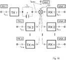
In einer Ausführungsform ist der Multiplexer in einem mobilen Kommunikationsgerät mit einem weiteren Filter oder Multiplexer und mit zwei Antennen enthalten. Der Multiplexer leitet Blockersignale, die von einer Antenne in die andere Antenne eingekoppelt werden, gegen Masse ab. Ein solcher Multiplexer eignet sich somit für mobile Kommunikationsgeräte mit Diversity-Funktionalität. Ein Sendesignal des Multiplexers kann aus einer mit dem Multiplexer verschalteten Antenne in eine weitere Diversity-Antenne zusammen mit einem externen Blockersignal eingekoppelt werden. Dies kann in einem weiteren Multiplexer, der mit der weiteren /Diversity-Antenne verschaltet ist, zu unerwünschten Intermodulationsprodukten führen. Um dies zu verhindern, ist es möglich, dass der Multiplexer oder weitere Multiplexer Blockerpfade aufweisen, die Blockersignale bezüglich jeweils anderer Multiplexer gegen Masse ableiten. Solche Blockerpfade können im Multiplexer oder in weiteren Multiplexern vorgesehen sein.In one embodiment, the multiplexer is included in a mobile communication device with another filter or multiplexer and with two antennas. The multiplexer conducts blocking signals coupled from one antenna to the other antenna to ground. Such a multiplexer is thus suitable for mobile communication devices with diversity functionality. A transmission signal of the multiplexer can be coupled from an antenna connected to the multiplexer in another diversity antenna together with an external blocking signal. This can result in unwanted intermodulation products in another multiplexer connected to the further / diversity antenna. In order to prevent this, it is possible for the multiplexer or further multiplexers to have blocker paths which derive blocking signals with respect to other multiplexers in each case to ground. Such blocker paths may be provided in the multiplexer or in further multiplexers.
In einer Ausführungsform umfasst das mobile Kommunikationsgerät als weiteres Filter ein Empfangsfilter für GPS-, Glonass-, Galileo-, oder Compass-Signale.In one embodiment, the mobile communication device includes as a further filter a receive filter for GPS, Glonass, Galileo, or Compass signals.
In einer Ausführungsform ist das weitere Filter ein bidirektionales Einzelfilter, das zum Beispiel für die Anwendungsgebiete Bluetooth oder WLAN vorgesehen sein kann.In one embodiment, the further filter is a bidirectional single filter, which may be provided for example for the application areas Bluetooth or WLAN.
In einer Ausführungsform des Multiplexers ist der Multiplexer in einem mobilen Kommunikationsgerät mit einem weiteren Filter oder Multiplexer verschaltet. Der Multiplexer ist dazu vorgesehen, Blocksignale, die über eine mit dem Multiplexer verschaltete Antenne in eine mit einem anderen Signalpfad verschaltete Antenne des Kommunikationsgerätes eingekoppelt werden würden, gegen Masse abzuleiten. Der Multiplexer sorgt so dafür, dass Blockersignale, die in anderen Multiplexern zu Störungen führen würden, gegen Masse abgeleitet werden.In one embodiment of the multiplexer, the multiplexer in a mobile communication device is connected to a further filter or multiplexer. The multiplexer is designed to divert block signals which would be coupled via an antenna connected to the multiplexer in an interconnected with another signal path antenna of the communication device to ground. The multiplexer thus ensures that blocking signals which would lead to interference in other multiplexers are diverted to ground.
In einer Ausführungsform ist der Multiplexer in einem mobilen Kommunikationsgerät verschaltet, wobei das mobile Kommunikationsgerät ein weiteres Filter oder einen weiteren Multiplexer umfasst. Der Multiplexer ist dann dazu vorgesehen, Blockersignale, die durch Übersprechen in einen anderen Signalpfad des Kommunikationsgerätes eingekoppelt werden würden gegen Masse abzuleiten. Neben der oben genannten Möglichkeit, dass Blockersignale ohne entsprechend ausgelegte Blockerpfade über Antennen in andere Signalpfade eines Kommunikationsgeräts gelangen können, ist nun eine Möglichkeit angegeben, Blockersignale, die innerhalb des mobilen Kommunikationsgeräts durch Übersprechen in andere Signalpfade eingekoppelt werden würden, zu neutralisieren.In one embodiment, the multiplexer is interconnected in a mobile communication device, wherein the mobile communication device comprises a further filter or another multiplexer. The multiplexer is then provided to derive blocker signals which would be coupled by crosstalk in another signal path of the communication device to ground. In addition to the above-mentioned possibility that blocker signals can pass through without antennas in other signal paths of a communication device without appropriately designed blocker paths, now a way to neutralize blocker signals that would be injected within the mobile communication device by crosstalk in other signal paths to neutralize.
In einer Ausführungsform des Multiplexers sind die Signalpfade zur Trennung durch Hochpass-, Tiefpass-, Bandpass- oder Bandsperrfilter an einem Antennenknoten verschaltet.In one embodiment of the multiplexer, the signal paths are interconnected by highpass, lowpass, bandpass or bandstop filters at an antenna node for isolation.
In einer Ausführungsform umfasst der Multiplexer ein weiteres Filter, welches das oben genannte weitere Filter oder ein zweites weiteres Filter sein kann. Das weitere Filter ist ein Empfangsfilter für GPS-, Glonass-, Galileo- oder Compass-Signale.In one embodiment, the multiplexer comprises a further filter, which may be the above-mentioned further filter or a second further filter. The other filter is a receive filter for GPS, Glonass, Galileo or Compass signals.
In einer Ausführungsform ist das Bandsperrfilter ein bidirektionales Einzelfilter.In one embodiment, the band rejection filter is a bidirectional single filter.
In einer Ausführungsform folgt dem Bandsperrfilter auf der von der Antenne abgewandten Seite ein weiteres Filter oder ein weiterer Multiplexer.In one embodiment, the band-stop filter on the side facing away from the antenna another filter or another multiplexer follows.
In einer Ausführungsform ist der Multiplexer in einem Kommunikationsgerät mit einem oder mehreren weiteren Multiplexern und zwei oder mehreren zugehörigen Antennen verschaltet.In one embodiment, the multiplexer in a communication device is interconnected with one or more other multiplexers and two or more associated antennas.
In einer Ausführungsform leitet der Multiplexer Blockersignale von außen und/oder Signale aufgrund von direktem Übersprechen zwischen den Antennen aus anderen Multiplexern ab. Abgeleitet werden insbesondere solche Signale, die zusammen oder mit eigenen Sendesignalen störende Intermodulationsprodukte erzeugen würden, wenn sie nicht abgeleitet werden würden.In one embodiment, the multiplexer derives external blocking signals and / or signals due to direct crosstalk between the antennas from other multiplexers. In particular, those signals are derived which together with their own transmission signals would produce interfering intermodulation products if they were not derived.
In einer Ausführungsform leitet der Multiplexer Blockersignale von außen und/oder Signale aufgrund von direktem Übersprechen im eigenen Gerät, welche aus anderen Multiplexern des Geräts stammen können, ab. Diese Signale würden, wenn sie nicht abgeleitet werden würden, zusammen oder mit eigenen Sendesignale störende Intermodulationsprodukte erzeugen.In one embodiment, the multiplexer routes external blocking signals and / or signals due to direct crosstalk in the own device, which may originate from other multiplexers of the device, from. These signals, if they were not derived, would produce interfering intermodulation products together or with their own transmit signals.
In einer Ausführungsform umfasst der Multiplexer einen oder mehrere Blockerpfade zur Eliminierung solcher Intermodulationsprodukte, die zwar nicht im eigenen Multiplexer stören, aber über die eigene Antenne abgestrahlt werden könnten in eine der anderen Antennen einkoppeln könnten und dort in angeschlossenen Multiplexern Störungen verursachen könnten.In one embodiment, the multiplexer includes one or more blocker paths for eliminating such intermodulation products that, while not interfering with their own multiplexer but capable of being radiated over their own antenna, could be coupled into one of the other antennas and interfere with connected multiplexers.
In einer Ausführungsform umfasst der Multiplexer einen oder mehrere Blockerpfade zur Eliminierung von Intermodulationsprodukten, die zwar nicht im eigenen Multiplexer aber durch direktes Übersprechen im Gerät in anderen Multiplexern stören würden.In one embodiment, the multiplexer includes one or more blocker paths for eliminating intermodulation products that would not interfere in their own multiplexer but by direct crosstalk in the device in other multiplexers.
In einer Ausführungsform ist mindestens einem Sende- oder Empfangsfilter in den Sende- oder Empfangspfaden ein Hochpass-, Tiefpass-, Bandpass- oder Bandsperrfilter niedriger Ordnung antennenseitig vorgeschaltet.In one embodiment, at least one transmit or receive filter in the transmit or receive path, a high-pass, low-pass, band-pass or band-stop filter low-order upstream of the antenna side.
In einer Ausführungsform dieses Multiplexers ist zumindest eines oder mehrere oder alle der Hochpass-, Tiefpass-, Bandpass- oder Bandsperrfilter niedriger Ordnung aus kapazitiven und/oder induktiven Elementen aufgebaut.In one embodiment of this multiplexer, at least one or more or all of the low-pass, low-pass, band-pass or band-stop filters are constructed of capacitive and / or inductive elements.
In einer Ausführungsform ist in mindestens einem Signalpfad nur das Filter niedriger Ordnung mit einem oder mehreren Blockerpfaden enthalten.In one embodiment, at least one signal path contains only the low-order filter with one or more blocker paths.
In einer Ausführungsform des Multiplexer ist in mindestens einem Signalpfad nur das Filter niedriger Ordnung ohne Blockerpfade enthalten.In one embodiment of the multiplexer, only the low-order filter without blocker paths is contained in at least one signal path.
In einer Ausführungsform ist der Multiplexer ein Diplexer, Triplexer, Quadplexer oder Quintplexer oder ein höherwertiger Multiplexer.In one embodiment, the multiplexer is a diplexer, triplexer, quadplexer or quintplexer, or a high-order multiplexer.
Im Folgenden wird der Multiplexer anhand von Ausführungsbeispielen und schematischen Figuren näher erläutert.The multiplexer will be explained in more detail below on the basis of exemplary embodiments and schematic figures.
Es zeigen:
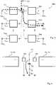
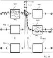
1A eine Chipoberfläche mit darauf angeordneten Fingerelektroden eines Interdigitalwandlers,1B eine Chipoberfläche mit einem darauf angeordneten BAW-Resonator,2A einen Multiplexer mit einem kapazitivem Element in einem Sendefilter,2B einen Multiplexer mit einem kapazitiven Element in einem Empfangsfilter,2C einen Multiplexer, bei dem ein gemeinsamer Anschluss über ein kapazitives Element mit Masse verschaltet ist,3 einen Multiplexer und typische Signalwege von Intermodulationsprodukten,4 einen Multiplexer mit einem Serienschwingkreis in einem Blockerpfad,5 einen Multiplexer mit einem elektroakustischen Resonator in einem Blockerpfad,6 einen Multiplexer mit einem akustischen Resonator und einem induktiven Element in einem Blockerpfad,7 einen Multiplexer mit gedoppelt ausgeführten Resonatoren in einem Sende- oder Empfangsfilter,8 das Ersatzschaltbild eines akustischen Resonators,9 einen Multiplexer mit einem Parallelzweigresonator im Blockerpfad eines Sende- oder Empfangsfilters,10 einen Multiplexer mit einem Serienzweigresonator und einem Parallelzweigresonator in einem Sende- oder Empfangsfilter,11 einen Multiplexer mit zwei induktiven Elementen und einem elektroakustischen Resonator in einem Blockerpfad,12 einen Multiplexer mit zwei induktiven Elementen und zwei elektroakustischen Resonatoren in einem Blockerpfad,13 zeigt schematisch eine Ausführungsform, bei der ein Sendefilter ein Notchfilter ist,14 zeigt schematisch den Einsatz eines Multiplexers in einem mobilen Kommunikationsgerät mit mehr als einer Antenne,15 zeigt eine Ausgestaltung eines Multiplexers, wobei zwischen einem Antennenanschluss ANT und dem gemeinsamen Anschluss CC ein Sperrkreis aus einer Induktivität L und einer On-Chip-Kapazität X verschaltet ist,16 zeigt eine Ausgestaltung eines Multiplexers mit einem Sperrkreis zwischen dem gemeinsamen Anschluss CC und einem Filter im Sendepfad.
1A a chip surface having thereon finger electrodes of an interdigital transducer,1B a chip surface having a BAW resonator disposed thereon,2A a multiplexer with a capacitive element in a transmit filter,2 B a multiplexer with a capacitive element in a receiving filter,2C a multiplexer in which a common connection is connected to ground via a capacitive element,3 a multiplexer and typical signal paths of intermodulation products,4 a multiplexer with a series resonant circuit in a blocker path,5 a multiplexer having an electroacoustic resonator in a blocker path,6 a multiplexer having an acoustic resonator and an inductive element in a blocker path,7 a multiplexer with doubled resonators in a transmit or receive filter,8th the equivalent circuit of an acoustic resonator,9 a multiplexer with a parallel branch resonator in the blocker path of a transmit or receive filter,10 a multiplexer having a series branch resonator and a parallel branch resonator in a transmitting or receiving filter,11 a multiplexer with two inductive elements and an electroacoustic resonator in a blocker path,12 a multiplexer with two inductive elements and two electroacoustic resonators in a blocker path,13 schematically shows an embodiment in which a transmission filter is a notch filter,14 shows schematically the use of a multiplexer in a mobile communication device with more than one antenna,15 shows an embodiment of a multiplexer, wherein between an antenna terminal ANT and the common terminal CC, a blocking circuit of an inductance L and an on-chip capacitance X is connected,16 shows an embodiment of a multiplexer with a blocking circuit between the common terminal CC and a filter in the transmission path.
Der Duplexer kann mit akustischen Oberflächenwellen arbeiten. Dann umfasst er weitere
Der Lagenstapel des BAW-Resonators
Exemplarisch ist gezeigt, wie Sendesignale des ersten Sendesignalpfads aus dem ersten Sendefilter
Der zentrale Erfindungsgedanke ist es entsprechend, Blockersignale der Frequenz FBlocker über den Blockerpfad so gegen Masse abzuleiten, dass ein Mischen mit den Sendesignalen aus dem ersten Empfangsfilter
Dann nämlich kann das zweite Empfangsfilter
Dies ist lediglich eine beispielhafte Ausführungsform eines Multiplexers. Es ist auch möglich, einen Multiplexer zu erhalten, in dem Duplexer, Triplexer, ... kaskadiert ausgeführt sind.This is merely an exemplary embodiment of a multiplexer. It is also possible to obtain a multiplexer in which duplexers, triplexers, ... are cascaded.
Das kapazitive Element
Bei paralleler Doppelung können Durchkontaktierungen
Es ist auch möglich, dass parallel gedoppelte Resonatoren zusätzlich in Serie gedoppelt ausgeführt sind.It is also possible that parallel-doubled resonators are additionally doubled in series.
Je nach Dimensionierung des elektroakustischen Resonators
So kann vorgesehen werden, dass speziell in Empfangspfaden für von Satelliten zu empfangende Navigationsdaten ungestört empfangen werden können.Thus, it can be provided that it is possible to receive undisturbed especially in receiving paths for navigation data to be received by satellites.
BezugszeichenlisteLIST OF REFERENCE NUMBERS
- ANT, ANT2:ANT, ANT2:
- Antenneantenna
- BAWR:BAWRs:
- BAW-ResonatorBAW resonator
- BP:BP:
- Blockerpfadblocker path
- C0:C0:
- statische Kapazitätstatic capacity
- CC:CC:
- gemeinsamer Anschlusscommon connection
- CC2:CC2:
- gemeinsamer Anschluss des zweiten Multiplexerscommon connection of the second multiplexer
- CD:CD:
- dynamische Kapazitätdynamic capacity
- CE:CE:
- kapazitives Elementcapacitive element
- CE2:CE2:
- weiteres kapazitives Elementanother capacitive element
- CH:CH:
- Chipchip
- ECD:ECD:
- ErsatzschaltbildEquivalent circuit
- EFI:EFI:
- Elektrodenfingerelectrode fingers
- EL1, EL2:EL1, EL2:
- Elektrodenelectrodes
- FBlocker:FBlocker:
- Blockerfrequenzblocker frequency
- FRx2, FRx2, FRxn:FRx2, FRx2, FRxn:
- Empfangsfrequenzenreceiving frequencies
- FTx1, FTx2, FTxm:FTx1, FTx2, FTxm:
- Sendefrequenzentransmission frequencies
- FTxm1:FTxm1:
- von einer Antenne in die andere Antenne eingekoppeltes Signal, welches bereits ein störendes Intermodulationsprodukt ist oder in der anderen Antenne zu einem störenden Intermodulationsprodukt führt.from one antenna into the other antenna coupled signal, which is already a disturbing intermodulation product or leads in the other antenna to a disturbing intermodulation product.
- GND:GND:
- MasseDimensions
- IDS:IDS:
- InterdigitalstrukturInterdigital structure
- IE:IE:
- induktives Elementinductive element
- IE2:IE2:
- weiteres, zweites induktives Elementanother, second inductive element
- LD:LD:
- dynamische Induktivitätdynamic inductance
- MN:MN:
- Anpassnetzwerkmatching
- MUL, MUL2:MUL, MUL2:
- Multiplexer, zweiter, weiterer MultiplexerMultiplexer, second, further multiplexer
- NOD:NOD:
- Knotenpunktjunction
- PL:PL:
- dielektrische Schichtdielectric layer
- R:R:
- (elektroakustischer) Resonator(electroacoustic) resonator
- Rx:Rx:
- Empfangsfilterreceive filter
- Rx1, Rx2:Rx1, Rx2:
- Empfangsfilterreceive filter
- RxC, Rxn:RxC, Rxn:
- Empfangsanschlussreceiving terminal
- RxC1, RxC2, RxCn:RxC1, RxC2, RxCn:
- Empfangsanschlussreceiving terminal
- SAWR: SAW-SAWR: SAW
- Resonatorresonator
- Tx:Tx:
- Sendefiltertransmission filter
- Tx1, Tx2, Txm:Tx1, Tx2, Txm:
- Sendefiltertransmission filter
- TxC:TxC:
- Sendeanschlusstransmitting terminal
- TxC1, TxC2, TxCm:TxC1, TxC2, TxCm:
- Sendeanschlusstransmitting terminal
- VIA:VIA:
- Durchkontaktierung (Via)Via (via)
Claims (44)
Translated fromGermanPriority Applications (6)
| Application Number | Priority Date | Filing Date | Title |
|---|---|---|---|
| DE102012108030.5ADE102012108030B4 (en) | 2012-08-30 | 2012-08-30 | Multiplexer with reduced intermodulation products |
| EP13742458.6AEP2891244A1 (en) | 2012-08-30 | 2013-07-30 | Multiplexer having fewer intermodulation products |
| US14/424,982US9985607B2 (en) | 2012-08-30 | 2013-07-30 | Multiplexer having fewer intermodulation products |
| PCT/EP2013/066014WO2014032889A1 (en) | 2012-08-30 | 2013-07-30 | Multiplexer having fewer intermodulation products |
| KR1020157008169AKR20150048867A (en) | 2012-08-30 | 2013-07-30 | Multiplexer having fewer intermodulation products |
| JP2015528932AJP6342897B2 (en) | 2012-08-30 | 2013-07-30 | Multiplexer with reduced intermodulation products |
Applications Claiming Priority (1)
| Application Number | Priority Date | Filing Date | Title |
|---|---|---|---|
| DE102012108030.5ADE102012108030B4 (en) | 2012-08-30 | 2012-08-30 | Multiplexer with reduced intermodulation products |
Publications (2)
| Publication Number | Publication Date |
|---|---|
| DE102012108030A1 DE102012108030A1 (en) | 2014-03-06 |
| DE102012108030B4true DE102012108030B4 (en) | 2018-05-09 |
Family
ID=48900992
Family Applications (1)
| Application Number | Title | Priority Date | Filing Date |
|---|---|---|---|
| DE102012108030.5AExpired - Fee RelatedDE102012108030B4 (en) | 2012-08-30 | 2012-08-30 | Multiplexer with reduced intermodulation products |
Country Status (6)
| Country | Link |
|---|---|
| US (1) | US9985607B2 (en) |
| EP (1) | EP2891244A1 (en) |
| JP (1) | JP6342897B2 (en) |
| KR (1) | KR20150048867A (en) |
| DE (1) | DE102012108030B4 (en) |
| WO (1) | WO2014032889A1 (en) |
Families Citing this family (19)
| Publication number | Priority date | Publication date | Assignee | Title |
|---|---|---|---|---|
| WO2015056685A1 (en)* | 2013-10-16 | 2015-04-23 | 株式会社村田製作所 | Transmission-reception device |
| US10784723B2 (en)* | 2015-05-12 | 2020-09-22 | The Regents Of The University Of Michigan | Nonlinear resonance circuit for wireless power transmission and wireless power harvesting |
| DE102015108511B3 (en)* | 2015-05-29 | 2016-09-22 | Epcos Ag | multiplexer |
| US10707905B2 (en)* | 2015-06-23 | 2020-07-07 | Skyworks Solutions, Inc. | Wideband multiplexer for radio-frequency applications |
| JP6573851B2 (en)* | 2016-08-04 | 2019-09-11 | 太陽誘電株式会社 | Multiplexer |
| US10541673B2 (en) | 2016-10-28 | 2020-01-21 | Skyworks Solutions, Inc. | Acoustic wave filter including two types of acoustic wave resonators |
| KR102565276B1 (en)* | 2016-11-16 | 2023-08-09 | 삼성전자주식회사 | Wireless device with shared coil |
| WO2018168655A1 (en) | 2017-03-15 | 2018-09-20 | 株式会社村田製作所 | Multiplexer, high frequency front end circuit, and communication device |
| US10193509B1 (en) | 2017-07-28 | 2019-01-29 | Avago Technologies International Sales Pte. Limited | Power amplifier harmonic matching network |
| US11368179B2 (en)* | 2017-10-17 | 2022-06-21 | Skyworks Solutions, Inc. | Modulation partitioning and transmission via multiple antennas for enhanced transmit power capability |
| WO2019131501A1 (en)* | 2017-12-25 | 2019-07-04 | 株式会社村田製作所 | Multiplexer |
| SG10201902753RA (en)* | 2018-04-12 | 2019-11-28 | Skyworks Solutions Inc | Filter Including Two Types Of Acoustic Wave Resonators |
| KR102702956B1 (en)* | 2018-07-01 | 2024-09-04 | 프리드리히-알렉산더-우니베르지테트 에를랑겐-뉘른베르크 | Electromagnetic interference suppression components |
| EP3591819A1 (en)* | 2018-07-06 | 2020-01-08 | Friedrich-Alexander-Universität Erlangen-Nürnberg | Electromagnetic interference suppression components |
| JP7014308B2 (en)* | 2018-11-20 | 2022-02-01 | 株式会社村田製作所 | Extractor |
| JP6939763B2 (en)* | 2018-12-25 | 2021-09-22 | 株式会社村田製作所 | Multiplexers, high frequency front-end circuits, and communication equipment |
| DE102019120312A1 (en) | 2019-07-26 | 2021-01-28 | RF360 Europe GmbH | A filter device comprising two connected filter circuits |
| US11621697B2 (en)* | 2019-09-09 | 2023-04-04 | Skyworks Global Pte. Ltd. | Harmonic suppression in bulk acoustic wave duplexer |
| KR102783970B1 (en)* | 2019-09-27 | 2025-03-19 | 가부시키가이샤 무라타 세이사쿠쇼 | Elastic wave devices, filter devices and multiplexers |
Citations (3)
| Publication number | Priority date | Publication date | Assignee | Title |
|---|---|---|---|---|
| DE102005028927A1 (en) | 2005-06-22 | 2006-12-28 | Infineon Technologies Ag | Bulk acoustic wave apparatus for use in mobile radio system, has two bulk acoustic wave resonators connected in antiparallel, such that resonators have same polarization direction |
| US20080024243A1 (en) | 2006-06-19 | 2008-01-31 | Fujitsu Media Devices Limited | Duplexer |
| JP2011193080A (en) | 2010-03-12 | 2011-09-29 | Ube Industries Ltd | Branching filter |
Family Cites Families (22)
| Publication number | Priority date | Publication date | Assignee | Title |
|---|---|---|---|---|
| JP3794897B2 (en) | 2000-03-30 | 2006-07-12 | シャープ株式会社 | Wireless communication device |
| US6407649B1 (en)* | 2001-01-05 | 2002-06-18 | Nokia Corporation | Monolithic FBAR duplexer and method of making the same |
| DE10296803B4 (en) | 2001-05-11 | 2008-04-10 | Ube Industries, Ltd., Ube | Duplexer with FBAR balance resonator |
| JP3940887B2 (en) | 2001-05-11 | 2007-07-04 | 宇部興産株式会社 | A duplexer using a thin film piezoelectric resonator. |
| JP2006135447A (en) | 2004-11-02 | 2006-05-25 | Fujitsu Media Device Kk | Duplexer |
| WO2007000929A1 (en)* | 2005-06-29 | 2007-01-04 | Matsushita Electric Industrial Co., Ltd. | Piezoelectric resonator, piezoelectric filter, resonator and communication device using the same |
| JP2007060411A (en)* | 2005-08-25 | 2007-03-08 | Fujitsu Media Device Kk | Duplexer |
| DE102006022580B4 (en)* | 2006-05-15 | 2014-10-09 | Epcos Ag | Electrical component |
| DE102006031548A1 (en)* | 2006-07-07 | 2008-01-17 | Epcos Ag | Transmission receiver circuit, has duplexer with transmission band for transmitting signals and receiver band for receiving signals, where antenna circuit is connected at duplexer |
| US7535323B2 (en)* | 2006-07-10 | 2009-05-19 | Skyworks Solutions, Inc. | Bulk acoustic wave filter with reduced nonlinear signal distortion |
| DE102006033709B4 (en)* | 2006-07-20 | 2010-01-14 | Epcos Ag | Electric module |
| JP5072047B2 (en)* | 2007-08-23 | 2012-11-14 | 太陽誘電株式会社 | Elastic wave filter, duplexer using the same, and communication device using the duplexer |
| JP4586897B2 (en)* | 2008-06-24 | 2010-11-24 | 株式会社村田製作所 | Duplexer |
| JP5262413B2 (en)* | 2008-08-12 | 2013-08-14 | 株式会社村田製作所 | Multiband duplexer module |
| DE102008045346B4 (en)* | 2008-09-01 | 2018-06-07 | Snaptrack Inc. | Duplexer and method for increasing the isolation between two filters |
| JP2010109894A (en)* | 2008-10-31 | 2010-05-13 | Fujitsu Ltd | Acoustic wave filter, duplexer, communication module, and communication apparatus |
| SG183135A1 (en)* | 2010-02-04 | 2012-09-27 | Taiyo Yuden Kk | Filter, duplexer, communication module, communication device |
| JP2011211347A (en)* | 2010-03-29 | 2011-10-20 | Ube Industries Ltd | Piezoelectric device, integrated branching filter using the same, and integrated filter |
| WO2012020595A1 (en)* | 2010-08-11 | 2012-02-16 | 株式会社村田製作所 | High frequency module and communication device |
| JP2012147175A (en)* | 2011-01-11 | 2012-08-02 | Murata Mfg Co Ltd | Acoustic wave demultiplexer |
| JP5522068B2 (en)* | 2011-01-25 | 2014-06-18 | カシオ計算機株式会社 | Image display device, image display method, and program |
| CN103907286B (en)* | 2011-10-24 | 2016-08-24 | 株式会社村田制作所 | elastic wave splitter |
- 2012
- 2012-08-30DEDE102012108030.5Apatent/DE102012108030B4/ennot_activeExpired - Fee Related
- 2013
- 2013-07-30WOPCT/EP2013/066014patent/WO2014032889A1/enactiveApplication Filing
- 2013-07-30KRKR1020157008169Apatent/KR20150048867A/ennot_activeCeased
- 2013-07-30USUS14/424,982patent/US9985607B2/ennot_activeExpired - Fee Related
- 2013-07-30JPJP2015528932Apatent/JP6342897B2/ennot_activeExpired - Fee Related
- 2013-07-30EPEP13742458.6Apatent/EP2891244A1/ennot_activeWithdrawn
Patent Citations (3)
| Publication number | Priority date | Publication date | Assignee | Title |
|---|---|---|---|---|
| DE102005028927A1 (en) | 2005-06-22 | 2006-12-28 | Infineon Technologies Ag | Bulk acoustic wave apparatus for use in mobile radio system, has two bulk acoustic wave resonators connected in antiparallel, such that resonators have same polarization direction |
| US20080024243A1 (en) | 2006-06-19 | 2008-01-31 | Fujitsu Media Devices Limited | Duplexer |
| JP2011193080A (en) | 2010-03-12 | 2011-09-29 | Ube Industries Ltd | Branching filter |
Also Published As
| Publication number | Publication date |
|---|---|
| DE102012108030A1 (en) | 2014-03-06 |
| JP2015531221A (en) | 2015-10-29 |
| US20150236840A1 (en) | 2015-08-20 |
| US9985607B2 (en) | 2018-05-29 |
| KR20150048867A (en) | 2015-05-07 |
| JP6342897B2 (en) | 2018-06-13 |
| WO2014032889A1 (en) | 2014-03-06 |
| EP2891244A1 (en) | 2015-07-08 |
Similar Documents
| Publication | Publication Date | Title |
|---|---|---|
| DE102012108030B4 (en) | Multiplexer with reduced intermodulation products | |
| DE112016002335B4 (en) | Multiplexer, transmitting device, receiving device, high frequency front-end circuit, communication device, and impedance matching method for a multiplexer | |
| DE102017125774B4 (en) | multiplexer | |
| DE102012223187B4 (en) | System and method for a high frequency switch | |
| DE102016103457B4 (en) | Combined passband acoustic filter device | |
| DE102007024895B4 (en) | Multiband filter | |
| DE102009011639B4 (en) | Reactance filter with steep edge and its use as a transmit filter in a duplexer | |
| DE102018104118A1 (en) | Multiplexer, transmitter and receiver | |
| DE102008052222B4 (en) | Antenna duplexer with high GPS suppression | |
| DE102016112993B4 (en) | Notch filter as well as this comprehensive extractor arrangement | |
| DE102018102891A1 (en) | Multiplexer, transmission device and receiving device | |
| DE102005051852B4 (en) | SAW filter with broadband bandstop filter | |
| DE102014112676A1 (en) | Filter with improved linearity | |
| DE102007033233B4 (en) | High pass filter and use | |
| EP3292634A1 (en) | Hf circuit and hf module | |
| DE102016122000A1 (en) | Multiplexer with improved isolation, module comprising a multiplexer and a method for designing a multiplexer topology | |
| DE60316457T2 (en) | Thin film resonator ladder filter and method of grounding these filters | |
| DE102019119677B4 (en) | RF receive filters, RF duplexers and RF multiplexers | |
| DE102014102704A1 (en) | Combined impedance matching and RF filter circuit | |
| DE102006005298A1 (en) | duplexer | |
| DE102010055648B4 (en) | filter device | |
| DE102005045372A1 (en) | Component with at least one working with acoustic waves filter | |
| DE102010011649B4 (en) | Front-end circuit for a mobile communication device with improved impedance matching | |
| DE102018111428A1 (en) | RF multiplexer | |
| WO2017036673A1 (en) | Saw filter |
Legal Events
| Date | Code | Title | Description |
|---|---|---|---|
| R012 | Request for examination validly filed | ||
| R016 | Response to examination communication | ||
| R016 | Response to examination communication | ||
| R081 | Change of applicant/patentee | Owner name:SNAPTRACK, INC., SAN DIEGO, US Free format text:FORMER OWNER: EPCOS AG, 81669 MUENCHEN, DE | |
| R082 | Change of representative | Representative=s name:BARDEHLE PAGENBERG PARTNERSCHAFT MBB PATENTANW, DE | |
| R018 | Grant decision by examination section/examining division | ||
| R020 | Patent grant now final | ||
| R119 | Application deemed withdrawn, or ip right lapsed, due to non-payment of renewal fee |