DE102012106336A1 - Bone screw for use in bone fixation system for connecting two bone portions, has distal screw part and proximal screw part, where distal screw part has distal bone thread, and proximal screw part has proximal bone thread - Google Patents
Bone screw for use in bone fixation system for connecting two bone portions, has distal screw part and proximal screw part, where distal screw part has distal bone thread, and proximal screw part has proximal bone threadDownload PDFInfo
- Publication number
- DE102012106336A1 DE102012106336A1DE201210106336DE102012106336ADE102012106336A1DE 102012106336 A1DE102012106336 A1DE 102012106336A1DE 201210106336DE201210106336DE 201210106336DE 102012106336 ADE102012106336 ADE 102012106336ADE 102012106336 A1DE102012106336 A1DE 102012106336A1
- Authority
- DE
- Germany
- Prior art keywords
- proximal
- bone
- screw part
- distal
- screw
- Prior art date
- Legal status (The legal status is an assumption and is not a legal conclusion. Google has not performed a legal analysis and makes no representation as to the accuracy of the status listed.)
- Withdrawn
Links
- 210000000988bone and boneAnatomy0.000titleclaimsabstractdescription239
- 230000008878couplingEffects0.000claimsabstractdescription166
- 238000010168coupling processMethods0.000claimsabstractdescription166
- 238000005859coupling reactionMethods0.000claimsabstractdescription166
- 125000006850spacer groupChemical group0.000claimsdescription82
- 238000006073displacement reactionMethods0.000claimsdescription16
- 239000000463materialSubstances0.000claimsdescription6
- 229920000159gelatinPolymers0.000claimsdescription5
- 235000019322gelatineNutrition0.000claimsdescription5
- 108010010803GelatinProteins0.000claimsdescription4
- 239000008273gelatinSubstances0.000claimsdescription4
- 235000011852gelatine dessertsNutrition0.000claimsdescription4
- 208000010392Bone FracturesDiseases0.000description7
- 206010017076FractureDiseases0.000description7
- 230000002349favourable effectEffects0.000description7
- 239000012634fragmentSubstances0.000description4
- 210000004095humeral headAnatomy0.000description4
- 230000035515penetrationEffects0.000description3
- 238000004026adhesive bondingMethods0.000description2
- 238000010276constructionMethods0.000description2
- 238000002513implantationMethods0.000description2
- 229920000747poly(lactic acid)Polymers0.000description2
- 238000005476solderingMethods0.000description2
- 238000003466weldingMethods0.000description2
- 239000001828GelatineSubstances0.000description1
- 241000209035IlexSpecies0.000description1
- 208000002103Shoulder FracturesDiseases0.000description1
- 238000010521absorption reactionMethods0.000description1
- 239000000560biocompatible materialSubstances0.000description1
- 230000006835compressionEffects0.000description1
- 238000007906compressionMethods0.000description1
- 230000009977dual effectEffects0.000description1
- 230000000694effectsEffects0.000description1
- 210000002758humerusAnatomy0.000description1
- 238000004519manufacturing processMethods0.000description1
- 238000000926separation methodMethods0.000description1
- 210000000323shoulder jointAnatomy0.000description1
- 239000002689soilSubstances0.000description1
- 230000001360synchronised effectEffects0.000description1
Images


Classifications
- A—HUMAN NECESSITIES
- A61—MEDICAL OR VETERINARY SCIENCE; HYGIENE
- A61B—DIAGNOSIS; SURGERY; IDENTIFICATION
- A61B17/00—Surgical instruments, devices or methods
- A61B17/56—Surgical instruments or methods for treatment of bones or joints; Devices specially adapted therefor
- A61B17/58—Surgical instruments or methods for treatment of bones or joints; Devices specially adapted therefor for osteosynthesis, e.g. bone plates, screws or setting implements
- A61B17/68—Internal fixation devices, including fasteners and spinal fixators, even if a part thereof projects from the skin
- A61B17/84—Fasteners therefor or fasteners being internal fixation devices
- A61B17/86—Pins or screws or threaded wires; nuts therefor
- A61B17/8625—Shanks, i.e. parts contacting bone tissue
- A61B17/863—Shanks, i.e. parts contacting bone tissue with thread interrupted or changing its form along shank, other than constant taper
- A—HUMAN NECESSITIES
- A61—MEDICAL OR VETERINARY SCIENCE; HYGIENE
- A61B—DIAGNOSIS; SURGERY; IDENTIFICATION
- A61B17/00—Surgical instruments, devices or methods
- A61B17/56—Surgical instruments or methods for treatment of bones or joints; Devices specially adapted therefor
- A61B17/58—Surgical instruments or methods for treatment of bones or joints; Devices specially adapted therefor for osteosynthesis, e.g. bone plates, screws or setting implements
- A61B17/68—Internal fixation devices, including fasteners and spinal fixators, even if a part thereof projects from the skin
- A61B17/84—Fasteners therefor or fasteners being internal fixation devices
- A61B17/86—Pins or screws or threaded wires; nuts therefor
- A61B17/8685—Pins or screws or threaded wires; nuts therefor comprising multiple separate parts
- A—HUMAN NECESSITIES
- A61—MEDICAL OR VETERINARY SCIENCE; HYGIENE
- A61B—DIAGNOSIS; SURGERY; IDENTIFICATION
- A61B17/00—Surgical instruments, devices or methods
- A61B17/56—Surgical instruments or methods for treatment of bones or joints; Devices specially adapted therefor
- A61B17/58—Surgical instruments or methods for treatment of bones or joints; Devices specially adapted therefor for osteosynthesis, e.g. bone plates, screws or setting implements
- A61B17/68—Internal fixation devices, including fasteners and spinal fixators, even if a part thereof projects from the skin
- A61B17/80—Cortical plates, i.e. bone plates; Instruments for holding or positioning cortical plates, or for compressing bones attached to cortical plates
- A61B17/8061—Cortical plates, i.e. bone plates; Instruments for holding or positioning cortical plates, or for compressing bones attached to cortical plates specially adapted for particular bones
- A—HUMAN NECESSITIES
- A61—MEDICAL OR VETERINARY SCIENCE; HYGIENE
- A61B—DIAGNOSIS; SURGERY; IDENTIFICATION
- A61B17/00—Surgical instruments, devices or methods
- A61B17/56—Surgical instruments or methods for treatment of bones or joints; Devices specially adapted therefor
- A61B17/58—Surgical instruments or methods for treatment of bones or joints; Devices specially adapted therefor for osteosynthesis, e.g. bone plates, screws or setting implements
- A61B17/68—Internal fixation devices, including fasteners and spinal fixators, even if a part thereof projects from the skin
- A61B17/84—Fasteners therefor or fasteners being internal fixation devices
- A61B17/86—Pins or screws or threaded wires; nuts therefor
- A61B17/8605—Heads, i.e. proximal ends projecting from bone
- A61B17/861—Heads, i.e. proximal ends projecting from bone specially shaped for gripping driver
- A61B17/8615—Heads, i.e. proximal ends projecting from bone specially shaped for gripping driver at the central region of the screw head
- A—HUMAN NECESSITIES
- A61—MEDICAL OR VETERINARY SCIENCE; HYGIENE
- A61B—DIAGNOSIS; SURGERY; IDENTIFICATION
- A61B17/00—Surgical instruments, devices or methods
- A61B17/56—Surgical instruments or methods for treatment of bones or joints; Devices specially adapted therefor
- A61B17/58—Surgical instruments or methods for treatment of bones or joints; Devices specially adapted therefor for osteosynthesis, e.g. bone plates, screws or setting implements
- A61B17/68—Internal fixation devices, including fasteners and spinal fixators, even if a part thereof projects from the skin
- A61B17/84—Fasteners therefor or fasteners being internal fixation devices
- A61B17/86—Pins or screws or threaded wires; nuts therefor
- A61B17/864—Pins or screws or threaded wires; nuts therefor hollow, e.g. with socket or cannulated
- A—HUMAN NECESSITIES
- A61—MEDICAL OR VETERINARY SCIENCE; HYGIENE
- A61B—DIAGNOSIS; SURGERY; IDENTIFICATION
- A61B17/00—Surgical instruments, devices or methods
- A61B17/56—Surgical instruments or methods for treatment of bones or joints; Devices specially adapted therefor
- A61B17/58—Surgical instruments or methods for treatment of bones or joints; Devices specially adapted therefor for osteosynthesis, e.g. bone plates, screws or setting implements
- A61B17/68—Internal fixation devices, including fasteners and spinal fixators, even if a part thereof projects from the skin
- A61B17/84—Fasteners therefor or fasteners being internal fixation devices
- A61B17/86—Pins or screws or threaded wires; nuts therefor
- A61B17/869—Pins or screws or threaded wires; nuts therefor characterised by an open form, e.g. wire helix
Landscapes
- Health & Medical Sciences (AREA)
- Orthopedic Medicine & Surgery (AREA)
- Surgery (AREA)
- Life Sciences & Earth Sciences (AREA)
- Heart & Thoracic Surgery (AREA)
- Nuclear Medicine, Radiotherapy & Molecular Imaging (AREA)
- Engineering & Computer Science (AREA)
- Biomedical Technology (AREA)
- Neurology (AREA)
- Medical Informatics (AREA)
- Molecular Biology (AREA)
- Animal Behavior & Ethology (AREA)
- General Health & Medical Sciences (AREA)
- Public Health (AREA)
- Veterinary Medicine (AREA)
- Surgical Instruments (AREA)
Abstract
Description
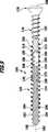
Translated fromGermanDie vorliegende Erfindung betrifft eine Knochenschraube mit einem distalen Schraubenteil und einem proximalen Schraubenteil, welcher distale Schraubenteil ein distales Knochengewinde umfasst und welcher proximale Schraubenteil ein proximales Knochengewinde umfasst, wobei der distale Schraubenteil und der proximale Schraubenteil relativ zueinander in einer Richtung parallel zu einer von der Knochenschraube definierten Längsachse verschiebbar sind.The present invention relates to a bone screw having a distal screw portion and a proximal screw portion, the distal screw portion includes a distal bone thread and which proximal screw portion includes a proximal bone thread, the distal screw portion and the proximal screw portion relative to each other in a direction parallel to one of the bone screw defined longitudinal axis are displaced.
Ferner betrifft die vorliegende Erfindung ein Knochenfixierungssystem zum Verbinden von mindestens zwei voneinander in Folge einer Fraktur getrennten Knochenteilen, umfassend mindestens eine mindestens eine Durchbrechung aufweisende Knochenplatte und mindestens eine durch die Durchbrechung mindestens teilweise durchführbare Knochenschraube, welche Knochenschraube einen distalen Schraubenteil und einen proximalen Schraubenteil umfasst, welcher distale Schraubenteil ein distales Knochengewinde umfasst und welcher proximale Schraubenteil ein proximales Knochengewinde umfasst, wobei der distale Schraubenteil und der proximale Schraubenteil relativ zueinander in einer Richtung parallel zu einer von der Knochenschraube definierten Längsachse verschiebbar sind.Furthermore, the present invention relates to a bone fixation system for connecting at least two bone parts separated from one another by a fracture, comprising at least one bone plate having at least one opening and at least one bone screw at least partially feasible through the opening, which bone screw comprises a distal screw part and a proximal screw part, which distal screw part comprises a distal bone thread and which proximal screw part comprises a proximal bone thread, wherein the distal screw part and the proximal screw part are displaceable relative to one another in a direction parallel to a longitudinal axis defined by the bone screw.
Knochenschrauben und Knochenfixierungssysteme der eingangs beschriebenen Art werden zur Behandlung von Knochenfrakturen eingesetzt, beispielsweise von proximalen Humerusfrakturen, insbesondere im Bereich des Schultergelenks. Dabei können glenohumerale Schraubenpenetrationen auftreten, die jedoch nicht erwünscht sind. Derartige Schraubenpenetrationen können intraoperativ erfolgen, beispielsweise wenn eine Schraubenlänge vom Operateur falsch beurteilt und diese entsprechend falsch, also zu lang, gewählt wird, sowie postoperativ durch Abkippen beziehungsweise Absinken des Kalottenfragments über Schraubenspitzen der Knochenschrauben.Bone screws and bone fixation systems of the type described above are used for the treatment of bone fractures, such as proximal humeral fractures, especially in the region of the shoulder joint. In this case, glenohumeral screw penetrations occur, but these are not desirable. Such Schraubenpenetrationen can be done intraoperatively, for example, if a screw length misjudged by the surgeon and this wrong, ie too long, is selected, as well as postoperatively by tipping or sinking the Kalottenfragments screw tips of the bone screws.
Um herkömmliche Knochenschrauben der eingangs beschriebenen Art, die auch als teleskopierbare Schrauben bezeichnet werden, in die miteinander zu verbindenden Knochenteile einschrauben zu können, müssen sowohl der distale Schraubenteil als auch der proximale Schraubenteil eine Werkzeugelementaufnahme aufweisen, so dass mit einem gekoppelten oder zwei Einschraubwerkzeugen die Knochenschraube in gewünschter Weise gesetzt werden kann. Ein Problem stellen insbesondere Schrauben mit relativ geringen Durchmessern dar, denn bei den teleskopierbaren Schrauben muss der proximale Schraubenteil kanüliert werden, um von proximal her kommend einen Zugriff auf das distale Schraubenteil zu ermöglichen. Je kleiner jedoch die den proximalen Schraubenteil durchsetzenden Kanäle sind, umso kleiner müssen auch die Werkzeugelemente beziehungsweise das Einschraubwerkzeug sein, welche aufgrund ihrer Größe dann eine maximal einleitbare Kraft beziehungsweise ein entsprechendes Drehmoment begrenzen. Insbesondere für die Explantation der Knochenschraube ist es wichtig, dass diese sicher entfernt werden kann, ohne die Werkzeugelementaufnahmen zu zerstören. Daher kann bei herkömmlichen teleskopierbaren Schrauben ein minimaler Schaftdurchmesser insbesondere des proximalen Schraubenteils nicht unterschritten werden, um eine hinreichende Stabilität der Knochenschraube gewährleisten zu können.In order to screw conventional bone screws of the type described above, which are also referred to as telescoping screws into the bone parts to be joined together, both the distal screw part and the proximal screw part must have a tool element receptacle, so that with a coupled or two Einschraubwerkzeugen the bone screw can be set in the desired manner. In particular screws with relatively small diameters represent a problem, because with the telescopic screws, the proximal screw part must be cannulated in order to allow access to the distal screw part coming from proximally. However, the smaller the passages passing through the proximal screw part, the smaller the tool elements or the screwing-in tool must be, which, due to their size, then limit a maximum force that can be introduced or a corresponding torque. In particular, for the explantation of the bone screw, it is important that it can be safely removed without destroying the tool element receptacles. Therefore, in conventional telescopic screws, a minimum shaft diameter, in particular of the proximal screw part, can not be undershot, in order to be able to ensure sufficient stability of the bone screw.
Es ist daher eine Aufgabe der vorliegenden Erfindung, eine Knochenschraube und ein Knochenfixierungssystem der eingangs beschriebenen Art so zu verbessern, dass auch bei geringen Schraubendurchmessern noch eine ausreichende Stabilität erreicht werden kann.It is therefore an object of the present invention to improve a bone screw and a bone fixation system of the type described above so that even with small screw diameters still sufficient stability can be achieved.
Die Aufgabe wird bei einer Knochenschraube der eingangs beschriebenen Art erfindungsgemäß dadurch gelöst, dass sie eine Drehkopplungseinrichtung zum drehfesten Koppeln des distalen Schraubenteils und des proximalen Schraubenteils in Umfangsrichtung umfasst.The object is achieved in a bone screw of the type described above according to the invention in that it comprises a rotary coupling device for rotationally fixed coupling of the distal screw part and the proximal screw part in the circumferential direction.
Die Drehkopplungseinrichtung ermöglicht es insbesondere, lediglich am proximalen Schraubenteil eine Werkzeugelementaufnahme vorzusehen, um die Knochenschraube in den Knochen einzuschrauben. Mittels der Drehkopplungseinrichtung wird infolge einer Rotation des proximalen Schraubenteils auch der distale Schraubenteil mit rotiert. Es erfolgt somit eine Drehkopplung in Umfangsrichtung. Die Drehkopplungseinrichtung hat so ferner auch die Funktion einer Mitnahmeeinrichtung, die es ermöglicht, infolge einer Rotation des proximalen Schraubenteils den distalen Schraubenteil sozusagen mitzunehmen, also gleichsinnig mit insbesondere derselben Rotationsgeschwindigkeit wie den proximalen Schraubenteil zu rotieren. Durch die Drehkopplungseinrichtung kann dann insbesondere auch auf eine Werkzeugelementaufnahme am distalen Schraubenteil verzichtet werden. Eine Kanülierung des proximalen Schraubenteils ist dann nicht mehr erforderlich, um Zugriff zum distalen Schraubenteil zu erhalten. Mit der erfindungsgemäß vorgeschlagenen Knochenschraube können der proximale und der distale Schraubenteil mit einem einzigen Einschraubwerkzeug eingeschraubt werden, welches lediglich mit dem proximalen Schraubenteil in Eingriff gebracht werden muss, was zudem die intraoperative Handhabung der Knochenschraube verbessert. Die Knochenschraube kann insbesondere zur Fixierung eines Humeruskopffragments eingesetzt werden. Dieses kann man sich als eine dünne Halbschale vorstellen. Daher ist es grundsätzlich günstig, diese Halbschale wie bei einem Regenschirm an mehreren Stellen gleichmäßig abzustützen. Nachträgliche Bewegungen des Humeruskopffragments können mit der vorgeschlagenen Knochenschraube ausgeglichen werden, ohne dass eine Schraubenpenetration entsteht, welche insbesondere dann auftreten kann, wenn ein Operateur herkömmliche starre Schrauben zur Fixierung des Knochenfragments verwendet und diese zu lang gewählt hat. Die erfindungsgemäß weitergebildete Knochenschraube ist somit bei der Operation sehr einfach handhabbar. Aufgrund der axialen Beweglichkeit der beiden Schraubenteile der Knochenschraube relativ zueinander verzeiht diese Knochenschraube Fehler, insbesondere wenn die Länge der Knochenschraube vom Operateur nicht exakt passend gewählt wurde.In particular, the rotary coupling device makes it possible to provide a tool element receptacle only at the proximal screw part in order to screw the bone screw into the bone. By means of the rotary coupling device, the distal screw part is also rotated due to a rotation of the proximal screw part. There is thus a rotary coupling in the circumferential direction. The rotary coupling device thus also has the function of a driving device, which makes it possible, so to speak, to take along the distal screw part as a result of rotation of the proximal screw part, ie to rotate in the same direction with, in particular, the same rotational speed as the proximal screw part. By the rotary coupling device can then be dispensed in particular on a tool element receiving the distal screw part. Cannulation of the proximal screw part is then no longer required to gain access to the distal screw part. With the bone screw proposed according to the invention, the proximal and distal screw parts can be screwed in with a single screw-in tool which only has to be engaged with the proximal screw part, which also improves the intraoperative handling of the bone screw. The bone screw can be used in particular for fixing a humeral head fragment. This can be thought of as a thin half shell. That's why it's basically favorable, evenly support this half shell as in an umbrella in several places. Subsequent movements of the humeral head fragment can be compensated with the proposed bone screw, without a screw penetration arises, which can occur in particular when a surgeon has used conventional rigid screws for fixation of the bone fragment and has chosen too long. The further developed according to the invention bone screw is thus very easy to handle during the operation. Due to the axial mobility of the two screw parts of the bone screw relative to each other, this bone screw forgives mistakes, especially if the length of the bone screw was not chosen by the surgeon exactly matching.
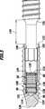
Günstigerweise umfasst die Drehkopplungseinrichtung mindestens ein Drehkopplungsglied, welches den distalen Schraubenteil und den proximalen Schraubenteil miteinander drehfest koppelt. Es ist insbesondere denkbar, ein einziges Drehkopplungsglied vorzusehen, um die beiden Schraubenteile miteinander drehfest zu koppeln.Conveniently, the rotary coupling device comprises at least one rotary coupling member which rotatably coupled to the distal screw member and the proximal screw member. It is particularly conceivable to provide a single rotary coupling member in order to couple the two screw parts with each other in a rotationally fixed manner.
Vorteilhaft ist, wenn die Drehkopplungseinrichtung mindestens zwei miteinander zusammenwirkende erste und zweite Drehkopplungsglieder umfasst, welche miteinander drehfest in Eingriff stehen. Insbesondere können zwei Drehkopplungsglieder vorgesehen sein, eines am proximalen Schraubenteil und eines am distalen Schraubenteil. Insbesondere kann das am proximalen Schraubenteil vorgesehene Drehkopplungsglied die Funktion eines Mitnehmers ausüben, um ein in das proximale Schraubenteil eingeleitetes Drehmoment auf den distalen Schraubenteil zu übertragen. Das Drehkopplungsglied des proximalen Schraubenteils übernimmt dann quasi die Funktion eines Werkzeugelements, welches mit dem anderen Drehkopplungsglied, welches quasi eine Werkzeugelementaufnahme des distalen Schraubenteils definiert, zusammenwirkt. In einem solchen Fall kann somit das proximale Schraubenteil quasi als eine Verlängerung des Einschraubwerkzeugs dienen.It is advantageous if the rotary coupling device comprises at least two mutually cooperating first and second rotary coupling members which are rotatably engaged with each other. In particular, two rotary coupling members may be provided, one on the proximal screw part and one on the distal screw part. In particular, the rotary coupling member provided on the proximal screw part may perform the function of a dog to transmit torque introduced into the proximal screw part to the distal screw part. The rotary coupling member of the proximal screw part then assumes the function of a tool element which cooperates with the other rotary coupling member, which virtually defines a tool element receptacle of the distal screw part. In such a case, thus, the proximal screw part can serve as an extension of the Einschraubwerkzeugs quasi.
Um die Knochenschraube auch einfache Weise teleskopierbar auszubilden, ist es vorteilhaft, wenn das mindestens eine erste und das mindestens eine zweite Drehkopplungsglied in einer Richtung parallel zur Längsachse formschlüssig oder im Wesentlichen formschlüssig ineinander einführbar sind. Optional können sie auch derart ausgebildet sein, dass die beiden Schraubenteile gegen ein Auseinanderfallen gesichert sind.In order to make the bone screw telescopically simple, it is advantageous if the at least one first and the at least one second rotary coupling member in one direction parallel to the longitudinal axis are positively or substantially positively inserted into one another. Optionally, they can also be designed such that the two screw parts are secured against falling apart.
Auf besonders einfache Weise lässt sich die Drehkopplungseinrichtung ausbilden, wenn das mindestens eine erste Drehkopplungsglied in Form eines parallel zur Längsachse abstehenden Drehkopplungsvorsprungs ausgebildet ist und wenn das mindestens eine zweite Drehkopplungsglied in Form einer zum Drehkopplungsvorsprung korrespondierend ausgebildeten Drehkopplungsaufnahme ausgebildet ist. Wahlweise kann der Drehkopplungsvorsprung am distalen oder am proximalen Schraubenteil vorgesehen sein. Die Drehkopplungsaufnahme kann entsprechend korrespondierend entweder am proximalen oder am distalen Schraubenteil angeordnet oder ausgebildet sein. Insbesondere wenn die Drehkopplungsaufnahme am distalen Schraubenteil ausgebildet sein. Beispielsweise kann sie in proximaler Richtung weisend geöffnet sein und so quasi die Funktion einer Werkzeugelementaufnahme ausüben.In a particularly simple manner, the rotary coupling device can be formed if the at least one first rotary coupling element is designed in the form of a rotary coupling projection projecting parallel to the longitudinal axis and if the at least one second rotary coupling element is designed in the form of a rotary coupling receptacle corresponding to the rotary coupling projection. Optionally, the rotational coupling projection may be provided on the distal or proximal screw member. The rotational coupling receptacle can be correspondingly arranged or formed corresponding to either the proximal or the distal screw part. In particular, when the rotary coupling receptacle be formed on the distal screw part. For example, it may be open in the proximal direction and thus virtually exercise the function of a tool element holder.
Um die Knochenschraube möglichst kompakt ausbilden zu können, ist es vorteilhaft, wenn das mindestens eine erste Drehkopplungsglied an einem distalen Ende oder im Bereich des distalen Endes des proximalen Schraubenteils angeordnet oder ausgebildet ist und wenn das mindestens eine zweite Drehkopplungsglied an einem proximalen Ende oder im Bereich des proximalen Endes des distalen Schraubenteils angeordnet oder ausgebildet ist.In order to make the bone screw as compact as possible, it is advantageous if the at least one first rotary coupling member is arranged or formed at a distal end or in the region of the distal end of the proximal screw part and if the at least one second rotary coupling member at a proximal end or in the area the proximal end of the distal screw part is arranged or formed.
Auf einfache Weise lässt sich eine Drehkopplung der beiden zusammenwirkenden Drehkopplungsglieder erreichen, wenn das mindestens eine erste und das mindestens eine zweite Drehkopplungsglied einen von einer Rotationssymmetrie abweichenden Querschnitt aufweisen. So lassen sich einfach und sicher Drehmomente vom proximalen Schraubenteil auf das distale Schraubenteil übertragen.In a simple manner, a rotational coupling of the two cooperating rotary coupling members can be achieved if the at least one first and the at least one second rotary coupling member have a cross-section deviating from a rotational symmetry. This makes it easy and safe to transmit torques from the proximal screw part to the distal screw part.
Günstig ist es, wenn Querschnitte des mindestens einen ersten und des mindestens einen zweiten Drehkopplungsglieds unrund sind. Insbesondere bei einer entsprechenden Anpassung können so bei minimalen Querschnittsflächen maximale Drehmomente übertragen werden. Dies gestattet es, Knochenschrauben mit einem das Knochengewinde tragenden Schaft mit kleinstmöglichem Durchmesser auszubilden.It is advantageous if cross sections of the at least one first and the at least one second rotary coupling member are non-circular. In particular, with a corresponding adjustment maximum torques can be transmitted so with minimal cross-sectional areas. This makes it possible to form bone screws with a shaft carrying the bone thread with the smallest possible diameter.
Besonders einfach ausbilden lassen sich die Drehkopplungsglieder, wenn die Querschnitte oval oder vieleckig sind, insbesondere sechseckig. Denkbar ist es auch, die Querschnitte als Vielrund auszubilden.The rotary coupling members can be formed particularly simply if the cross sections are oval or polygonal, in particular hexagonal. It is also conceivable to form the cross-sections as roundabout.
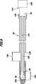
Gemäß einer weiteren bevorzugten Ausführungsform der Erfindung kann die Knochenschrauben eine Axialkopplungseinrichtung zum beweglichen Koppeln des distalen Schraubenteils und des proximalen Schraubenteils in einer Richtung parallel zur Längsachse umfassen. Insbesondere kann die Axialkopplungseinrichtung derart ausgebildet sein, dass die beiden Schraubenteile in einem begrenzten Umfang in axialer Richtung beweglich, jedoch nicht voneinander lösbar sind. Dies hat den Vorteil, dass die beiden Schraubenteile nur gemeinsam implantiert und auch wieder gemeinsam explantiert werden können.According to a further preferred embodiment of the invention, the bone screws may comprise an axial coupling device for movably coupling the distal screw part and the proximal screw part in a direction parallel to the longitudinal axis. In particular, the axial coupling device can be designed such that the two screw parts are movable to a limited extent in the axial direction, but not are detachable from each other. This has the advantage that the two screw parts can only be implanted together and also explanted together again.
Vorteilhaft ist es, wenn die Axialkopplungseinrichtung mindestens ein erstes und mindestens ein zweites Axialkopplungsglied umfasst, welche in einer Richtung parallel zur Längsachse formschlüssig oder im Wesentlichen formschlüssig miteinander in Eingriff stehen. So kann insbesondere eine definierte Führung einer axialen Bewegung der beiden Schraubenteile relativ zueinander sichergestellt werden. Querschnitte der Axialkopplungsglieder können insbesondere auch kreisförmig oder rund sein.It is advantageous if the axial coupling device comprises at least one first and at least one second axial coupling member, which are in a direction parallel to the longitudinal axis positively or substantially positively engaged with each other. Thus, in particular a defined guidance of an axial movement of the two screw parts can be ensured relative to each other. Cross-sections of the axial coupling members may in particular also be circular or round.
Günstig ist es, wenn das mindestens eine erste Axialkopplungsglied in Form eines parallel zur Längsachse abstehenden Axialkopplungsvorsprungs ausgebildet ist und wenn das mindestens eine zweite Axialkopplungsglied in Form einer zum Axialkopplungsvorsprung korrespondierend ausgebildeten Axialkopplungsaufnahme ausgebildet ist. Derart ausgebildete Axialkopplungsglieder ermöglichen insbesondere eine definiert geführte Bewegung der Schraubenteile relativ zueinander parallel zur Längsachse.It is expedient if the at least one first axial coupling element is designed in the form of an axial coupling projection projecting parallel to the longitudinal axis and if the at least one second axial coupling element is designed in the form of an axial coupling receptacle designed to correspond to the axial coupling projection. Such trained axial coupling in particular allow a defined guided movement of the screw parts relative to each other parallel to the longitudinal axis.
Besonders einfach wird der Aufbau der Knochenschraube, wenn das mindestens eine erste und/oder das mindestens eine zweite Axialkopplungsglied rotationssymmetrisch ausgebildet sind. Rotationssymmetrisch bedeutet insbesondere, dass Querschnitte der Axialkopplungsglieder kreisförmig oder rund sind, also nicht unbedingt unrund sein müssen.Particularly simple is the structure of the bone screw when the at least one first and / or the at least one second Axialkopplungsglied are rotationally symmetrical. In particular, rotational symmetry means that cross sections of the axial coupling elements are circular or round, that is, they do not necessarily have to be out of round.
Um den Aufbau der Knochenschraube so kompakt wie möglich zu gestalten, ist es vorteilhaft, wenn das mindestens eine erste Drehkopplungsglied und das mindestens eine zweite Drehkopplungsglied das mindestens eine erste und das mindestens eine zweite Axialkopplungsglied bilden. Die Drehkopplungsglieder können als insbesondere eine Doppelfunktion ausüben, nämlich zur Drehkopplung sowie zur axialen Kopplung der beiden Schraubenteile miteinander dienen.In order to make the construction of the bone screw as compact as possible, it is advantageous if the at least one first rotary coupling member and the at least one second rotary coupling member form the at least one first and the at least one second axial coupling member. The rotary coupling members can exert a particular dual function, namely for rotary coupling and for the axial coupling of the two screw parts serve each other.
Ferner kann es günstig sein, wenn die Knochenschraube eine Anschlageinrichtung zum Begrenzen eines Verschiebeweges des ersten und des zweiten Schraubenteils relativ zueinander umfasst. Die Knochenschraube kann somit insbesondere nur auf einer vom Verschiebeweg definierten Länge teleskopiert werden.Furthermore, it may be favorable if the bone screw comprises an abutment device for limiting a displacement path of the first and the second screw part relative to each other. The bone screw can thus be telescoped in particular only on a length defined by the displacement.
Günstigerweise liegt der Verschiebeweg in einem Bereich von etwa 3 mm bis etwa 30 mm.Conveniently, the displacement is in a range of about 3 mm to about 30 mm.
Vorteilhafterweise liegt der Verschiebeweg in einem Bereich von etwa 4 mm bis etwa 10 mm. Vorzugsweise beträgt er etwa 5 mm. Die angegebenen Bereiche für den Verschiebeweg decken somit insbesondere die besonderen Abmessungen ab, die für den Einsatz der Knochenschraube zur Behandlung einer Humeruskopffraktur vorteilhaft sind.Advantageously, the displacement path is in a range of about 4 mm to about 10 mm. It is preferably about 5 mm. The specified ranges for the displacement thus cover in particular the special dimensions which are advantageous for the use of the bone screw for the treatment of a humerus head fracture.
Die Knochenschraube lässt sich noch kompakter ausbilden, wenn die Axialkopplungseinrichtung die Anschlageinrichtung umfasst.The bone screw can be made even more compact if the axial coupling device comprises the stop device.
Ein Verschiebeweg der beiden Schraubenteile relativ zueinander kann auf einfache Weise dadurch begrenzt werden, wenn die Anschlageinrichtung mindestens einen ersten Anschlag zum Begrenzen einer Bewegung des ersten und des zweiten Schraubenteils aufeinander zu umfasst.A displacement of the two screw parts relative to each other can be limited in a simple manner, when the stop means comprises at least one first stop for limiting movement of the first and second screw member toward each other.
Um das unerwünschte und unabsichtliche Trennen der beiden Schraubenteile voneinander zu verhindern, ist es günstig, wenn die Anschlageinrichtung mindestens einen zweiten Anschlag zum Begrenzen einer Bewegung des ersten und des zweiten Schraubenteils voneinander weg umfasst.In order to prevent the unwanted and unintentional separation of the two screw parts from one another, it is favorable if the stop device comprises at least one second stop for limiting a movement of the first and the second screw part away from one another.
Ferner kann es vorteilhaft sein, wenn die Drehkopplungseinrichtung die Anschlageinrichtung umfasst. Dies ist insbesondere dann von Vorteil, wenn die Drehkopplungseinrichtung lediglich ein einziges Drehkopplungsglied umfasst, welches die beiden Schraubenteile drehfest miteinander koppelt und zugleich eine Bewegung derselben voneinander weg und/oder aufeinander zu in axialer Richtung begrenzt.Furthermore, it may be advantageous if the rotary coupling device comprises the stop device. This is particularly advantageous if the rotary coupling device comprises only a single rotary coupling member which rotatably coupled the two screw parts together and at the same time a movement thereof away from each other and / or limited to each other in the axial direction.
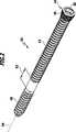
Eine besonders einfache Konstruktion der Knochenschraube ergibt sich, wenn das mindestens eine Drehkopplungsglied eine Schraubenfeder umfasst, welche mit dem distalen und mit dem proximalen Schraubenteil drehfest verbunden ist. Die Schraubenfeder dient damit als einziges Drehkopplungsglied zur Drehkopplung der beiden Schraubenteile relativ zueinander. Gleichzeitig kann sie jedoch auch einen Verschiebeweg der Schraubenteile aufeinander zu und/oder voneinander weg in gewünschter Weise begrenzen.A particularly simple construction of the bone screw results when the at least one rotary coupling member comprises a helical spring, which is connected in a rotationally fixed manner to the distal and to the proximal screw part. The helical spring thus serves as the only rotary coupling member for rotational coupling of the two screw parts relative to each other. At the same time, however, it can also limit a displacement path of the screw parts towards and / or away from one another in the desired manner.
Um die Funktion der Knochenschraube durch die Schraubenfeder möglichst wenig zu beeinträchtigen, ist es vorteilhaft, wenn die Schraubenfeder an einer Gewindeflanke des distalen Schraubenteils und an einer Gewindeflanke des proximalen Schraubenteils festgelegt ist.In order to minimize the effect on the function of the bone screw by the helical spring, it is advantageous if the helical spring is fixed to a thread flank of the distal screw part and to a thread flank of the proximal screw part.
Um eine Stabilität der Knochenschraube in gewünschter Weise sicherzustellen, ist es günstig, wenn die Schraubenfeder mit der Gewindeflanke des distalen Schraubenteils und/oder des proximalen Schraubenteils auf einer Länge fest verbunden ist, welche mindestens der doppelten Ganghöhe entspricht. Vorzugsweise entspricht die Länge, auf welcher die Schraubenfeder mit den Gewindeflächen der Schraubenteile verbunden ist, mindestens der vierfachen Ganghöhe. Die Ganghöhe in diesem Sinn ist definiert als der Abstand zweier Gewindeflanken in axialer Richtung. Damit bedeutet eine Festlegung auf mindestens der doppelten Ganghöhe, dass die Schraubenfeder längs zweier, sich über jeweils 360° erstreckende Schrauben am Schraubenteil befestigt ist. Eine Befestigung kann insbesondere durch Löten, Schweißen und/oder Kleben erfolgen.In order to ensure a stability of the bone screw in the desired manner, it is favorable if the helical spring is firmly connected to the thread flank of the distal screw part and / or the proximal screw part over a length which corresponds at least to twice the pitch. Preferably, the length corresponds to which the coil spring is connected to the threaded surfaces of the screw parts, at least four times the pitch. The pitch in this sense is defined as the distance between two thread flanks in the axial direction. Thus, a commitment to at least twice the pitch means that the coil spring along two, extending over each 360 ° screws is attached to the screw part. An attachment can be made in particular by soldering, welding and / or gluing.
Gemäß einer weiteren bevorzugten Ausführungsform der Erfindung kann vorgesehen sein, dass die Knochenschraube eine Abstandshalteeinrichtung zum Halten des proximalen Schraubenteils und des distalen Schraubenteils in einer bezogen auf eine in axialer Richtung maximal angenäherte Stellung ausgelenkten Stellung. Mit anderen Worten begrenzt die Abstandshalteeinrichtung einen Weg der Schraubenteile aufeinander zu. Insbesondere kann die Abstandshalteeinrichtung in Form einer dynamischen Abstandshalteeinrichtung ausgebildet sein, welche mit zunehmender Verringerung eines Abstands oder einer Bewegung der Schraubenteile aufeinander zu zunehmende Kräfte erfordert, um einen Abstand weiter zu verringern. Sie kann also insbesondere auch in Form einer Rückstelleinrichtung ausgebildet sein, die bestrebt ist, die beiden Schraubenteile wieder so relativ zueinander zu positionieren, dass sie möglichst einen in einer Grundstellung definierten Abstand voneinander einnehmen. Werden die Schraubenteile beispielsweise relativ zueinander aus der Grundstellung ausgelenkt, also weiter voneinander entfernt oder weiter aufeinander zu als in der Grundstellung bewegt, kann die Rückstelleinrichtung die Schraubenteile wieder automatisch zurück in die Grundstellung bewegen.According to a further preferred embodiment of the invention, it may be provided that the bone screw has a spacer device for holding the proximal screw part and the distal screw part in a position which is deflected in relation to a position which is maximally approximated in the axial direction. In other words, the spacer device limits a path of the screw parts toward one another. In particular, the spacer means may be in the form of a dynamic spacer means which, with increasing reduction of a distance or movement of the screw members towards each other, requires increasing forces to further reduce a distance. It can thus be designed, in particular, in the form of a restoring device, which endeavors to position the two screw parts relative to one another in such a way that they occupy as far as possible a distance defined in a basic position from one another. For example, if the screw parts are deflected relative to one another out of the basic position, ie further away from one another or further toward one another than in the basic position, the restoring device can automatically move the screw parts back into the basic position.
Günstig ist es, wenn die ausgelenkte Stellung eine maximal ausgelenkte Stellung definiert, in welcher der distale Schraubenteil maximal weit weg vom proximalen Schraubenteil in distaler Richtung bewegt ist. Auf diese Weise kann sichergestellt werden, dass die beiden Schraubenteile immer einen gewissen Mindestabstand voneinander aufweisen beziehungsweise eine Länge zwischen dem distalen Ende des distalen Schraubenteils und dem proximalen Ende des proximalen Schraubenteils maximal ist.It is favorable if the deflected position defines a maximally deflected position in which the distal screw part is moved at a maximum distance far away from the proximal screw part in the distal direction. In this way it can be ensured that the two screw parts always have a certain minimum distance from one another or a length between the distal end of the distal screw part and the proximal end of the proximal screw part is maximum.
Auf besonders einfache Weise lässt sich die Abstandshalteeinrichtung ausbilden, wenn sie mindestens ein Abstandshalteelement umfasst zum Halten des proximalen Schraubenteils und des distalen Schraubenteils in einer bezogen auf eine in axialer Richtung maximal angenäherte Stellung ausgelenkten Stellung. So kann beispielsweise schon durch ein einziges Abstandshalteelement sichergestellt werden, dass die beiden Schraubenteile die gewünschte axiale Position relativ zueinander einnehmen.The spacer device can be formed in a particularly simple manner if it comprises at least one spacer element for holding the proximal screw part and the distal screw part in a position deflected relative to a position which is maximally approximated in the axial direction. For example, it can be ensured by a single spacer element that the two screw parts assume the desired axial position relative to each other.
Gemäß einer weiteren bevorzugten Ausführungsform der Erfindung kann vorgesehen sein, dass das mindestens eine Abstandshalteelement eine in distaler Richtung weisende distale Abstandshalteelementanschlagfläche und eine in proximaler Richtung weisende proximale Abstandshalteelementanschlagfläche umfasst und dass in der ausgelenkten Stellung die distale Abstandshalteelementanschlagfläche mit einer in proximaler Richtung weisenden proximalen Schraubenteilanschlagfläche des distalen Schraubenteils und die proximale Abstandshalteelementanschlagfläche mit einer in distaler Richtung weisenden distalen Schraubenteilanschlagfläche des proximalen Schraubenteils zusammenwirken. Die genannten Flächen ermöglichen es insbesondere, sicherzustellen, dass die Schraubenteile nur so weit aufeinander zu bewegt werden können, dass die Knochenschraube insgesamt eine minimale Länge nicht unterschreitet.According to a further preferred embodiment of the invention, it can be provided that the at least one spacer element comprises a distally pointing distal spacer stop surface and a proximally facing proximal spacer stop surface and in the deflected position the distal spacer stop surface with a proximally facing proximal screw stop surface distal screw member and the proximal spacer stop surface cooperate with a distally facing distal screw abutment surface of the proximal screw member. In particular, the surfaces mentioned make it possible to ensure that the screw parts can only be moved toward one another to such an extent that the bone screw as a whole does not fall below a minimum length.
Günstigerweise ist das mindestens eine Abstandshalteelement in Form eines elastischen Elements ausgebildet. Ein solches Abstandshalteelement kann insbesondere auch eine Bewegung der Schraubenteile aufeinander zu und gegebenenfalls voneinander weg dämpfen. Das Abstandshalteelement kann also quasi wie in Puffer wirken, welcher auf Druck und/oder Zug belastbar sein kann.Conveniently, the at least one spacer element is designed in the form of an elastic element. In particular, such a spacer element can also damp a movement of the screw parts toward one another and optionally away from one another. The spacer element can thus act as if in buffer, which can be loaded on pressure and / or train.
Auf besonders einfache Weise lässt das elastische Element in Form einer Feder ausbilden. Es kann sich dabei um eine Druck- und/oder um eine Zugfeder handeln.In a particularly simple manner, the elastic element can form in the form of a spring. It may be a pressure and / or a tension spring.
Ferner kann es vorteilhaft sein, wenn das mindestens eine Abstandshalteelement aus einem resorbierbaren Material hergestellt ist. Als resorbierbare biokompatible Materialien kommen insbesondere Gelatine oder Polylactid in Frage. Das Abstandshalteelement kann so nach der Implantation der Knochenschraube vom Körper resorbiert werden, um eine Bewegung der Schraubenteile noch weiter aufeinander zu zu ermöglichen, als dies bei der Implantation und Vorhandensein des Abstandshalteelements möglich ist.Furthermore, it may be advantageous if the at least one spacer element is made of a resorbable material. Suitable resorbable biocompatible materials are, in particular, gelatin or polylactide. The spacer element can thus be resorbed by the body after implantation of the bone screw in order to allow movement of the screw parts even further towards one another than is possible during the implantation and presence of the spacer element.
Besonders kompakt ausbilden lässt sich die Knochenschraube, wenn das mindestens eine Abstandshalteelement in der Drehkopplungsaufnahme und/oder in der Axialkopplungsaufnahme angeordnet ist. So kann es sich insbesondere an einem distalen Ende des proximalen Schraubenteils oder alternativ an einem proximalen Ende des distalen Schraubenteils abstützen, um eine Bewegung der Schraubenteile aufeinander zu zu begrenzen.The bone screw can be made particularly compact if the at least one spacer element is arranged in the rotary coupling receptacle and / or in the axial coupling receptacle. Thus, it may in particular be supported on a distal end of the proximal screw part or alternatively on a proximal end of the distal screw part, in order to limit movement of the screw parts towards one another.
Günstigerweise ist das mindestens eine Abstandshalteelement in Form eines Abstandshaltekörpers ausgebildet. Dieser kann wahlweise elastisch oder inelastisch sein. Er kann optional resorbierbar oder nicht resorbierbar ausgebildet sein. Ferner kann er auch aus zwei oder mehr unterschiedlichen Materialien hergestellt sein.Conveniently, the at least one spacer element is designed in the form of a spacer body. This can optionally be elastic or inelastic. He can optionally absorbable or be formed non-absorbable. Further, it may also be made of two or more different materials.
Gemäß einer weiteren bevorzugten Ausführungsform der Erfindung kann vorgesehen sein, dass das mindestens eine Drehkopplungsglied das mindestens eine Abstandshalteelement bildet oder umfasst. Insbesondere wenn nur ein einziges Drehkopplungsglied vorgesehen ist, beispielsweise in Form einer Schraubenfeder, kann diese gleichzeitig das Abstandshalteelement bilden, also eine Bewegung der beiden Schraubenteile aufeinander zu begrenzen.According to a further preferred embodiment of the invention, it can be provided that the at least one rotary coupling member forms or comprises the at least one spacer element. In particular, if only a single rotary coupling member is provided, for example in the form of a helical spring, this can simultaneously form the spacer element, ie to limit a movement of the two screw parts to each other.
Vorteilhaft ist es, wenn das mindestens eine Abstandshalteelement den mindestens einen Drehkopplungsvorsprung und/oder den mindestens einen Axialkopplungsvorsprung mindestens abschnittsweise umgibt. Insbesondere bei resorbierbaren Abstandshalteelementen hat dies den Vorteil, dass eine Resorption beschleunigt erfolgen kann. Außerdem ist so für einen Operateur sofort erkennbar, welchen Abstand das Abstandshalteelement gegebenenfalls definiert, insbesondere temporär.It is advantageous if the at least one spacer element at least partially surrounds the at least one rotary coupling projection and / or the at least one axial coupling projection. In particular, in the case of resorbable spacer elements, this has the advantage that absorption can be accelerated. In addition, it is immediately apparent to a surgeon which distance the spacer element optionally defines, in particular temporarily.
Besonders einfach herzustellen ist das mindestens eine Abstandshalteelement, wenn es in Form einer Hülse ausgebildet ist. Wahlweise kann es, wie bereits beschrieben, auch in Form einer Feder ausgebildet sein, beispielsweise in Form einer Schraubenfeder.Particularly easy to manufacture is the at least one spacer element when it is in the form of a sleeve. Optionally, it may, as already described, also be in the form of a spring, for example in the form of a helical spring.
Um ein synchrones Einschrauben beider Schraubenteile in Knochenfragmente zu ermöglichen, ist es günstig, wenn eine Steigung des distalen Knochengewindes einer Steigung des proximalen Knochengewindes entspricht oder im Wesentlichen entspricht.In order to enable a synchronous screwing in of both screw parts in bone fragments, it is favorable if a pitch of the distal bone thread corresponds or substantially corresponds to a pitch of the proximal bone thread.
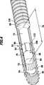
Die Handhabung der Knochenschraube lässt sich weiter verbessern, wenn der proximale Schraubenteil eine Werkzeugelementaufnahme zum kraft- und/oder formschlüssigen in Eingriff Bringen mit einem Werkzeugelement eines Einschraubwerkzeugs umfasst. Die Werkzeugelementaufnahme kann in Form eines Vorsprungs oder einer Aufnahme ausgebildet sein, insbesondere sind Querschnitte derselben denkbar, die von einer Kreisform oder einer runden Form abweichend sind, also insbesondere vieleckige oder vielrunde Querschnitte oder alternativ ovale Querschnitte.The handling of the bone screw can be further improved if the proximal screw part comprises a tool element receptacle for frictional and / or positive engagement with a tool element of a screw-in tool. The tool element receptacle can be designed in the form of a projection or a receptacle, in particular, cross sections of the same are conceivable, which deviate from a circular or round shape, ie in particular polygonal or multi-circular cross sections or alternatively oval cross sections.
Auf einfache Weise zugänglich wird die Werkzeugelementaufnahme, wenn sie in proximaler Richtung weisend geöffnet ist.The tool element receptacle becomes accessible in a simple manner when it is open in the proximal direction.
Ferner kann es günstig sein, wenn der proximale Schraubenteil einen sich parallel zur Längsachse verlaufenden Kanal umfasst, welcher sich von einem proximalen bis zu einem distalen Ende des proximalen Schraubenteils erstreckt. Ein solcher Kanal gestattet es, ein Einschraubwerkzeug zu verwenden, welches ein durch den Kanal hindurchführbares Abstandshalteelement umfasst, um beim Einschrauben der Knochenschraube eine minimale Länge derselben vorzugeben. Vorzugsweise ist das Abstandshalteelement so bemessen, dass es über ein distales Ende des proximalen Schaftteils vorsteht, wenn das Einschraubwerkzeug mit dem proximalen Schraubenteil in Eingriff steht.Furthermore, it may be favorable if the proximal screw part comprises a channel extending parallel to the longitudinal axis, which extends from a proximal to a distal end of the proximal screw part. Such a channel makes it possible to use a screw-in tool which comprises a spacer element which can be passed through the channel in order to predetermine a minimum length thereof when the bone screw is screwed in. Preferably, the spacer member is sized to project beyond a distal end of the proximal shaft portion when the screw-in tool engages the proximal screw portion.
Die eingangs gestellte Aufgabe wird ferner bei einem Knochenfixierungssystem der eingangs beschriebenen Art erfindungsgemäß dadurch gelöst, dass die Knochenschraube eine Drehkopplungseinrichtung zum drehfesten Koppeln des distalen Schraubenteils und des proximalen Schraubenteils in Umfangsrichtung umfasst.The object stated in the introduction is also achieved according to the invention in a bone fixation system of the type described above in that the bone screw comprises a rotational coupling device for rotationally fixed coupling of the distal screw part and the proximal screw part in the circumferential direction.
Wie bereits oben eingehend dargelegt, ist es so nicht mehr erforderlich, den proximalen Schraubenteil zu kanülieren, um den distalen Schraubenteil der Knochenschraube in den Knochen einschrauben zu können.As explained in detail above, it is no longer necessary to cannulate the proximal screw part in order to screw the distal screw part of the bone screw into the bone can.
Vorteilhaft ist es ferner, wenn das Knochenfixierungssystem eine der oben beschriebenen Knochenschrauben umfasst. Das Knochenfixierungssystem weist dann die oben im Zusammenhang mit bevorzugten Ausführungsformen von Knochenschrauben beschriebenen Vorteile auf.It is also advantageous if the bone fixation system comprises one of the bone screws described above. The bone fixation system then has the advantages described above in connection with preferred embodiments of bone screws.
Günstig ist es ferner, wenn das Knochenfixierungssystem ein Einschraubwerkzeug umfasst, welches ein mit einer Werkzeugelementaufnahme des proximalen Schraubenteils in Eingriff bringbares Werkzeugelement umfasst zum Einschrauben der Knochenschraube in die mindestens zwei Knochenteile. Mit dem Einschraubwerkzeug kann der proximale Schraubenteil rotiert werden, welcher über die Drehkopplungseinrichtung mit dem distalen Schraubenteil drehfest gekoppelt ist.It is also expedient if the bone fixation system comprises a screw-in tool which comprises a tool element which can be brought into engagement with a tool element receptacle of the proximal screw part for screwing the bone screw into the at least two bone parts. With the Einschraubwerkzeug the proximal screw part can be rotated, which is rotatably coupled via the rotary coupling device with the distal screw part.
Gemäß einer weiteren bevorzugten Ausführungsform der Erfindung kann vorgesehen sein, dass der proximale Schraubenteil einen sich parallel zur Längsachse verlaufenden Kanal umfasst, welcher sich von einem proximalen bis zu einem distalen Ende des proximalen Schraubenteils erstreckt, und dass das Einschraubwerkzeug ein in den Kanal einführbares Abstandshalteelement umfasst, welches distalseitig über ein distales Ende des proximalen Schraubenteils vorsteht, wenn das Werkzeugelement und die Werkzeugelementaufnahme in Eingriff stehen. Mit einem solchen Einschraubwerkzeug kann somit auf einfache Weise eine Bewegung der beiden Schraubenteile aufeinander zu begrenzt werden. Insbesondere kann die Knochenschraube so ausgebildet sein, dass nach Entfernen des Einschraubwerkzeugs eine Bewegung der Schraubenteile noch weiter aufeinander zu möglich ist, als dies beim Einschrauben mit dem Einschraubwerkzeug möglich ist.According to a further preferred embodiment of the invention, it may be provided that the proximal screw part comprises a channel extending parallel to the longitudinal axis, which extends from a proximal to a distal end of the proximal screw part, and in that the screwing-in tool comprises a spacer element insertable into the channel which projects distally beyond a distal end of the proximal screw member when the tool member and the tool member receptacle are engaged. With such a screw-in tool, a movement of the two screw parts can thus be limited to one another in a simple manner. In particular, the bone screw may be designed so that after removal of the screwing a movement of the screw parts still continue to each other is possible, as is possible when screwing with the screwing.
Die vorstehende Beschreibung umfasst somit insbesondere die nachfolgend explizit aufgeführten Ausführungsformen einer Knochenschraube und eines Knochenfixierungssystems:
- 1. Knochenschraube (
20 ;160 ) mit einem distalen Schraubenteil (34 ;162 ) und einem proximalen Schraubenteil (36 ;176 ), welcher distale Schraubenteil (34 ;162 ) ein distales Knochengewinde (40 ;164 ) umfasst und welcher proximale Schraubenteil (36 ;176 ) ein proximales Knochengewinde (42 ;182 ) umfasst, wobei der distale Schraubenteil (34 ;162 ) und der proximale Schraubenteil (36 ;176 ) relativ zueinander in einer Richtung parallel zu einer von der Knochenschraube (20 ;160 ) definierten Längsachse (54 ;192 ) verschiebbar sind, gekennzeichnet durch eine Drehkopplungseinrichtung (82 ;194 ) zum drehfesten Koppeln des distalen Schraubenteils (34 ;162 ) und des proximalen Schraubenteils (36 ;176 ) in Umfangsrichtung. - 2. Knochenschraube nach Satz 1, dadurch gekennzeichnet, dass die Drehkopplungseinrichtung (
82 ;194 ) mindestens ein Drehkopplungsglied (84 ,86 ;196 ) umfasst, welches den distalen Schraubenteil (34 ;162 ) und den proximalen Schraubenteil (36 ;176 ) miteinander drehfest koppelt. - 3. Knochenschraube nach Satz 2, dadurch gekennzeichnet, dass die Drehkopplungseinrichtung (
82 ) mindestens zwei miteinander zusammenwirkende erste und zweite Drehkopplungsglieder (84 ,86 ) umfasst, welche miteinander drehfest in Eingriff stehen. - 4. Knochenschraube nach Satz 3, dadurch gekennzeichnet, dass das mindestens eine erste und das mindestens eine zweite Drehkopplungsglied (
84 ,86 ) in einer Richtung parallel zur Längsachse (54 ) formschlüssig oder im Wesentlichen formschlüssig ineinander einführbar sind. - 5. Knochenschraube nach Satz 3 oder 4, dadurch gekennzeichnet, dass das mindestens eine erste Drehkopplungsglied (
84 ) in Form eines parallel zur Längsachse (54 ) abstehenden Drehkopplungsvorsprungs (88 ) ausgebildet ist und dass das mindestens eine zweite Drehkopplungsglied (86 ) in Form einer zum Drehkopplungsvorsprung (88 ) korrespondierend ausgebildeten Drehkopplungsaufnahme ausgebildet ist. - 6. Knochenschraube nach einem der Sätze 3 bis 5, dadurch gekennzeichnet, dass das mindestens eine erste Drehkopplungsglied (
88 ) an einem distalen Ende (66 ) oder im Bereich des distalen Endes (66 ) des proximalen Schraubenteils (36 ) angeordnet oder ausgebildet ist und dass das mindestens eine zweite Drehkopplungsglied (86 ) an einem proximalen Ende (62 ) oder im Bereich des proximalen Endes (62 ) des distalen Schraubenteils (34 ) angeordnet oder ausgebildet ist. - 7. Knochenschraube nach einem der Sätze 3 bis 6, dadurch gekennzeichnet, dass das mindestens eine erste und das mindestens eine zweite Drehkopplungsglied (
88 ,90 ) einen von einer Rotationssymmetrie abweichenden Querschnitt aufweisen. - 8. Knochenschraube nach einem der Sätze 3 bis 7, dadurch gekennzeichnet, dass Querschnitte des mindestens einen ersten und des mindestens einen zweiten Drehkopplungsglieds (
84 ,86 ) unrund sind. - 9. Knochenschraube nach Satz 7 oder 8, dadurch gekennzeichnet, dass die Querschnitte oval oder vieleckig sind, insbesondere sechseckig.
- 10. Knochenschraube nach einem der voranstehenden Sätze, gekennzeichnet durch eine Axialkopplungseinrichtung (
52 ;170 ) zum beweglichen Koppeln des distalen Schraubenteils (34 ;162 ) und des proximalen Schraubenteils (36 ;176 ) in einer Richtung parallel zur Längsachse (54 ;192 ). - 11.
Knochenschraube nach Satz 10, dadurch gekennzeichnet, dass die Axialkopplungseinrichtung (52 ;170 ) mindestens ein erstes und mindestens ein zweites Axialkopplungsglied (56 ,58 ;172 ,188 ) umfasst, welche in einer Richtung parallel zur Längsachse (54 ;192 ) formschlüssig oder im Wesentlichen formschlüssig miteinander in Eingriff stehen. - 12. Knochenschraube nach Satz 11, dadurch gekennzeichnet, dass das mindestens eine erste Axialkopplungsglied (
56 ;172 ) in Form eines parallel zur Längsachse (54 ;192 ) abstehenden Axialkopplungsvorsprungs (70 ;170 ) ausgebildet ist und dass das mindestens eine zweite Axialkopplungsglied (58 ;188 ) in Form einer zum Axialkopplungsvorsprung (70 ;170 ) korrespondierend ausgebildeten Axialkopplungsaufnahme (72 ;190 ) ausgebildet ist. - 13. Knochenschraube nach Satz 11 oder 12, dadurch gekennzeichnet, dass das mindestens eine erste und/oder das mindestens eine zweite Axialkopplungsglied (
170 ,190 ) rotationssymmetrisch ausgebildet sind. - 14. Knochenschraube nach einem der Sätze 11 bis 13, dadurch gekennzeichnet, dass das mindestens eine erste Drehkopplungsglied (
88 ) und das mindestens eine zweite Drehkopplungsglied (90 ) das mindestens eine erste und das mindestens eine zweite Axialkopplungsglied (56 ,58 ) bilden. - 15. Knochenschraube nach einem der voranstehenden Sätze, gekennzeichnet durch eine Anschlageinrichtung (
92 ;208 ) zum Begrenzen eines Verschiebeweges (93 ) des ersten und des zweiten Schraubenteils (34 ,36 ;162 ,176 ) relativ zueinander. - 16. Knochenschraube nach Satz 15, gekennzeichnet durch einen Verschiebeweg (
93 ) in einem Bereich von etwa 3 mm bis etwa 30 mm. - 17.
Knochenschraube nach Satz 16, gekennzeichnet durch einen Verschiebeweg (93 ) in einem Bereich von etwa 4 mm bis etwa 10 mm. - 18. Knochenschraube nach einem der Sätze 15 bis 17, dadurch gekennzeichnet, dass die Axialkopplungseinrichtung (
70 ;170 ) die Anschlageinrichtung (92 ;208 ) umfasst. - 19. Knochenschraube nach einem der Sätze 15
bis 18, dadurch gekennzeichnet, dass die Anschlageinrichtung (92 ;208 ) mindestens einen ersten Anschlag (94 ;210 ) zum Begrenzen einer Bewegung des ersten und des zweiten Schraubenteils (34 ,36 ;162 ,176 ) aufeinander zu umfasst. - 20. Knochenschraube nach einem der Sätze 15 bis 19, dadurch gekennzeichnet, dass die Anschlageinrichtung (
92 ) mindestens einen zweiten Anschlag (98 ) zum Begrenzen einer Bewegung des ersten und des zweiten Schraubenteils (34 ,36 ) voneinander weg umfasst. - 21. Knochenschraube nach einem der Sätze 15
bis 20, dadurch gekennzeichnet, dass die Drehkopplungseinrichtung (82 ) die Anschlageinrichtung (92 ) umfasst. - 22. Knochenschraube nach Satz 21, dadurch gekennzeichnet, dass das mindestens eine Drehkopplungsglied (
196 ) eine Schraubenfeder (198 ) umfasst, welche mit dem distalen und mit dem proximalen Schraubenteil (162 ,176 ) drehfest verbunden ist. - 23. Knochenschraube nach Satz 23, dadurch gekennzeichnet, dass die Schraubenfeder (
196 ) an einer Gewindeflanke (204 ) des distalen Schraubenteils (162 ) und an einer Gewindeflanke (206 ) des proximalen Schraubenteils (176 ) festgelegt ist. - 24. Knochenschraube nach Satz 23, dadurch gekennzeichnet, dass die Schraubenfeder (
198 ) mit der Gewindeflanke (204 ,206 ) des distalen Schraubenteils (162 ) und/oder des proximalen Schraubenteils (176 ) auf einer Länge fest verbunden ist, welche mindestens der doppelten Ganghöhe, vorzugsweise der mindestens vierfachen Ganghöhe entspricht. - 25. Knochenschraube nach einem der voranstehenden Sätze, gekennzeichnet durch eine Abstandshalteeinrichtung (
38 ;38' ;216 ) zum Halten des proximalen Schraubenteils (36 ;176 ) und des distalen Schraubenteils (34 ;162 ) in einer bezogen auf eine in axialer Richtung maximal angenäherte Stellung ausgelenkten Stellung. - 26. Knochenschraube nach Satz 25, dadurch gekennzeichnet, dass die ausgelenkte Stellung eine maximal ausgelenkte Stellung definiert, in welcher der distale Schraubenteil (
34 ;162 ) maximal weit weg vom proximalen Schraubenteil (36 ;176 ) in distaler Richtung bewegt ist. - 27. Knochenschraube nach Satz 25 oder 26, dadurch gekennzeichnet, dass die Abstandshalteeinrichtung (
38 ;38' ;216 ) mindestens ein Abstandshalteelement (108 ;108' ;218 ) umfasst zum Halten des proximalen Schraubenteils (36 ;176 ) und des distalen Schraubenteils (34 ;162 ) in einer bezogen auf eine in axialer Richtung maximal angenäherte Stellung ausgelenkten Stellung. - 28. Knochenschraube nach Satz 27, dadurch gekennzeichnet, dass das mindestens eine Abstandshalteelement (
108 ) eine in distaler Richtung weisende distale Abstandshalteelementanschlagfläche (114 ) und eine in proximaler Richtung weisende proximale Abstandshalteelementanschlagfläche (116 ) umfasst und dass in der ausgelenkten Stellung die distale Abstandshalteelementanschlagfläche (114 ) mit einer in proximaler Richtung weisenden proximalen Schraubenteilanschlagfläche (124 ) des distalen Schraubenteils (34 ) und die proximale Abstandshalteelementanschlagfläche mit einer in distaler Richtung weisenden distalen Schraubenteilanschlagfläche (126 ) des proximalen Schraubenteils (36 ) zusammenwirken. - 29. Knochenschraube nach Satz 27 oder 28, dadurch gekennzeichnet, dass das mindestens eine Abstandshalteelement (
108 ;108' ;218 ) in Form eines elastischen Elements (130 ) ausgebildet ist. - 30. Knochenschraube nach Satz 29, dadurch gekennzeichnet, dass das elastische Element (
130 ) in Form einer Feder (128 ;198 ) ausgebildet ist. - 31. Knochenschraube nach Satz 29 oder 30, dadurch gekennzeichnet, dass das mindestens eine Abstandshalteelement (
108 ) aus einem resorbierbaren Material hergestellt ist, insbesondere aus Gelatine. - 32. Knochenschraube nach einem der Sätze 27 bis 31, dadurch gekennzeichnet, dass das mindestens eine Abstandshalteelement (
108' ) in der Drehkopplungsaufnahme (90 ) und/oder in der Axialkopplungsaufnahme (72 ) angeordnet ist. - 33.
Knochenschraube nach Satz 32, dadurch gekennzeichnet, dass das mindestens eine Abstandshalteelement (108 ) in Form eines Abstandshaltekörpers (110 ) ausgebildet ist. - 34. Knochenschraube nach einem der Sätze 27 bis 33 soweit sie direkt oder indirekt auf einen der Sätze 22 bis 24 rückbezogen sind, dadurch gekennzeichnet, dass das mindestens eine Drehkopplungsglied (
196 ) das mindestens eine Abstandshalteelement (218 ) bildet oder umfasst. - 35. Knochenschraube nach einem der Sätze 27
bis 34, dadurch gekennzeichnet, dass das mindestens eine Abstandshalteelement (108 ;218 ) den mindestens einen Drehkopplungsvorsprung (88 ) und/oder den mindestens einen Axialkopplungsvorsprung (70 ) mindestens abschnittsweise umgibt. - 36. Knochenschraube nach Satz 35, dadurch gekennzeichnet, dass das mindestens eine Abstandshalteelement (
108 ) in Form einer Hülse (112 ) ausgebildet ist. - 37. Knochenschraube nach einem der voranstehenden Sätze, dadurch gekennzeichnet, dass das eine Steigung des distalen Knochengewindes (
40 ) einer Steigung des proximalen Knochengewindes (42 ) entspricht. - 38. Knochenschraube nach einem der voranstehenden Sätze, dadurch gekennzeichnet, dass der proximale Schraubenteil (
36 ) eine Werkzeugelementaufnahme (50 ) zum kraft- und/oder formschlüssigen in Eingriff Bringen mit einem Werkzeugelement eines Einschraubwerkzeugs umfasst. - 39.
Knochenschraube nach Satz 38, dadurch gekennzeichnet, dass die Werkzeugelementaufnahme (50 ) in proximaler Richtung weisend geöffnet ist. - 40. Knochenschraube nach einem der voranstehenden Sätze, dadurch gekennzeichnet, dass der proximale Schraubenteil (
36 ) einen sich parallel zur Längsachse (54 ) verlaufenden Kanal (142 ) umfasst, welcher sich von einem proximalen bis zu einem distalen Ende des proximalen Schraubenteils (36 ) erstreckt. - 41. Knochenfixierungssystem (
10 ) zum Verbinden von mindestens zwei voneinander in Folge einer Fraktur getrennten Knochenteilen (12 ), umfassend mindestens eine mindestens eine Durchbrechung (16 ) aufweisende Knochenplatte (14 ) und mindestens eine durch die Durchbrechung (16 ) mindestens teilweise durchführbare Knochenschraube (20 ;160 ), welche Knochenschraube (20 ;160 ) einen distalen Schraubenteil (34 ;162 ) und einen proximalen Schraubenteil (36 ;176 ) umfasst, welcher distale Schraubenteil (34 ;162 ) ein distales Knochengewinde (40 ;164 ) umfasst und welcher proximale Schraubenteil (36 ;176 ) ein proximales Knochengewinde (42 ;182 ) umfasst, wobei der distale Schraubenteil (34 ;162 ) und der proximale Schraubenteil (36 ;176 ) relativ zueinander in einer Richtung parallel zu einer von der Knochenschraube (20 ;160 ) definierten Längsachse (54 ;192 ) verschiebbar sind, gekennzeichnet durch eine Drehkopplungseinrichtung (82 ;194 ) zum drehfesten Koppeln des distalen Schraubenteils (34 ;162 ) und des proximalen Schraubenteils (36 ;176 ) in Umfangsrichtung. - 42. Knochenfixierungssystem nach Satz 41, gekennzeichnet durch eine Knochenschraube (
20 ;160 ) nach einem der Sätze 2bis 40. - 43. Knochenfixierungssystem nach Satz 41 oder 42, gekennzeichnet durch ein Einschraubwerkzeug (
144 ), welches ein mit einer Werkzeugelementaufnahme (50 ) des proximalen Schraubenteils (36 ) in Eingriff bringbares Werkzeugelement (146 ) umfasst zum Einschrauben der Knochenschraube (20 ) in die mindestens zwei Knochenteile (12 ). - 44. Knochenfixierungssystem nach Satz 43, dadurch gekennzeichnet, dass der proximale Schraubenteil (
36 ) einen sich parallel zur Längsachse (54 ) verlaufenden Kanal (142 ) umfasst, welcher sich von einem proximalen bis zu einem distalen Ende des proximalen Schraubenteils (36 ) erstreckt, und dass das Einschraubwerkzeug (144 ) ein in den Kanal (142 ) einführbares Abstandshalteelement (150 ) umfasst, welches distalseitig über ein distales Ende des proximalen Schraubenteils (36 ) vorsteht, wenn das Werkzeugelement (146 ) und die Werkzeugelementaufnahme (50 ) in Eingriff stehen.
- 1. Bone screw (
20 ;160 ) with a distal screw part (34 ;162 ) and a proximal screw part (36 ;176 ), which distal screw part (34 ;162 ) a distal bone thread (40 ;164 ) and which proximal screw part (36 ;176 ) a proximal bone thread (42 ;182 ), wherein the distal screw part (34 ;162 ) and the proximal screw part (36 ;176 ) relative to one another in a direction parallel to one of the bone screw (20 ;160 ) defined longitudinal axis (54 ;192 ) are displaceable, characterized by a rotary coupling device (82 ;194 ) for the rotationally fixed coupling of the distal screw part (34 ;162 ) and the proximal screw part (36 ;176 ) in the circumferential direction. - 2. Bone screw according to sentence 1, characterized in that the rotary coupling device (
82 ;194 ) at least one rotary coupling member (84 .86 ;196 ) comprising the distal screw part (34 ;162 ) and the proximal screw part (36 ;176 ) rotatably coupled with each other. - 3. Bone screw according to sentence 2, characterized in that the rotary coupling device (
82 ) at least two mutually cooperating first and second rotary coupling members (84 .86 ), which are rotatably engaged with each other. - 4. bone screw according to sentence 3, characterized in that the at least one first and the at least one second rotary coupling member (
84 .86 ) in a direction parallel to the longitudinal axis (54 ) are inserted into each other in a form-fitting or substantially positive fit. - 5. Bone screw according to sentence 3 or 4, characterized in that the at least one first rotary coupling member (
84 ) in the form of a parallel to the longitudinal axis (54 ) protruding rotary coupling projection (88 ) is formed and that the at least one second rotary coupling member (86 ) in the form of a rotary coupling projection (88 ) formed corresponding rotary coupling receptacle is formed. - 6. Bone screw according to one of the sentences 3 to 5, characterized in that the at least one first rotary coupling member (
88 ) at a distal end (66 ) or in the area of the distal end (66 ) of the proximal screw part (36 ) is arranged or formed and that the at least one second rotary coupling member (86 ) at a proximal end (62 ) or near the proximal end (62 ) of the distal screw part (34 ) is arranged or formed. - 7. Bone screw according to one of the sentences 3 to 6, characterized in that the at least one first and the at least one second rotary coupling member (
88 .90 ) have a different from a rotational symmetry cross-section. - 8. Bone screw according to one of the sentences 3 to 7, characterized in that cross sections of the at least one first and the at least one second rotary coupling member (
84 .86 ) are out of round. - 9. bone screw according to sentence 7 or 8, characterized in that the cross-sections are oval or polygonal, in particular hexagonal.
- 10. Bone screw according to one of the preceding sentences, characterized by an axial coupling device (
52 ;170 ) for movably coupling the distal screw part (34 ;162 ) and the proximal screw part (36 ;176 ) in a direction parallel to the longitudinal axis (54 ;192 ). - 11. Bone screw according to
sentence 10, characterized in that the axial coupling device (52 ;170 ) at least a first and at least one second Axialkopplungsglied (56 .58 ;172 .188 ), which in a direction parallel to the longitudinal axis (54 ;192 ) are positively or substantially positively engaged with each other. - 12. Bone screw according to sentence 11, characterized in that the at least one first Axialkopplungsglied (
56 ;172 ) in the form of a parallel to the longitudinal axis (54 ;192 ) projecting Axialkopplungsvorsprungs (70 ;170 ) is formed and that the at least one second Axialkopplungsglied (58 ;188 ) in the form of a to the Axialkopplungsvorsprung (70 ;170 ) correspondingly formed Axialkopplungsaufnahme (72 ;190 ) is trained. - 13. Bone screw according to
sentence 11 or 12, characterized in that the at least one first and / or the at least one second Axialkopplungsglied (170 .190 ) are rotationally symmetrical. - 14. Bone screw according to one of the sentences 11 to 13, characterized in that the at least one first rotary coupling member (
88 ) and the at least one second rotary coupling member (90 ) the at least one first and the at least one second axial coupling element (56 .58 ) form. - 15. Bone screw according to one of the preceding sentences, characterized by a stop device (
92 ;208 ) for limiting a displacement path (93 ) of the first and the second screw part (34 .36 ;162 .176 ) relative to each other. - 16. Bone screw according to sentence 15, characterized by a displacement path (
93 ) in a range of about 3 mm to about 30 mm. - 17. Bone screw according to
sentence 16, characterized by a displacement path (93 ) in a range of about 4 mm to about 10 mm. - 18. Bone screw according to one of the sentences 15 to 17, characterized in that the axial coupling device (
70 ;170 ) the stop device (92 ;208 ). - 19. Bone screw according to one of the sentences 15 to 18, characterized in that the stop device (
92 ;208 ) at least one first stop (94 ;210 ) for limiting a movement of the first and the second screw part (34 .36 ;162 .176 ) to each other. - 20. Bone screw according to one of the sentences 15 to 19, characterized in that the stop device (
92 ) at least one second stop (98 ) for limiting a movement of the first and the second screw part (34 .36 ) away from each other. - 21. Bone screw according to one of the sentences 15 to 20, characterized in that the rotary coupling device (
82 ) the stop device (92 ). - 22. Bone screw according to sentence 21, characterized in that the at least one rotary coupling member (
196 ) a coil spring (198 ), which with the distal and with the proximal screw part (162 .176 ) is rotatably connected. - 23. Bone screw according to sentence 23, characterized in that the helical spring (
196 ) on a thread flank (204 ) of the distal screw part (162 ) and on a thread flank (206 ) of the proximal screw part (176 ). - 24. Bone screw according to sentence 23, characterized in that the helical spring (
198 ) with the thread flank (204 .206 ) of the distal screw part (162 ) and / or the proximal screw part (176 ) is fixedly connected to a length which corresponds to at least twice the pitch, preferably at least four times the pitch. - 25. Bone screw according to one of the preceding sentences, characterized by a spacer device (
38 ;38 ' ;216 ) for holding the proximal screw part (36 ;176 ) and the distal screw part (34 ;162 ) in a relative to a maximum approximate position in the axial direction. - 26 bone screw according to sentence 25, characterized in that the deflected position defines a maximum deflected position in which the distal screw part (
34 ;162 ) at most far away from the proximal screw part (36 ;176 ) is moved in the distal direction. - 27. Bone screw according to
sentence 25 or 26, characterized in that the spacer device (38 ;38 ' ;216 ) at least one spacer element (108 ;108 ' ;218 ) for holding the proximal screw part (36 ;176 ) and the distal screw part (34 ;162 ) in a relative to a maximum approximate position in the axial direction. - 28 bone screw according to sentence 27, characterized in that the at least one spacer element (
108 ) a distally facing distal spacer stop surface (Fig.114 ) and a proximally facing proximal spacer stop surface (FIG.116 ) and that in the deflected position the distal spacer holding surface (114 ) with a proximally directed proximal screw stop surface (124 ) of the distal screw part (34 ) and the proximal spacer stop surface with a distally directed distal screw abutment surface (FIG.126 ) of the proximal screw part (36 ) interact. - 29. Bone screw according to
sentence 27 or 28, characterized in that the at least one spacer element (108 ;108 ' ;218 ) in the form of an elastic element (130 ) is trained. - 30. Bone screw according to sentence 29, characterized in that the elastic element (
130 ) in the form of a spring (128 ;198 ) is trained. - 31. Bone screw according to
sentence 29 or 30, characterized in that the at least one spacer element (108 ) is made of a resorbable material, in particular of gelatin. - 32. Bone screw according to one of the sentences 27 to 31, characterized in that the at least one spacer element (
108 ' ) in the rotary coupling receptacle (90 ) and / or in the axial coupling receptacle (72 ) is arranged. - 33. Bone screw according to
sentence 32, characterized in that the at least one spacer element (108 ) in the form of a spacer body (110 ) is trained. - 34. Bone screw according to one of the sentences 27 to 33 as far as they are directly or indirectly related to one of the
sets 22 to 24, characterized in that the at least one rotary coupling member (196 ) the at least one spacer element (218 ) forms or comprises. - 35. Bone screw according to one of the sentences 27 to 34, characterized in that the at least one spacer element (
108 ;218 ) the at least one rotational coupling projection (88 ) and / or the at least one Axialkopplungsvorsprung (70 ) at least partially surrounds. - 36. Bone screw according to sentence 35, characterized in that the at least one spacer element (
108 ) in the form of a sleeve (112 ) is trained. - 37. Bone screw according to one of the preceding sentences, characterized in that the a slope of the distal bone thread (
40 ) a slope of the proximal bone thread (42 ) corresponds. - 38. Bone screw according to one of the preceding sentences, characterized in that the proximal screw part (
36 ) a tool element receptacle (50 ) for positive and / or positive engagement bringing into engagement with a tool element of a Einschraubwerkzeugs. - 39. Bone screw according to
sentence 38, characterized in that the tool element receptacle (50 ) is opened pointing in the proximal direction. - 40. Bone screw according to one of the preceding sentences, characterized in that the proximal screw part (
36 ) one parallel to the longitudinal axis (54 ) running channel (142 ) which extends from a proximal to a distal end of the proximal screw part (FIG.36 ). - 41. Bone fixation system (
10 ) for connecting at least two bone parts separated from one another as a result of a fracture (12 ), comprising at least one at least one opening (16 ) bone plate (14 ) and at least one through the opening (16 ) at least partially feasible bone screw (20 ;160 ), which bone screw (20 ;160 ) a distal screw part (34 ;162 ) and a proximal screw part (36 ;176 ), which distal screw part (34 ;162 ) a distal bone thread (40 ;164 ) and which proximal screw part (36 ;176 ) a proximal bone thread (42 ;182 ), wherein the distal screw part (34 ;162 ) and the proximal screw part (36 ;176 ) relative to one another in a direction parallel to one of the bone screw (20 ;160 ) defined longitudinal axis (54 ;192 ) are displaceable, characterized by a rotary coupling device (82 ;194 ) for the rotationally fixed coupling of the distal screw part (34 ;162 ) and the proximal screw part (36 ;176 ) in the circumferential direction. - 42. Bone fixation system according to sentence 41, characterized by a bone screw (
20 ;160 ) according to one of the sentences 2 to 40. - 43. Bone fixation system according to
sentence 41 or 42, characterized by a screw-in tool (144 ), which one with a tool element receptacle (50 ) of the proximal screw part (36 ) engageable tool element (146 ) for screwing in the bone screw (20 ) into the at least two bone parts (12 ). - 44. Bone fixation system according to sentence 43, characterized in that the proximal screw part (
36 ) one parallel to the longitudinal axis (54 ) running channel (142 ) which extends from a proximal to a distal end of the proximal screw part (FIG.36 ) and that the screwing tool (144 ) one in the channel (142 ) insertable spacer element (150 ) which extends distally over a distal end of the proximal screw part (FIG.36 ) protrudes when the tool element (146 ) and the tool element holder (50 ) are engaged.
Die nachfolgende Beschreibung bevorzugter Ausführungsformen der Erfindung dient im Zusammenhang mit den Zeichnungen der näheren Erläuterung. Es zeigen:The following description of preferred embodiments of the invention is used in conjunction with the drawings for further explanation. Show it:
In
Die Knochenplatte
Der Aufbau der Knochenschraube
Die Knochenschraube
Der proximale Schraubenteil
Die Knochenschraube
Das erste Axialkopplungsglied
Das zweite Axialkopplungsglied
Der Abschnitt
Die Axialkopplungsaufnahme
Die Knochenschraube
Die beiden Drehkopplungsglieder
Die Knochenschraube
Die Anschlageinrichtung
Um die Schraubenteile
Das Abstandshalteelement
Wird die Schraube
Ein Verschiebeweg
In
Die Schraubenteile
Statt der Schraubenfeder
In
Nach dem Einschrauben der Knochenschraube
Ein weiteres Ausführungsbeispiel einer insgesamt mit dem Bezugszeichen
Ein distaler Schraubenteil
Ein proximaler Schraubenteil
Eine Drehkopplungseinrichtung
Des Weiteren ist eine Anschlageinrichtung
Ferner umfasst die Anschlageinrichtung
Durch entsprechende Wahl der Schraubenfeder
Die Schraubenfeder
Alle oben beschriebenen Ausführungsbeispiele von Knochenschrauben können wahlweise in jede der an der Knochenplatte vorgesehenen Durchbrechungen
Alle vorstehend beschriebenen Varianten von Knochenschrauben haben den Vorteil, dass beide Schraubenteile mit einem einzigen Einschraubwerkzeug eingeschraubt werden können, und zwar lediglich durch Einleiten eines Drehmoments in das proximale Schraubenteil. Durch die Drehkopplungseinrichtung wird dann das eingeleitete Drehmoment auch auf den distalen Schraubenteil übertragen, so dass dieses synchron mitrotiert. Durch die besondere Drehkopplungseinrichtung ist es möglich, auf eine Kanülierung des proximalen Schraubenteils zu verzichten, welcher bei herkömmlichen teleskopierbaren Knochenschrauben als Zugang für ein Einschraubwerkzeug für das distale Schraubenteil dient. Wird ein solcher Kanal nicht realisiert, kann insgesamt ein Durchmesser der Knochenschraube verringert werden, so dass bei gleicher Funktionalität und Stabilität im Vergleich zu herkömmlichen Schrauben ein Außendurchmesser der erfindungsgemäßen Knochenschrauben signifikant reduziert werden kann.All the above-described variants of bone screws have the advantage that both screw parts can be screwed in with a single screw-in tool, merely by introducing a torque into the proximal screw part. By the rotary coupling device, the introduced torque is then transmitted to the distal screw part, so that this rotates synchronously. The special rotary coupling device makes it possible to dispense with cannulation of the proximal screw part, which in conventional telescopic bone screws serves as access for a screw-in tool for the distal screw part. If such a channel is not realized, a total of a diameter of the bone screw can be reduced, so that with the same functionality and stability compared to conventional screws, an outer diameter of the bone screws according to the invention can be significantly reduced.
Claims (25)
Translated fromGermanPriority Applications (1)
| Application Number | Priority Date | Filing Date | Title |
|---|---|---|---|
| DE201210106336DE102012106336A1 (en) | 2012-07-13 | 2012-07-13 | Bone screw for use in bone fixation system for connecting two bone portions, has distal screw part and proximal screw part, where distal screw part has distal bone thread, and proximal screw part has proximal bone thread |
Applications Claiming Priority (1)
| Application Number | Priority Date | Filing Date | Title |
|---|---|---|---|
| DE201210106336DE102012106336A1 (en) | 2012-07-13 | 2012-07-13 | Bone screw for use in bone fixation system for connecting two bone portions, has distal screw part and proximal screw part, where distal screw part has distal bone thread, and proximal screw part has proximal bone thread |
Publications (1)
| Publication Number | Publication Date |
|---|---|
| DE102012106336A1true DE102012106336A1 (en) | 2014-01-16 |
Family
ID=49781428
Family Applications (1)
| Application Number | Title | Priority Date | Filing Date |
|---|---|---|---|
| DE201210106336WithdrawnDE102012106336A1 (en) | 2012-07-13 | 2012-07-13 | Bone screw for use in bone fixation system for connecting two bone portions, has distal screw part and proximal screw part, where distal screw part has distal bone thread, and proximal screw part has proximal bone thread |
Country Status (1)
| Country | Link |
|---|---|
| DE (1) | DE102012106336A1 (en) |
Cited By (19)
| Publication number | Priority date | Publication date | Assignee | Title |
|---|---|---|---|---|
| DE102014116776A1 (en) | 2014-11-17 | 2016-05-19 | Aesculap Ag | Bone screw and bone fixation system |
| WO2016097209A1 (en)* | 2014-12-18 | 2016-06-23 | Erne Oliver | Connection element for fixing at least two bones or bone fragments of a living being |
| US11234830B2 (en) | 2019-02-14 | 2022-02-01 | Si-Bone Inc. | Implants for spinal fixation and or fusion |
| US11291485B2 (en) | 2012-05-04 | 2022-04-05 | Si-Bone Inc. | Fenestrated implant |
| US11337821B2 (en) | 2012-03-09 | 2022-05-24 | Si-Bone Inc. | Integrated implant |
| US11369419B2 (en) | 2019-02-14 | 2022-06-28 | Si-Bone Inc. | Implants for spinal fixation and or fusion |
| US11471286B2 (en) | 2012-03-09 | 2022-10-18 | Si-Bone Inc. | Systems, devices, and methods for joint fusion |
| US11571245B2 (en) | 2019-11-27 | 2023-02-07 | Si-Bone Inc. | Bone stabilizing implants and methods of placement across SI joints |
| US11633292B2 (en) | 2005-05-24 | 2023-04-25 | Si-Bone Inc. | Apparatus, systems, and methods for the fixation or fusion of bone |
| US11684378B2 (en) | 2014-09-18 | 2023-06-27 | Si-Bone Inc. | Implants for bone fixation or fusion |
| US11752011B2 (en) | 2020-12-09 | 2023-09-12 | Si-Bone Inc. | Sacro-iliac joint stabilizing implants and methods of implantation |
| US11877756B2 (en) | 2017-09-26 | 2024-01-23 | Si-Bone Inc. | Systems and methods for decorticating the sacroiliac joint |
| US11980399B2 (en) | 2013-03-15 | 2024-05-14 | Si-Bone Inc. | Implants for spinal fixation or fusion |
| US12083026B2 (en) | 2019-12-09 | 2024-09-10 | Si-Bone Inc. | Sacro-iliac joint stabilizing implants and methods of implantation |
| US12161374B2 (en) | 2014-09-18 | 2024-12-10 | Si-Bone Inc. | Matrix implant |
| US12220326B2 (en) | 2013-10-15 | 2025-02-11 | Si-Bone Inc. | Implant placement |
| US12419668B2 (en) | 2019-11-21 | 2025-09-23 | Si-Bone Inc. | Rod coupling assemblies for bone stabilization constructs |
| US12427028B2 (en) | 2018-03-28 | 2025-09-30 | Si-Bone Inc. | Threaded implants and methods of use across bone segments |
| US12433733B2 (en) | 2023-08-15 | 2025-10-07 | Si-Bone Inc. | Pelvic stabilization implants, methods of use and manufacture |
Citations (6)
| Publication number | Priority date | Publication date | Assignee | Title |
|---|---|---|---|---|
| US4940467A (en)* | 1988-02-03 | 1990-07-10 | Tronzo Raymond G | Variable length fixation device |
| DE4242866A1 (en)* | 1992-12-18 | 1994-06-23 | Dietmar A Dr Med Kumm | Femur epiphysis fixator sleeve |
| US20020198527A1 (en)* | 2001-06-21 | 2002-12-26 | Helmut Muckter | Implantable screw for stabilization of a joint or a bone fracture |
| WO2004069065A1 (en)* | 2003-02-10 | 2004-08-19 | Cell Center Cologne Gmbh | Dynamic epiphysial telescopic screw |
| WO2009043827A1 (en)* | 2007-09-26 | 2009-04-09 | Zimmer Gmbh | Bone anchoring device for the operative repair of fractures |
| WO2010019514A2 (en)* | 2008-08-11 | 2010-02-18 | Arch Day Design, Llc | Collapsible bone screw apparatus |
- 2012
- 2012-07-13DEDE201210106336patent/DE102012106336A1/ennot_activeWithdrawn
Patent Citations (6)
| Publication number | Priority date | Publication date | Assignee | Title |
|---|---|---|---|---|
| US4940467A (en)* | 1988-02-03 | 1990-07-10 | Tronzo Raymond G | Variable length fixation device |
| DE4242866A1 (en)* | 1992-12-18 | 1994-06-23 | Dietmar A Dr Med Kumm | Femur epiphysis fixator sleeve |
| US20020198527A1 (en)* | 2001-06-21 | 2002-12-26 | Helmut Muckter | Implantable screw for stabilization of a joint or a bone fracture |
| WO2004069065A1 (en)* | 2003-02-10 | 2004-08-19 | Cell Center Cologne Gmbh | Dynamic epiphysial telescopic screw |
| WO2009043827A1 (en)* | 2007-09-26 | 2009-04-09 | Zimmer Gmbh | Bone anchoring device for the operative repair of fractures |
| WO2010019514A2 (en)* | 2008-08-11 | 2010-02-18 | Arch Day Design, Llc | Collapsible bone screw apparatus |
Cited By (34)
| Publication number | Priority date | Publication date | Assignee | Title |
|---|---|---|---|---|
| US12004961B2 (en) | 2005-05-24 | 2024-06-11 | Si-Bone Inc. | Apparatus, systems, and methods for the fixation or fusion of bone |
| US11633292B2 (en) | 2005-05-24 | 2023-04-25 | Si-Bone Inc. | Apparatus, systems, and methods for the fixation or fusion of bone |
| US11986397B2 (en) | 2005-05-24 | 2024-05-21 | Si-Bone Inc. | Apparatus, systems, and methods for the fixation or fusion of bone |
| US11471286B2 (en) | 2012-03-09 | 2022-10-18 | Si-Bone Inc. | Systems, devices, and methods for joint fusion |
| US11337821B2 (en) | 2012-03-09 | 2022-05-24 | Si-Bone Inc. | Integrated implant |
| US12213886B2 (en) | 2012-03-09 | 2025-02-04 | Si-Bone Inc. | Systems, devices, and methods for joint fusion |
| US11672664B2 (en) | 2012-03-09 | 2023-06-13 | Si-Bone Inc. | Systems, devices, and methods for joint fusion |
| US12023079B2 (en) | 2012-05-04 | 2024-07-02 | Si-Bone Inc. | Fenestrated implant |
| US11291485B2 (en) | 2012-05-04 | 2022-04-05 | Si-Bone Inc. | Fenestrated implant |
| US11446069B2 (en) | 2012-05-04 | 2022-09-20 | Si-Bone Inc. | Fenestrated implant |
| US11478287B2 (en) | 2012-05-04 | 2022-10-25 | Si-Bone Inc. | Fenestrated implant |
| US11980399B2 (en) | 2013-03-15 | 2024-05-14 | Si-Bone Inc. | Implants for spinal fixation or fusion |
| US12220326B2 (en) | 2013-10-15 | 2025-02-11 | Si-Bone Inc. | Implant placement |
| US11684378B2 (en) | 2014-09-18 | 2023-06-27 | Si-Bone Inc. | Implants for bone fixation or fusion |
| US12161374B2 (en) | 2014-09-18 | 2024-12-10 | Si-Bone Inc. | Matrix implant |
| DE102014116776A1 (en) | 2014-11-17 | 2016-05-19 | Aesculap Ag | Bone screw and bone fixation system |
| DE102014226493B4 (en)* | 2014-12-18 | 2020-11-12 | Holger Erne | Connecting element for fixing at least two bones or bone fragments of a living being |
| WO2016097209A1 (en)* | 2014-12-18 | 2016-06-23 | Erne Oliver | Connection element for fixing at least two bones or bone fragments of a living being |
| DE102014226493A1 (en)* | 2014-12-18 | 2016-06-23 | Holger Erne | Connecting element for fixing at least two bones or bone fragments of a living being |
| US11877756B2 (en) | 2017-09-26 | 2024-01-23 | Si-Bone Inc. | Systems and methods for decorticating the sacroiliac joint |
| US12427028B2 (en) | 2018-03-28 | 2025-09-30 | Si-Bone Inc. | Threaded implants and methods of use across bone segments |
| US12076251B2 (en) | 2019-02-14 | 2024-09-03 | Si-Bone Inc. | Implants for spinal fixation and or fusion |
| US11234830B2 (en) | 2019-02-14 | 2022-02-01 | Si-Bone Inc. | Implants for spinal fixation and or fusion |
| US11369419B2 (en) | 2019-02-14 | 2022-06-28 | Si-Bone Inc. | Implants for spinal fixation and or fusion |
| US11678997B2 (en) | 2019-02-14 | 2023-06-20 | Si-Bone Inc. | Implants for spinal fixation and or fusion |
| US12427034B2 (en) | 2019-02-14 | 2025-09-30 | Si-Bone Inc. | Implants for spinal fixation and or fusion |
| US12419668B2 (en) | 2019-11-21 | 2025-09-23 | Si-Bone Inc. | Rod coupling assemblies for bone stabilization constructs |
| US11672570B2 (en) | 2019-11-27 | 2023-06-13 | Si-Bone Inc. | Bone stabilizing implants and methods of placement across SI Joints |
| US12201330B2 (en) | 2019-11-27 | 2025-01-21 | Si-Bone Inc. | Bone stabilizing implants and methods of placement across si joints |
| US11571245B2 (en) | 2019-11-27 | 2023-02-07 | Si-Bone Inc. | Bone stabilizing implants and methods of placement across SI joints |
| US12083026B2 (en) | 2019-12-09 | 2024-09-10 | Si-Bone Inc. | Sacro-iliac joint stabilizing implants and methods of implantation |
| US12042402B2 (en) | 2020-12-09 | 2024-07-23 | Si-Bone Inc. | Sacro-iliac joint stabilizing implants and methods of implantation |
| US11752011B2 (en) | 2020-12-09 | 2023-09-12 | Si-Bone Inc. | Sacro-iliac joint stabilizing implants and methods of implantation |
| US12433733B2 (en) | 2023-08-15 | 2025-10-07 | Si-Bone Inc. | Pelvic stabilization implants, methods of use and manufacture |
Similar Documents
| Publication | Publication Date | Title |
|---|---|---|
| DE102012106336A1 (en) | Bone screw for use in bone fixation system for connecting two bone portions, has distal screw part and proximal screw part, where distal screw part has distal bone thread, and proximal screw part has proximal bone thread | |
| EP2692304B1 (en) | Set of surgical instruments | |
| EP2347724B1 (en) | Tensioning device for surgical elements | |
| EP1558159B1 (en) | Device for the treatment of fractures of the femur | |
| EP1761182B1 (en) | Surgical nail | |
| DE102004027881B4 (en) | Bone screw and osteosynthesis device | |
| DE10246386B4 (en) | Bone screw, bone fixation device and retaining element | |
| EP1663036B1 (en) | Device for treating femoral fractures | |
| EP2858585B1 (en) | Bone screw arrangement with variable length | |
| EP2829242B1 (en) | System for anchoring a pedicle screw, associated kit, spacer and pedicle graft | |
| WO1999062417A1 (en) | Surgical blind rivet with closing element | |
| DE102004010380A1 (en) | Anchoring element and stabilizing device for the dynamic stabilization of vertebrae or bones with such an anchoring element | |
| DE102013107498A1 (en) | Spine stabilization system and surgical fastener for a spine stabilization system | |
| EP2266483A1 (en) | Surgical bone anchoring device and spinal column fixation system | |
| WO2013037939A1 (en) | Implantable device | |
| DE102019000965B4 (en) | Bone anchoring device for pedicle access | |
| EP1408859A1 (en) | Connecting element | |
| EP2722016A1 (en) | Attachment for the proximal end of a bone marrow nail | |
| EP3215039B1 (en) | Osteosynthesis device | |
| WO2014111555A1 (en) | Implant system and securing element for an implant system | |
| DE102014116776A1 (en) | Bone screw and bone fixation system | |
| DE202004009073U1 (en) | Bone fixing arrangement, comprising screw head DE4signed in u-shape, joined to ball-shaped top of screw | |
| DE202019005511U1 (en) | Bone anchoring device for pedicle access | |
| DE102014107495A1 (en) | Bone screw system | |
| DE102022119168A1 (en) | Device for actuating an intramedullary nail, comprising an adapter piece, set for providing such a device, adapter piece, and adapter set |
Legal Events
| Date | Code | Title | Description |
|---|---|---|---|
| R163 | Identified publications notified | ||
| R082 | Change of representative | Representative=s name:HOEGER, STELLRECHT & PARTNER PATENTANWAELTE MB, DE | |
| R012 | Request for examination validly filed | ||
| R082 | Change of representative | Representative=s name:HOEGER, STELLRECHT & PARTNER PATENTANWAELTE MB, DE | |
| R119 | Application deemed withdrawn, or ip right lapsed, due to non-payment of renewal fee |