DE102012024710A1 - Device for mixing and discharging a pasty mass - Google Patents
Device for mixing and discharging a pasty massDownload PDFInfo
- Publication number
- DE102012024710A1 DE102012024710A1DE102012024710.9ADE102012024710ADE102012024710A1DE 102012024710 A1DE102012024710 A1DE 102012024710A1DE 102012024710 ADE102012024710 ADE 102012024710ADE 102012024710 A1DE102012024710 A1DE 102012024710A1
- Authority
- DE
- Germany
- Prior art keywords
- cartridge
- piston
- delivery piston
- mixing
- mixing rod
- Prior art date
- Legal status (The legal status is an assumption and is not a legal conclusion. Google has not performed a legal analysis and makes no representation as to the accuracy of the status listed.)
- Ceased
Links
Images


Classifications
- B—PERFORMING OPERATIONS; TRANSPORTING
- B29—WORKING OF PLASTICS; WORKING OF SUBSTANCES IN A PLASTIC STATE IN GENERAL
- B29B—PREPARATION OR PRETREATMENT OF THE MATERIAL TO BE SHAPED; MAKING GRANULES OR PREFORMS; RECOVERY OF PLASTICS OR OTHER CONSTITUENTS OF WASTE MATERIAL CONTAINING PLASTICS
- B29B7/00—Mixing; Kneading
- B29B7/80—Component parts, details or accessories; Auxiliary operations
- B—PERFORMING OPERATIONS; TRANSPORTING
- B01—PHYSICAL OR CHEMICAL PROCESSES OR APPARATUS IN GENERAL
- B01F—MIXING, e.g. DISSOLVING, EMULSIFYING OR DISPERSING
- B01F31/00—Mixers with shaking, oscillating, or vibrating mechanisms
- B01F31/40—Mixers with shaking, oscillating, or vibrating mechanisms with an axially oscillating rotary stirrer
- A—HUMAN NECESSITIES
- A61—MEDICAL OR VETERINARY SCIENCE; HYGIENE
- A61B—DIAGNOSIS; SURGERY; IDENTIFICATION
- A61B17/00—Surgical instruments, devices or methods
- A61B17/56—Surgical instruments or methods for treatment of bones or joints; Devices specially adapted therefor
- A61B17/58—Surgical instruments or methods for treatment of bones or joints; Devices specially adapted therefor for osteosynthesis, e.g. bone plates, screws or setting implements
- A61B17/88—Osteosynthesis instruments; Methods or means for implanting or extracting internal or external fixation devices
- A61B17/8802—Equipment for handling bone cement or other fluid fillers
- A61B17/8805—Equipment for handling bone cement or other fluid fillers for introducing fluid filler into bone or extracting it
- A61B17/8827—Equipment for handling bone cement or other fluid fillers for introducing fluid filler into bone or extracting it with filtering, degassing, venting or pressure relief means
- A—HUMAN NECESSITIES
- A61—MEDICAL OR VETERINARY SCIENCE; HYGIENE
- A61B—DIAGNOSIS; SURGERY; IDENTIFICATION
- A61B17/00—Surgical instruments, devices or methods
- A61B17/56—Surgical instruments or methods for treatment of bones or joints; Devices specially adapted therefor
- A61B17/58—Surgical instruments or methods for treatment of bones or joints; Devices specially adapted therefor for osteosynthesis, e.g. bone plates, screws or setting implements
- A61B17/88—Osteosynthesis instruments; Methods or means for implanting or extracting internal or external fixation devices
- A61B17/8802—Equipment for handling bone cement or other fluid fillers
- A61B17/8833—Osteosynthesis tools specially adapted for handling bone cement or fluid fillers; Means for supplying bone cement or fluid fillers to introducing tools, e.g. cartridge handling means
- B—PERFORMING OPERATIONS; TRANSPORTING
- B01—PHYSICAL OR CHEMICAL PROCESSES OR APPARATUS IN GENERAL
- B01F—MIXING, e.g. DISSOLVING, EMULSIFYING OR DISPERSING
- B01F33/00—Other mixers; Mixing plants; Combinations of mixers
- B01F33/50—Movable or transportable mixing devices or plants
- B01F33/501—Movable mixing devices, i.e. readily shifted or displaced from one place to another, e.g. portable during use
- B01F33/5011—Movable mixing devices, i.e. readily shifted or displaced from one place to another, e.g. portable during use portable during use, e.g. hand-held
- B01F33/50112—Movable mixing devices, i.e. readily shifted or displaced from one place to another, e.g. portable during use portable during use, e.g. hand-held of the syringe or cartridge type
- B—PERFORMING OPERATIONS; TRANSPORTING
- B01—PHYSICAL OR CHEMICAL PROCESSES OR APPARATUS IN GENERAL
- B01F—MIXING, e.g. DISSOLVING, EMULSIFYING OR DISPERSING
- B01F35/00—Accessories for mixers; Auxiliary operations or auxiliary devices; Parts or details of general application
- B01F35/30—Driving arrangements; Transmissions; Couplings; Brakes
- B01F35/32—Driving arrangements
- B01F35/32005—Type of drive
- B01F35/3202—Hand driven
- B—PERFORMING OPERATIONS; TRANSPORTING
- B01—PHYSICAL OR CHEMICAL PROCESSES OR APPARATUS IN GENERAL
- B01F—MIXING, e.g. DISSOLVING, EMULSIFYING OR DISPERSING
- B01F35/00—Accessories for mixers; Auxiliary operations or auxiliary devices; Parts or details of general application
- B01F35/71—Feed mechanisms
- B01F35/716—Feed mechanisms characterised by the relative arrangement of the containers for feeding or mixing the components
- B01F35/7164—Feed mechanisms characterised by the relative arrangement of the containers for feeding or mixing the components the containers being placed in parallel before contacting the contents
- B—PERFORMING OPERATIONS; TRANSPORTING
- B01—PHYSICAL OR CHEMICAL PROCESSES OR APPARATUS IN GENERAL
- B01F—MIXING, e.g. DISSOLVING, EMULSIFYING OR DISPERSING
- B01F35/00—Accessories for mixers; Auxiliary operations or auxiliary devices; Parts or details of general application
- B01F35/75—Discharge mechanisms
- B01F35/754—Discharge mechanisms characterised by the means for discharging the components from the mixer
- B01F35/75425—Discharge mechanisms characterised by the means for discharging the components from the mixer using pistons or plungers
- B01F35/754251—Discharge mechanisms characterised by the means for discharging the components from the mixer using pistons or plungers reciprocating in the mixing receptacle
- A—HUMAN NECESSITIES
- A61—MEDICAL OR VETERINARY SCIENCE; HYGIENE
- A61B—DIAGNOSIS; SURGERY; IDENTIFICATION
- A61B17/00—Surgical instruments, devices or methods
- A61B17/56—Surgical instruments or methods for treatment of bones or joints; Devices specially adapted therefor
- A61B17/58—Surgical instruments or methods for treatment of bones or joints; Devices specially adapted therefor for osteosynthesis, e.g. bone plates, screws or setting implements
- A61B17/88—Osteosynthesis instruments; Methods or means for implanting or extracting internal or external fixation devices
- A61B17/8802—Equipment for handling bone cement or other fluid fillers
- A61B17/8833—Osteosynthesis tools specially adapted for handling bone cement or fluid fillers; Means for supplying bone cement or fluid fillers to introducing tools, e.g. cartridge handling means
- A61B2017/8838—Osteosynthesis tools specially adapted for handling bone cement or fluid fillers; Means for supplying bone cement or fluid fillers to introducing tools, e.g. cartridge handling means for mixing bone cement or fluid fillers
- B—PERFORMING OPERATIONS; TRANSPORTING
- B01—PHYSICAL OR CHEMICAL PROCESSES OR APPARATUS IN GENERAL
- B01F—MIXING, e.g. DISSOLVING, EMULSIFYING OR DISPERSING
- B01F2101/00—Mixing characterised by the nature of the mixed materials or by the application field
- B01F2101/20—Mixing of ingredients for bone cement
Landscapes
- Health & Medical Sciences (AREA)
- Chemical Kinetics & Catalysis (AREA)
- Chemical & Material Sciences (AREA)
- Surgery (AREA)
- Orthopedic Medicine & Surgery (AREA)
- Life Sciences & Earth Sciences (AREA)
- Engineering & Computer Science (AREA)
- Heart & Thoracic Surgery (AREA)
- General Health & Medical Sciences (AREA)
- Biomedical Technology (AREA)
- Veterinary Medicine (AREA)
- Medical Informatics (AREA)
- Molecular Biology (AREA)
- Animal Behavior & Ethology (AREA)
- Nuclear Medicine, Radiotherapy & Molecular Imaging (AREA)
- Public Health (AREA)
- Mechanical Engineering (AREA)
- Prostheses (AREA)
- Infusion, Injection, And Reservoir Apparatuses (AREA)
- Accessories For Mixers (AREA)
- Surgical Instruments (AREA)
- Mixers With Rotating Receptacles And Mixers With Vibration Mechanisms (AREA)
Abstract
Translated fromGermanDescription
Translated fromGermanDie Erfindung betrifft eine Vorrichtung zum Mischen und Austragen einer pastösen Masse, insbesondere eines Knochenzements. Ferner betrifft die Erfindung ein Knochenzementsystem aufweisend eine solche Vorrichtung und ein Verfahren zum Herstellen eines Zementgemischs, insbesondere eines Knochenzements mit einer solchen Vorrichtung oder einem solchen Knochenzementsystem.The invention relates to a device for mixing and discharging a pasty mass, in particular a bone cement. Furthermore, the invention relates to a bone cement system comprising such a device and a method for producing a cement mixture, in particular a bone cement with such a device or such a bone cement system.
Polymethylmethacrylat-(PMMA)-Knochenzemente gehen auf die grundlegenden Arbeiten von Sir Charnley zurück. PMMA-Knochenzemente bestehen aus einer flüssigen Monomerkomponente und einer Pulverkomponente. Die Monomerkomponente enthält im Allgemeinen das Monomer Methylmethacrylat und einen darin gelösten Aktivator (N,N-Dimethyl-p-toluidin). Die Pulverkomponente, auch als Knochenzementpulver bezeichnet, weist ein oder mehrere Polymere, die auf Basis von Methylmethacrylat und Comonomeren, wie Styren, Methylacrylat oder ähnlichen Monomeren durch Polymerisation, vorzugsweise Suspensionspolymerisation, hergestellt sind, einen Röntgenopaker und den Initiator Dibenzoylperoxid auf. Beim Vermischen der Pulverkomponente mit der Monomerkomponente entsteht durch Quellung der Polymere der Pulverkomponente im Methylmethacrylat ein plastisch verformbarer Teig, der eigentliche Knochenzement. Beim Vermischen der Pulverkomponente mit der Monomerkomponente reagiert der Aktivator N,N-Dimethyl-p-toluidin mit Dibenzoylperoxid unter Bildung von Radikalen. Die gebildeten Radikale initiieren die radikalische Polymerisation des Methylmethacrylates. Mit fortschreitender Polymerisation des Methylmethacrylates erhöht sich die Viskosität des Zementteigs, bis dieser erstarrt.Polymethylmethacrylate (PMMA) bone cements go back to the fundamental work of Sir Charnley. PMMA bone cements consist of a liquid monomer component and a powder component. The monomer component generally contains the monomer methyl methacrylate and an activator (N, N-dimethyl-p-toluidine) dissolved therein. The powder component, also referred to as bone cement powder, has one or more polymers based on methyl methacrylate and comonomers, such as styrene, methyl acrylate or similar monomers prepared by polymerization, preferably suspension polymerization, an X-ray opaque and the initiator dibenzoyl peroxide. When the powder component is mixed with the monomer component, swelling of the polymers of the powder component in methyl methacrylate produces a plastically deformable dough, the actual bone cement. Upon mixing the powder component with the monomer component, the activator reacts N, N-dimethyl-p-toluidine with dibenzoyl peroxide to form radicals. The radicals formed initiate the radical polymerization of the methyl methacrylate. As the polymerization of methyl methacrylate progresses, the viscosity of the cement dough increases until it solidifies.
Polymethylmethacrylat-Knochenzemente können in geeigneten Mischbechern mit Hilfe von Spateln durch Vermischen des Zementpulvers mit der Monomerflüssigkeit vermischt werden. Nachteilig ist an dieser Vorgehensweise, dass Lufteinschlüsse im gebildeten Zementteig vorhanden sein können, die später eine Destabilisierung des Knochenzements verursachen können. Aus diesem Grund wird das Vermischen von Knochenzementpulver mit der Monomerflüssigkeit in Vakuummischsystemen bevorzugt, weil durch Mischen im Vakuum Lufteinschlüsse aus dem Zementteig weitgehend entfernt werden und damit eine optimale Zementqualität erreicht wird. Im Vakuum gemischte Knochenzemente haben eine deutlich verringerte Porosität und zeigen daher verbesserte mechanische Eigenschaften. Es wurden eine Vielzahl von Vakuum-Zementiersystemen offen gelegt, von denen exemplarisch folgende genannt sind:
Eine Weiterentwicklung stellen Zementiersysteme dar, in denen sowohl das Zementpulver als auch die Monomerflüssigkeit bereits in separaten Kompartimenten der Mischsysteme verpackt sind und erst unmittelbar vor der Zementapplikation im Zementiersystem miteinander vermischt werden, wie beispielsweise mit der
Bei auf dem Markt befindlichen Mischsystemen wird dieser Widerspruch dadurch gelöst, dass auf der Kartusche ein Deckel mit einer porösen Scheibe aufgeschraubt ist, der unmittelbar vor der Zementapplikation entfernt werden muss. Anstelle dieses Deckels wird ein vakuumdichter Kartuschenkopf aufgeschraubt, der eine Mischvorrichtung, einen Vakuumanschluss und eine Öffnung für das später aufzusetzende Austragsrohr enthält. Der medizinische Anwender muss daher das Zementiersystem unmittelbar vor der Zementanmischung öffnen und dann wieder verschließen. Dadurch können Keime etc. an das zuvor sterilisierte Knochenzementpulver gelangen.In mixing systems on the market, this contradiction is solved by screwing on the cartridge a cover with a porous disk, which must be removed immediately before the cement application. Instead of this cover, a vacuum-tight cartridge head is screwed, which contains a mixing device, a vacuum connection and an opening for the later aufzusetzende discharge pipe. The medical user must therefore open the cementing system immediately before the cement mixture and then close it again. As a result, germs etc. can reach the previously sterilized bone cement powder.
Mit der
Vor dem Mischen des Knochenzements wird der Dichtungskolben auf beziehungsweise in den Sterilisationskolben gesteckt. Dadurch bildet sich ein aus zwei Teilen bestehender Kolben. Wie auch bei einem erfindungsgemäßen Verfahren wird Vakuum an den Dichtungskolben angelegt, und der Monomertransfer aus dem Monomerreservoir in das Innere der Kartusche zum dort befindlichen Zementpulver wird durch Betätigung eines Öffnungsmechanismus gestartet. Anschließend wird mit Hilfe der Mischstange und einem daran befindlichen Mischelement das Zementpulver mit der Monomerflüssigkeit vermischt. Danach wird kein Vakuum weiter gezogen. Die Mischstange wird in Richtung des zweiteiligen Kolbens gezogen bis das Mischelement an der Unterseite des zweiteiligen Kolbens anliegt. Dann wird der Mischstab unmittelbar oberhalb der Oberseite des zweiteiligen Kolbens an einer Sollbruchstelle abgebrochen. Die Kartusche mit dem gebildeten Zementteig wird dem Fußteil gelöst. Dann wir ein Austragsrohr an den Kartuschenkopf angebracht und die Kartusche mit einer Austragsvorrichtung verbunden.Before mixing the bone cement, the sealing piston is placed on or in the sterilization flask. This forms a two-part piston. As with a method of the present invention, vacuum is applied to the seal piston and monomer transfer from the monomer reservoir to the interior of the cartridge for cement powder therein is initiated by actuation of an opening mechanism. Subsequently, the cement powder is mixed with the monomer liquid with the aid of the mixing rod and a mixing element located thereon. Thereafter, no vacuum is pulled further. The mixing rod is pulled in the direction of the two-part piston until the mixing element rests against the underside of the two-part piston. Then, the mixing rod is stopped immediately above the top of the two-piece piston at a predetermined breaking point. The cartridge with the formed cement dough is released from the foot part. Then we attached a dispensing tube to the cartridge head and connected the cartridge to a dispenser.
Bei der ersten Bewegung des Stößels der Austragsvorrichtung auf den zweiteiligen Kolben wird der Nut-Steg-Verbindung des Sterilisationskolbens mit der Kartusche durch Überfahren des Stegs der Kartusche gelöst und der zweiteilige Kolben ist dann axial in Richtung Kartuschenkopf verschiebbar. Die Kartusche wird annähernd senkrecht gehalten und die Austragsvorrichtung presst den zweiteiligen Kolben axial in Richtung Kartuschenkopf, wobei die in der Kartusche enthaltene Luft über das Austragsrohr entwicht bis der Zementteig das Austragsrohr erreicht. Danach wird der Zementteig appliziert.During the first movement of the plunger of the discharge device on the two-part piston of the groove-land connection of the sterilization piston with the cartridge is achieved by driving over the web of the cartridge and the two-piece piston is then axially displaceable in the direction of the cartridge head. The cartridge is held approximately vertically and the discharge device presses the two-part piston axially in the direction of the cartridge head, with the air contained in the cartridge escaping via the discharge tube until the cement dough reaches the discharge tube. Then the cement paste is applied.
In der
Die in der
Die Aufgabe der Erfindung besteht also darin, die Nachteile des Stands der Technik ausgehend von der
Die Aufgaben der Erfindung werden gelöst durch eine Vorrichtung zum Mischen und Austragen einer pastösen Masse, insbesondere eines Knochenzements, aufweisend eine an zwei Enden offene oder zu öffnende Kartusche, in der ein Mischelement und ein Förderkolben angeordnet sind, wobei der Förderkolben in einer Ausgangsstellung im Bereich eines ersten Kartuschenendes angeordnet ist, das Mischelement an einem Mischstab angeordnet ist, der Mischstab sich durch den Förderkolben in das Kartuscheninnere erstreckt, der Mischstab und der Förderkolben mit der Kartusche eine dichte Verbindung bilden, die das Kartuscheninnere der Vorrichtung nach außen abdichtet, wobei der Förderkolben auf dem Mischstab und in der Kartusche axial bewegbar angeordnet ist und wobei wenigstens eine Klemmbacke am Förderkolben derart angeordnet ist, dass die Klemmbacke mit einem Verriegelungselement derart an den Mischstab anpressbar ist, dass der Mischstab nicht mehr gegen den Förderkolben verschiebbar ist.The objects of the invention are achieved by a device for mixing and dispensing a pasty mass, in particular a bone cement, comprising a cartridge open at two ends or in which a mixing element and a delivery piston are arranged, the delivery piston being in an initial position in the region a first end of a cartridge is arranged, the mixing element is arranged on a mixing rod, the mixing rod extends through the delivery piston in the cartridge interior, the mixing rod and the delivery piston with the cartridge form a tight connection, which seals the cartridge interior of the device to the outside, wherein the delivery piston is arranged axially movable on the mixing rod and in the cartridge and wherein at least one jaw on the delivery piston is arranged such that the jaw with a locking element so can be pressed against the mixing rod that the mixing rod is no longer displaceable against the delivery piston.
Die Klemmbacke bildet erfindungsgemäß bevorzugt eine flächige Verbindung mit dem Mischstab. Die Klemmfläche kann dabei gezahnt sein. Alternativ kann die Klemmbacke auch als Dorn oder mit einer Kante ausgebildet sein, die beim anpressen in die Oberfläche des Mischstabs eingedrückt werden. Grundsätzlich ist es auch vorstellbar, dass die Klemmbacke als Band aufgebaut ist, das durch ein Zuschnüren den Mischstab an den Förderkolben klemmt beziehungsweise schnürt.The jaw forms according to the invention preferably a surface connection with the mixing rod. The clamping surface can be toothed. Alternatively, the jaw may also be formed as a mandrel or with an edge, which are pressed when pressed into the surface of the mixing rod. In principle, it is also conceivable that the jaw is constructed as a band, which clamps or laces the mixing rod to the delivery piston by means of a cording.
Dass der Mischstab nicht mehr verschiebbar ist, bedeutet nicht, dass er nicht durch eine nicht vorgesehene Krafteinwirkung verschiebbar wäre, sondern dass er bei einer normalen Anwendung der Vorrichtung nicht mehr gegen den Förderkolben verschiebbar ist. Insbesondere soll der Mischstab nicht mehr durch Vakuumeinwirkung im Kartuscheninneren gegen den Förderkolben verschiebbar sein.The fact that the mixing rod is no longer displaceable does not mean that it would not be displaceable by an unintended force, but that it is no longer displaceable against the delivery piston in a normal application of the device. In particular, the mixing rod should no longer be displaceable by vacuum action inside the cartridge against the delivery piston.
Als axiale Richtung wird erfindungsgemäß die Richtung verstanden, in die der Mischstab verschiebbar ist und die eine Symmetrieachse der Innenwand der Kartusche oder der Kartusche als Ganzes (zumindest im Wesentlichen) bildet. Erfindungsgemäß ist bevorzugt, dass die Kartuscheninnenwände zylindrisch sind, vorzugsweise die Kartusche zylindrisch ist. Dann ist die Zylinderachse der Kartusche beziehungsweise deren Kartuischeninnenwände bevorzugt die Achse auf die sich die axiale Richtung bezieht.According to the invention, the axial direction is understood to be the direction in which the mixing rod is displaceable and forms an axis of symmetry of the inner wall of the cartridge or of the cartridge as a whole (at least essentially). According to the invention it is preferred that the cartridge inner walls are cylindrical, preferably the cartridge is cylindrical. Then, the cylinder axis of the cartridge or its Kartuischeninnenwände is preferably the axis to which the axial direction refers.
Es kann vorgesehen sein, dass die Klemmbacke oder zumindest eine der Klemmbacken einen Rasthaken aufweisen, der in ein Gegenrastmittel am Verriegelungselement einrastet, wenn das Verriegelungselement auf die Klemmbacken geschoben oder gesteckt wird beziehungsweise ist.It can be provided that the clamping jaw or at least one of the clamping jaws have a latching hook, which engages in a counter-locking means on the locking element when the locking element is pushed or plugged onto the clamping jaws or is.
Es kann erfindungsgemäß bevorzugt vorgesehen sein, dass das Mischelement tiefer im Kartuscheninneren angeordnet ist, als der Förderkolben in seiner Ausgangsstellung. Die Ausgangsstellung des Förderkolbens ist diejenige Stellung, bei der die pastöse Mischung noch nicht aus dem Kartuscheninneren herausgepresst ist. Ebenso kann erfindungsgemäß vorgesehen sein, dass sich das Mischelement vor der Seite des Förderkolbens angeordnet ist, in deren Richtung der Förderkolben bewegt wird, um die pastöse Masse aus dem Kartuscheninneren herauszupressen. Diese Richtung wird als die nach innen weisende Richtung (zum inneren der Kartusche hin) bezeichnet. Die entgegengesetzte Richtung wird als die nach außen weisende Richtung bezogen auf den Förderkolben bezeichnet.It can be inventively preferred that the mixing element is arranged deeper inside the cartridge than the delivery piston in its initial position. The starting position of the delivery piston is the position at which the pasty mixture is not yet pressed out of the cartridge interior. Likewise, according to the invention, it may be provided that the mixing element is arranged in front of the side of the delivery piston, in the direction of which the delivery piston is moved, in order to press the pasty mass out of the interior of the cartridge. This direction is referred to as the inward direction (toward the inside of the cartridge). The opposite direction is referred to as the outward direction with respect to the delivery piston.
Gemäß einer Weiterbildung der Erfindung kann auch vorgesehen sein, dass das Verriegelungselement ein Teil des Förderkolbens ist, vorzugsweise ein separates Teil des Förderkolbens ist, das auf dem Mischstab axial gegen den restlichen Förderkolben verschiebbar ist und das bei einem Zusammenschieben oder Zusammenstecken des Verriegelungselements mit dem restlichen Förderkolben die wenigstens eine Klemmbacke an den Mischstab presst, so dass der Mischstab nicht mehr gegen den Förderkolben verschiebbar ist.According to one embodiment of the invention can also be provided that the locking element is a part of the delivery piston, preferably a separate part of the delivery piston, which is axially displaceable on the mixing rod against the rest of the delivery piston and at a pushing together or mating of the locking element with the rest Delivery piston which presses at least one jaw to the mixing rod, so that the mixing rod is no longer displaceable against the delivery piston.
Dieser Aufbau ist kostengünstig und einfach zu realisieren. Zudem ist mit diesem Aufbau eine einfache Bedienung der Vorrichtung möglich.This structure is inexpensive and easy to implement. In addition, a simple operation of the device is possible with this structure.
Mit einer besonders bevorzugten Weiterentwicklung der Erfindung wird vorgeschlagen, dass zwischen dem Verriegelungselement und dem restlichen Förderkolben ein manuell entfernbarer Abstandhalter als Sicherungselement angeordnet ist, der ein unbeabsichtigtes Zusammenschieben oder Zusammenstecken des Verriegelungselements und des restlichen Förderkolbens verhindert.With a particularly preferred further development of the invention, it is proposed that a manually removable spacer be arranged as a securing element between the locking element and the rest of the delivery piston, which prevents unintentional pushing together or mating of the locking element and the remaining delivery piston.
Der Abstandhalter verhindert auf kostengünstige und leicht zu realisierende Weise eine ungewollte Verriegelung des Mischstabs mit dem Förderkolben und beugt somit einer Fehlbedienung der Vorrichtung im oft hektischen Anwendungsfall zum Beispiel bei einer Operation vor.The spacer prevents cost-effective and easy to implement an unwanted locking of the mixing rod with the delivery piston and thus prevents incorrect operation of the device in the often hectic application, for example, during an operation.
Ferner ist bevorzugt vorgesehen, dass das Verriegelungselement an dem nach außen weisenden Ende des Förderkolbens angeordnet ist.Further, it is preferably provided that the locking element is arranged on the outwardly facing end of the delivery piston.
Hierdurch werden die Bedienbarkeit und der Aufbau der Vorrichtung vereinfacht.As a result, the operability and the structure of the device are simplified.
Gemäß einer Weiterbildung der Erfindung kann vorgesehen sein, dass das Verriegelungselement durch Zusammenschieben oder Aufstecken auf den restlichen Förderkolben, formschlüssig oder kraftschlüssig derart mit dem Förderkolben, insbesondere mit dem Dichtungskolben des Förderkolbens verbindbar ist, dass die mindestens eine Klemmbacke an den Mischstab gepresst wird. Ferner kann vorgesehen sein, dass das Verriegelungselement mit mindestens einem Rastelement unlösbar mit dem Dichtungskolben verbindbar ist.According to one embodiment of the invention can be provided that the locking element by pushing or plugging on the remaining delivery piston, positively or non-positively connected to the delivery piston, in particular with the sealing piston of the delivery piston, that the at least one jaw is pressed against the mixing rod. Furthermore, it can be provided that the locking element with at least one locking element is inseparably connected to the sealing piston.
Es kann erfindungsgemäß auch vorgesehen sein, dass der Förderkolben an dem ins Kartuscheninnere weisenden Ende einen Sterilisationskolben aufweist, neben dem das Mischelement in der Kartusche angeordnet ist, wobei der Sterilisationskolben mindestens eine gasdurchlässige Austauschfläche aufweist und vorzugsweise mit wenigstens einem lösbaren Rastelement mit der Kartusche verbunden oder verbindbar ist.It may also be provided according to the invention that the delivery piston has a sterilization piston at the end facing the inside of the cartridge, next to which the mixing element is arranged in the cartridge, wherein the sterilization piston has at least one gas-permeable exchange surface and preferably connected to the cartridge with at least one releasable latching element is connectable.
Durch den Sterilisationskolben wird eine Desinfizierung des Kartuscheninneren mit einem sterilisierenden Gas wie Ethylenoxid ermöglicht. Dies ist vor allem für eine Anwendung im klinischen Bereich von zentraler Bedeutung. The sterilization flask allows disinfection of the cartridge interior with a sterilizing gas such as ethylene oxide. This is especially important for clinical use.
Des Weiteren kann vorgesehen sein, dass der Förderkolben einen Dichtungskolben aufweist, insbesondere als separates Teil des restlichen Förderkolbens, wobei der Dichtungskolben auf dem Mischstab axial verschiebbar angeordnet ist und an dem Dichtungskolben die wenigstens eine Klemmbacke angeordnet ist.Furthermore, it may be provided that the delivery piston has a sealing piston, in particular as a separate part of the remaining delivery piston, wherein the sealing piston is arranged axially displaceably on the mixing rod and the at least one clamping jaw is arranged on the sealing piston.
Der Dichtungskolben hat die zentrale Aufgabe die Kartusche in einer Richtung abzudichten und sorgt auch dafür, dass bei dem Auspressen des Kartuscheninhalts (der pastösen Masse) dieser nicht an dem Dichtungskolben vorbei ungewollt entgegen der Pressrichtung entweichen kann. Der vorgeschlagene separate beziehungsweise modulare Aufbau des Förderkolbens bewirkt eine kostengünstige und einfache Möglichkeit den erfindungsgemäßen Aufbau zu realisieren.The sealing piston has the central task of sealing the cartridge in one direction and also ensures that when the cartridge contents (the paste-like mass) are pressed out, the cartridge can not accidentally escape the sealing piston against the pressing direction. The proposed separate or modular structure of the delivery piston causes a cost-effective and easy way to realize the structure of the invention.
Bei erfindungsgemäßen Vorrichtungen mit Sterilisationskolben und Dichtungskolben kann vorgesehen sein, dass der Sterilisationskolben mit dem Dichtungskolben und dem Verriegelungselement nach Zusammenschieben oder Zusammenstecken einen zumindest zweiteiligen Förderkolben bildet, vorzugsweise zusammen mit dem Verriegelungselement einen zumindest dreiteiligen Förderkolben bildet.In the case of devices according to the invention with sterilization pistons and sealing pistons, it can be provided that the sterilization piston with the sealing piston and the locking element forms after pushing or plugging together an at least two-part delivery piston, preferably together with the locking element forms an at least three-part delivery piston.
Dieser modulare Aufbau des Förderkolbens ermöglicht die Verwendung einfacher und damit kostengünstig zu fertigender Einzelteile. Zudem ist durch den einfachen Aufbau die Gefahr einer Fehlfunktion reduziert.This modular design of the delivery piston allows the use of simple and therefore inexpensive to be manufactured items. In addition, the simple construction reduces the risk of malfunction.
Dabei kann auch vorgesehen sein, dass der Dichtungskolben auf den Sterilisationskolben aufsteckbar ist und dass das Verriegelungselement auf den aus dem Dichtungskolben und dem Sterilisationskolben zusammengesetzten Förderkolbenteils unter Bildung eines dreiteiligen Förderkolbens aufsteckbar oder aufschiebbar ist.It can also be provided that the sealing piston can be plugged onto the sterilization piston and that the locking element can be plugged or pushed onto the delivery piston part composed of the sealing piston and the sterilization piston to form a three-part delivery piston.
Dieser Aufbau ist besonders leicht und einfach anzuwenden.This setup is very easy and easy to use.
Mit einer Weiterbildung der Erfindung wird auch vorgeschlagen. dass der restliche Förderkolben, insbesondere der Dichtungskolben mindestens eine Ausnehmung an der Außenseite zur Aufnahme eines Griffstücks des mindestens einen Rastmittels des Sterilisationskolbens aufweist.With a development of the invention is also proposed. the residual delivery piston, in particular the sealing piston, has at least one recess on the outer side for receiving a grip piece of the at least one latching means of the sterilization piston.
Die Ausnehmung bewirkt eine manuelle Bedienbarkeit der Vorrichtung, beispielsweise mit zwei Fingern, bei gleichzeitig kompakten und platzsparenden Aufbau der Vorrichtung.The recess causes manual operation of the device, for example, with two fingers, at the same time compact and space-saving design of the device.
Es kann erfindungsgemäß bevorzugt vorgesehen sein, dass der Sterilisationskolben und/oder der Dichtungskolben ein zum restlichen Förderkolben separates Teil ist oder sind.According to the invention, it can preferably be provided that the sterilization piston and / or the sealing piston is or is a separate part from the rest of the delivery piston.
Die vereinzelten Teile sind leichter und kostengünstiger zu fertigen, als wenn diese miteinander verbunden wären. Die Teile des mehrteiligen Förderkolbens können aber auch über flexible Verbindungen fest miteinander verbunden sein, ohne dass dies die Funktionalität für die vorliegende Erfindung maßgeblich einschränkt.The isolated parts are easier and cheaper to manufacture, as if they were connected. However, the parts of the multi-part delivery piston can also be firmly connected to one another via flexible connections, without this significantly restricting the functionality for the present invention.
Es kann erfindungsgemäß auch vorgesehen sein, dass das dreiteilige Förderkolbensystem den Mischstab umschließt.It can also be provided according to the invention that the three-part delivery piston system surrounds the mixing rod.
Gemäß einer besonders bevorzugten Weiterbildung der Erfindung kann vorgesehen sein, dass der Förderkolben, insbesondere das dreiteilige Förderkolbensystem axial in die Kartusche, insbesondere in einen Mischzylinder der Kartusche nach einer Entriegelung durch einen Druck verschiebbar ist, um einen aus Knochenzementpulver und einem Monomer gemischten Knochenzementteig aus dem Kartuscheninneren in Richtung eines Kartuschenkopfs zu bewegen, der an einem, dem ersten Ende der Kartusche gegenüber liegenden zweiten Ende der Kartusche angeordnet ist und der die zweite Öffnung beinhaltet.According to a particularly preferred embodiment of the invention can be provided that the delivery piston, in particular the three-piece delivery piston system is axially displaceable in the cartridge, in particular in a mixing cylinder of the cartridge after unlocking by a pressure to a bone cement powder mixed with a monomer and bone cement from the Cartridge interior to move in the direction of a cartridge head, which is located at one, the first end of the cartridge opposite the second end of the cartridge and includes the second opening.
Hierdurch ist der dreiteilige Förderkolben als Förderkolben für pastöse Massen einsetzbar.As a result, the three-part delivery piston can be used as a delivery piston for pasty masses.
Dabei kann erfindungsgemäß vorgesehen sein, dass die Austragsöffnung im Kartuschenkopf ein Anschlussmittel, insbesondere ein Anschlussgewinde, aufweist.In this case, it can be provided according to the invention that the discharge opening in the cartridge head has a connection means, in particular a connection thread.
Auch kann vorgesehen sein, dass der Mischstab eine Sollbruchstelle aufweist, wobei bevorzugt die Solbruchstelle des Mischstabs derart angeordnet ist, dass die Sollbruchstelle durch den Abstandhalter verdeckt ist, wenn das Mischelement mit dem Mischstab bis an das ins Kartuscheninnere weisende Ende des Förderkolbens gezogen ist.It can also be provided that the mixing rod has a predetermined breaking point, the solid breaking point of the mixing rod preferably being arranged such that the predetermined breaking point is covered by the spacer when the mixing element with the mixing rod is pulled to the end of the delivery piston pointing into the cartridge interior.
Mit der Sollbruchstelle werden ein reproduzierbares Abbrechen des Mischstabs und damit eine verlässliche Anwendung der Vorrichtung ermöglicht. Wenn die Sollbruchstelle durch den Abstandhalter verdeckt ist, wird dadurch ein ungewolltes Abbrechen des Mischstabs verhindert, da der Abstandhalter die Sollbruchstelle stützt und eventuell auftretende Drehmomente weiter Außen am Mischstab angreifen, an denen der Mischstab aus dem Förderkolben geführt ist. Erst nach dem Entfernen des Abstandhalters und gegebenenfalls nach eindrücken beziehungsweise einstecken des Verriegelungselements wird die Sollbruchstelle freigelegt und der Mischstab an dieser Stelle leicht abbrechbar.With the predetermined breaking point a reproducible breaking of the mixing rod and thus a reliable application of the device is made possible. If the predetermined breaking point is covered by the spacer, this will prevent unintentional breaking off of the mixing rod, since the spacer supports the predetermined breaking point and possibly occurring torques further outward on the mixing rod attack, where the mixing rod is guided out of the delivery piston. Only after removal of the spacer and optionally after pressing or inserting the locking element, the predetermined breaking point is exposed and the mixing rod at this point easily abbrechbar.
Es kann erfindungsgemäß auch vorgesehen sein, dass der Förderkolben, insbesondere der Dichtungskolben und/oder der Sterilisationskolben wenigstens einen Vakuumanschluss aufweist, der eine Verbindung durch den Förderkolben von außen ins Kartuscheninnere bereitstellt.It can also be provided according to the invention that the delivery piston, in particular the sealing piston and / or the sterilization piston, has at least one vacuum connection which provides a connection through the delivery piston from the outside to the interior of the cartridge.
Mit Hilfe des Vakuumanschluss kann ein sterilisierendes Gas aus der Kartusche entfernt werden, eine fluide Komponente des pastösen Gemischs in die Kartusche eingesaugt werden und auch der Förderkolben ins Kartuscheninnere vorgetrieben werden.With the help of the vacuum connection, a sterilizing gas can be removed from the cartridge, a fluid component of the pasty mixture can be sucked into the cartridge and also the delivery piston can be advanced into the interior of the cartridge.
Mit einer bevorzugten Ausführungsform der erfindungsgemäßen Vorrichtung mit Vakuumanschluss wird vorgeschlagen, dass ein Rückschlagventil in dem Vakuumanschluss angeordnet ist.With a preferred embodiment of the device according to the invention with vacuum connection, it is proposed that a check valve is arranged in the vacuum connection.
Mit einer Weiterbildung der Erfindung wird vorgeschlagen, dass die zumindest eine Klemmbacke kippbar am Förderkolben, insbesondere am Dichtungskolben angeordnet ist und mit ihrem oder ihren dem Boden des Förderkolbens abgewandten Ende oder Enden durch Kippen in Richtung der Längsachse des Mischstabs an den Mischstab pressbar ist oder sind.With a development of the invention it is proposed that the at least one jaw is tiltably arranged on the delivery piston, in particular on the sealing piston and with its or the bottom of the delivery piston remote from the end or ends by tilting in the direction of the longitudinal axis of the mixing rod to the mixing rod is pressed or are ,
Es kann ferner vorgesehen sein, dass das Verriegelungselement mindestens eine kippbare Klemmbacke aufweist, die mit ihrem dem Drehpunkt der Klemmbacke abgewandten Ende durch Kippen in Richtung der Längsachse des Mischstabs an den Mischstab pressbar ist.It may further be provided that the locking element has at least one tiltable jaw which can be pressed with its the pivot point of the jaw facing away from the end by tilting in the direction of the longitudinal axis of the mixing rod to the mixing rod.
Derart aufgebaute Klemmbacken sind kostengünstig zu realisieren und zudem robust und erlauben so eine zuverlässige Anwendung der Vorrichtung.Such constructed jaws are inexpensive to implement and also robust and thus allow a reliable application of the device.
Ferner wird mit der Erfindung vorgeschlagen, dass das Verriegelungselement und/oder der Dichtungskolben mindestens ein elastisch verformbares Element aufweist, das nach Zusammenschieben oder Aufstecken des Verriegelungselements auf den restlichen Förderkolben, insbesondere den Dichtungskolben die mindestens eine Klemmbacke an den Mischstab presst.Further, it is proposed with the invention that the locking element and / or the sealing piston has at least one elastically deformable element which presses the pushing or pushing the locking element on the remaining delivery piston, in particular the sealing piston, the at least one jaw to the mixing rod.
Durch das elastische Element wird eine sichere Verbindung der Klemmbacke mit dem Mischstab bereitgestellt.The elastic element provides a secure connection of the clamping jaw with the mixing rod.
Die Aufgaben der Erfindung werden auch gelöst durch ein Knochenzementsystem aufweisend eine solche Vorrichtung, ein Vorratselement für einen Binder, insbesondere einem Monomer, und ein Basiselement, wobei das Basiselement die Vorrichtung und das Vorratselement lagert und verbindet.The objects of the invention are also achieved by a bone cement system comprising such a device, a storage element for a binder, in particular a monomer, and a base element, wherein the base element supports and connects the device and the storage element.
Das Knochenzementsystem hat alle Bauteile zum Bereitstellen eines Knochenzements.The bone cement system has all the components for providing a bone cement.
Dabei kann vorgesehen sein, dass das Basiselement ein Koppelmittel für eine kraft- und/oder formschlüssige Verbindung mit der Vorrichtung aufweist, insbesondere eine kraft- und/oder formschlüssige Verbindung mit der Austragsöffnung der Vorrichtung.It can be provided that the base member has a coupling means for a non-positive and / or positive connection with the device, in particular a non-positive and / or positive connection with the discharge opening of the device.
Die Vorrichtung kann so einfach in das Knochenzementsystem eingesetzt werden.The device can be easily inserted into the bone cement system.
Ferner kann vorgesehen sein, dass das Vorratselement ein Ventilmittel, insbesondere ein manuell bedienbares Ventilmittel aufweist, um einen Ausfluss des Monomers aus dem Vorratselement zu steuern und/oder auszulösen.Furthermore, it can be provided that the storage element has a valve means, in particular a manually operable valve means to control and / or trigger an outflow of the monomer from the storage element.
Hierdurch kann der Ausfluss des Knochenzements aus dem Knochenzementsystem gesteuert werden.In this way, the outflow of the bone cement can be controlled from the bone cement system.
Ferner kann bei erfindungsgemäßen Knochenzementsystemen vorgesehen sein, dass das Basiselement eine Leitung aufweist, wobei die Leitung das Vorratselement mit dem Kartuscheninneren verbindet, so dass das Monomer aus dem Vorratselement durch die Leitung in die Kartusche strömen kann.Furthermore, in bone cement systems according to the invention, it can be provided that the base element has a line, wherein the line connects the storage element with the cartridge interior, so that the monomer can flow from the storage element through the line into the cartridge.
Das Knochenzementsystem ist dann zum Herstellen der Knochenzementmischung geeignet.The bone cement system is then suitable for making the bone cement mixture.
Bei erfindungsgemäßen Knochenzementsystemen kann auch vorgesehen sein, dass das Vorratselement einen Vorratsbehälter für den Binder lagert, wobei bevorzugt vorgesehen sein kann, dass der Vorratsbehälter ein Glasbehälter ist.In bone cement systems according to the invention, provision may also be made for the storage element to store a storage container for the binder, wherein it may preferably be provided that the storage container is a glass container.
Der Glasbehälter ist chemisch gegen den Binder resistent und kann leicht durch Brechen geöffnet werden.The glass container is chemically resistant to the binder and can be easily opened by breaking.
Die der Erfindung zugrundeliegenden Aufgaben werden auch gelöst durch ein Verfahren zum Herstellen eines Zementgemischs, insbesondere eines Knochenzements mit einer solchen Vorrichtung oder einem solchen Knochenzementsystem, mit den folgenden chronologischen Verfahrensschritten:
- A) Bereitstellen einer mit einem Pulver zumindest bereichsweise gefüllten Kartusche;
- D) Füllen der Kartusche mit einem Fluid, bevorzugt mit einem Binder, besonders bevorzugt mit einem Monomer;
- E) Mischen des Pulvers mit dem Mischelement;
- F) Verriegeln des Mischstabs im Förderkolben mit der zumindest einen Klemmbacke; und
- H) Austragen des Zementgemischs durch Vortreiben des Förderkolbens.
- A) providing a cartridge at least partially filled with a powder;
- D) filling the cartridge with a fluid, preferably with a binder, more preferably with a monomer;
- E) mixing the powder with the mixing element;
- F) locking the mixing rod in the delivery piston with the at least one clamping jaw; and
- H) discharging the cement mixture by propelling the delivery piston.
Ferner kann ein zusätzlich Verfahrensschritt B) vorgesehen sein:
- B) Einfüllen eines sterilisierenden Gases durch die gasdurchlässige Austauschfläche und Sterilisieren des Kartuscheninnenraums und des Pulvers nach Schritt A) und vor Schritt D).
- B) filling a sterilizing gas through the gas permeable exchange surface and sterilizing the cartridge interior and the powder after step A) and before step D).
Zudem kann vorgesehen sein, dass bei Schritt A) die Kartusche durch den Sterilisationskolben verschlossen ist.In addition, it can be provided that in step A) the cartridge is closed by the sterilization piston.
Durch diese Maßnahmen kann ein steriler Zement beziehungsweise eine sterile pastöse Masse bereitgestellt werden.By these measures, a sterile cement or a sterile pasty mass can be provided.
Erfindungsgemäße Verfahren können auch weitergebildet werden durch einen Schritt C) Einstecken des Dichtungskolbens in den Sterilisationskolben nach Schritt B) und vor Schritt D).Methods according to the invention can also be developed by a step C) insertion of the sealing piston into the sterilization flask after step B) and before step D).
Ferner kann ein Schritt G) mit Abbrechen des mit der wenigstens einen Klemmbacke verriegelten Mischstabs nach Schritt F) und vor Schritt H), wobei vorzugsweise der Mischstab an einer Sollbruchstelle abgebrochen wird, vorgesehen sein.Furthermore, a step G) may be provided with termination of the mixing rod locked to the at least one clamping jaw after step F) and before step H), wherein preferably the mixing rod is broken off at a predetermined breaking point.
Gemäß einer Weiterbildung des erfindungsgemäßen Verfahrens kann vorgesehen sein, dass bei Schritt F) der Mischstab durch ein Aufschieben oder Aufstecken des Verriegelungselements auf den restlichen Förderkolben, insbesondere auf den Dichtungskolben verriegelt wird, wobei das Verriegelungselement durch das Aufschieben oder Aufstecken die wenigstens eine Klemmbacke auf den Mischstab presst.According to a development of the method according to the invention can be provided that in step F) of the mixing rod is locked by pushing or attaching the locking element to the rest of the delivery piston, in particular on the sealing piston, wherein the locking element by pushing or plugging the at least one jaw on the Mixing rod presses.
Dabei kann vorgesehen sein, dass bei Schritt F) vor dem Aufschieben oder Aufstecken des Verriegelungselements der Abstandhalter als Sicherungselement entfernt wird.It can be provided that at step F) before pushing or attaching the locking element of the spacer is removed as a fuse element.
Schließlich kann erfindungsgemäß auch vorgesehen sein, dass bei Schritt H) vor dem Austragen des Zementgemischs der Förderkolben, insbesondere der mehrteilige Förderkolben durch Lösen des wenigstens einen Rastelements von der Kartusche gelöst wird.Finally, according to the invention, it can also be provided that, at step H), before the cement mixture is discharged, the delivery piston, in particular the multi-part delivery piston, is released from the cartridge by releasing the at least one latching element.
Der Erfindung liegt die überraschende Erkenntnis zugrunde, dass durch die Verwendung einer Klemmbacke oder einer äquivalenten Klemmvorrichtung, die erfindungsgemäß ebenfalls als Klemmbacke verstanden werden kann, gelingt, eine Vorrichtung bereitzustellen, bei der eine Gemisch mit einem Mischelement in einer Kartusche mit Hilfe eines Mischstabs gemischt werden kann, wobei der Mischstab, wenn er für eine weitere Anwendung der Vorrichtung nicht mehr gebraucht wird und eher hinderlich wäre, einfach und reproduzierbar abgebrochen werden kann, ohne dass die Funktionalität der Vorrichtung beeinträchtigt wäre.The invention is based on the surprising finding that by using a clamping jaw or an equivalent clamping device, which according to the invention can also be understood as a jaw, it is possible to provide a device in which a mixture is mixed with a mixing element in a cartridge by means of a mixing rod can, wherein the mixing rod, if it is no longer needed for a further application of the device and would be more of a hindrance, can be aborted easily and reproducibly, without the functionality of the device would be impaired.
Insbesondere durch einen mehrteiligen Aufbau des Förderkolbens ist eine kostengünstige und leicht zu bedienende Vorrichtung realisiserbar.In particular, by a multi-part construction of the delivery piston, a cost-effective and easy-to-use device is realisiserbar.
Die Mischvorrichtung hat einen manuell entriegelbaren Förderkolben, der nach erfolgtem Mischen der Zementkomponenten in der Kartusche unter Einwirkung von Vakuum in Richtung Kartuschenkopf bewegt werden kann, wobei der gebildete Zementteig (die pastöse Masse) gesammelt und in Richtung Kartuschenkopf bewegt wird. Die Mischvorrichtung ist so gestaltet, dass nach erfolgtem Mischen, der abzubrechende Mischstab am Förderkolben festgelegt werden kann, so dass dieser während des Sammelns des Zementteigs unter Vakuum nicht durch Vakuumeinwirkung in das Innere der Kartusche gesaugt werden kann.The mixing device has a manually unlockable delivery piston which, after mixing of the cement components in the cartridge, can be moved under the action of vacuum towards the cartridge head, collecting the formed cement paste (the pasty mass) and moving it towards the cartridge head. The mixing device is designed so that after mixing, the aborted mixing rod can be fixed to the delivery piston, so that it can not be sucked by the vacuum action into the interior of the cartridge during the collection of the cement dough under vacuum.
Die Aufgaben der Erfindung werden gelöst durch eine Vorrichtung zum Mischen und Austragen von Knochenzement, mit einer zylinderförmigen Kartusche, in welcher ein Mischelement angeordnet ist, wobei das Mischelement mittels einer an einem ersten Kartuschenende gedichtet herausgeführten Mischstab axial bewegbar ist, und mit einem im Bereich des ersten Kartuschenendes angeordneten und auf dem Mischstab axial bewegbaren Dichtungskolben, der die Kartusche gasdicht abschließt, wobei
- a) im Bereich des ersten Zylinderendes zwischen dem Mischelement und dem Dichtungskolben ein Sterilisationskolben angeordnet ist, der mindestens eine gasdurchlässige Austauschfläche besitzt und der mit wenigstens einem von außen manuell lösbaren Rastelement mit der Kartusche reversibel verbunden ist,
- b) auf dem Mischstab der getrennt vom Sterilisationskolben axial verschiebbarer Dichtungskolben angeordnet ist,
- c) wenigstens eine Klemmbacke am Dichtungskolben und/oder an einem separaten Verriegelungselement so angeordnet ist, dass diese an den Mischstab angepresst werden kann,
- d) ein Verriegelungselement angeordnet ist, das auf dem Mischstab axial verschiebbar ist, das beim Zusammenschieben mit dem Dichtungskolben die wenigstens eine Klemmbacke so an den Mischstab presst, dass dieser nicht mehr durch Vakuumeinwirkung verschiebbar ist, und
- a) in the region of the first cylinder end between the mixing element and the sealing piston, a sterilization piston is arranged, which has at least one gas-permeable exchange surface and which is reversibly connected to at least one manually releasable latching element with the cartridge,
- b) is arranged on the mixing rod of the separately movable from the sterilizing piston sealing piston,
- c) at least one clamping jaw is arranged on the sealing piston and / or on a separate locking element so that it can be pressed against the mixing rod,
- d) a locking element is arranged, which is axially displaceable on the mixing rod, the when pushing together with the sealing piston which presses at least one jaw so on the mixing rod that this is no longer displaced by the action of vacuum, and
Die Funktionsweise der erfindungsgemäßen Vorrichtung wird nachfolgend genauer erklärt. Der Sterilisationskolben befindet sich in der Kartusche unmittelbar neben dem Kartuschenboden und ist mit dem Rastmittel an der Innenseite der Kartusche fixiert. In einer Aussparung des Sterilisationskolbens befindet sich der Mischstab der axial durch die Aussparung bewegt werden kann. An dem im Inneren der Kartusche befindlichen Ende des Mischstabs ist ein Mischelement angeordnet. Vorzugsweise können Mischflügel als Mischelemente verwendet werden. An dem äußeren Ende des Mischstabs ist ein Handgriff angeordnet. Der Sterilisationskolben enthält eine gasdurchlässige Austauschfläche. Vom Sterilisationskolben getrennt befinden sich ein Dichtungskolben und ein Verriegelungselement, die jeweils um den Mischstab axial beweglich angeordnet sind.The operation of the device according to the invention will be explained in more detail below. The sterilization piston is located in the cartridge immediately next to the cartridge bottom and is fixed with the latching means on the inside of the cartridge. In a recess of the sterilization piston is the mixing rod which can be moved axially through the recess. At the end of the mixing rod located inside the cartridge, a mixing element is arranged. Preferably, mixing blades can be used as mixing elements. At the outer end of the mixing rod, a handle is arranged. The sterilization flask contains a gas-permeable exchange surface. Separated from the sterilization piston are a sealing piston and a locking element, which are arranged axially movable in each case around the mixing rod.
In der Sterilisationsstellung ist der Sterilisationskolben getrennt von dem Dichtungskolben und dem Verriegelungselement, wobei der Sterilisationskolben als einziger schon in die Kartusche eingesetzt und in die Kartusche eingerastet ist. Das gasförmige Sterilisationsmittel (beispielsweise und bevorzugt Ethylenoxid) kann durch die gasdurchlässige Austauschfläche in das Innere der Kartusche eindringen und das darin befindliche Zementpulver und die Innenseite der Kartusche sterilisieren. Anschließend diffundiert das Sterilisationsmittel aus der Kartusche durch die gasdurchlässige Austauschfläche. Damit dieser Entgasungsprozess in einer wirtschaftlich vertretbaren Zeit abläuft, muss die Austauschfläche ausreichend groß sein. Bevorzugt nimmt die Austauschfläche zumindest 25% der Querschnittsfläche der Kartusche ein, besonders bevorzugt zumindest 40%, ganz besonders bevorzugt zumindest 50%.In the sterilization position, the sterilization piston is separate from the seal piston and the locking element, the sterilization piston being the only one already inserted into the cartridge and locked into the cartridge. The gaseous sterilant (for example, and preferably ethylene oxide) may penetrate through the gas-permeable exchange surface into the interior of the cartridge and sterilize the cement powder therein and the inside of the cartridge. Subsequently, the sterilizing agent diffuses out of the cartridge through the gas-permeable exchange surface. For this degassing process to take place in an economically justifiable time, the exchange surface must be sufficiently large. Preferably, the exchange area occupies at least 25% of the cross-sectional area of the cartridge, more preferably at least 40%, most preferably at least 50%.
Beim Herstellen eines medizinischen Zements, insbesondere eines Knochenzements, kann die Kartusche als Zementkartusche ausgebildet sein, das heißt, als Kartusche ausgebildet sein, die eine ausreichend Stabilität aufweist, dass ein pastöser Zement in ihr gemischt und aus der Zementkartusche ausgetragen werden kann. Zudem muss die Kartusche ausreichend chemisch stabil sein, so dass keine störenden Substanzen aus den Wänden der Zementkartusche gelöst werden. Dies ist insbesondere bei Zementkartuschen für medizinisch anzuwendende Zemente wie Knochenzemente sehr wichtig.When manufacturing a medical cement, in particular a bone cement, the cartridge can be designed as a cement cartridge, that is to say be formed as a cartridge, which has sufficient stability that a pasty cement can be mixed into it and discharged from the cement cartridge. In addition, the cartridge must be sufficiently chemically stable so that no disturbing substances are released from the walls of the cement cartridge. This is very important especially for cement cartridges for medical cements such as bone cements.
Zum Anmischen des Zements wird der Dichtungskolben auf beziehungsweise in den Sterilisationskolben geschoben oder gesteckt, so dass die Kartusche gasdicht von der umgebenden Atmosphäre abgeschlossen ist und dass die Aussparungen des Dichtungskolbens die Griffstücke des Sterilisationskolbens aufnehmen. Der Dichtungskolben enthält einen Vakuumanschluss der mit dem Innenraum der Kartusche gasdurchlässig verbunden ist. Es wird dann mit einem Vakuumschlauch über den Vakuumanschluss der Innenraum der Kartusche evakuiert. Danach wird unter Vakuumeinwirkung das Monomer aus einem Vorratsbehälter in die Kartusche überführt. Beispielsweise wird das Monomer durch die Vakuumeinwirkung eingesaugt. Dann werden unter Vakuum mit dem am Mischstab befindlichen Mischelement die Zementkomponenten solange gemischt bis ein homogener Zementteig entstanden ist. Anschließend wird der Mischstab nach oben in Richtung des Sterilisationskolbens gezogen bis das Mischelement an der Unterseite des Sterilisationskolbens anliegt. Das Vakuum wird kurzzeitig abgestellt. Dann wird das Verriegelungselement manuell auf den Dichtungskolben geschoben beziehungsweise gepresst. Durch das Verriegelungselement wird die Klemmbacke oder werden die Klemmbacken an den Mischstab gepresst und der Mischstab wird durch die mindestens eine Klemmbacke festgelegt. Dann wird der obere Teil der Mischstange über eine Sollbruchstelle abgebrochen. Dann wird wieder Vakuum angelegt und das mindestens eine Griffstück in Richtung der Kartuschenlängsachse bewegt. Dadurch wird das Rastelement von der Innenseite der Kartusche gelöst und der gesamte Kolben, beinhaltend den Sterilisationskolben und den Dichtungskolben, bewegt sich infolge der Einwirkung des Vakuums in Richtung Kartuschenkopf, wobei der zuvor gemischte Zementteig gesammelt und in Richtung Kartuschenkopf mitgenommen wird. Dann wir der Vakuumschlauch abgezogen und die Kartusche ist dann zur Zementapplikation bereit.For mixing the cement, the sealing piston is pushed or pushed onto or into the sterilization piston so that the cartridge is sealed in a gastight manner from the surrounding atmosphere and that the recesses of the sealing piston receive the grips of the sterilization piston. The sealing piston contains a vacuum connection which is connected in a gas-permeable manner to the interior of the cartridge. It is then evacuated with a vacuum hose via the vacuum port of the interior of the cartridge. Thereafter, the monomer is transferred from a reservoir into the cartridge under vacuum action. For example, the monomer is sucked in by the vacuum action. The cement components are then mixed under vacuum with the mixing element on the mixing rod until a homogeneous cement dough is obtained. Subsequently, the mixing rod is pulled upward in the direction of the sterilization flask until the mixing element rests against the underside of the sterilization flask. The vacuum is switched off for a short time. Then, the locking element is manually pushed or pressed onto the sealing piston. By the locking element, the jaw or the jaws are pressed against the mixing rod and the mixing rod is determined by the at least one jaw. Then the upper part of the mixing rod is broken off over a predetermined breaking point. Then vacuum is applied again and moved the at least one handle in the direction of the cartridge longitudinal axis. As a result, the latching element is released from the inside of the cartridge and the entire piston, including the sterilization piston and the sealing piston, moves in the direction of the cartridge head due to the action of the vacuum, whereby the previously mixed cement paste is collected and taken in the direction of the cartridge head. Then the vacuum hose is removed and the cartridge is ready for cement application.
Die gesamte Vorrichtung kann bevorzugt aus Kunststoffen gebildet sein, wobei thermoplastische Kunststoffe besonders kosteneffizient einsetzbar und daher erfindungsgemäß besonders bevorzugt sind. Mit diesen Kunststoffen kann die erfindungsgemäße Vorrichtung durch übliches Kunststoffspritzgießen gefertigt werden.The entire device may preferably be formed from plastics, it being possible to use thermoplastics in a particularly cost-efficient manner and therefore being particularly preferred according to the invention. With these plastics, the device according to the invention can be manufactured by conventional plastic injection molding.
Im Folgenden werden Ausführungsbeispiele der Erfindung anhand von neun schematisch dargestellten Figuren erläutert, ohne jedoch dabei die Erfindung zu beschränken. Dabei zeigt:Embodiments of the invention are explained below with reference to nine schematically illustrated figures, without, however, limiting the invention. Showing:
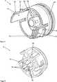
Der Förderkolben weist einen äußeren Sterilisationskolben
Wann immer im Folgenden Details zum Sterilisationskolben
Zwischen dem Dichtungskolben
An einer zylinderförmigen Außenwand des Sterilisationskolbens
Zwischen den beiden Schlitzen ist jeweils ein Rastelement
In den Kartuscheninnenwänden
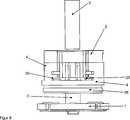
Der Dichtungskolben
Der Dichtungskolben
Der Dichtungskolben
Alternativ dazu, aber nicht in den
Das Verriegelungselement
Weiterhin kann erfindungsgemäß vorgesehen sein, dass der Dichtungskolben
Der Dichtungskolben
Eine vorteilhafte Ausgestaltung der Vorrichtung besteht darin, dass zwischen dem Verriegelungselement
Dabei kann vorgesehen sein, dass das Verriegelungselement
Das Verriegelungselement
Der Abstandhalter
Für die Funktion der Vorrichtung ist es vorteilhaft, dass das dreiteilige Kolbensystem
Eine Austragsöffnung der Kartusche
Der Mischstab
Außen um den Sterilisationskolben
Der Sterilisationskolben
Der Vakuumanschluss
Es sind in den
In der in
Anschließend wird der Abstandhalter
Danach wird das Verriegelungselement
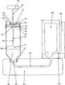
Ein Mischstab
Am oberen Ende des Mischstabs
Auf der anderen Seite des Trägers
Die Kartusche
Mit Hilfe des Öffnungsmechanismus
Anschließend wird der Förderkolben
Auf das Gewinde
Das erfindungsgemäße Knochenzementsystem mit der zuvor beschriebenen erfindungsgemäßen Vorrichtung zum Mischen und Austragen von Knochenzement, ist also zusammengesetzt aus einem Vorratselement
Das Basiselement
Das Vorratselement
Das Vorratselement
Das Basiselement
Die in der voranstehenden Beschreibung, sowie den Ansprüchen, Figuren und Ausführungsbeispielen offenbarten Merkmale der Erfindung können sowohl einzeln, als auch in jeder beliebigen Kombination für die Verwirklichung der Erfindung in ihren verschiedenen Ausführungsformen wesentlich sein.The features of the invention disclosed in the foregoing description, as well as the claims, figures and embodiments may be essential both individually and in any combination for the realization of the invention in its various embodiments.
BezugszeichenlisteLIST OF REFERENCE NUMBERS
- 11
- Mischelementmixing element
- 22
- MischstabMischstab
- 33
- Sterilisationskolbensterilization piston
- 44
- Dichtungskolbenseal piston
- 55
- Verriegelungselementlocking element
- 66
- Abstandhalter/SicherungselementSpacers / locking element
- 88th
- GriffHandle
- 99
- Kartuschecartridge
- 1010
- Rastmittellatching means
- 1212
- Streifenstrip
- 1414
- Griffstückgrip
- 1616
- Vakuumanschlussvacuum connection
- 1818
- Klemmbackejaw
- 2020
- Rastmittellatching means
- 2222
- SollbruchstelleBreaking point
- 24, 2624, 26
- Dichtungpoetry
- 2828
- Porenscheibepores disc
- 3030
- Verrippungribbing
- 3232
- Gaskanalgas channel
- 7878
- Klemmbacke mit DornJaw with thorn
- 7979
- Verriegelungselementlocking element
- 8080
- Kartuschecartridge
- 8181
- Förderkolbendelivery piston
- 8282
- Dichtungpoetry
- 8383
- Porenscheibepores disc
- 8484
- Abstreiflippewiping lip
- 8585
- Arretierungsvorrichtunglocking device
- 8787
- Vakuumanschlussvacuum connection
- 8888
- SollbruchstelleBreaking point
- 8989
- MischstabMischstab
- 9090
- Führungshülseguide sleeve
- 9191
- Mischelement/MischflügelMixing element / mixing blades
- 9292
- Kartuschenwandcartridge wall
- 9595
- GriffHandle
- 9696
- Austragsöffnungdischarge
- 9797
- Gewindethread
- 9898
- Leitungmanagement
- 9999
- Träger/BasiselelementCarrier / Basiselelement
- 100100
- Ampulleampoule
- 102102
- Behälter/VorratselementContainer / storage element
- 104104
- Öffnungsmechanismusopening mechanism
ZITATE ENTHALTEN IN DER BESCHREIBUNG QUOTES INCLUDE IN THE DESCRIPTION
Diese Liste der vom Anmelder aufgeführten Dokumente wurde automatisiert erzeugt und ist ausschließlich zur besseren Information des Lesers aufgenommen. Die Liste ist nicht Bestandteil der deutschen Patent- bzw. Gebrauchsmusteranmeldung. Das DPMA übernimmt keinerlei Haftung für etwaige Fehler oder Auslassungen.This list of the documents listed by the applicant has been generated automatically and is included solely for the better information of the reader. The list is not part of the German patent or utility model application. The DPMA assumes no liability for any errors or omissions.
Zitierte PatentliteraturCited patent literature
- US 6033105 A[0003]US 6033105 A[0003]
- US 5624184 A[0003]US 5624184 A[0003]
- US 4671263 A[0003]US 4671263 A[0003]
- US 4973168 A[0003]US 4973168 A[0003]
- US 5100241 A[0003]US 5,100,241 A[0003]
- WO 99/67015 A1[0003]WO 99/67015 Al[0003]
- EP 1020167 A2[0003]EP 1020167 A2[0003]
- US 5586821 A[0003]US 5586821 A[0003]
- EP 1016452 A2[0003]EP 1016452 A2[0003]
- DE 3640279 A1[0003]DE 3640279 A1[0003]
- WO 94/26403 A1[0003]WO 94/26403 A1[0003]
- EP 1005901 A2[0003]EP 1005901 A2[0003]
- US 5344232 A[0003]US 5344232 A[0003]
- EP 0692229 A1[0004]EP 0692229 A1[0004]
- DE 102009031178 B3[0006, 0010, 0011, 0011]DE 102009031178 B3[0006, 0010, 0011, 0011]
- DE 4302230 A1[0009]DE 4302230 A1[0009]
Claims (26)
Translated fromGermanPriority Applications (7)
| Application Number | Priority Date | Filing Date | Title |
|---|---|---|---|
| DE102012024710.9ADE102012024710A1 (en) | 2012-11-07 | 2012-12-18 | Device for mixing and discharging a pasty mass |
| CA2830629ACA2830629C (en) | 2012-11-07 | 2013-10-18 | Device for mixing and dispensing a pasty mass |
| EP13189552.6AEP2730332B1 (en) | 2012-11-07 | 2013-10-21 | Device for mixing and applying a paste-like mass |
| US14/066,169US9694514B2 (en) | 2012-11-07 | 2013-10-29 | Device for mixing and dispensing a pasty mass |
| JP2013225082AJP5756159B2 (en) | 2012-11-07 | 2013-10-30 | Device for mixing and dispensing pasty masses |
| AU2013254886AAU2013254886B2 (en) | 2012-11-07 | 2013-11-05 | Device for mixing and dispensing a pasty mass |
| CN201310669792.7ACN103801216B (en) | 2012-11-07 | 2013-11-07 | For mixing and distribute the device of pasty mass |
Applications Claiming Priority (3)
| Application Number | Priority Date | Filing Date | Title |
|---|---|---|---|
| DE102012021676 | 2012-11-07 | ||
| DE102012021676.9 | 2012-11-07 | ||
| DE102012024710.9ADE102012024710A1 (en) | 2012-11-07 | 2012-12-18 | Device for mixing and discharging a pasty mass |
Publications (1)
| Publication Number | Publication Date |
|---|---|
| DE102012024710A1true DE102012024710A1 (en) | 2014-05-08 |
Family
ID=49474253
Family Applications (1)
| Application Number | Title | Priority Date | Filing Date |
|---|---|---|---|
| DE102012024710.9ACeasedDE102012024710A1 (en) | 2012-11-07 | 2012-12-18 | Device for mixing and discharging a pasty mass |
Country Status (7)
| Country | Link |
|---|---|
| US (1) | US9694514B2 (en) |
| EP (1) | EP2730332B1 (en) |
| JP (1) | JP5756159B2 (en) |
| CN (1) | CN103801216B (en) |
| AU (1) | AU2013254886B2 (en) |
| CA (1) | CA2830629C (en) |
| DE (1) | DE102012024710A1 (en) |
Cited By (4)
| Publication number | Priority date | Publication date | Assignee | Title |
|---|---|---|---|---|
| DE102014109905A1 (en)* | 2014-07-15 | 2016-01-21 | Heraeus Medical Gmbh | Vacuum mixing system and method for mixing polymethyl methacrylate bone cement |
| DE102015112203A1 (en)* | 2015-07-27 | 2017-02-02 | Aap Biomaterials Gmbh | Mixing device, in particular for bone cement |
| EP3150155A1 (en)* | 2015-10-02 | 2017-04-05 | Heraeus Medical GmbH | Device and method for storing and mixing a bone cement |
| EP3695797A1 (en) | 2019-02-18 | 2020-08-19 | Heraeus Medical GmbH | Bone cement applicator with clampable discharge plunger |
Families Citing this family (13)
| Publication number | Priority date | Publication date | Assignee | Title |
|---|---|---|---|---|
| DE102015106899B3 (en)* | 2015-05-04 | 2016-07-14 | Heraeus Medical Gmbh | Device for mixing and storing polymethyl methacrylate bone cement |
| DE102015111320B4 (en)* | 2015-07-13 | 2018-10-18 | Heraeus Medical Gmbh | Vacuum mixing system and method for mixing polymethyl methacrylate bone cement |
| DE102015217315A1 (en)* | 2015-09-10 | 2017-03-16 | Heraeus Medical Gmbh | Adjustable initial viscosity polymethyl methacrylate bone cement and a method of making a variable initial viscosity bone cement dough |
| DE102016106261B4 (en)* | 2016-04-06 | 2018-03-15 | Heraeus Medical Gmbh | Device for mixing and storing polymethyl methacrylate bone cement with pressure pump and vial breaker |
| DE102016110561A1 (en) | 2016-06-08 | 2017-12-14 | Heraeus Medical Gmbh | Storage and mixing device for producing a bone cement |
| CN106671270B (en)* | 2017-01-06 | 2022-04-08 | 遂昌处州窑青瓷有限公司 | Ceramic mud kneading manipulator |
| WO2019046425A1 (en)* | 2017-08-29 | 2019-03-07 | Henkel IP & Holding GmbH | Fluid dispenser with zero displacement sealing device |
| US10856923B2 (en) | 2018-01-22 | 2020-12-08 | Warsaw Orthopedic, Inc. | Manual mixer |
| CN108479627B (en)* | 2018-06-12 | 2024-01-30 | 上海螭宿医药科技有限公司 | Medicine bottle clamping device and application method thereof |
| DE202018104763U1 (en)* | 2018-08-20 | 2018-09-06 | Heina Meyer | Mixing device for preparing a usable mass |
| EP3771495A1 (en)* | 2019-07-29 | 2021-02-03 | Sulzer Mixpac AG | Discharge arrangement, component, accessory, method of connecting an accessory to a component, and system |
| CN112294417A (en)* | 2020-12-10 | 2021-02-02 | 潘建康 | A tibia proximal bone cement compression device |
| EP4385613A1 (en)* | 2022-12-13 | 2024-06-19 | Heraeus Medical GmbH | Device for mixing bone cement |
Citations (14)
| Publication number | Priority date | Publication date | Assignee | Title |
|---|---|---|---|---|
| US4671263A (en) | 1984-07-11 | 1987-06-09 | Klaus Draenert | Device and process for mixing and applying bone cement |
| DE3640279A1 (en) | 1985-12-23 | 1987-06-25 | Mit Ab | DEVICE FOR MIXING BONE CEMENT IN A VACUUM |
| US4973168A (en) | 1989-01-13 | 1990-11-27 | Chan Kwan Ho | Vacuum mixing/bone cement cartridge and kit |
| DE4302230A1 (en) | 1992-02-07 | 1993-08-12 | Mit Ab | |
| US5344232A (en) | 1991-09-30 | 1994-09-06 | Stryker Corporation | Bone cement mixing and loading apparatus |
| WO1994026403A1 (en) | 1993-05-10 | 1994-11-24 | Cemvac System Ab | Method and device for feeding components for bone cement into a mixing vessel for these |
| EP0692229A1 (en) | 1994-07-16 | 1996-01-17 | MERCK PATENT GmbH | Mixing and dispensing device for bone cement |
| US5586821A (en) | 1995-10-10 | 1996-12-24 | Zimmer, Inc. | Bone cement preparation kit |
| WO1999067015A1 (en) | 1997-05-21 | 1999-12-29 | Nikomed Aps | An apparatus for preparing bone cement |
| US6033105A (en) | 1996-11-15 | 2000-03-07 | Barker; Donald | Integrated bone cement mixing and dispensing system |
| EP1005901A2 (en) | 1995-11-13 | 2000-06-07 | Cemvac System Aktiebolag | Method and device for mixing components for bone cement in a mixing vessel |
| EP1020167A2 (en) | 1999-01-14 | 2000-07-19 | Bristol-Myers Squibb Company | Apparatus and method for mixing and dispensing bone cement |
| WO2009105905A1 (en)* | 2008-02-28 | 2009-09-03 | Medmix Systems Ag | Single chamber device for drawing in and dispensing components |
| DE102009031178B3 (en)* | 2009-06-29 | 2010-09-16 | Heraeus Medical Gmbh | Device for mixing and delivering bone cement |
Family Cites Families (9)
| Publication number | Priority date | Publication date | Assignee | Title |
|---|---|---|---|---|
| US3475010A (en)* | 1968-04-24 | 1969-10-28 | Prod Res & Chem Corp | Dispensing cartridge for intermixing separate ingredients |
| US6547432B2 (en) | 2001-07-16 | 2003-04-15 | Stryker Instruments | Bone cement mixing and delivery device for injection and method thereof |
| EP2839872B1 (en) | 2003-05-12 | 2018-03-07 | Stryker Corporation | Delivery gun for dispensing bone cement from a cartridge, the gun having a multi-link linkage capable of dispensing the cement at different flow rates |
| US20040267272A1 (en) | 2003-05-12 | 2004-12-30 | Henniges Bruce D | Bone cement mixing and delivery system |
| US7524103B2 (en) | 2003-11-18 | 2009-04-28 | Boston Scientific Scimed, Inc. | Apparatus for mixing and dispensing a multi-component bone cement |
| SE527528C2 (en)* | 2004-06-22 | 2006-04-04 | Bone Support Ab | Apparatus for the preparation of curable pulp and use of the apparatus |
| US8480289B2 (en)* | 2008-08-22 | 2013-07-09 | Biomet Manufacturing, Llc | Bone cement mixing cartridge and method of use |
| KR101152182B1 (en) | 2010-05-04 | 2012-06-15 | 주식회사디아이 | Probe film used probe block and method for manufacturing thereof |
| DE102010052323A1 (en) | 2010-11-25 | 2012-05-31 | Heraeus Medical Gmbh | Cartridge with lockable delivery piston |
- 2012
- 2012-12-18DEDE102012024710.9Apatent/DE102012024710A1/ennot_activeCeased
- 2013
- 2013-10-18CACA2830629Apatent/CA2830629C/ennot_activeExpired - Fee Related
- 2013-10-21EPEP13189552.6Apatent/EP2730332B1/enactiveActive
- 2013-10-29USUS14/066,169patent/US9694514B2/enactiveActive
- 2013-10-30JPJP2013225082Apatent/JP5756159B2/enactiveActive
- 2013-11-05AUAU2013254886Apatent/AU2013254886B2/enactiveActive
- 2013-11-07CNCN201310669792.7Apatent/CN103801216B/enactiveActive
Patent Citations (17)
| Publication number | Priority date | Publication date | Assignee | Title |
|---|---|---|---|---|
| US4671263A (en) | 1984-07-11 | 1987-06-09 | Klaus Draenert | Device and process for mixing and applying bone cement |
| DE3640279A1 (en) | 1985-12-23 | 1987-06-25 | Mit Ab | DEVICE FOR MIXING BONE CEMENT IN A VACUUM |
| US4973168A (en) | 1989-01-13 | 1990-11-27 | Chan Kwan Ho | Vacuum mixing/bone cement cartridge and kit |
| US5100241A (en) | 1989-01-13 | 1992-03-31 | Chan Kwan Ho | Vacuum mixing/bone cement cartridge and kit |
| US5344232A (en) | 1991-09-30 | 1994-09-06 | Stryker Corporation | Bone cement mixing and loading apparatus |
| DE4302230A1 (en) | 1992-02-07 | 1993-08-12 | Mit Ab | |
| WO1994026403A1 (en) | 1993-05-10 | 1994-11-24 | Cemvac System Ab | Method and device for feeding components for bone cement into a mixing vessel for these |
| EP0692229A1 (en) | 1994-07-16 | 1996-01-17 | MERCK PATENT GmbH | Mixing and dispensing device for bone cement |
| US5586821A (en) | 1995-10-10 | 1996-12-24 | Zimmer, Inc. | Bone cement preparation kit |
| US5624184A (en) | 1995-10-10 | 1997-04-29 | Chan; Kwan-Ho | Bone cement preparation kit having a breakable mixing shaft forming an output port |
| EP1005901A2 (en) | 1995-11-13 | 2000-06-07 | Cemvac System Aktiebolag | Method and device for mixing components for bone cement in a mixing vessel |
| EP1016452A2 (en) | 1995-11-13 | 2000-07-05 | Cemvac System Aktiebolag | Method and device for mixing components for bone cement in a mixing vessel |
| US6033105A (en) | 1996-11-15 | 2000-03-07 | Barker; Donald | Integrated bone cement mixing and dispensing system |
| WO1999067015A1 (en) | 1997-05-21 | 1999-12-29 | Nikomed Aps | An apparatus for preparing bone cement |
| EP1020167A2 (en) | 1999-01-14 | 2000-07-19 | Bristol-Myers Squibb Company | Apparatus and method for mixing and dispensing bone cement |
| WO2009105905A1 (en)* | 2008-02-28 | 2009-09-03 | Medmix Systems Ag | Single chamber device for drawing in and dispensing components |
| DE102009031178B3 (en)* | 2009-06-29 | 2010-09-16 | Heraeus Medical Gmbh | Device for mixing and delivering bone cement |
Cited By (13)
| Publication number | Priority date | Publication date | Assignee | Title |
|---|---|---|---|---|
| DE102014109905A1 (en)* | 2014-07-15 | 2016-01-21 | Heraeus Medical Gmbh | Vacuum mixing system and method for mixing polymethyl methacrylate bone cement |
| DE102014109905B4 (en) | 2014-07-15 | 2017-02-09 | Heraeus Medical Gmbh | Vacuum mixing system and method for mixing polymethyl methacrylate bone cement |
| US10307508B2 (en) | 2014-07-15 | 2019-06-04 | Heraeus Medical Gmbh | Vacuum mixing system and method for the mixing of polymethylmethacrylate bone cement |
| DE102015112203A1 (en)* | 2015-07-27 | 2017-02-02 | Aap Biomaterials Gmbh | Mixing device, in particular for bone cement |
| EP3127601A1 (en)* | 2015-07-27 | 2017-02-08 | AAP Biomaterials GmbH | Mixing device, in particular for bone cement |
| US11033866B2 (en) | 2015-07-27 | 2021-06-15 | Osartis Gmbh | Mixing device for bone cement |
| DE102015116797B4 (en) | 2015-10-02 | 2018-08-23 | Heraeus Medical Gmbh | Apparatus and method for storing and mixing a bone cement |
| DE102015116797A1 (en)* | 2015-10-02 | 2017-04-06 | Heraeus Medical Gmbh | Apparatus and method for storing and mixing a bone cement |
| US10307195B2 (en) | 2015-10-02 | 2019-06-04 | Heraeus Medical Gmbh | Device and method for storing and mixing a bone cement |
| EP3150155A1 (en)* | 2015-10-02 | 2017-04-05 | Heraeus Medical GmbH | Device and method for storing and mixing a bone cement |
| EP3695797A1 (en) | 2019-02-18 | 2020-08-19 | Heraeus Medical GmbH | Bone cement applicator with clampable discharge plunger |
| DE102019104020A1 (en)* | 2019-02-18 | 2020-08-20 | Heraeus Medical Gmbh | Bone cement applicator with clampable discharge piston |
| US11701156B2 (en) | 2019-02-18 | 2023-07-18 | Heraeus Medical Gmbh | Bone cement applicator with clampable delivery plunger |
Also Published As
| Publication number | Publication date |
|---|---|
| CA2830629C (en) | 2016-01-19 |
| US9694514B2 (en) | 2017-07-04 |
| CN103801216A (en) | 2014-05-21 |
| EP2730332A3 (en) | 2017-06-21 |
| CN103801216B (en) | 2017-06-23 |
| EP2730332B1 (en) | 2019-07-31 |
| AU2013254886B2 (en) | 2015-04-16 |
| EP2730332A2 (en) | 2014-05-14 |
| CA2830629A1 (en) | 2014-05-07 |
| JP5756159B2 (en) | 2015-07-29 |
| JP2014121520A (en) | 2014-07-03 |
| US20140126320A1 (en) | 2014-05-08 |
| AU2013254886A1 (en) | 2014-05-22 |
Similar Documents
| Publication | Publication Date | Title |
|---|---|---|
| EP2730332B1 (en) | Device for mixing and applying a paste-like mass | |
| EP3320870B1 (en) | Device and method for storing and mixing of a bone cement | |
| EP2384820B1 (en) | Cartridge system and application tube for such a cartridge system | |
| EP2618759B1 (en) | Mixing device for prepack vacuum cementing system, vacuum cementing system and method | |
| EP2883603B1 (en) | Device for storing and mixing bone cement | |
| EP2974681B1 (en) | Vacuum mixing system and method for mixing of polymethylmethacrylate bone cement | |
| EP3395274B1 (en) | Bone cement application device with closure means at the output piston | |
| DE102015116797B4 (en) | Apparatus and method for storing and mixing a bone cement | |
| EP2457531B1 (en) | Cartridge with adjustable delivery pistons | |
| DE102017107569A1 (en) | Device for storing, mixing and discharging a bone cement and method therefor | |
| EP3100694B1 (en) | Device and method for mixing and storing polymethymethacrylate bone cement | |
| EP3403716A1 (en) | Bone cement applicator with hollow cylinder at the application piston | |
| EP1520562B1 (en) | Device for mixing and delivering of liquid and powdery substances for medical use. | |
| DE102014101305A1 (en) | Device for storing and mixing bone cement | |
| EP3584005A1 (en) | Bone cement applicator with retractable mixing rod and method for producing a bone cement | |
| DE102010026497A1 (en) | Method of opening a container, container opening system and vacuum cementing system | |
| EP3479895B1 (en) | Powder liquid bone cement mixer with connector for pressurised gas and method | |
| EP3415226B1 (en) | Bone cement applicator with conduit element and closure holder | |
| EP3584004A1 (en) | Bone cement applicator with retractable mixing rod and method for producing a bone cement | |
| EP3505237A1 (en) | Bone cement mixing apparatus and method with spacer in an ampoule holder | |
| DE102019104020A1 (en) | Bone cement applicator with clampable discharge piston |
Legal Events
| Date | Code | Title | Description |
|---|---|---|---|
| R012 | Request for examination validly filed | ||
| R016 | Response to examination communication | ||
| R002 | Refusal decision in examination/registration proceedings | ||
| R082 | Change of representative | Representative=s name:EULER, MATTHIAS, DR., DE | |
| R003 | Refusal decision now final |