DE102012023363B4 - Subframe for a motor vehicle - Google Patents
Subframe for a motor vehicleDownload PDFInfo
- Publication number
- DE102012023363B4 DE102012023363B4DE102012023363.9ADE102012023363ADE102012023363B4DE 102012023363 B4DE102012023363 B4DE 102012023363B4DE 102012023363 ADE102012023363 ADE 102012023363ADE 102012023363 B4DE102012023363 B4DE 102012023363B4
- Authority
- DE
- Germany
- Prior art keywords
- subframe
- motor vehicle
- stiffening structure
- coil unit
- vehicle
- Prior art date
- Legal status (The legal status is an assumption and is not a legal conclusion. Google has not performed a legal analysis and makes no representation as to the accuracy of the status listed.)
- Expired - Fee Related
Links
- 230000001965increasing effectEffects0.000claimsabstractdescription6
- 230000005540biological transmissionEffects0.000abstractdescription8
- 230000005294ferromagnetic effectEffects0.000description3
- XAGFODPZIPBFFR-UHFFFAOYSA-NaluminiumChemical compound[Al]XAGFODPZIPBFFR-UHFFFAOYSA-N0.000description2
- 229910052782aluminiumInorganic materials0.000description2
- 238000007599dischargingMethods0.000description2
- 230000005291magnetic effectEffects0.000description2
- 230000002411adverseEffects0.000description1
- 238000005452bendingMethods0.000description1
- 238000010276constructionMethods0.000description1
- 230000008878couplingEffects0.000description1
- 238000010168coupling processMethods0.000description1
- 238000005859coupling reactionMethods0.000description1
- 230000000694effectsEffects0.000description1
- 230000001939inductive effectEffects0.000description1
- 230000003993interactionEffects0.000description1
- 239000000463materialSubstances0.000description1
- 230000008092positive effectEffects0.000description1
- 239000000725suspensionSubstances0.000description1
Images

Classifications
- B—PERFORMING OPERATIONS; TRANSPORTING
- B62—LAND VEHICLES FOR TRAVELLING OTHERWISE THAN ON RAILS
- B62D—MOTOR VEHICLES; TRAILERS
- B62D21/00—Understructures, i.e. chassis frame on which a vehicle body may be mounted
- B—PERFORMING OPERATIONS; TRANSPORTING
- B60—VEHICLES IN GENERAL
- B60L—PROPULSION OF ELECTRICALLY-PROPELLED VEHICLES; SUPPLYING ELECTRIC POWER FOR AUXILIARY EQUIPMENT OF ELECTRICALLY-PROPELLED VEHICLES; ELECTRODYNAMIC BRAKE SYSTEMS FOR VEHICLES IN GENERAL; MAGNETIC SUSPENSION OR LEVITATION FOR VEHICLES; MONITORING OPERATING VARIABLES OF ELECTRICALLY-PROPELLED VEHICLES; ELECTRIC SAFETY DEVICES FOR ELECTRICALLY-PROPELLED VEHICLES
- B60L53/00—Methods of charging batteries, specially adapted for electric vehicles; Charging stations or on-board charging equipment therefor; Exchange of energy storage elements in electric vehicles
- B60L53/10—Methods of charging batteries, specially adapted for electric vehicles; Charging stations or on-board charging equipment therefor; Exchange of energy storage elements in electric vehicles characterised by the energy transfer between the charging station and the vehicle
- B60L53/12—Inductive energy transfer
- B—PERFORMING OPERATIONS; TRANSPORTING
- B62—LAND VEHICLES FOR TRAVELLING OTHERWISE THAN ON RAILS
- B62D—MOTOR VEHICLES; TRAILERS
- B62D21/00—Understructures, i.e. chassis frame on which a vehicle body may be mounted
- B62D21/11—Understructures, i.e. chassis frame on which a vehicle body may be mounted with resilient means for suspension, e.g. of wheels or engine; sub-frames for mounting engine or suspensions
- B—PERFORMING OPERATIONS; TRANSPORTING
- B62—LAND VEHICLES FOR TRAVELLING OTHERWISE THAN ON RAILS
- B62D—MOTOR VEHICLES; TRAILERS
- B62D21/00—Understructures, i.e. chassis frame on which a vehicle body may be mounted
- B62D21/15—Understructures, i.e. chassis frame on which a vehicle body may be mounted having impact absorbing means, e.g. a frame designed to permanently or temporarily change shape or dimension upon impact with another body
- Y—GENERAL TAGGING OF NEW TECHNOLOGICAL DEVELOPMENTS; GENERAL TAGGING OF CROSS-SECTIONAL TECHNOLOGIES SPANNING OVER SEVERAL SECTIONS OF THE IPC; TECHNICAL SUBJECTS COVERED BY FORMER USPC CROSS-REFERENCE ART COLLECTIONS [XRACs] AND DIGESTS
- Y02—TECHNOLOGIES OR APPLICATIONS FOR MITIGATION OR ADAPTATION AGAINST CLIMATE CHANGE
- Y02T—CLIMATE CHANGE MITIGATION TECHNOLOGIES RELATED TO TRANSPORTATION
- Y02T10/00—Road transport of goods or passengers
- Y02T10/60—Other road transportation technologies with climate change mitigation effect
- Y02T10/70—Energy storage systems for electromobility, e.g. batteries
- Y—GENERAL TAGGING OF NEW TECHNOLOGICAL DEVELOPMENTS; GENERAL TAGGING OF CROSS-SECTIONAL TECHNOLOGIES SPANNING OVER SEVERAL SECTIONS OF THE IPC; TECHNICAL SUBJECTS COVERED BY FORMER USPC CROSS-REFERENCE ART COLLECTIONS [XRACs] AND DIGESTS
- Y02—TECHNOLOGIES OR APPLICATIONS FOR MITIGATION OR ADAPTATION AGAINST CLIMATE CHANGE
- Y02T—CLIMATE CHANGE MITIGATION TECHNOLOGIES RELATED TO TRANSPORTATION
- Y02T10/00—Road transport of goods or passengers
- Y02T10/60—Other road transportation technologies with climate change mitigation effect
- Y02T10/7072—Electromobility specific charging systems or methods for batteries, ultracapacitors, supercapacitors or double-layer capacitors
- Y—GENERAL TAGGING OF NEW TECHNOLOGICAL DEVELOPMENTS; GENERAL TAGGING OF CROSS-SECTIONAL TECHNOLOGIES SPANNING OVER SEVERAL SECTIONS OF THE IPC; TECHNICAL SUBJECTS COVERED BY FORMER USPC CROSS-REFERENCE ART COLLECTIONS [XRACs] AND DIGESTS
- Y02—TECHNOLOGIES OR APPLICATIONS FOR MITIGATION OR ADAPTATION AGAINST CLIMATE CHANGE
- Y02T—CLIMATE CHANGE MITIGATION TECHNOLOGIES RELATED TO TRANSPORTATION
- Y02T90/00—Enabling technologies or technologies with a potential or indirect contribution to GHG emissions mitigation
- Y02T90/10—Technologies relating to charging of electric vehicles
- Y02T90/12—Electric charging stations
- Y—GENERAL TAGGING OF NEW TECHNOLOGICAL DEVELOPMENTS; GENERAL TAGGING OF CROSS-SECTIONAL TECHNOLOGIES SPANNING OVER SEVERAL SECTIONS OF THE IPC; TECHNICAL SUBJECTS COVERED BY FORMER USPC CROSS-REFERENCE ART COLLECTIONS [XRACs] AND DIGESTS
- Y02—TECHNOLOGIES OR APPLICATIONS FOR MITIGATION OR ADAPTATION AGAINST CLIMATE CHANGE
- Y02T—CLIMATE CHANGE MITIGATION TECHNOLOGIES RELATED TO TRANSPORTATION
- Y02T90/00—Enabling technologies or technologies with a potential or indirect contribution to GHG emissions mitigation
- Y02T90/10—Technologies relating to charging of electric vehicles
- Y02T90/14—Plug-in electric vehicles
Landscapes
- Engineering & Computer Science (AREA)
- Transportation (AREA)
- Mechanical Engineering (AREA)
- Chemical & Material Sciences (AREA)
- Combustion & Propulsion (AREA)
- Power Engineering (AREA)
- Body Structure For Vehicles (AREA)
- Current-Collector Devices For Electrically Propelled Vehicles (AREA)
- Arrangement Or Mounting Of Propulsion Units For Vehicles (AREA)
- Electric Propulsion And Braking For Vehicles (AREA)
Abstract
Translated fromGermanDescription
Translated fromGermanDie vorliegende Erfindung betrifft einen Hilfsrahmen eines Vorder- oder Hinterwagens eines Kraftfahrzeugs mit zwei Längsträgern, die in Fahrzeugquerrichtung voneinander beabstandet und über wenigstens einen Querträger miteinander verbunden sind, wobei der Hilfsrahmen eine Versteifungsstruktur zur Erhöhung der Torsionssteifigkeit aufweist, sowie ein Kraftfahrzeug mit einem solchen Hilfsrahmen.The present invention relates to a subframe of a front or rear carriage of a motor vehicle with two longitudinal members, which are spaced apart in the vehicle transverse direction and interconnected via at least one cross member, wherein the subframe has a stiffening structure to increase the torsional rigidity, as well as a motor vehicle with such a subframe.
Derartige Hilfsrahmen dienen im Kraftfahrzeugbau der Befestigung der aufbauseitigen Anlenkpunkte einer Radaufhängung. Zumeist am Hilfsrahmen des Vorderwagens können zusätzlich auch eine Kraftmaschine, ein Getriebe und/oder eine Lenkung befestigt sein. Der Hilfsrahmen selbst wird in der Regel elastisch mittels Gummilagern an die Karosserie angebunden. Die Versteifungsstruktur kann wahlweise als schubsteife Platte oder als, vorzugsweise kreuzartiger, Strebenverbund ausgebildet sein. Durch die schubsteife Platte kann lediglich die Steifigkeit des Hilfsrahmens erhöht werden, während der Strebenverbund zusätzlich noch in der Lage ist Kräfte aufzunehmen.Such subframes are used in motor vehicle mounting of the body-side pivot points of a suspension. In most cases, on the subframe of the front end, an engine, a transmission and / or a steering can also be attached. The subframe itself is usually connected elastically by means of rubber bearings to the body. The stiffening structure may optionally be designed as a shear-resistant plate or as, preferably cross-like, strut assembly. Due to the shear-resistant plate, only the rigidity of the subframe can be increased, while the strut assembly is additionally able to absorb forces.
Die gattungsbildenden Druckschriften
Die
Aufgabe der vorliegenden Erfindung ist es daher, einen Hilfsrahmen für ein Kraftfahrzeug und ein Kraftfahrzeug mit einem solchen Hilfsrahmen bereitzustellen, dessen Versteifungsstruktur für weitere Funktionen genutzt werden kann.Object of the present invention is therefore to provide a subframe for a motor vehicle and a motor vehicle with such a subframe, the stiffening structure can be used for other functions.
Diese Aufgabe wird durch die Merkmale der Patentansprüche 1 und 7 gelöst.This object is solved by the features of
Ein Kraftfahrzeug mit einem erfindungsgemäßen Hilfsrahmen ist in Patentanspruch 7 beansprucht.A motor vehicle with a subframe according to the invention is claimed in claim 7.
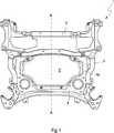
Ein Hilfsrahmen eines Vorder- oder Hinterwagens eines Kraftfahrzeugs hat zwei Längsträger, die in Fahrzeugquerrichtung voneinander beabstandet und über wenigstens einen Querträger miteinander verbunden sind, wobei der Hilfsrahmen eine Versteifungsstruktur zur Erhöhung der Torsionssteifigkeit aufweist und wobei ein Lademodul zur kontaktlosen Energieübertragung in die Versteifungsstruktur integrierbar ist.An auxiliary frame of a front or rear carriage of a motor vehicle has two side members, which are spaced apart in the vehicle transverse direction and interconnected via at least one cross member, wherein the subframe has a stiffening structure to increase the torsional stiffness and wherein a loading module for contactless energy transfer is integrated into the stiffening structure.
Indem das Lademodul in die Versteifungsstruktur integriert wird, kann der ohnehin benötigte Bauraum zur Aussteifung des Hilfsrahmens für eine weitere Funktion, nämlich die kontaktlose Energieübertragung auf das Kraftfahrzeug, genutzt werden. Dadurch verringert sich insgesamt der Bauraumbedarf, vor allem in Fahrzeughochrichtung. Das Lademodul ist als fahrzeugseitiger Teil eines Systems zur kontaktlosen Energieübertragung zu verstehen, wie es exemplarisch in den Druckschriften
Die Längsträger des Hilfsrahmens sind vorzugsweise spiegelsymmetrisch angeordnet und können entweder unmittelbar oder mittelbar, beispielsweise über einen Gussknoten, mit dem mindestens einen Querträger zu einer offenen bzw. geschlossenen Rahmenkonstruktion verbunden werden.The longitudinal members of the subframe are preferably arranged mirror-symmetrically and can be connected either directly or indirectly, for example via a cast node, with the at least one cross member to form an open or closed frame construction.
In einer bevorzugten Ausführung weist die Versteifungsstruktur eine Freifläche auf, die von dem Lademodul zumindest teilweise ausgefüllt wird. Die Freifläche stellt eine Aussparung vom Material in der Versteifungsstruktur dar und ist vorzugsweise zentral angeordnet. Das Lademodul wird in diese Freifläche eingesetzt, wodurch der Bauraumbedarf in Fahrzeughochrichtung minimal ist. Es ist insbesondere anzustreben, dass Lademodul und Versteifungsstruktur im eingebauten Zustand auf der Unterseite flächenbündig abschließen, um die Bodenfreiheit nicht negativ zu beeinträchtigen.In a preferred embodiment, the stiffening structure on an open space, which is at least partially filled by the loading module. The relief surface is a recess of the material in the stiffening structure and is preferably centrally located. The loading module is used in this free space, whereby the space requirement in the vehicle vertical direction is minimal. It is particularly desirable that the charging module and stiffening structure in the installed state on the bottom flush to complete, so as not to adversely affect the ground clearance.
In einer bevorzugten Ausführung weist das Lademodul ein Abschirmblech und eine Spuleneinheit auf. Zur besseren Funktion der Spuleneinheit ist eine Abschirmung gegenüber umliegenden ferro-magnetischen Bauteilen (beispielsweise Längsträger, Querträger und Versteifungsstruktur) notwendig. Zu diesem Zweck wird die Spuleneinheit von einem vorzugsweise aus Aluminium bestehenden Abschirmblech teilweise eingefasst und zwar so, dass das Abschirmblech sich zwischen den ferro-magnetischen Bauteilen und der Spuleneinheit befindet. Die Spuleneinheit wird während des Betriebs von einem magnetischen Wechselfeld des (geostationären) Transmitters zumindest teilweise durchdrungen, wodurch eine Spannung induziert wird. Eine geeignete Leistungselektronik wandelt diese Spannung, und gibt sie an das Bordnetz des Kraftfahrzeugs weiter.In a preferred embodiment, the charging module has a shielding plate and a coil unit. For better function of the coil unit shielding against surrounding ferro-magnetic components (such as side members, cross member and stiffening structure) is necessary. For this purpose, the coil unit is partially enclosed by a shielding plate, preferably made of aluminum, in such a way that the shielding plate is located between the ferromagnetic components and the coil unit. The coil unit is at least partially penetrated during operation by an alternating magnetic field of the (geostationary) transmitter, whereby a voltage is induced. A suitable power electronics converts this voltage, and passes them to the electrical system of the motor vehicle.
In einer bevorzugten Ausführung ist das Abschirmblech mit der Versteifungsstruktur verbunden. Die von der Versteifungsstruktur aufgenommenen Kräfte und Momente werden somit in das Abschirmblech weitergeleitet, was sich positiv auf die Torsions- bzw. Festigkeitseigenschaften des Hilfsrahmens auswirkt. Durch das Entkopplungselement zwischen Abschirmblech und Spuleneinheit ist letztere vor Beschädigungen durch die dabei entstehenden Verformungen des Abschirmblechs geschützt.In a preferred embodiment, the shielding plate is connected to the stiffening structure. The forces and moments taken up by the stiffening structure are thus transferred to the shielding plate, which has a positive effect on the torsional or strength properties of the subframe. The decoupling element between the shielding plate and the coil unit protects the latter from being damaged by the resulting deformations of the shielding plate.
In einer bevorzugten Ausführung ist zwischen Abschirmblech und Spuleneinheit ein Entkopplungselement angeordnet. Die Spuleneinheit ist in der Regel sehr empfindlich gegenüber Biegung und Torsion, die beim Fahrbetrieb im Abschirmblech entstehen können, weshalb eine (gummi-)elastische Lagerung der Spuleneinheit an dem Abschirmblech durch ein Entkopplungselement vorteilhaft ist.In a preferred embodiment, a decoupling element is arranged between the shielding plate and the coil unit. The coil unit is usually very sensitive to bending and torsion, which may arise during driving in the shield, which is why a (rubber) elastic mounting of the coil unit to the shield by a decoupling element is advantageous.
In einer bevorzugten Ausführung ist die Spuleneinheit in Einbaulage geodätisch unterhalb des Abschirmblechs angeordnet. Damit ist ein optimales Zusammenspiel mit einem fahrbahnseitigen Transmitter gewährleistet, während das Abschirmblech gegenüber den ferro-magnetischen Bauteilen des Kraftfahrzeugs nach oben hin abschirmt.In a preferred embodiment, the coil unit is arranged in the installed position geodetically below the shielding plate. This ensures optimum interaction with a roadside transmitter, while the shielding shields towards the top of the ferro-magnetic components of the motor vehicle.
Bei einem Kraftfahrzeug mit einem erfindungsgemäßen Hilfsrahmen ist das Lademodul mit einem elektrischen Energiespeicher verbunden. In einer bevorzugten Ausführung ist der Energiespeicher als Traktionsbatterie ausgebildet. Wird das Kraftfahrzeug nun über einen geostationären, fahrbahnseitigen Transmitter bewegt, so empfängt die Spuleneinheit des Lademoduls in der Versteifungsstruktur des Hilfsrahmens das vom Transmitter ausgesendete magnetische Wechselfeld und eine Spannung wird induziert. Die Spannung gibt die Leistungselektronik an die Traktionsbatterie weiter, die dadurch geladen wird. Zur Fortbewegung des Kraftfahrzeugs kann die Spannung später wieder aus der Traktionsbatterie entnommen werden, um eine E-Maschine anzutreiben.In a motor vehicle with a subframe according to the invention, the charging module is connected to an electrical energy store. In a preferred embodiment, the energy store is designed as a traction battery. If the motor vehicle is now moved via a geostationary, roadside transmitter, the coil unit of the charging module in the stiffening structure of the subframe receives the alternating magnetic field emitted by the transmitter and a voltage is induced. The voltage passes the power electronics to the traction battery, which is thereby charged. To move the motor vehicle, the voltage can later be removed again from the traction battery in order to drive an electric motor.
Weitere Einzelheiten und Vorteile der Erfindung ergeben sich aus der nachstehenden Beschreibung eines bevorzugten Ausführungsbeispiels unter Bezugnahme auf die Zeichnungen.Further details and advantages of the invention will become apparent from the following description of a preferred embodiment with reference to the drawings.
Darin zeigen:Show:
Gemäß
Die
BezugszeichenlisteLIST OF REFERENCE NUMBERS
- A-AA-A
- Symmetrielinieline of symmetry
- 11
- Hilfsrahmensubframe
- 22
- Längsträgerlongitudinal beams
- 33
- Querträgercrossbeam
- 44
- Versteifungsstrukturstiffening structure
- 4a4a
- Freiflächeopen space
- 55
- Lademodulloading module
- 5a5a
- Abschirmblechshield
- 5b5b
- Spuleneinheitcoil unit
- 5c5c
- Entkopplungselementdecoupling element
Claims (8)
Translated fromGermanPriority Applications (6)
| Application Number | Priority Date | Filing Date | Title |
|---|---|---|---|
| DE102012023363.9ADE102012023363B4 (en) | 2012-11-29 | 2012-11-29 | Subframe for a motor vehicle |
| EP13193659.3AEP2738069B1 (en) | 2012-11-29 | 2013-11-20 | Subframe for a motor vehicle |
| US14/092,192US9120506B2 (en) | 2012-11-29 | 2013-11-27 | Subframe for a motor vehicle |
| KR1020130145008AKR101661799B1 (en) | 2012-11-29 | 2013-11-27 | Subframe for motor vehicle |
| JP2013245525AJP5822896B2 (en) | 2012-11-29 | 2013-11-28 | Car subframe |
| CN201310628739.2ACN103847795B (en) | 2012-11-29 | 2013-11-29 | The subframe of motor vehicles |
Applications Claiming Priority (1)
| Application Number | Priority Date | Filing Date | Title |
|---|---|---|---|
| DE102012023363.9ADE102012023363B4 (en) | 2012-11-29 | 2012-11-29 | Subframe for a motor vehicle |
Publications (2)
| Publication Number | Publication Date |
|---|---|
| DE102012023363A1 DE102012023363A1 (en) | 2014-06-05 |
| DE102012023363B4true DE102012023363B4 (en) | 2014-06-26 |
Family
ID=49585325
Family Applications (1)
| Application Number | Title | Priority Date | Filing Date |
|---|---|---|---|
| DE102012023363.9AExpired - Fee RelatedDE102012023363B4 (en) | 2012-11-29 | 2012-11-29 | Subframe for a motor vehicle |
Country Status (6)
| Country | Link |
|---|---|
| US (1) | US9120506B2 (en) |
| EP (1) | EP2738069B1 (en) |
| JP (1) | JP5822896B2 (en) |
| KR (1) | KR101661799B1 (en) |
| CN (1) | CN103847795B (en) |
| DE (1) | DE102012023363B4 (en) |
Families Citing this family (49)
| Publication number | Priority date | Publication date | Assignee | Title |
|---|---|---|---|---|
| JP5857795B2 (en)* | 2011-05-17 | 2016-02-10 | 日産自動車株式会社 | Non-contact charger mounting structure |
| DE102013001094A1 (en) | 2013-01-23 | 2014-07-24 | Audi Ag | Motor vehicle with electrical energy storage and charging cable and method for operating a motor vehicle |
| DE102013002704A1 (en) | 2013-02-16 | 2014-08-21 | Audi Ag | Torsion bar system for a vehicle axle of a two-lane vehicle |
| DE102013007981A1 (en) | 2013-05-10 | 2014-11-13 | Audi Ag | Device for generating a pulse on a vehicle in a vehicle transverse direction |
| DE102013016758A1 (en)* | 2013-10-10 | 2015-04-16 | Audi Ag | Subframe for a motor vehicle |
| AU2014370931A1 (en)* | 2013-12-27 | 2016-07-14 | Honda Motor Co.,Ltd. | Sub-frame structure |
| DE102014004166A1 (en) | 2014-03-22 | 2015-09-24 | Audi Ag | Motor vehicle and rear module for this |
| DE102014206739A1 (en) | 2014-04-08 | 2015-10-08 | Bayerische Motoren Werke Aktiengesellschaft | Push panel for a front end of a vehicle body of a vehicle and vehicle |
| DE102014010287B3 (en)* | 2014-07-11 | 2015-06-25 | Audi Ag | Subframe for a motor vehicle |
| DE102014214917B4 (en)* | 2014-07-30 | 2018-12-20 | Volkswagen Aktiengesellschaft | Modular subframe for a wheel axle of a subframe |
| DE102014222000A1 (en)* | 2014-10-29 | 2016-05-04 | Bayerische Motoren Werke Aktiengesellschaft | Method and ground unit for inductive charging of electric and hybrid vehicles |
| JP6227575B2 (en)* | 2015-02-18 | 2017-11-08 | 豊田鉄工株式会社 | Automotive battery frame |
| DE102015207402A1 (en)* | 2015-04-23 | 2016-10-27 | Bayerische Motoren Werke Aktiengesellschaft | Axle carrier for a vehicle |
| GB2526434A (en) | 2015-05-04 | 2015-11-25 | Daimler Ag | Subframe for a vehicle, in particular a passenger vehicle |
| FR3038869B1 (en)* | 2015-07-17 | 2017-07-28 | Renault Sas | MOTOR VEHICLE WITH ELECTRICAL OR HYBRID TRACTION WITH NON-CONTACT REFILL |
| US10252631B2 (en) | 2015-11-13 | 2019-04-09 | Nio Usa, Inc. | Communications between vehicle and charging system |
| US10427530B2 (en) | 2015-11-13 | 2019-10-01 | Nio Usa, Inc. | Vehicle charge query and exchange system and method of use |
| US10189363B2 (en) | 2015-11-13 | 2019-01-29 | Nio Usa, Inc. | Electric vehicle roadway charging system and method of use |
| US10532663B2 (en) | 2015-11-13 | 2020-01-14 | Nio Usa, Inc. | Electric vehicle overhead charging system and method of use |
| US10160339B2 (en) | 2015-11-13 | 2018-12-25 | Nio Usa, Inc. | Smart grid management |
| US10093195B2 (en) | 2015-11-13 | 2018-10-09 | Nio Usa, Inc. | Integrated vehicle charging panel system and method of use |
| US10131238B2 (en) | 2015-11-13 | 2018-11-20 | Nio Usa, Inc. | Charging transmission line under roadway for moving electric vehicle |
| US10166875B2 (en) | 2015-11-13 | 2019-01-01 | Nio Usa, Inc. | Deployable safety shield for charging |
| US10220717B2 (en)* | 2015-11-13 | 2019-03-05 | Nio Usa, Inc. | Electric vehicle emergency charging system and method of use |
| US10080318B2 (en) | 2015-11-13 | 2018-09-18 | Nio Usa, Inc. | Safety shield for charging |
| US10059213B2 (en) | 2015-11-13 | 2018-08-28 | Nio Usa, Inc. | Charging devices within wheel portions |
| US10336194B2 (en) | 2015-11-13 | 2019-07-02 | Nio Usa, Inc. | Electric vehicle charging device alignment and method of use |
| US9944192B2 (en) | 2015-11-13 | 2018-04-17 | Nio Usa, Inc. | Electric vehicle charging station system and method of use |
| US10632852B2 (en) | 2015-11-13 | 2020-04-28 | Nio Usa, Inc. | Electric vehicle optical charging system and method of use |
| US10753761B2 (en) | 2015-11-13 | 2020-08-25 | Nio Usa, Inc. | Universal battery and modular power system |
| US10611251B2 (en) | 2015-11-13 | 2020-04-07 | Nio Usa, Inc. | Distributed processing network for rechargeable electric vehicle tracking and routing |
| DE102016000670B3 (en) | 2016-01-22 | 2017-01-12 | Audi Ag | Subframe for a two-lane motor vehicle |
| JP6593311B2 (en)* | 2016-11-28 | 2019-10-23 | トヨタ自動車株式会社 | Vehicle lower structure |
| JP6710865B2 (en)* | 2017-02-03 | 2020-06-17 | トヨタ車体株式会社 | Vehicle suspension member |
| DE102017103663A1 (en)* | 2017-02-22 | 2018-08-23 | Benteler Automobiltechnik Gmbh | Achsträger for arrangement on an electric motor vehicle and method for its production |
| JP6819476B2 (en)* | 2017-06-16 | 2021-01-27 | トヨタ自動車株式会社 | Vehicle front structure |
| JP6737243B2 (en) | 2017-06-22 | 2020-08-05 | トヨタ自動車株式会社 | Vehicle substructure |
| DE102017210881A1 (en)* | 2017-06-28 | 2019-01-03 | Audi Ag | Coil assembly for a motor vehicle, method for assembling a coil assembly and motor vehicles |
| DE102017007401B4 (en) | 2017-08-04 | 2019-04-25 | Audi Ag | Deformation device for a motor vehicle and motor vehicle with a deformation device |
| US10518659B2 (en) | 2017-10-18 | 2019-12-31 | Honda Motor Co., Ltd. | Support structure for wireless charging pad |
| FR3094554A1 (en)* | 2019-04-01 | 2020-10-02 | Psa Automobiles Sa | Motor vehicle with electric propulsion energy, equipped with a secondary inductive coil mounted on the vehicle frame via a Faraday plate. |
| DE102019204789B4 (en) | 2019-04-04 | 2021-11-04 | Audi Ag | Deformation device for a motor vehicle and motor vehicle with a deformation device |
| EP3838722B1 (en)* | 2019-12-20 | 2022-03-16 | Autotech Engineering Deutschland GmbH | Subframe for a motor vehicle |
| US11571987B2 (en) | 2020-01-02 | 2023-02-07 | Nio Technology (Anhui) Co., Ltd. | Optimization of battery pack size using swapping |
| DE102022103312A1 (en)* | 2022-02-11 | 2023-08-17 | Audi Aktiengesellschaft | Subframe for a vehicle |
| JP2024023018A (en)* | 2022-08-08 | 2024-02-21 | 本田技研工業株式会社 | Vehicle coil unit |
| CN120265531A (en) | 2022-11-29 | 2025-07-04 | 杰富意钢铁株式会社 | Automobile subframe structure and its reinforcement components |
| WO2024116578A1 (en) | 2022-11-29 | 2024-06-06 | Jfeスチール株式会社 | Automotive sub-frame structure and stiffening component for same |
| JP7609155B2 (en) | 2022-12-15 | 2025-01-07 | Jfeスチール株式会社 | Automotive subframe structure and stiffening part for automotive subframe structure |
Citations (7)
| Publication number | Priority date | Publication date | Assignee | Title |
|---|---|---|---|---|
| EP0253345B1 (en)* | 1986-07-18 | 1992-10-21 | Inductran Corporation | Inductive power coupling with constant voltage output |
| EP0941912A1 (en)* | 1998-03-09 | 1999-09-15 | Bayerische Motoren Werke Aktiengesellschaft, Patentabteilung AJ-3 | Motor vehicle with a plate-like reinforcing member |
| EP1690779A1 (en)* | 2005-02-11 | 2006-08-16 | Audi Ag | Subframe for motor vehicles |
| US20100156346A1 (en)* | 2008-12-24 | 2010-06-24 | Kabushiki Kaisha Toyota Jidoshokki | Resonance-type non-contact charging apparatus |
| DE102009029883A1 (en)* | 2009-06-23 | 2010-12-30 | Bayerische Motoren Werke Aktiengesellschaft | Axle carrier made of aluminum for vehicle, has front and rear longitudinal girders running forward or backward to central longitudinal axis and located in vehicle rack or in vehicle rear |
| DE102010042395A1 (en)* | 2010-10-13 | 2012-04-19 | Continental Automotive Gmbh | Method for inductive charging of battery in vehicle e.g. electric car, involves performing the inductive coupling of primary coil in loading station and secondary coil of vehicle while maintaining preset gap between coils |
| DE102010055369A1 (en)* | 2010-12-21 | 2012-06-21 | Daimler Ag | Motor vehicle charging and / or motor vehicle unloading device |
Family Cites Families (31)
| Publication number | Priority date | Publication date | Assignee | Title |
|---|---|---|---|---|
| US4365681A (en)* | 1980-12-22 | 1982-12-28 | General Motors Corporation | Battery support structure |
| US5390754A (en)* | 1992-01-16 | 1995-02-21 | Honda Giken Kogyo Kabushiki Kaisha | Battery box for an electric vehicle |
| US5573090A (en)* | 1994-05-05 | 1996-11-12 | H. R. Ross Industries, Inc. | Raodway-powered electric vehicle system having onboard power metering and communication channel features |
| JP3529462B2 (en)* | 1994-12-12 | 2004-05-24 | 本田技研工業株式会社 | Fuel tank fixing structure |
| US5821728A (en)* | 1996-07-22 | 1998-10-13 | Schwind; John P. | Armature induction charging of moving electric vehicle batteries |
| US6428046B1 (en)* | 1997-10-17 | 2002-08-06 | The Budd Company | Front cradle for a vehicle |
| DE19909945C1 (en)* | 1999-03-06 | 2000-10-26 | Porsche Ag | Subframe for a motor vehicle |
| US7520355B2 (en)* | 2000-07-06 | 2009-04-21 | Chaney George T | Hybrid electric vehicle chassis with removable battery module |
| DE60123723T2 (en)* | 2000-09-19 | 2007-01-18 | Mazda Motor Corp. | Subframe for motor vehicles |
| JP3713703B2 (en) | 2000-09-19 | 2005-11-09 | マツダ株式会社 | Car subframe |
| CA2498818C (en)* | 2002-09-30 | 2011-07-19 | Magna International Inc. | Cross member for a motor vehicle |
| JP4182764B2 (en)* | 2003-02-04 | 2008-11-19 | トヨタ自動車株式会社 | Wireless power receiver for vehicle |
| JP3934110B2 (en)* | 2004-01-22 | 2007-06-20 | 本田技研工業株式会社 | Fuel cell vehicle mounting structure |
| JP4385020B2 (en)* | 2005-06-02 | 2009-12-16 | 本田技研工業株式会社 | Vehicle power supply |
| JP5029263B2 (en)* | 2007-09-28 | 2012-09-19 | 三菱自動車工業株式会社 | Electric car |
| KR20090064230A (en)* | 2007-12-15 | 2009-06-18 | 현대자동차주식회사 | Automotive subframe |
| DE102009020305A1 (en)* | 2008-05-26 | 2009-12-03 | Ksm Castings Gmbh | Axle carrier for motor vehicles |
| JP2010087353A (en)* | 2008-10-01 | 2010-04-15 | Toyota Motor Corp | Non-contact power transmission device, method for manufacturing non-contact power transmission device, and vehicle equipped with non-contact power transmission device |
| JP4478729B1 (en)* | 2008-12-24 | 2010-06-09 | 株式会社豊田自動織機 | Resonant non-contact charging device |
| FR2943149B1 (en) | 2009-03-11 | 2013-12-20 | Vernet | HEAT CARTRIDGE AND THERMOSTATIC ELEMENT COMPRISING SUCH A CARTRIDGE. |
| JP4911262B2 (en)* | 2009-03-12 | 2012-04-04 | トヨタ自動車株式会社 | Electric vehicle |
| IN2012DN01935A (en)* | 2009-08-07 | 2015-08-21 | Auckland Uniservices Ltd | |
| JP5746049B2 (en)* | 2009-12-17 | 2015-07-08 | トヨタ自動車株式会社 | Power receiving device and power transmitting device |
| JP5084883B2 (en)* | 2009-12-28 | 2012-11-28 | 株式会社ヨロズ | Suspension subframe |
| DE102010026780A1 (en) | 2010-07-09 | 2012-01-12 | Audi Ag | Measuring a temperature during contactless transmission of energy |
| CN101863286B (en)* | 2010-07-13 | 2011-12-14 | 奇瑞汽车股份有限公司 | Front cabin of electric vehicle |
| FR2968605B1 (en)* | 2010-12-08 | 2012-12-21 | Renault Sas | DEVICE FOR PROTECTING AN INDUCTION LOAD AREA OF AN ELECTRIC BATTERY OF A MOTOR VEHICLE |
| JP5656071B2 (en)* | 2010-12-28 | 2015-01-21 | スズキ株式会社 | Electric vehicle |
| JP5857795B2 (en)* | 2011-05-17 | 2016-02-10 | 日産自動車株式会社 | Non-contact charger mounting structure |
| JP2012254781A (en)* | 2011-05-17 | 2012-12-27 | Nissan Motor Co Ltd | Non-contact charger mounting structure |
| US8708401B2 (en)* | 2012-03-22 | 2014-04-29 | Ford Global Technologies, Llc | Crash brace for energy management |
- 2012
- 2012-11-29DEDE102012023363.9Apatent/DE102012023363B4/ennot_activeExpired - Fee Related
- 2013
- 2013-11-20EPEP13193659.3Apatent/EP2738069B1/enactiveActive
- 2013-11-27USUS14/092,192patent/US9120506B2/enactiveActive
- 2013-11-27KRKR1020130145008Apatent/KR101661799B1/enactiveActive
- 2013-11-28JPJP2013245525Apatent/JP5822896B2/enactiveActive
- 2013-11-29CNCN201310628739.2Apatent/CN103847795B/enactiveActive
Patent Citations (7)
| Publication number | Priority date | Publication date | Assignee | Title |
|---|---|---|---|---|
| EP0253345B1 (en)* | 1986-07-18 | 1992-10-21 | Inductran Corporation | Inductive power coupling with constant voltage output |
| EP0941912A1 (en)* | 1998-03-09 | 1999-09-15 | Bayerische Motoren Werke Aktiengesellschaft, Patentabteilung AJ-3 | Motor vehicle with a plate-like reinforcing member |
| EP1690779A1 (en)* | 2005-02-11 | 2006-08-16 | Audi Ag | Subframe for motor vehicles |
| US20100156346A1 (en)* | 2008-12-24 | 2010-06-24 | Kabushiki Kaisha Toyota Jidoshokki | Resonance-type non-contact charging apparatus |
| DE102009029883A1 (en)* | 2009-06-23 | 2010-12-30 | Bayerische Motoren Werke Aktiengesellschaft | Axle carrier made of aluminum for vehicle, has front and rear longitudinal girders running forward or backward to central longitudinal axis and located in vehicle rack or in vehicle rear |
| DE102010042395A1 (en)* | 2010-10-13 | 2012-04-19 | Continental Automotive Gmbh | Method for inductive charging of battery in vehicle e.g. electric car, involves performing the inductive coupling of primary coil in loading station and secondary coil of vehicle while maintaining preset gap between coils |
| DE102010055369A1 (en)* | 2010-12-21 | 2012-06-21 | Daimler Ag | Motor vehicle charging and / or motor vehicle unloading device |
Also Published As
| Publication number | Publication date |
|---|---|
| CN103847795A (en) | 2014-06-11 |
| EP2738069B1 (en) | 2017-01-11 |
| EP2738069A2 (en) | 2014-06-04 |
| KR20140070410A (en) | 2014-06-10 |
| CN103847795B (en) | 2016-11-16 |
| JP5822896B2 (en) | 2015-11-25 |
| JP2014104976A (en) | 2014-06-09 |
| DE102012023363A1 (en) | 2014-06-05 |
| EP2738069A3 (en) | 2015-01-21 |
| US20140145423A1 (en) | 2014-05-29 |
| KR101661799B1 (en) | 2016-09-30 |
| US9120506B2 (en) | 2015-09-01 |
Similar Documents
| Publication | Publication Date | Title |
|---|---|---|
| DE102012023363B4 (en) | Subframe for a motor vehicle | |
| EP3166840B1 (en) | Subframe for a motor vehicle | |
| EP2996893B1 (en) | Device for retaining at least one energy module for a motor vehicle, and corresponding installation method | |
| DE102016203209A1 (en) | At least partially electrically operable motor vehicle | |
| DE102016113759A1 (en) | Fastening arrangement of a battery device to a frame of a commercial vehicle | |
| WO2013189710A1 (en) | Arrangement of an electric motor unit in the motor compartment of a motor vehicle | |
| WO2015154900A1 (en) | Shear panel for a forward structure of a body of a vehicle, and vehicle | |
| DE102014209130A1 (en) | Chassis for commercial vehicles | |
| DE102011118412A1 (en) | Cooling channel structure for a battery unit | |
| DE102017121151B4 (en) | Device for accommodating a plurality of accumulators for the operation of a motor vehicle having an electric drive | |
| EP2663463B1 (en) | Support of an axle transmission in the rear region of a passenger vehicle | |
| DE102016216219A1 (en) | axle | |
| DE102016203210A1 (en) | At least partially electrically operable motor vehicle | |
| DE102010056261A1 (en) | Device for holding battery in support structure of body of vehicle, has holding medium, which is fastened to supporting structure, where holding medium has adapter structure | |
| DE102010005222A1 (en) | Power supply unit for use in car, has frame held into stared confinement that defines holding area by multiple elastic connections, and exhibiting defined spacing to stared confinement when supply unit is supported in holding area | |
| DE102020111290B4 (en) | Axle support arrangement for an electric motor vehicle | |
| DE202016100630U1 (en) | Apparatus for attaching a crushable structure of carbon fiber reinforced polymer to the outer surface of a battery enclosure | |
| DE102009041393A1 (en) | Fastening arrangement for protection device at component, particularly at gear of drive strand of motor vehicle, comprises protection element, particularly crash chute, which is fastened at component | |
| EP4574490B1 (en) | Battery holder assembly with ramp plate | |
| DE202014007081U1 (en) | Transmission suspension for a rail vehicle | |
| DE102012013790A1 (en) | Arrangement for fuel tank in region of rear axle of motor vehicle, has fuel tank extended partially over region between rear wheel supports, and is positioned such that fuel tank is protected by element of rear axle from mechanical impact | |
| DE102018210575A1 (en) | Device for reducing the action of force on a battery, and motor vehicle with such a device | |
| DE102017202788A1 (en) | Chassis arrangement for a motor vehicle | |
| DE102016014964A1 (en) | Vehicle with an inductive pallet | |
| DE102015100163A1 (en) | Passenger car with strut device |
Legal Events
| Date | Code | Title | Description |
|---|---|---|---|
| R012 | Request for examination validly filed | ||
| R079 | Amendment of ipc main class | Free format text:PREVIOUS MAIN CLASS: B62D0021020000 Ipc:B62D0021110000 | |
| R016 | Response to examination communication | ||
| R016 | Response to examination communication | ||
| R018 | Grant decision by examination section/examining division | ||
| R020 | Patent grant now final | ||
| R020 | Patent grant now final | Effective date:20150327 | |
| R119 | Application deemed withdrawn, or ip right lapsed, due to non-payment of renewal fee |