DE102012022457A1 - Method for controlling steering element of motor vehicle, involves driving steering element by support force, and limiting gradient of support force when speed of vehicle is below preset speed - Google Patents
Method for controlling steering element of motor vehicle, involves driving steering element by support force, and limiting gradient of support force when speed of vehicle is below preset speedDownload PDFInfo
- Publication number
- DE102012022457A1 DE102012022457A1DE201210022457DE102012022457ADE102012022457A1DE 102012022457 A1DE102012022457 A1DE 102012022457A1DE 201210022457DE201210022457DE 201210022457DE 102012022457 ADE102012022457 ADE 102012022457ADE 102012022457 A1DE102012022457 A1DE 102012022457A1
- Authority
- DE
- Germany
- Prior art keywords
- force
- vehicle
- determined
- steering
- support force
- Prior art date
- Legal status (The legal status is an assumption and is not a legal conclusion. Google has not performed a legal analysis and makes no representation as to the accuracy of the status listed.)
- Granted
Links
- 230000005856abnormalityEffects0.000description5
- BUHVIAUBTBOHAG-FOYDDCNASA-N(2r,3r,4s,5r)-2-[6-[[2-(3,5-dimethoxyphenyl)-2-(2-methylphenyl)ethyl]amino]purin-9-yl]-5-(hydroxymethyl)oxolane-3,4-diolChemical compoundCOC1=CC(OC)=CC(C(CNC=2C=3N=CN(C=3N=CN=2)[C@H]2[C@@H]([C@H](O)[C@@H](CO)O2)O)C=2C(=CC=CC=2)C)=C1BUHVIAUBTBOHAG-FOYDDCNASA-N0.000description1
- 230000015572biosynthetic processEffects0.000description1
- 230000001419dependent effectEffects0.000description1
- 230000000694effectsEffects0.000description1
- 230000010355oscillationEffects0.000description1
- 230000003319supportive effectEffects0.000description1
Images


Classifications
- B—PERFORMING OPERATIONS; TRANSPORTING
- B62—LAND VEHICLES FOR TRAVELLING OTHERWISE THAN ON RAILS
- B62D—MOTOR VEHICLES; TRAILERS
- B62D5/00—Power-assisted or power-driven steering
- B62D5/04—Power-assisted or power-driven steering electrical, e.g. using an electric servo-motor connected to, or forming part of, the steering gear
- B62D5/0457—Power-assisted or power-driven steering electrical, e.g. using an electric servo-motor connected to, or forming part of, the steering gear characterised by control features of the drive means as such
- B62D5/046—Controlling the motor
- B62D5/0463—Controlling the motor calculating assisting torque from the motor based on driver input
Landscapes
- Engineering & Computer Science (AREA)
- Chemical & Material Sciences (AREA)
- Combustion & Propulsion (AREA)
- Transportation (AREA)
- Mechanical Engineering (AREA)
- Steering Control In Accordance With Driving Conditions (AREA)
- Power Steering Mechanism (AREA)
Abstract
Description
Translated fromGermanDie vorliegende Erfindung betrifft ein Verfahren und eine Vorrichtung, um eine Unterstützungskraft zur Steuerung einer Lenkung eines Fahrzeugs zu bestimmen.The present invention relates to a method and apparatus for determining an assisting force for controlling a steering of a vehicle.
Die
In folgenden weiteren Druckschriften werden Steuerungen einer Lenkung eines Fahrzeugs offenbar:
Beim gleichmäßigen Durchlenken (d. h. Verändern des Lenkwinkels in eine Richtung) kommt es nach dem Stand der Technik häufig zu akustischen und haptischen Auffälligkeiten im Lenksystem. Diese Auffälligkeiten machen sich zum einen als ein hörbares „Brummen” und zum anderen als eine Vibration am Lenkrad bemerkbar. Das Brummen und die Vibration entstehen durch Schwingungen des Unterstützungsmoments des Lenkungsmotors, welche sich über das Gesamtsystem der Lenkung auf das Lenkrad und damit auf das Handmoment ausbreiten. Die Schwingungen des Handmoments erzeugen wiederum Schwingungen beim Unterstützungsmoment, wodurch sich die Schwingungen verstärken.In the case of uniform deflection (that is, changing the steering angle in one direction), acoustic and haptic abnormalities in the steering system often occur in the prior art. These abnormalities are noticeable on the one hand as an audible "hum" and on the other as a vibration on the steering wheel. The hum and vibration caused by vibrations of the assist torque of the steering motor, which spread over the entire system of steering on the steering wheel and thus on the hand moment. The oscillations of the hand momentum in turn generate vibrations in the assisting moment, which amplify the vibrations.
Die vorliegende Erfindung stellt sich die Aufgabe, diese Schwingungen und damit die Auffälligkeiten im Lenksystem im Vergleich zum Stand der Technik zumindest zu verringern.The present invention has the task of at least reducing these vibrations and thus the abnormalities in the steering system in comparison to the prior art.
Erfindungsgemäß wird diese Aufgabe durch ein Verfahren zur Steuerung einer Lenkung nach Anspruch 1, durch eine Vorrichtung zur Steuerung einer Lenkung nach Anspruch 5 und durch ein Fahrzeug nach Anspruch 7 gelöst. Die abhängigen Ansprüche definieren bevorzugte und vorteilhafte Ausführungsformen der vorliegenden Erfindung.According to the invention this object is achieved by a method for controlling a steering system according to claim 1, by a device for controlling a steering system according to claim 5 and by a vehicle according to claim 7. The dependent claims define preferred and advantageous embodiments of the present invention.
Im Rahmen der vorliegenden Erfindung wird ein Verfahren zur Steuerung einer Lenkung eines Fahrzeugs bereitgestellt. Dabei wird eine Unterstützungskraft in Abhängigkeit von einem Handmoment bestimmt, welches mit Hilfe eines Lenkrads des Fahrzeugs beispielsweise vom Fahrer aufgebracht wird. Auf die Lenkung des Fahrzeugs wirkt dann eine Kombination aus dem Handmoment und der Unterstützungskraft, welche mit Hilfe eines Lenkungsmotors erzeugt wird. Durch das Aufbringen der Unterstützungskraft mittels des Lenkungsmotors auf die Lenkung, wird ein Moment auf die Lenkung aufgebracht, welches auch als Unterstützungsleistung oder Unterstützungsmoment bezeichnet wird. Um Schwingungen in der Lenkung zu vermeiden, wird ein Gradient der Unterstützungskraft beschränkt.In the context of the present invention, a method for controlling a steering of a vehicle is provided. In this case, an assistance force is determined as a function of a manual torque, which is applied by means of a steering wheel of the vehicle, for example, by the driver. On the steering of the vehicle then acts a combination of the manual torque and the supporting force, which is generated by means of a steering motor. By applying the assisting force to the steering by means of the steering motor, a moment is applied to the steering, which is also referred to as assisting power or assisting torque. In order to avoid vibrations in the steering, a gradient of the supporting force is limited.
Durch die Beschränkung des Gradienten der Unterstützungskraft, was einer Gradientenbegrenzung der von dem Lenkungsmotor erzeugten Unterstützungsleistung gleichkommt, wird das Gesamtsystem der Lenkung gedämpft. Dadurch kann die Ansteuerung des Lenkungsmotors abhängig vom Handmoment im entsprechenden Regelkreis soweit entkoppelt werden, dass die nach dem Stand der Technik üblichen Schwingungen zumindest nicht durchgängig entstehen können. Dadurch treten die akustischen und haptischen Auffälligkeiten nicht mehr auf, wodurch auch das „Brummen” vermieden wird.By limiting the gradient of the assist force, which is equivalent to limiting the gradient of the assist power generated by the steering motor, the overall steering system is damped. Thereby, the control of the steering motor depending on the manual torque in the corresponding control loop can be decoupled so far that the usual vibrations according to the prior art can not arise at least consistently. As a result, the acoustic and haptic abnormalities no longer occur, whereby the "humming" is avoided.
Vorteilhafterweise wird der Gradient der Unterstützungskraft durch das erfindungsgemäße Verfahren (nur) beschränkt, wenn eine Geschwindigkeit des Fahrzeugs geringer als ein vorbestimmter Geschwindigkeits-Schwellenwert ist.Advantageously, the gradient of the assisting force is (only) limited by the method according to the invention if a speed of the vehicle is less than a predetermined speed threshold.
Da die akustischen und haptischen Auffälligkeiten nach dem Stand der Technik meist nur bei kleinen Geschwindigkeiten des Fahrzeugs auftreten, kann das erfindungsgemäße Verfahren auf kleine Geschwindigkeiten begrenzt werden.Since the acoustic and haptic abnormalities of the prior art usually occur only at low speeds of the vehicle, the inventive method can be limited to low speeds.
Gemäß einer bevorzugten erfindungsgemäßen Ausführungsform wird in Abhängigkeit des Handmoments eine Kraft bestimmt, wobei die Bestimmung dieser Kraft der nach dem Stand der Technik bekannten Bestimmung der Unterstützungskraft abhängig von dem Handmoment entsprechen kann. Dann wird eine erste Kraftdifferenz zwischen der Kraft, welche zu einem bestimmten Zeitpunkt erfasst wurde, und der Unterstützungskraft, welche zu einem bezüglich des bestimmten Zeitpunkts vorherigen Zeitpunkt bestimmt wurde, bestimmt. Darüber hinaus wird abhängig von einem ersten Handmoment, welches zu dem vorbestimmten Zeitpunkt erfasst wird, und einem zweiten Handmoment, welches zu dem vorherigen Zeitpunkt erfasst wurde, eine zweite Kraftdifferenz bestimmt. Die Unterstützungskraft zu dem bestimmten Zeitpunkt wird berechnet, indem der Unterstützungskraft, welche zu dem vorherigen Zeitpunkt vorliegt, diejenige aus der ersten Kraftdifferenz und der zweiten Kraftdifferenz hinzuaddiert wird, welche vom Betrag her die kleinere der beiden Kraftdifferenzen ist. Der zeitliche Abstand zwischen dem vorherigen und dem bestimmten Zeitpunkt kann beispielsweise einer festgelegten zeitlichen Differenz (z. B. 1,2 ms) entsprechen. In diesem Fall wird die Unterstützungskraft jede 1,2 ms bestimmt.According to a preferred embodiment of the invention, a force is determined as a function of the manual torque, wherein the determination of this force may correspond to the known in the prior art determination of the supporting force depending on the manual torque. Then, a first force difference between the force detected at a certain time and the assist force determined at a time previous to the specific time is determined. Moreover, a second force difference is determined depending on a first manual torque detected at the predetermined time and a second manual torque detected at the previous time. The assist force at the specific time is calculated by adding to the assist force existing at the previous time that of the first power difference and the second power difference which is the smaller of the two power differences. For example, the time interval between the previous and the specified time may correspond to a fixed time difference (eg, 1.2 ms). In this case, the assist power is determined every 1.2 ms.
Die erste Kraftdifferenz entspricht im Wesentlichen derjenigen Kraftdifferenz, welche nach dem Stand der Technik der Unterstützungskraft des vorherigen Zeitpunkts hinzugefügt würde. Vorteilhafterweise wird nun allerdings die zweite Kraftdifferenz bestimmt, welche sich abhängig von den beiden Handmomenten ergibt und in der Regel kleiner als die erste Kraftdifferenz ist. Daher steigt auch die Unterstützungskraft in der Regel geringer an, wodurch der Gradient der Unterstützungskraft im Vergleich zum Stand der Technik beschränkt wird. The first force difference essentially corresponds to that force difference which according to the prior art would be added to the assistance force of the previous time. Advantageously, however, now the second force difference is determined, which depends on the two hand moments and is usually smaller than the first force difference. As a result, the assisting force tends to increase less, thereby limiting the gradient of the assisting force as compared with the prior art.
Die dargestellte Ausführungsform stellt vorteilhafterweise (dennoch) sicher, dass bei einem Anreißen oder Umlenken des Lenkrads auch die zweite Kraftdifferenz Werte aufweist, so dass auch trotz der Gradientenbegrenzung kurzzeitig hohe Änderungen der Unterstützungskraft (und damit der Unterstützungsleistung) möglich sind. Trotzdem wird in diesem Fall eine negative haptische Beeinflussung ausgeschlossen, so dass sich dennoch keine Schwingungen aufbauen.The illustrated embodiment advantageously (nevertheless) ensures that when the steering wheel is torn or deflected, the second force difference also has values, so that, in spite of the gradient limitation, high changes in the support force (and thus the assistance power) are possible for a short time. Nevertheless, in this case, a negative haptic influence is excluded, so that nevertheless build up no vibrations.
Die zweite Kraftdifferenz wird insbesondere abhängig von einer Momentdifferenz aus dem ersten Handmoment und dem zweiten Handmoment bestimmt, indem diese Momentdifferenz mit einem Faktor multipliziert wird.The second force difference is determined in particular as a function of a moment difference from the first manual torque and the second manual torque, by multiplying this torque difference by a factor.
Im Rahmen der vorliegenden Erfindung wird auch eine Vorrichtung zur Steuerung einer Lenkung eines Fahrzeugs bereitgestellt. Dabei umfasst die Vorrichtung eine Steuerung, einen Sensor, um das mit Hilfe des Lenkrads des Fahrzeugs aufgebrachte Handmoment zu erfassen, und einen Lenkungsmotor, mit welchem die Unterstützungskraft zum Betrieb der Lenkung erzeugt wird. Die Steuerung ist ausgestaltet, um die Unterstützungskraft mit Hilfe des Lenkungsmotors abhängig von dem Handmoment einzustellen. Zur Vermeidung von Schwingungen in der Lenkung begrenzt die Steuerung dabei einen Gradienten bzw. eine Veränderung der Unterstützungskraft.In the context of the present invention, a device for controlling a steering of a vehicle is also provided. In this case, the device comprises a controller, a sensor to detect the force applied by means of the steering wheel of the vehicle hand torque, and a steering motor with which the assisting force is generated to operate the steering. The controller is configured to adjust the assisting force with the aid of the steering motor depending on the manual torque. In order to avoid vibrations in the steering, the control limits a gradient or a change in the assisting force.
Die Vorteile der erfindungsgemäßen Vorrichtung entsprechen im Wesentlichen den Vorteilen des erfindungsgemäßen Verfahrens, welche vorab im Detail ausgeführt worden sind, so dass hier auf eine Wiederholung verzichtet wird.The advantages of the device according to the invention essentially correspond to the advantages of the method according to the invention, which have been carried out in detail in advance, so that a repetition is dispensed with here.
Schließlich wird im Rahmen der vorliegenden Erfindung ein Fahrzeug bereitgestellt, welches eine erfindungsgemäße Vorrichtung umfasst.Finally, in the context of the present invention, a vehicle is provided, which comprises a device according to the invention.
Die vorliegende Erfindung begrenzt den systemspezifischen maximalen Proportionalanteil im System, indem in den Momentenpfad eine Gradientenbegrenzung der Unterstützungsleistung bzw. Unterstützungskraft auf Basis des Handmoments eingefügt wird. Steile Gradienten bezüglich der Unterstützungskraft, welche schwingungsverstärkend wirken, werden somit vorteilhafterweise abgeflacht.The present invention limits the system-specific maximum proportional component in the system by inserting in the torque path a gradient limitation of the assist power or assist force on the basis of the manual torque. Steep gradients with respect to the supporting force, which have a vibration-enhancing effect, are thus advantageously flattened.
Die vorliegende Erfindung ist insbesondere für Kraftfahrzeuge geeignet. Selbstverständlich ist die vorliegende Erfindung nicht auf diesen bevorzugten Anwendungsbereich eingeschränkt, da die vorliegende Erfindung auch bei Flugzeugen sowie spurgeführten Fahrzeugen einsetzbar ist.The present invention is particularly suitable for motor vehicles. Of course, the present invention is not limited to this preferred application, since the present invention is also applicable to aircraft and track guided vehicles.
Im Folgenden wird die vorliegende Erfindung anhand bevorzugter Ausführungsformen mit Bezug zu den Figuren im Detail beschrieben.In the following, the present invention will be described in detail by means of preferred embodiments with reference to the figures.
In
In
Mit Hilfe eines ersten Verzögerungsgliedes VG1, welches mit einer einheitlichen Verzögerung (z. B. 1,2 ms) arbeitet, wird durch eine einheitliche Verzögerung der alte Wert des Handmoments für einen vorherigen Takt bestimmt. Dieser jeweils alte Wert des Handmoments wird von dem jeweils aktuellen Wert des Handmoment HM mit Hilfe eines ersten Substraktionselements S1 abgezogen, woraus sich die Momentdifferenz MD ergibt. Von dieser Momentdifferenz MD wird mittels der Vorrichtung V1 der Betrag gebildet, welcher in dem Multiplizierer M1 mit einem Begrenzungsfaktor BF1 multipliziert wird. Dieser Begrenzungsfaktor hat die Einheit 1/m (damit die Ausgabe des Multiplizierers einer Kraft entspricht) und weist einen Wert in einem Bereich von 1000 bis 10000 1/m, z. B. 5000 1/m, auf. Die Ausgabe aus dem Multiplizierer M1 wird eingangsseitig dem folgenden Maximumbestimmer MaxB zugeführt, welcher die Vorgabe einer vorbestimmten minimalen Kraftdifferenz KDmin ermöglicht und als Ausgabe das Maximum oder den größeren Wert der beiden ihm zugeführten Eingangsgrößen ermittelt.With the aid of a first delay element VG1, which operates with a uniform delay (eg 1.2 ms), the old value of the manual torque for a previous cycle is determined by a uniform delay. This respective old value of the manual torque is subtracted from the respective current value of the manual torque HM with the aid of a first subtraction element S1, from which the torque difference MD results. From this torque difference MD, the amount is formed by the device V1, which is multiplied in the multiplier M1 with a limiting factor BF1. This limiting factor has the unit 1 / m (so that the output of the multiplier corresponds to a force) and has a value in a range of 1000 to 10000 1 / m, z. B. 5000 1 / m, on. The output from the multiplier M1 is fed to the input of the following maximum determiner MaxB, which allows the specification of a predetermined minimum force difference KDmin and determines as output the maximum or the greater value of the two input variables supplied to it.
Mit Hilfe eines zweiten Verzögerungsglieds VG2, welches mit derselben einheitlichen Verzögerung wie das erste Verzögerungsglied VG1 arbeitet, wird durch die einheitliche Verzögerung der alte Wert der Unterstützungskraft UK (d. h. der zu dem vorherigen Takt gültige Wert der Unterstützungskraft UK) erzeugt, welcher jeweils von dem jeweils aktuellen Wert (d. h. dem zu dem aktuellen Takt gültigen Wert) der Kraft K mittels des zweiten Substraktionselements S2 abgezogen wird. Die Ausgabe des zweiten Substraktionselements S2 wird der Vorrichtung V2 zugeführt, welche den Betrag dieser Ausgabe bestimmt.With the aid of a second delay element VG2, which operates with the same uniform delay as the first delay element VG1, the uniform delay produces the old value of the assisting force UK (ie the value of the assisting force UK valid at the previous clock), each of which current value (ie, the current value to the current clock value) of the force K is subtracted by means of the second subtraction element S2. The output of the second subtraction element S2 is supplied to the device V2, which determines the magnitude of this output.
Die Ausgabe des Maximumbestimmers MaxB entspricht einer ersten Kraftdifferenz KD1 und die Ausgabe der Vorrichtung V2 einer zweiten Kraftdifferenz KD2. Die erste Kraftdifferenz KT1 und die zweite Kraftdifferenz KD2 werden einem Minimumbestimmer MinB zugeführt, welcher das Minimum oder die (vom Betrag her) kleinere dieser beiden Kraftdifferenzen KD1, KD2 bestimmt und einem zweiten Multiplizierer M2 zuführt. Mit Hilfe einer weiteren Vorrichtung V3 wird das Vorzeichen VZ der Ausgabe des zweiten Subtraktionselements S2 (als Zahlenwert +1 bzw. –1) bestimmt und dieses Vorzeichen VZ dem zweiten Multiplizierer M2 zugeführt. Die Ausgabe dieses zweiten Multiplizierers M2 ist die endgültige Kraftdifferenz KD3.The output of the maximum determiner MaxB corresponds to a first force difference KD1 and the output of the device V2 to a second force difference KD2. The first force difference KT1 and the second force difference KD2 are fed to a minimum determiner MinB, which determines the minimum or the (smaller in magnitude) smaller of these two force differences KD1, KD2 and supplies it to a second multiplier M2. With the aid of a further device V3, the sign VZ of the output of the second subtraction element S2 (as a numerical value +1 or -1) is determined and this sign VZ is fed to the second multiplier M2. The output of this second multiplier M2 is the final force difference KD3.
Durch den Einsatz der beiden Vorrichtungen V1, V2 und damit durch die Bildung der Beträge arbeitet das erfindungsgemäße Verfahren vorteilhafterweise für positive und negative Werte gleich. Mit Hilfe der Vorrichtung V3 und dem Multiplizierer M2 wird das Vorzeichen VZ dann eingeführt, so dass die endgültige Kraftdifferenz KD3 ein vorzeichenbehafteter Wert ist.Through the use of the two devices V1, V2 and thus by the formation of the amounts, the method according to the invention advantageously works the same for positive and negative values. With the aid of the device V3 and the multiplier M2, the sign VZ is then introduced, so that the final force difference KD3 is a signed value.
Die endgültige Kraftdifferenz KD3 wird zusammen mit dem alten Wert der Unterstützungskraft UK einem Summierer Sum zugeführt. Die Ausgabe dieses Summierers Sum wird einem Multiplexer Mux zugeführt, welcher normalerweise den Ausgang des Summierers Sum mit seinem Ausgang koppelt, so dass die Ausgabe des Summierers dem aktuellen Wert der Unterstützungskraft UK entspricht.The final force difference KD3 is fed together with the old value of the assisting force UK to a summator Sum. The output of this summer Sum is fed to a multiplexer Mux, which normally couples the output of the summer Sum to its output, so that the output of the summer corresponds to the current value of the assist power UK.
Mit Hilfe des Multiplexers Mux kann die vorliegende Erfindung auch abgeschaltet werden und beispielsweise die Kraft K für bestimmte Handmomentbereiche als Unterstützungskraft UK eingestellt werden, indem der Multiplexer Mux die eingangsseitig anliegende Kraft K auf seinen Ausgang durchschaltet. Dadurch ist es vorteilhafterweise möglich, die erfindungsgemäße Gradientenbegrenzung nur für Fahrzeuggeschwindigkeiten einzuführen, welche größer als ein vorbestimmter Schwellenwert (z. B. 20 km/h) sind. Darüber hinaus kann der Multiplexer die Unterstützungskraft UK auf eine vorbestimmte Hilfskraft HK einstellen, indem der Multiplexer Mux die Hilfskraft HK auf seinen Ausgang durchschaltet.With the aid of the multiplexer Mux, the present invention can also be switched off and, for example, the force K can be set for certain manual torque ranges as an assisting force UK by the multiplexer Mux connecting the input-side applied force K to its output. As a result, it is advantageously possible to introduce the gradient limitation according to the invention only for vehicle speeds which are greater than a predetermined threshold value (eg 20 km / h). In addition, the multiplexer can set the assisting force UK to a predetermined assisting force HK by the multiplexer Mux switching the auxiliary power HK to its output.
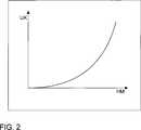
In
In
ZITATE ENTHALTEN IN DER BESCHREIBUNG QUOTES INCLUDE IN THE DESCRIPTION
Diese Liste der vom Anmelder aufgeführten Dokumente wurde automatisiert erzeugt und ist ausschließlich zur besseren Information des Lesers aufgenommen. Die Liste ist nicht Bestandteil der deutschen Patent- bzw. Gebrauchsmusteranmeldung. Das DPMA übernimmt keinerlei Haftung für etwaige Fehler oder Auslassungen.This list of the documents listed by the applicant has been generated automatically and is included solely for the better information of the reader. The list is not part of the German patent or utility model application. The DPMA assumes no liability for any errors or omissions.
Zitierte PatentliteraturCited patent literature
- DE 102009055939 A1[0002]DE 102009055939 A1[0002]
- US 2012/0150389 A1[0003]US 2012/0150389 A1[0003]
- DE 102007002972 A1[0003]DE 102007002972 A1[0003]
- DE 102011081697 A1[0003]DE 102011081697 A1[0003]
- DE 102009020826 A1[0003]DE 102009020826 A1[0003]
- DE 102009046118 A1[0003]DE 102009046118 A1[0003]
Claims (7)
Translated fromGermanPriority Applications (1)
| Application Number | Priority Date | Filing Date | Title |
|---|---|---|---|
| DE102012022457.5ADE102012022457B4 (en) | 2012-11-15 | 2012-11-15 | Method and device for controlling a steering of a vehicle |
Applications Claiming Priority (1)
| Application Number | Priority Date | Filing Date | Title |
|---|---|---|---|
| DE102012022457.5ADE102012022457B4 (en) | 2012-11-15 | 2012-11-15 | Method and device for controlling a steering of a vehicle |
Publications (2)
| Publication Number | Publication Date |
|---|---|
| DE102012022457A1true DE102012022457A1 (en) | 2014-05-15 |
| DE102012022457B4 DE102012022457B4 (en) | 2022-02-10 |
Family
ID=50555545
Family Applications (1)
| Application Number | Title | Priority Date | Filing Date |
|---|---|---|---|
| DE102012022457.5AActiveDE102012022457B4 (en) | 2012-11-15 | 2012-11-15 | Method and device for controlling a steering of a vehicle |
Country Status (1)
| Country | Link |
|---|---|
| DE (1) | DE102012022457B4 (en) |
Citations (10)
| Publication number | Priority date | Publication date | Assignee | Title |
|---|---|---|---|---|
| DE10146975A1 (en)* | 2000-09-25 | 2002-07-04 | Nsk Ltd | Control device for electric power steering |
| DE102005003178A1 (en)* | 2005-01-19 | 2006-07-27 | Volkswagen Ag | Transverse guidance assistance device for vehicle, has arithmetic and logic unit to determine reference lane that is determined from free lane, which is detected by sensor, and safety margin, where free lane is reduced by margin |
| EP1816053A1 (en)* | 2004-11-09 | 2007-08-08 | JTEKT Corporation | Electric power steering device |
| DE102007002972A1 (en) | 2006-03-03 | 2007-09-06 | Hitachi, Ltd. | Power Steering System |
| DE102007058078A1 (en)* | 2007-12-03 | 2009-06-04 | Audi Ag | Method and device for actively keeping a lane |
| DE102009020826A1 (en) | 2008-05-30 | 2010-01-07 | GM Global Technology Operations, Inc., Detroit | Reducing the effects of vibration in an electric power steering (EPS) system |
| DE102009046118A1 (en) | 2009-10-28 | 2011-05-05 | Zf Lenksysteme Gmbh | Method for operating an electrical power steering of vehicle, involves generating engine torque of electric motor over engine current which is calculated by engine controller |
| DE102009055939A1 (en) | 2009-11-26 | 2011-06-01 | Volkswagen Ag | Electromechanical steering and method for controlling electromechanical steering |
| DE102011081697A1 (en) | 2010-09-15 | 2012-03-15 | Gm Global Technology Operations Llc, ( N.D. Ges. D. Staates Delaware) | Methods, systems and devices for reducing steering wheel vibration in electric power steering systems |
| US20120150389A1 (en) | 2010-12-14 | 2012-06-14 | GM Global Technology Operations LLC | Electric power steering systems with improved road feel |
- 2012
- 2012-11-15DEDE102012022457.5Apatent/DE102012022457B4/enactiveActive
Patent Citations (10)
| Publication number | Priority date | Publication date | Assignee | Title |
|---|---|---|---|---|
| DE10146975A1 (en)* | 2000-09-25 | 2002-07-04 | Nsk Ltd | Control device for electric power steering |
| EP1816053A1 (en)* | 2004-11-09 | 2007-08-08 | JTEKT Corporation | Electric power steering device |
| DE102005003178A1 (en)* | 2005-01-19 | 2006-07-27 | Volkswagen Ag | Transverse guidance assistance device for vehicle, has arithmetic and logic unit to determine reference lane that is determined from free lane, which is detected by sensor, and safety margin, where free lane is reduced by margin |
| DE102007002972A1 (en) | 2006-03-03 | 2007-09-06 | Hitachi, Ltd. | Power Steering System |
| DE102007058078A1 (en)* | 2007-12-03 | 2009-06-04 | Audi Ag | Method and device for actively keeping a lane |
| DE102009020826A1 (en) | 2008-05-30 | 2010-01-07 | GM Global Technology Operations, Inc., Detroit | Reducing the effects of vibration in an electric power steering (EPS) system |
| DE102009046118A1 (en) | 2009-10-28 | 2011-05-05 | Zf Lenksysteme Gmbh | Method for operating an electrical power steering of vehicle, involves generating engine torque of electric motor over engine current which is calculated by engine controller |
| DE102009055939A1 (en) | 2009-11-26 | 2011-06-01 | Volkswagen Ag | Electromechanical steering and method for controlling electromechanical steering |
| DE102011081697A1 (en) | 2010-09-15 | 2012-03-15 | Gm Global Technology Operations Llc, ( N.D. Ges. D. Staates Delaware) | Methods, systems and devices for reducing steering wheel vibration in electric power steering systems |
| US20120150389A1 (en) | 2010-12-14 | 2012-06-14 | GM Global Technology Operations LLC | Electric power steering systems with improved road feel |
Also Published As
| Publication number | Publication date |
|---|---|
| DE102012022457B4 (en) | 2022-02-10 |
Similar Documents
| Publication | Publication Date | Title |
|---|---|---|
| DE102010025197B4 (en) | Method and device for filtering a setpoint signal | |
| WO2018167005A1 (en) | Estimating the rack force in a steer-by-wire system | |
| DE102019206980B4 (en) | Method and steering control device for determining a manipulated variable for setting a power steering torque in a vehicle steering system | |
| DE102010036655A1 (en) | Method for operating a steering system | |
| DE102014201394B4 (en) | Motorized Power Steering Friction Compensation Logic and Procedures | |
| DE102017212780B4 (en) | Process for generating haptic feedback | |
| DE102009045046A1 (en) | Method for operating an electronic power steering system of a motor vehicle | |
| DE102017223288A1 (en) | Method for operating a steer-by-wire steering system for a motor vehicle and steering system for a motor vehicle | |
| DE102017215593A1 (en) | Steer-by-wire system and method of operating a steer-by-wire system | |
| DE102007026189A1 (en) | Electromechanical steering mechanism for motor vehicle i.e. passenger car, has high pass filter for filtering difference signal, where high pass filtered difference signal is modulated with signal that represents additional steering moment | |
| DE102010031710A1 (en) | Method for operating electromechanical power steering of motor vehicle, involves applying supporting torque on steering gear of power steering by electrical machine in dependence of steering torque | |
| EP2058208A1 (en) | Method for controlling a superimposed steering system | |
| DE102012009568B3 (en) | Method for operating e.g. steer-by-wire steering system of passenger car, involves computing virtual driving speed value by computation device and transferring virtual driving speed value to superimposition controller at signal input | |
| DE102006018261A1 (en) | Procedure for a parking assistance | |
| DE102012102629A1 (en) | Method for controlling steering system of motor vehicle, involves controlling controller of steering force through one way path and feedback of steering force through return path, and integrating gain curves into one way and return paths | |
| DE102017215013B4 (en) | Steering control device and method for determining an actuating signal for power electronics of a steering device of a motor vehicle | |
| DE102012107595A1 (en) | Method for determination of target default value for motor torque of auxiliary or external power steering of motor car, involves determining target default value of servomotor based on rate of change of stable- and slow calculation values | |
| DE102020203212A1 (en) | Taking into account manual torque offsets in the vehicle steering system | |
| DE102012022457A1 (en) | Method for controlling steering element of motor vehicle, involves driving steering element by support force, and limiting gradient of support force when speed of vehicle is below preset speed | |
| DE102007006237A1 (en) | Method for operating a steering system in a motor vehicle | |
| DE102012022802B4 (en) | Method and device for controlling a steering of a vehicle | |
| DE102015211711A1 (en) | Method and device for operating a steering system | |
| DE102017213415B4 (en) | Method of operating a steering device | |
| DE102016100980B4 (en) | Method for operating a steering system of a motor vehicle | |
| DE102011016052A1 (en) | Method for determining target support moment in power steering system of motor car, involves assigning curve representing connection between hand and support moments, and determining target moment based on hand moment and vehicle velocity |
Legal Events
| Date | Code | Title | Description |
|---|---|---|---|
| R163 | Identified publications notified | ||
| R012 | Request for examination validly filed | ||
| R016 | Response to examination communication | ||
| R018 | Grant decision by examination section/examining division | ||
| R020 | Patent grant now final |