DE102012022039B4 - Modular laser radiation unit - Google Patents
Modular laser radiation unitDownload PDFInfo
- Publication number
- DE102012022039B4 DE102012022039B4DE102012022039.1ADE102012022039ADE102012022039B4DE 102012022039 B4DE102012022039 B4DE 102012022039B4DE 102012022039 ADE102012022039 ADE 102012022039ADE 102012022039 B4DE102012022039 B4DE 102012022039B4
- Authority
- DE
- Germany
- Prior art keywords
- laser
- laser beam
- radiation
- target
- module
- Prior art date
- Legal status (The legal status is an assumption and is not a legal conclusion. Google has not performed a legal analysis and makes no representation as to the accuracy of the status listed.)
- Active
Links
- 230000005855radiationEffects0.000titleclaimsabstractdescription129
- 238000005286illuminationMethods0.000claimsabstractdescription15
- 230000003287optical effectEffects0.000claimsabstractdescription13
- 230000001678irradiating effectEffects0.000claimsabstractdescription10
- 238000000034methodMethods0.000claimsdescription12
- 230000008685targetingEffects0.000claimsdescription4
- 239000013307optical fiberSubstances0.000claimsdescription2
- 239000000835fiberSubstances0.000description14
- 230000007246mechanismEffects0.000description4
- 230000004075alterationEffects0.000description3
- 238000003384imaging methodMethods0.000description3
- 239000011248coating agentSubstances0.000description2
- 238000000576coating methodMethods0.000description2
- 238000001514detection methodMethods0.000description2
- 238000010586diagramMethods0.000description2
- 239000000463materialSubstances0.000description2
- 230000006978adaptationEffects0.000description1
- 230000001427coherent effectEffects0.000description1
- 238000010276constructionMethods0.000description1
- 230000008878couplingEffects0.000description1
- 238000010168coupling processMethods0.000description1
- 238000005859coupling reactionMethods0.000description1
- 230000001419dependent effectEffects0.000description1
- 230000003760hair shineEffects0.000description1
- 238000003909pattern recognitionMethods0.000description1
- 230000008569processEffects0.000description1
Images


Classifications
- G—PHYSICS
- G01—MEASURING; TESTING
- G01S—RADIO DIRECTION-FINDING; RADIO NAVIGATION; DETERMINING DISTANCE OR VELOCITY BY USE OF RADIO WAVES; LOCATING OR PRESENCE-DETECTING BY USE OF THE REFLECTION OR RERADIATION OF RADIO WAVES; ANALOGOUS ARRANGEMENTS USING OTHER WAVES
- G01S7/00—Details of systems according to groups G01S13/00, G01S15/00, G01S17/00
- G01S7/48—Details of systems according to groups G01S13/00, G01S15/00, G01S17/00 of systems according to group G01S17/00
- G01S7/481—Constructional features, e.g. arrangements of optical elements
- F—MECHANICAL ENGINEERING; LIGHTING; HEATING; WEAPONS; BLASTING
- F41—WEAPONS
- F41G—WEAPON SIGHTS; AIMING
- F41G1/00—Sighting devices
- F41G1/32—Night sights, e.g. luminescent
- F41G1/34—Night sights, e.g. luminescent combined with light source, e.g. spot light
- F41G1/36—Night sights, e.g. luminescent combined with light source, e.g. spot light with infrared light source
- F—MECHANICAL ENGINEERING; LIGHTING; HEATING; WEAPONS; BLASTING
- F41—WEAPONS
- F41H—ARMOUR; ARMOURED TURRETS; ARMOURED OR ARMED VEHICLES; MEANS OF ATTACK OR DEFENCE, e.g. CAMOUFLAGE, IN GENERAL
- F41H13/00—Means of attack or defence not otherwise provided for
- F41H13/0043—Directed energy weapons, i.e. devices that direct a beam of high energy content toward a target for incapacitating or destroying the target
- F41H13/005—Directed energy weapons, i.e. devices that direct a beam of high energy content toward a target for incapacitating or destroying the target the high-energy beam being a laser beam
- G—PHYSICS
- G01—MEASURING; TESTING
- G01S—RADIO DIRECTION-FINDING; RADIO NAVIGATION; DETERMINING DISTANCE OR VELOCITY BY USE OF RADIO WAVES; LOCATING OR PRESENCE-DETECTING BY USE OF THE REFLECTION OR RERADIATION OF RADIO WAVES; ANALOGOUS ARRANGEMENTS USING OTHER WAVES
- G01S17/00—Systems using the reflection or reradiation of electromagnetic waves other than radio waves, e.g. lidar systems
- G01S17/66—Tracking systems using electromagnetic waves other than radio waves
Landscapes
- Engineering & Computer Science (AREA)
- Physics & Mathematics (AREA)
- Radar, Positioning & Navigation (AREA)
- Remote Sensing (AREA)
- Computer Networks & Wireless Communication (AREA)
- General Physics & Mathematics (AREA)
- Electromagnetism (AREA)
- Optics & Photonics (AREA)
- General Engineering & Computer Science (AREA)
- Laser Beam Processing (AREA)
- Studio Devices (AREA)
Abstract
Translated fromGermanDescription
Translated fromGermanGEBIET DER ERFINDUNGFIELD OF THE INVENTION
Die Erfindung betrifft eine Laserbestrahlungseinheit sowie ein Verfahren zum Bestrahlen eines Zielobjekts mit Laserstrahlung.The invention relates to a laser radiation unit and a method for irradiating a target object with laser radiation.
HINTERGRUND DER ERFINDUNGBACKGROUND OF THE INVENTION
Hochleistungslaser werden sowohl im militärischen Bereich als auch im zivilen Bereich zum Bearbeiten von Zielobjekten eingesetzt. Beispielsweise kann mit einem Hochleistungsinfrarotlaser ein entferntes Zielobjekt, wie etwa Munition oder ein gegnerisches Ziel, bestrahlt werden, um das Zielobjekt zu beschädigen oder zu zerstören.High-power lasers are used in the military as well as in the civilian area to process target objects. For example, a high power infrared laser can be used to irradiate a distant target, such as ammunition or an enemy target, to damage or destroy the target.
Eine entsprechende Laserbestrahlungseinheit muss in der Regel dazu das Zielobjekt erfassen, den Hochleistungsinfrarotlaserstrahl erzeugen und auf das Zielobjekt ausrichten.A corresponding laser irradiation unit usually has to detect the target object, generate the high-power infrared laser beam and align it with the target object.
Aus der
Aus der
Außerdem kennt man aus der
ZUSAMMENFASSUNG DER ERFINDUNGSUMMARY OF THE INVENTION
Es ist Aufgabe der Erfindung, eine einfach zu wartende und einfach zu bedienenden Laserbestrahlungseinheit bereitzustellen.It is an object of the invention to provide an easy-to-maintain and easy-to-use laser irradiation unit.
Diese Aufgabe wird durch den Gegenstand der unabhängigen Ansprüche gelöst. Weitere Ausführungsformen der Erfindung ergeben sich aus den abhängigen Ansprüchen und aus der folgenden Beschreibung.This object is achieved by the subject matter of the independent claims. Further embodiments of the invention result from the dependent claims and from the following description.
Ein erster Aspekt der Erfindung betrifft eine Laserbestrahlungseinheit zum Bestrahlen eines Zielobjekts mit Hochleistungslaserstrahlung. Die Laserbestrahlungseinheit bzw. das Laserbestrahlungsgerät kann beispielsweise an ein Fahrzeug oder Flugzeug montiert sein.A first aspect of the invention relates to a laser irradiation unit for irradiating a target object with high-power laser radiation. The laser radiation unit or the laser radiation device can, for example, be mounted on a vehicle or aircraft.
Dabei beruht die Erfindung auf an sich bekannten Laserbestrahlungseinheiten mit mehreren starr miteinander verbundenen Laserstrahlmodulen, die dazu ausgeführt sind, Laserstrahlung abzugeben; und eine Richteinheit, zum Ausrichten der Laserstrahlmodule auf das Zielobjekt; wobei jedes der Laserstrahlmodule eine Optik umfasst, die dazu ausgeführt ist, Laserstrahlung auf einen Zielpunkt des Zielobjekts auszurichten und/oder zu fokussieren.The invention is based on known laser radiation units with a plurality of rigidly interconnected laser beam modules which are designed to emit laser radiation; and a straightening unit for aligning the laser beam modules with the target object; wherein each of the laser beam modules comprises an optical system which is designed to align and / or focus laser radiation onto a target point of the target object.
Die Laserbestrahlungseinheit umfasst erfindungsgemäß mehrere erste (Hochleistungs-, Bestrahlungs- und/oder Bearbeitungs-)Laserstrahlmodule, die dazu ausgeführt sind, erste Laserstrahlung einer ersten Wellenlänge abzugeben, und ein zweites (Zielmarkierungs-)Laserstrahlmodul, das dazu ausgeführt ist, zweite Laserstrahlung einer zweiten Wellenlänge abzugeben und auf den Zielpunkt zu fokussieren. Dabei sind die ersten Laserstrahlmodule dazu ausgeführt, die zweite Laserstrahlung mit einem Detektor zu detektieren und können eine verstellbare Optik aufweisen, die die eingehende zweite Laserstrahlung auf den Detektor ausrichtet und gleichzeitig die ausgehende erste Laserstrahlung auf den Zielpunkt ausrichtet. Mit anderen Worten kann eine auf den Zielpunkt gerichtete zweite Laserstrahlung aus einem zweiten Lasermodul dazu verwendet werden, die ersten Laserstrahlmodule auf den Zielpunkt auszurichten und/oder zu fokussieren.According to the invention, the laser radiation unit comprises a plurality of first (high-power, radiation and / or processing) laser beam modules which are designed to emit first laser radiation of a first wavelength, and a second (target marking) laser beam module which is designed to emit second laser radiation of a second Emit wavelength and focus on the target point. The first laser beam modules are designed to detect the second laser radiation with a detector and can have adjustable optics that align the incoming second laser radiation to the detector and at the same time align the outgoing first laser radiation to the target point. In other words, a second laser radiation directed at the target point from a second laser module can be used to align and / or focus the first laser beam modules on the target point.
Beispielsweise können die Laserstrahlmodule jeweils ein gleichartig aufgebautes (etwa rohrförmiges) Gehäuse aufweisen. Die Gehäuse können mittels eines gemeinsamen Rahmens miteinander verbunden sein. Dieser Rahmen kann auch weitere Module, wie etwa ein Kameramodul und/oder ein Beleuchtungsmodul, aufnehmen. Die Module können mit dem gemeinsamen Rahmen gemeinsam auf ein Ziel (grob) ausgerichtet werden.For example, the laser beam modules can each have an identically constructed (approximately tubular) housing. The housings can be connected to one another by means of a common frame. This frame can also accommodate other modules, such as a camera module and / or a lighting module. The modules can can be roughly aligned with the common framework.
Die Laserbestrahlungseinheit kann mehrere, möglichst gleichartige aufgebaute Module aufweisen, die eine punktgenaue Materialbearbeitung mit einer hohen Strahlleistung im Bereich von einigen zehn bis hundert Kilowatt auf große Entfernungen im km-Bereich ermöglichen.The laser irradiation unit can have a plurality of modules of the same type, which are as similar as possible and which enable precise material processing with a high beam power in the range from a few tens to a hundred kilowatts over long distances in the km range.
Einsatzmöglichkeiten der Laserbestrahlungseinheit sind beispielsweise beim Abbau von Kernkraftwerken oder der Beseitigung von Munition. Ebenfalls ist ein militärischer Einsatz möglich.Possible uses of the laser radiation unit are, for example, in the dismantling of nuclear power plants or the removal of ammunition. Military use is also possible.
Durch die Modularisierung der Laserbestrahlungseinheit mittels einer Mehrzahl von Modulen ist eine einfache Anpassung an die jeweiligen Anforderungen möglich. Die jeweils erforderliche Laserleistung lässt sich zum Beispiel einfach durch die Anzahl der Laserstrahlmodule anpassen.The modularization of the laser irradiation unit by means of a plurality of modules enables simple adaptation to the respective requirements. The laser power required in each case can be easily adjusted, for example, by the number of laser beam modules.
Gemäß einer Ausführungsform der Erfindung umfasst die Optik eines Laserstrahlmoduls oder aller Laserstrahlmodule einen Detektor zum Erfassen von eingehender Strahlung. Die Laserbestrahlungseinheit kann dahingehend noch weiter modularisiert sein, dass jedes einzelne Laserstrahlmodul einen Detektor umfasst, der dazu ausgeführt ist, eingehende Strahlung (beispielsweise von einem Zielpunkt des Zielobjekts) zu erfassen, die dazu verwendet wird, die Optik derart einzustellen, dass sie auf einen Zielpunkt eingestellt, d.h. ausgerichtet und/oder fokussiert ist.According to one embodiment of the invention, the optics of a laser beam module or all laser beam modules comprise a detector for detecting incoming radiation. The laser irradiation unit can be further modularized in that each individual laser beam module comprises a detector which is designed to detect incoming radiation (for example from a target point of the target object), which is used to adjust the optics in such a way that they point to a target point set, ie is aligned and / or focused.
Gemäß einer Ausführungsform der Erfindung weist die Optik eines Laserstrahlmoduls ein verstellbares Teleskop auf, das dazu ausgeführt ist, eine ausgehende Laserstrahlung auf den Zielpunkt zu fokussieren und eingehende Strahlung auf einen Detektor zu fokussieren.According to one embodiment of the invention, the optics of a laser beam module have an adjustable telescope, which is designed to focus an outgoing laser radiation onto the target point and to focus incoming radiation onto a detector.
Gemäß einer Ausführungsform der Erfindung weist die Optik eines Laserstrahlmoduls einen verstellbaren Umlenkspiegel auf, der dazu ausgeführt ist, ausgehende Laserstrahlung auf den Zielpunkt auszurichten und eingehende Strahlung auf einen Detektor auszurichten.According to one embodiment of the invention, the optics of a laser beam module have an adjustable deflecting mirror, which is designed to align outgoing laser radiation with the target point and to direct incoming radiation to a detector.
Es ist zu verstehen, dass ein Bestrahlungs- bzw. Bearbeitungslasermodul ausgehende Hochleistungs-Laserstrahlung auf das Zielobjekt strahlen kann und gleichzeitig eingehende Zielmarkierungslaserstrahlung erfassen kann. Analog kann ein Zielmarkierungslasermodul ausgehende Zielmarkierungslaserstrahlung auf das Zielobjekt strahlen und gleichzeitig eingehende Beleuchtungsstrahlung erfassen.It is to be understood that an irradiation or processing laser module can radiate outgoing high-power laser radiation onto the target object and at the same time can detect incoming target marking laser radiation. Analogously, a target marking laser module can radiate outgoing target marking laser radiation onto the target object and simultaneously detect incoming illuminating radiation.
Der Umlenkspiegel kann mit einem Aktuator, beispielsweise einem Elektro- oder Piezomotor, in zwei Richtungen geschwenkt werden, um auf diese Weise Strahlung vom Zielpunkt (zum Einstellen der Optik) auf den Detektor zu richten und um Strahlung (zum Bestrahlen des Zielpunkts) auf den Zielpunkt auszurichten.The deflection mirror can be pivoted in two directions with an actuator, for example an electric or piezomotor, in order to direct radiation from the target point (for setting the optics) onto the detector and for radiation (for irradiating the target point) to the target point align.
Gemäß einer Ausführungsform der Erfindung weist die Optik eines Laserstrahlmoduls einen halbdurchlässigen Spiegel auf, der ausgehende Laserstrahlung reflektiert und für eingehende Strahlung durchlässig ist. Auf diese Weise kann die Strahlung für den Detektor und die Strahlung, die das Laserstrahlmodul verlassen soll, voneinander getrennt werden. Beispielsweise reflektiert der halbdurchlässige Spiegel nur im Wellenlängenbereich der ausgehenden Strahlung, ist aber in anderen Wellenlängenbereichen durchlässig.According to one embodiment of the invention, the optics of a laser beam module have a semi-transparent mirror which reflects outgoing laser radiation and is transparent to incoming radiation. In this way, the radiation for the detector and the radiation which is to leave the laser beam module can be separated from one another. For example, the semi-transparent mirror reflects only in the wavelength range of the outgoing radiation, but is transparent in other wavelength ranges.
Gemäß einer Ausführungsform der Erfindung umfasst ein Laserstrahlmodul eine Steuerung, die dazu ausgeführt ist, einen Aktuator eines verstellbaren Umlenkspiegels und/oder einen Aktuator eines verstellbaren Teleskops anzusteuern. Jedes Laserstrahlmodul kann eine eigene Steuerung aufweisen, die beispielsweise in das Gehäuse des Laserstrahlmoduls verbaut ist, wodurch die Laserbestrahlungseinheit weiter modularisiert werden kann. Die Laserstrahlmodule können mit der Steuerung ihre Optik selbstständig einstellen.According to one embodiment of the invention, a laser beam module comprises a controller which is designed to control an actuator of an adjustable deflecting mirror and / or an actuator of an adjustable telescope. Each laser beam module can have its own control, which is installed, for example, in the housing of the laser beam module, as a result of which the laser radiation unit can be further modularized. The laser beam modules can adjust their optics independently with the control.
Gemäß einer Ausführungsform der Erfindung umfasst die Laserbestrahlungseinheit weiter mehrere Laserquellen, die dazu ausgeführt sind, Laserstrahlung zu erzeugen und die jeweils mit einer optischen Faser mit einem Laserstrahlmodul verbunden sind. Die Richteinheit kann dazu ausgeführt sein, die Laserstrahlmodule unabhängig von den Laserquellen zu bewegen. Die Laserquellen können Faserlaser sein, die beispielsweise ein Infrarotlicht für die Bestrahlungslaserstrahlmodule und/oder ein Licht im sichtbaren Bereich für ein Zielmarkierungslaserstrahlmodul erzeugen können.According to one embodiment of the invention, the laser irradiation unit further comprises a plurality of laser sources which are designed to generate laser radiation and which are each connected to an optical fiber with a laser beam module. The straightening unit can be designed to move the laser beam modules independently of the laser sources. The laser sources can be fiber lasers which can generate, for example, infrared light for the irradiation laser beam modules and / or light in the visible range for a target marking laser beam module.
Gemäß einer Ausführungsform der Erfindung ist die erste Laserstrahlung dazu geeignet, das Zielobjekt zu bearbeiten. Beispielsweise kann die erste Laserstrahlung von einem ersten Laserstrahlmodul zwischen 1 Kilowatt und 10 Kilowatt Leistung aufweisen.According to one embodiment of the invention, the first laser radiation is suitable for processing the target object. For example, the first laser radiation from a first laser beam module can have an output of between 1 kilowatt and 10 kilowatts.
Gemäß der Erfindung ist das zweite Laserstrahlmodul dazu ausgeführt, eine Beleuchtungsstrahlung mit einem Detektor zu detektieren. Mit anderen Worten kann eine auf den Zielpunkt gerichtete Beleuchtungsstrahlung aus einem Beleuchtungsmodul dazu verwendet werden, das zweite Laserstrahlmodul auf den Zielpunkt auszurichten.According to the invention, the second laser beam module is designed to detect illuminating radiation with a detector. In other words, an illuminating radiation directed at the target point from an illuminating module can be used to align the second laser beam module with the target point.
Das zweite Laserstrahlmoduleine weist erfindungsgemäß eine verstellbare Optik auf, die die eingehende Beleuchtungsstrahlung auf den Detektor ausrichtet und gleichzeitig die ausgehende zweite Laserstrahlung auf den Zielpunkt ausrichtet und/oder fokussiert.According to the invention, the second laser beam module has adjustable optics that direct the incoming illuminating radiation onto the detector aligns and at the same time aligns and / or focuses the outgoing second laser radiation to the target point.
Gemäß einer Ausführungsform der Erfindung ist die Optik der Laserstrahlmodule gleich aufgebaut. Sowohl die Bearbeitungslaserstrahlmodule als auch die Zielmarkierungslaserstrahlmodule können eine Optik mit einem verstellbaren Teleskop, einem verstellbaren Umlenkspiegel und/oder einem halbdurchlässigen Spiegel aufweisen, die ähnliche oder baugleiche Komponenten umfassen.According to one embodiment of the invention, the optics of the laser beam modules have the same structure. Both the processing laser beam modules and the target marking laser beam modules can have optics with an adjustable telescope, an adjustable deflecting mirror and / or a semitransparent mirror which comprise similar or structurally identical components.
Gemäß einer Ausführungsform der Erfindung umfasst die Laserbestrahlungseinheit weiter ein mit den Laserstrahlmodulen starr verbundenes Zielbeleuchtungsstrahlmodul, das eine Beleuchtungsquelle zum Erzeugen einer Beleuchtungsstrahlung und ein Teleskop zum Fokussieren der Beleuchtungsstrahlung umfasst. Wenn das Umgebungslicht nicht ausreicht, kann das Zielbeleuchtungsstrahlmodul, das beispielsweise eine Strahlung im sichtbaren Bereich erzeugt, dazu verwendet werden, das Zielobjekt auszuleuchten.According to one embodiment of the invention, the laser irradiation unit further comprises a target illuminating beam module rigidly connected to the laser beam modules, which comprises an illuminating source for generating illuminating radiation and a telescope for focusing the illuminating radiation. If the ambient light is insufficient, the target illumination beam module, which for example generates radiation in the visible range, can be used to illuminate the target object.
Gemäß einer Ausführungsform der Erfindung umfasst die Laserbestrahlungseinheit weiter ein mit den Laserstrahlmodulen starr verbundenes Kameramodul, das eine Kamera und ein Teleskop umfasst. Mit dem Kameramodul kann ein Bild von dem Bereich erfasst werden, auf den die Laserstrahlmodule gerade gerichtet sind. Das Bild kann auf einem Bildschirm angezeigt werden, so dass eine Person das Kameramodul zusammen mit den anderen Modulen auf das Zielobjekt ausrichten kann.According to one embodiment of the invention, the laser irradiation unit further comprises a camera module which is rigidly connected to the laser beam modules and which comprises a camera and a telescope. The camera module can be used to capture an image of the area to which the laser beam modules are directed. The image can be displayed on a screen so that one person can align the camera module with the other modules to the target object.
Gemäß einer Ausführungsform der Erfindung weisen die Laserstrahlmodule (und/oder das Zielbeleuchtungsmodul und/oder das Kameramodul) jeweils ein rohrförmiges Gehäuse auf. Die rohrförmigen Gehäuse können (beispielsweise mit einem gemeinsamen Rahmen) zu einem Bündel zusammengefasst sein, das von der Richteinheit bewegbar ist. Dazu kann die Richteinheit einen oder mehrere Aktuatoren aufweisen, die das Bündel bewegen können.According to one embodiment of the invention, the laser beam modules (and / or the target illumination module and / or the camera module) each have a tubular housing. The tubular housing can be combined (for example with a common frame) into a bundle that can be moved by the straightening unit. For this purpose, the straightening unit can have one or more actuators which can move the bundle.
Ein erster Aspekt der Erfindung betrifft ein Verfahren zum Bestrahlen eines Zielobjekts mit Hochleistungslaserstrahlung. Es ist zu verstehen, dass Merkmale des Verfahrens Merkmale der Laserbestrahlungseinheit sein können und umgekehrt.A first aspect of the invention relates to a method for irradiating a target object with high-power laser radiation. It is to be understood that features of the method can be features of the laser irradiation unit and vice versa.
Gemäß einer Ausführungsform der Erfindung umfasst das Verfahren die Schritte von: Erfassen eines Zielpunkts eines Zielobjekts mit einem Detektor eines Zielmarkierungslaserstrahlmoduls, wobei der Detektor dazu ausgeführt ist, eine Wellenlänge zu erfassen, die sich von einer Wellenlänge einer Zielerfassungslaserstrahlung unterscheidet; Ausrichten eines Zielmarkierungslaserstrahls auf den Zielpunkt mit dem Zielmarkierungslaserstrahlmodul; Verstellen einer Optik eines Bearbeitungslaserstrahlmoduls, so dass Zielmarkierungslaserstrahlung auf einen Detektor des Bearbeitungslaserstrahlmoduls gerichtet wird, wobei der Detektor dazu ausgeführt ist, eine Wellenlänge der Zielerfassungslaserstrahlung zu erfassen; und Bestrahlen des Zielpunkts mit einem Bearbeitungslaserstrahl, wobei der Bearbeitungslaserstrahl von der Optik des Bearbeitungslaserstrahlmoduls ausgerichtet (und fokussiert) wird, die auch die Zielmarkierungslaserstrahlung auf den Detektor des Bearbeitungslaserstrahlmoduls ausrichtet (und fokussiert).According to one embodiment of the invention, the method comprises the steps of: detecting a target point of a target object with a detector of a target marking laser beam module, the detector being designed to detect a wavelength that differs from a wavelength of a target detection laser radiation; Aligning a target laser beam with the target laser beam module; Adjusting an optical system of a processing laser beam module so that target marking laser radiation is directed onto a detector of the processing laser beam module, the detector being designed to detect a wavelength of the target detection laser radiation; and irradiating the target point with a processing laser beam, wherein the processing laser beam is aligned (and focused) by the optics of the processing laser beam module, which also aligns (and focuses) the target marking laser radiation with the detector of the processing laser beam module.
Beispielsweise kann Beleuchtungslicht oder Beleuchtungslaserstrahlung, das oder die beispielsweise von einem Beleuchtungsmodul stammen kann, mit dem Zielmarkierungslasermodul erfasst werden. Dies kann dadurch geschehen, dass eine Optik des Zielmarkierungslasermoduls derart eingestellt bzw. verstellt wird, dass die Beleuchtungslaserstrahlung auf einen Detektor (beispielsweise eine Kamera) gerichtet wird, so dass der Zielpunkt auf das Zentrum der Kamera abgebildet wird. Die gleiche Optik (die beispielsweise einen verstellbaren Umlenkspiegel zum Ausrichten der Beleuchtungslaserstrahlung und/oder ein verstellbares Teleskop zum Fokussieren des Zielpunkts auf den Detektor umfassen kann) kann dann dazu verwendet werden, einen Zielmarkierungslaserstrahl auf den Zielpunkt auszurichten und zu fokussieren.For example, illuminating light or illuminating laser radiation, which, for example, can originate from an illuminating module, can be detected with the target marking laser module. This can be done in that an optical system of the target marking laser module is adjusted or adjusted such that the illuminating laser radiation is directed onto a detector (for example a camera), so that the target point is imaged on the center of the camera. The same optics (which may include, for example, an adjustable deflecting mirror for aligning the illumination laser radiation and / or an adjustable telescope for focusing the target point on the detector) can then be used to align and focus a target marking laser beam on the target point.
Das Bestrahlungslasermodul erfasst mit einer Optik, die eine identische oder baugleiche Optik wie die des Zielmarkierungslaserstrahlmoduls sein kann, die Zielmarkierungslaserstrahlung von dem Zielpunkt. Analog wie das Zielmarkierungslaserstrahlmodul stellt das Bestrahlungslasermodul seine Optik so ein, dass der Zielpunkt auf einen Detektor (beispielsweise einen Vierquadrantendetektor) ausgerichtet und fokussiert ist. Mit der gleichen Optik wird dann der Bestrahlungslaser auf den Zielpunkt gerichtet und fokussiert und mit Bestrahlungslaserstrahlung bearbeitet.The irradiation laser module detects the target marking laser radiation from the target point with an optical system, which can be an identical or identical optical system as that of the target marking laser beam module. Analogous to the target marking laser beam module, the radiation laser module adjusts its optics in such a way that the target point is aligned and focused on a detector (for example a four-quadrant detector). With the same optics, the radiation laser is then aimed and focused at the target point and processed with radiation laser radiation.
Die eben genannten Verfahrensschritte können zum Feineinstellen der Laserstrahlen auf einen Zielpunkt des Zielobjekts verwendet werden.The method steps just mentioned can be used to fine-tune the laser beams to a target point of the target object.
Zum Grobeinstellen bzw. Grobausrichten der Laserbestrahlungseinheit können die Lasermodule gemeinsam auf das Zielobjekt ausgerichtet werden, indem sie beispielweise mit einer Richteinheit, die um zwei Achsen schwenkbar ist, gemeinsam bewegt werden.For rough adjustment or rough alignment of the laser irradiation unit, the laser modules can be aligned together on the target object, for example by moving them together with a straightening unit that can be pivoted about two axes.
Im Folgenden werden Ausführungsbeispiele der Erfindung mit Bezug auf die beiliegenden Figuren detailliert beschrieben.Exemplary embodiments of the invention are described in detail below with reference to the accompanying figures.
Figurenliste Figure list
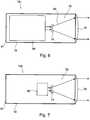
1 zeigt schematisch eine Frontansicht einer Laserbestrahlungseinheit gemäß einer Ausführungsform der Erfindung.1 schematically shows a front view of a laser irradiation unit according to an embodiment of the invention.2 zeigt schematisch eine Seitenansicht der Laserbestrahlungseinheit aus der1 .2nd shows schematically a side view of the laser irradiation unit from the1 .3 zeigt ein Flussdiagramm für ein Verfahren zum Bestrahlen eines Zielobjekts mit Hochleistungslaserlicht gemäß einer Ausführungsform der Erfindung.3rd FIG. 10 shows a flow diagram for a method for irradiating a target object with high-power laser light according to an embodiment of the invention.4 zeigt eine schematische Querschnittsansicht eines Hochleistungslaser-Strahlmoduls für eine Laserbestrahlungseinheit gemäß einer Ausführungsform der Erfindung.4th shows a schematic cross-sectional view of a high-power laser beam module for a laser irradiation unit according to an embodiment of the invention.5 zeigt eine schematische Querschnittsansicht eines Hochleistungslaser-Strahlmoduls für eine Laserbestrahlungseinheit gemäß einer Ausführungsform der Erfindung.5 shows a schematic cross-sectional view of a high-power laser beam module for a laser irradiation unit according to an embodiment of the invention.6 zeigt eine schematische Querschnittsansicht eines ZielmarkierungslaserStrahlmoduls für eine Laserbestrahlungseinheit gemäß einer Ausführungsform der Erfindung.6 shows a schematic cross-sectional view of a target marking laser beam module for a laser irradiation unit according to an embodiment of the invention.7 zeigt eine schematische Querschnittsansicht eines Kameramoduls für eine Laserbestrahlungseinheit gemäß einer Ausführungsform der Erfindung.7 shows a schematic cross-sectional view of a camera module for a laser irradiation unit according to an embodiment of the invention.
Grundsätzlich sind identische oder ähnliche Teile mit den gleichen Bezugszeichen versehen.In principle, identical or similar parts are provided with the same reference symbols.
DETAILLIERTE BESCHREIBUNG VON AUSFÜHRUNGSBEISPIELENDETAILED DESCRIPTION OF EMBODIMENTS
Die Module
Die Module
Die Achsparallelität der Module
Die Bündelungseinheit
Die Richteinheit
Die beiden Aktuatoren
Das Laserlicht für die Hochleistungslaser-Strahlmodule
Das Lasermodul
Weiter kann die Laserbestrahlungseinheit
Im Schritt
Im Schritt
Im Schritt
Im Schritt
Im Schritt
Im Schritt
Die Schritte
Die
Das Strahlmodul
Das Strahlmodul
Das eine Ende des Gehäuses umfasst einen Deckel
Im Inneren des Gehäuses
Der divergente Strahl aus der Ausgangsfaser
Mit dem aus den Linsen
Der Durchmesser der Linse
Mit dem Umlenkspiegel
Um die Stellung des Umlenkspiegels
Die Laserstrahlung
Die Laserstrahlung
Die Steuerung
Aus der Laufzeit des Empfangssignals des Detektor
Die
Der Faserstecker
Der Umlenkspiegel
Weiter weist das Strahlmodul
Das von der Kamera
Durch das Auswählen des Zielpunkts wird der Umlenkspiegel
Die
Das Strahlmodul
Die Wellenlänge der Strahlung
Die
Das Kameramodul
Analog dem Strahlmodul
Ergänzend ist darauf hinzuweisen, dass „umfassend“ keine anderen Elemente oder Schritte ausschließt und „eine“ oder „ein“ keine Vielzahl ausschließt. Ferner sei darauf hingewiesen, dass Merkmale oder Schritte, die mit Verweis auf eines der obigen Ausführungsbeispiele beschrieben worden sind, auch in Kombination mit anderen Merkmalen oder Schritten anderer oben beschriebener Ausführungsbeispiele verwendet werden können. Bezugszeichen in den Ansprüchen sind nicht als Einschränkung anzusehen.In addition, it should be pointed out that "comprehensive" does not exclude other elements or steps and "one" or "one" does not exclude a large number. It should also be pointed out that features or steps that have been described with reference to one of the above exemplary embodiments can also be used in combination with other features or steps of other exemplary embodiments described above. Reference signs in the claims are not to be viewed as a restriction.
Claims (12)
Translated fromGermanPriority Applications (7)
| Application Number | Priority Date | Filing Date | Title |
|---|---|---|---|
| DE102012022039.1ADE102012022039B4 (en) | 2012-11-09 | 2012-11-09 | Modular laser radiation unit |
| PCT/DE2013/000650WO2014071906A1 (en) | 2012-11-09 | 2013-11-06 | Modular laser irradiation unit |
| SG11201502806QASG11201502806QA (en) | 2012-11-09 | 2013-11-06 | Modular laser irradiation unit |
| ES13817850TES2751411T3 (en) | 2012-11-09 | 2013-11-06 | Modular laser irradiation unit |
| US14/441,625US10180492B2 (en) | 2012-11-09 | 2013-11-06 | Modular laser irradiation unit |
| EP13817850.4AEP2917681B1 (en) | 2012-11-09 | 2013-11-06 | Modular laser irradiation unit |
| IL238521AIL238521B (en) | 2012-11-09 | 2015-04-29 | Modular laser irradiation unit |
Applications Claiming Priority (1)
| Application Number | Priority Date | Filing Date | Title |
|---|---|---|---|
| DE102012022039.1ADE102012022039B4 (en) | 2012-11-09 | 2012-11-09 | Modular laser radiation unit |
Publications (2)
| Publication Number | Publication Date |
|---|---|
| DE102012022039A1 DE102012022039A1 (en) | 2014-05-15 |
| DE102012022039B4true DE102012022039B4 (en) | 2020-03-26 |
Family
ID=49918334
Family Applications (1)
| Application Number | Title | Priority Date | Filing Date |
|---|---|---|---|
| DE102012022039.1AActiveDE102012022039B4 (en) | 2012-11-09 | 2012-11-09 | Modular laser radiation unit |
Country Status (7)
| Country | Link |
|---|---|
| US (1) | US10180492B2 (en) |
| EP (1) | EP2917681B1 (en) |
| DE (1) | DE102012022039B4 (en) |
| ES (1) | ES2751411T3 (en) |
| IL (1) | IL238521B (en) |
| SG (1) | SG11201502806QA (en) |
| WO (1) | WO2014071906A1 (en) |
Families Citing this family (20)
| Publication number | Priority date | Publication date | Assignee | Title |
|---|---|---|---|---|
| IL234036B (en)* | 2014-08-10 | 2018-11-29 | Rafael Advanced Defense Systems Ltd | Directed energy weapon |
| CN110045383B (en)* | 2016-11-30 | 2023-03-14 | 中国人民解放军陆军炮兵防空兵学院 | Laser active rejection system |
| DE102017104662B4 (en)* | 2017-03-06 | 2025-03-13 | Rheinmetall Waffe Munition Gmbh | Weapon system with at least two HEL effectors |
| DE102018100891A1 (en) | 2018-01-16 | 2019-07-18 | Rheinmetall Waffe Munition Gmbh | High power laser, in particular laser weapon |
| US10274979B1 (en) | 2018-05-22 | 2019-04-30 | Capital One Services, Llc | Preventing image or video capture of input data provided to a transaction device |
| JP7292315B2 (en) | 2018-06-06 | 2023-06-16 | マジック アイ インコーポレイテッド | Distance measurement using high density projection pattern |
| EP3581876A1 (en)* | 2018-06-13 | 2019-12-18 | BAE SYSTEMS plc | Apparatus for a directed-energy weapon |
| AU2019285841B2 (en) | 2018-06-13 | 2024-07-18 | Bae Systems Plc | Apparatus for a directed-energy weapon |
| AU2019285839B2 (en) | 2018-06-13 | 2024-07-04 | Bae Systems Plc | Apparatus for a directed-energy weapon |
| EP3581877A1 (en)* | 2018-06-13 | 2019-12-18 | BAE SYSTEMS plc | Apparatus for a directed-energy weapon |
| AU2019285840B2 (en)* | 2018-06-13 | 2024-08-08 | Bae Systems Plc | Apparatus for a directed-energy weapon |
| DE102018126833A1 (en)* | 2018-10-26 | 2020-04-30 | Rheinmetall Waffe Munition Gmbh | Radiation weapon and method for representing the location of a radiation weapon meeting point |
| US10438010B1 (en) | 2018-12-19 | 2019-10-08 | Capital One Services, Llc | Obfuscation of input data provided to a transaction device |
| US11483503B2 (en) | 2019-01-20 | 2022-10-25 | Magik Eye Inc. | Three-dimensional sensor including bandpass filter having multiple passbands |
| GB2590956B (en)* | 2020-01-09 | 2022-06-29 | Thales Holdings Uk Plc | Guidance head and method |
| WO2022015900A1 (en)* | 2020-07-14 | 2022-01-20 | Mccain Steven Quinn | Remote pointing device |
| CN112461052A (en)* | 2020-11-26 | 2021-03-09 | 中国航空制造技术研究院 | Multi-interference-waveband laser directional infrared counterrotating tower |
| JP7566621B2 (en) | 2020-12-24 | 2024-10-15 | 三菱重工業株式会社 | Laser Tracking Device |
| US20220382121A1 (en)* | 2021-05-27 | 2022-12-01 | Lawrence Livermore National Security, Llc | System and method for coherent aperture of steered emitters |
| FR3128523B1 (en)* | 2021-10-26 | 2023-10-27 | Arquus | Aiming and defense system comprising a cupola and a laser system and motor vehicle comprising such an aiming and defense system |
Citations (8)
| Publication number | Priority date | Publication date | Assignee | Title |
|---|---|---|---|---|
| US3541468A (en)* | 1966-01-03 | 1970-11-17 | Martin Marietta Corp | Pulsed laser array |
| DE3202432A1 (en)* | 1982-01-26 | 1983-08-04 | Messerschmitt-Bölkow-Blohm GmbH, 8000 München | High-energy laser fine tracker |
| DE19840936A1 (en)* | 1998-09-08 | 2000-03-09 | Heidelberger Druckmasch Ag | Arrangement for multi-channel cutting and scoring of materials using laser beams |
| US6407535B1 (en)* | 2000-09-08 | 2002-06-18 | The Regents Of The University Of California | System for beaming power from earth to a high altitude platform |
| US20030206350A1 (en)* | 2002-05-06 | 2003-11-06 | Byren Robert W. | Low-order aberration correction using articulated optical element |
| US7405834B1 (en)* | 2006-02-15 | 2008-07-29 | Lockheed Martin Corporation | Compensated coherent imaging for improved imaging and directed energy weapons applications |
| DE102010051097A1 (en)* | 2010-11-12 | 2012-05-16 | Rheinmetall Waffe Munition Gmbh | Laser system, for generating high or compact power densities on the object |
| DE102011015779A1 (en)* | 2011-04-01 | 2012-10-04 | Lkf-Lenkflugkörpersysteme Gmbh | Spotlight for directed energy |
Family Cites Families (11)
| Publication number | Priority date | Publication date | Assignee | Title |
|---|---|---|---|---|
| US3782667A (en)* | 1972-07-25 | 1974-01-01 | Us Army | Beamrider missile guidance method |
| US5669174A (en)* | 1993-06-08 | 1997-09-23 | Teetzel; James W. | Laser range finding apparatus |
| US6343766B1 (en) | 1997-08-27 | 2002-02-05 | Trw Inc. | Shared aperture dichroic active tracker with background subtraction |
| US6765663B2 (en)* | 2002-03-14 | 2004-07-20 | Raytheon Company | Efficient multiple emitter boresight reference source |
| US7550725B2 (en)* | 2003-06-16 | 2009-06-23 | White Box, Inc. | Multi-laser system |
| US7516571B2 (en)* | 2004-05-12 | 2009-04-14 | Scrogin Andrew D | Infrared range-finding and compensating scope for use with a projectile firing device |
| US7818911B2 (en)* | 2007-10-26 | 2010-10-26 | Lasermax, Inc. | Target marking system having a gas laser assembly and a thermal imager |
| US8306077B2 (en) | 2008-04-29 | 2012-11-06 | Daylight Solutions, Inc. | High output, mid infrared laser source assembly |
| US7954273B1 (en)* | 2009-01-14 | 2011-06-07 | Swan Richard E | Weapon light |
| US8203109B2 (en)* | 2009-05-08 | 2012-06-19 | Raytheon Company | High energy laser beam director system and method |
| US7952691B2 (en) | 2009-05-08 | 2011-05-31 | Raytheon Company | Method and system of aligning a track beam and a high energy laser beam |
- 2012
- 2012-11-09DEDE102012022039.1Apatent/DE102012022039B4/enactiveActive
- 2013
- 2013-11-06USUS14/441,625patent/US10180492B2/enactiveActive
- 2013-11-06ESES13817850Tpatent/ES2751411T3/enactiveActive
- 2013-11-06SGSG11201502806QApatent/SG11201502806QA/enunknown
- 2013-11-06WOPCT/DE2013/000650patent/WO2014071906A1/enactiveApplication Filing
- 2013-11-06EPEP13817850.4Apatent/EP2917681B1/ennot_activeRevoked
- 2015
- 2015-04-29ILIL238521Apatent/IL238521B/enunknown
Patent Citations (8)
| Publication number | Priority date | Publication date | Assignee | Title |
|---|---|---|---|---|
| US3541468A (en)* | 1966-01-03 | 1970-11-17 | Martin Marietta Corp | Pulsed laser array |
| DE3202432A1 (en)* | 1982-01-26 | 1983-08-04 | Messerschmitt-Bölkow-Blohm GmbH, 8000 München | High-energy laser fine tracker |
| DE19840936A1 (en)* | 1998-09-08 | 2000-03-09 | Heidelberger Druckmasch Ag | Arrangement for multi-channel cutting and scoring of materials using laser beams |
| US6407535B1 (en)* | 2000-09-08 | 2002-06-18 | The Regents Of The University Of California | System for beaming power from earth to a high altitude platform |
| US20030206350A1 (en)* | 2002-05-06 | 2003-11-06 | Byren Robert W. | Low-order aberration correction using articulated optical element |
| US7405834B1 (en)* | 2006-02-15 | 2008-07-29 | Lockheed Martin Corporation | Compensated coherent imaging for improved imaging and directed energy weapons applications |
| DE102010051097A1 (en)* | 2010-11-12 | 2012-05-16 | Rheinmetall Waffe Munition Gmbh | Laser system, for generating high or compact power densities on the object |
| DE102011015779A1 (en)* | 2011-04-01 | 2012-10-04 | Lkf-Lenkflugkörpersysteme Gmbh | Spotlight for directed energy |
Also Published As
| Publication number | Publication date |
|---|---|
| SG11201502806QA (en) | 2015-05-28 |
| ES2751411T3 (en) | 2020-03-31 |
| IL238521B (en) | 2020-03-31 |
| IL238521A0 (en) | 2015-06-30 |
| WO2014071906A1 (en) | 2014-05-15 |
| EP2917681B1 (en) | 2019-08-28 |
| EP2917681A1 (en) | 2015-09-16 |
| US10180492B2 (en) | 2019-01-15 |
| DE102012022039A1 (en) | 2014-05-15 |
| US20150293210A1 (en) | 2015-10-15 |
Similar Documents
| Publication | Publication Date | Title |
|---|---|---|
| DE102012022039B4 (en) | Modular laser radiation unit | |
| EP2388633B1 (en) | Camera with multiple fixed focal lengths | |
| EP2238497B1 (en) | Optical system for projecting an ir or uv test signal with an optical orientation of the projection axis in the visible spectral region | |
| DE2208838C1 (en) | Telescope arrangement | |
| EP2906983B1 (en) | Laser beam directing system and method for orienting optical components of the laser beam directing system | |
| EP2638356B1 (en) | Laser system for generating high or compact power densities at the object | |
| EP2694911B1 (en) | Radiating element for focussed energy | |
| DE2746076A1 (en) | ROUND VIEW PERISCOPE FOR DAY VIEW AND THERMAL IMAGE | |
| DE102011016519A1 (en) | Method for controlling machining of workpiece, involves allowing passage of energy machining beam and/or light beam through lens, to move incidence point of working beam and illumination beam on workpiece | |
| DE102012212354B4 (en) | Measuring device for measuring and monitoring at least one laser beam, beam guidance system for guiding at least one laser beam with such a measuring device and use of such a measuring device | |
| DE102020003944B3 (en) | Laser beam device with coupling of an illuminating laser beam into an effective laser beam | |
| DE102011016058B4 (en) | Method and device for adjusting properties of a beam of high-energy radiation emitted from a plasma | |
| EP4074030B1 (en) | Device, method, and use of the device for adjusting, assembling and/or testing an electro-optical system | |
| DE3439082A1 (en) | DEVICE FOR CARRYING OUT DYNAMIC COMPARISON MEASURES ON FIRE GUIDE SYSTEMS FOR DIRECTED ARMS | |
| DE102012219169A1 (en) | Beam control device for an illumination beam and metrology system with an optical system containing such a beam control device | |
| DE102016008184A1 (en) | Measuring device and method for monitoring a processing process for material processing under synchronous control of a processing scanner and a reference arm scanner | |
| EP3326021B1 (en) | Arrangement and method for two-dimensional deflection of optical radiation | |
| EP2364553A2 (en) | Stereo camera equipment, method for continuously and automatically calibrating a stereo camera apparatus, computer program, computer program product and monitoring device for wind energy systems, buildings with transparent areas, runways and/or flight corridors of airports | |
| EP1049559B1 (en) | Work piece irradiation system | |
| DE3838381C2 (en) | ||
| EP2917758B1 (en) | Measuring apparatus for measuring the trajectory of a target object | |
| DE202020005573U1 (en) | Laser beam device with coupling of an illuminating laser beam into an effective laser beam | |
| DE2321059C3 (en) | Device for checking the alignment of the sight lines of a telescopic sight and an infrared goniometer | |
| WO1996015469A1 (en) | Device for the forced coupling of two lines of sight |
Legal Events
| Date | Code | Title | Description |
|---|---|---|---|
| R012 | Request for examination validly filed | ||
| R016 | Response to examination communication | ||
| R082 | Change of representative | Representative=s name:ISARPATENT - PATENT- UND RECHTSANWAELTE BARTH , DE | |
| R016 | Response to examination communication | ||
| R018 | Grant decision by examination section/examining division | ||
| R020 | Patent grant now final |