DE102012018278A1 - Ozone supplier switchable by gaseous fluid comprises housing comprising receiving chamber, air inlet, ozone outlet opening, discharge tube comprising connecting end and discharge end, ozone generator, and fluid sensor - Google Patents
Ozone supplier switchable by gaseous fluid comprises housing comprising receiving chamber, air inlet, ozone outlet opening, discharge tube comprising connecting end and discharge end, ozone generator, and fluid sensorDownload PDFInfo
- Publication number
- DE102012018278A1 DE102012018278A1DE201210018278DE102012018278ADE102012018278A1DE 102012018278 A1DE102012018278 A1DE 102012018278A1DE 201210018278DE201210018278DE 201210018278DE 102012018278 ADE102012018278 ADE 102012018278ADE 102012018278 A1DE102012018278 A1DE 102012018278A1
- Authority
- DE
- Germany
- Prior art keywords
- ozone
- tube
- air inlet
- ozone generator
- movable magnetic
- Prior art date
- Legal status (The legal status is an assumption and is not a legal conclusion. Google has not performed a legal analysis and makes no representation as to the accuracy of the status listed.)
- Granted
Links
- CBENFWSGALASAD-UHFFFAOYSA-NOzoneChemical compound[O-][O+]=OCBENFWSGALASAD-UHFFFAOYSA-N0.000titleclaimsabstractdescription94
- 239000012530fluidSubstances0.000titleclaimsabstractdescription20
- 230000006698inductionEffects0.000claimsabstractdescription54
- XLYOFNOQVPJJNP-UHFFFAOYSA-NwaterSubstancesOXLYOFNOQVPJJNP-UHFFFAOYSA-N0.000claimsdescription20
- 238000009423ventilationMethods0.000claimsdescription6
- 230000000694effectsEffects0.000claimsdescription2
- 241000894006BacteriaSpecies0.000description2
- 239000007789gasSubstances0.000description2
- 238000004887air purificationMethods0.000description1
- 230000000844anti-bacterial effectEffects0.000description1
- QVGXLLKOCUKJST-UHFFFAOYSA-Natomic oxygenChemical compound[O]QVGXLLKOCUKJST-UHFFFAOYSA-N0.000description1
- 238000010586diagramMethods0.000description1
- 239000003651drinking waterSubstances0.000description1
- 235000020188drinking waterNutrition0.000description1
- 230000004048modificationEffects0.000description1
- 238000012986modificationMethods0.000description1
- 239000001301oxygenSubstances0.000description1
- 229910052760oxygenInorganic materials0.000description1
- 239000002341toxic gasSubstances0.000description1
Images


Classifications
- C—CHEMISTRY; METALLURGY
- C01—INORGANIC CHEMISTRY
- C01B—NON-METALLIC ELEMENTS; COMPOUNDS THEREOF; METALLOIDS OR COMPOUNDS THEREOF NOT COVERED BY SUBCLASS C01C
- C01B13/00—Oxygen; Ozone; Oxides or hydroxides in general
- C01B13/10—Preparation of ozone
- A—HUMAN NECESSITIES
- A61—MEDICAL OR VETERINARY SCIENCE; HYGIENE
- A61L—METHODS OR APPARATUS FOR STERILISING MATERIALS OR OBJECTS IN GENERAL; DISINFECTION, STERILISATION OR DEODORISATION OF AIR; CHEMICAL ASPECTS OF BANDAGES, DRESSINGS, ABSORBENT PADS OR SURGICAL ARTICLES; MATERIALS FOR BANDAGES, DRESSINGS, ABSORBENT PADS OR SURGICAL ARTICLES
- A61L9/00—Disinfection, sterilisation or deodorisation of air
- A61L9/015—Disinfection, sterilisation or deodorisation of air using gaseous or vaporous substances, e.g. ozone
- C—CHEMISTRY; METALLURGY
- C02—TREATMENT OF WATER, WASTE WATER, SEWAGE, OR SLUDGE
- C02F—TREATMENT OF WATER, WASTE WATER, SEWAGE, OR SLUDGE
- C02F1/00—Treatment of water, waste water, or sewage
- C02F1/72—Treatment of water, waste water, or sewage by oxidation
- C02F1/78—Treatment of water, waste water, or sewage by oxidation with ozone
- A—HUMAN NECESSITIES
- A61—MEDICAL OR VETERINARY SCIENCE; HYGIENE
- A61L—METHODS OR APPARATUS FOR STERILISING MATERIALS OR OBJECTS IN GENERAL; DISINFECTION, STERILISATION OR DEODORISATION OF AIR; CHEMICAL ASPECTS OF BANDAGES, DRESSINGS, ABSORBENT PADS OR SURGICAL ARTICLES; MATERIALS FOR BANDAGES, DRESSINGS, ABSORBENT PADS OR SURGICAL ARTICLES
- A61L2209/00—Aspects relating to disinfection, sterilisation or deodorisation of air
- A61L2209/10—Apparatus features
- A61L2209/11—Apparatus for controlling air treatment
- A61L2209/111—Sensor means, e.g. motion, brightness, scent, contaminant sensors
- A—HUMAN NECESSITIES
- A61—MEDICAL OR VETERINARY SCIENCE; HYGIENE
- A61L—METHODS OR APPARATUS FOR STERILISING MATERIALS OR OBJECTS IN GENERAL; DISINFECTION, STERILISATION OR DEODORISATION OF AIR; CHEMICAL ASPECTS OF BANDAGES, DRESSINGS, ABSORBENT PADS OR SURGICAL ARTICLES; MATERIALS FOR BANDAGES, DRESSINGS, ABSORBENT PADS OR SURGICAL ARTICLES
- A61L2209/00—Aspects relating to disinfection, sterilisation or deodorisation of air
- A61L2209/20—Method-related aspects
- A61L2209/21—Use of chemical compounds for treating air or the like
- A61L2209/212—Use of ozone, e.g. generated by UV radiation or electrical discharge
- C—CHEMISTRY; METALLURGY
- C01—INORGANIC CHEMISTRY
- C01B—NON-METALLIC ELEMENTS; COMPOUNDS THEREOF; METALLOIDS OR COMPOUNDS THEREOF NOT COVERED BY SUBCLASS C01C
- C01B2201/00—Preparation of ozone by electrical discharge
- C01B2201/60—Feed streams for electrical dischargers
- C01B2201/62—Air
- C—CHEMISTRY; METALLURGY
- C01—INORGANIC CHEMISTRY
- C01B—NON-METALLIC ELEMENTS; COMPOUNDS THEREOF; METALLOIDS OR COMPOUNDS THEREOF NOT COVERED BY SUBCLASS C01C
- C01B2201/00—Preparation of ozone by electrical discharge
- C01B2201/90—Control of the process
- C—CHEMISTRY; METALLURGY
- C02—TREATMENT OF WATER, WASTE WATER, SEWAGE, OR SLUDGE
- C02F—TREATMENT OF WATER, WASTE WATER, SEWAGE, OR SLUDGE
- C02F2201/00—Apparatus for treatment of water, waste water or sewage
- C02F2201/78—Details relating to ozone treatment devices
- C02F2201/782—Ozone generators
- C—CHEMISTRY; METALLURGY
- C02—TREATMENT OF WATER, WASTE WATER, SEWAGE, OR SLUDGE
- C02F—TREATMENT OF WATER, WASTE WATER, SEWAGE, OR SLUDGE
- C02F2201/00—Apparatus for treatment of water, waste water or sewage
- C02F2201/78—Details relating to ozone treatment devices
- C02F2201/784—Diffusers or nozzles for ozonation
- C—CHEMISTRY; METALLURGY
- C02—TREATMENT OF WATER, WASTE WATER, SEWAGE, OR SLUDGE
- C02F—TREATMENT OF WATER, WASTE WATER, SEWAGE, OR SLUDGE
- C02F2209/00—Controlling or monitoring parameters in water treatment
- C02F2209/38—Gas flow rate
Landscapes
- Chemical & Material Sciences (AREA)
- Organic Chemistry (AREA)
- Life Sciences & Earth Sciences (AREA)
- Health & Medical Sciences (AREA)
- Inorganic Chemistry (AREA)
- Public Health (AREA)
- Veterinary Medicine (AREA)
- General Health & Medical Sciences (AREA)
- Animal Behavior & Ethology (AREA)
- Epidemiology (AREA)
- Hydrology & Water Resources (AREA)
- Engineering & Computer Science (AREA)
- Environmental & Geological Engineering (AREA)
- Water Supply & Treatment (AREA)
- Disinfection, Sterilisation Or Deodorisation Of Air (AREA)
- Oxygen, Ozone, And Oxides In General (AREA)
Abstract
Description
Translated fromGermanTechnisches GebietTechnical area
Die Erfindung betrifft einen von einem gasförmigen Fluid einschaltbaren Ozonversorger, der durch den Luftunterdruck die Ozonversorgung steuern kann.The invention relates to a switchable from a gaseous fluid ozone supplier, which can control the ozone supply by the negative air pressure.
Stand der TechnikState of the art
Ozon O3 ist die Allotrope von Sauerstoff und kann in einer kurzen Zeit die Bakterien in der Luft töten, giftiges Gas neutralisieren und Gestank beseitigen. Daher findet das Ozon eine breite Anwendung auf Luftreinigung, Trinkwasser und bakterientötenden Zweck.Ozone O3 is the allotrope of oxygen and can kill bacteria in the air in a short time, neutralize toxic gas and eliminate odor. Therefore, ozone is widely used for air purification, drinking water and bactericidal purpose.
Der Ozonversorger besitzt verschiedene Arten und Formen. Der Ozonversorger, der mit einem Wasserhahn kombiniert wird, um die Bakterien im Wasser zu töten, ist bekannt.The ozone supplier has different types and shapes. The ozone provider, which is combined with a faucet to kill the bacteria in the water, is known.
Der herkömmliche Ozonversorger dieser Art weist jedoch folgende Nachteile auf: das Steuergerät zur Steuerung der Ozonversorgung ist durch einen Magnetschalter im Wasserweg des Wasserhahns gebildet, der einen feststehenden Magnet und einen beweglichen Magnet aufweist. Außerhalb des Wasserwegs ist ein Induktionsschalter vorgesehen. Durch den Wasserdruck bei der Wasserabgabe wird der bewegliche Magnet zu dem feststehenden Magnet bewegt, wodurch der Induktionsschalter durch das Magnetfeld geschlossen wird, so dass der Ozonerzeuger eingeschaltet wird. Wenn die Wasserabgabe aufhört, kehrt der bewegliche Magnet durch die magnetische Abstoßkraft des feststehenden Magnets in die ursprüngliche Lage zurück, wodurch der Induktionsschalter geöffnet wird, so dass der Ozonerzeuger ausgeschaltet wird. Da das Steuergerät des Ozonerzeugers im Wasserweg angeordnet ist, kann das bewegliche Magnet durch Fremdkörper oder Schmutz im Wasser blockiert werden, so dass die Ozonversorgung unterbrochen wird.However, the conventional ozone supplier of this type has the following drawbacks: the control unit for controlling the ozone supply is formed by a magnetic switch in the water path of the faucet having a fixed magnet and a movable magnet. Outside the waterway, an induction switch is provided. By the water pressure at the water discharge of the movable magnet is moved to the fixed magnet, whereby the induction switch is closed by the magnetic field, so that the ozone generator is turned on. When the water discharge ceases, the movable magnet returns to the original position by the magnetic repulsive force of the stationary magnet, thereby opening the induction switch, so that the ozone generator is turned off. Since the control unit of the ozone generator is located in the waterway, the movable magnet can be blocked by foreign matter or dirt in the water, so that the ozone supply is interrupted.
Aus diesem Grund hat der Erfinder in Anbetracht der Nachteile herkömmlicher Lösungen, basierend auf langjähriger Erfahrung in diesem Bereich, nach langem Studium, zahlreichen Versuchen und unentwegten Verbesserungen die vorliegende Erfindung entwickelt.For this reason, in view of the disadvantages of conventional solutions based on many years of experience in this field, the inventor has, after much study, numerous trials and continual improvements, developed the present invention.
Kurze Beschreibung der ZeichnungenBrief description of the drawings
Wege zur Ausführung der ErfindungWays to carry out the invention
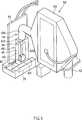
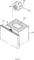
Die
ein Gehäuse
einen Lufteinlauf
eine Ozonaustrittsöffnung
ein Abgaberohr
einen Ozonerzeuger
einen Fluidsensor
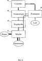
einen Controller
a
an
an ozone exit opening
a
an
a
a
Dadurch kann die Erfindung durch den Luftunterdruck die Ozonversorgung steuern.As a result, the invention can control the ozone supply through the negative air pressure.
Nachfolgend werden die möglichen Ausführungsbeispiele der Erfindung beschrieben:
Wie aus den
Like from the
Wie aus
Wie aus
Wie aus
Nachfolgend wird die Funktionsweise der Erfindung beschrieben:
Wie aus den
Like from the
Der Zielgegenstand
Vorteile der Erfindung:Advantages of the invention:
Der erfindungsgemäße von einem gasförmigen Fluid einschaltbare Ozonversorger weist ein Gehäuse, ein Abgaberohr, einen Ozonerzeuger und einen Fluidsensor auf und kann im Vergleich mit dem Stand der Technik durch die Saugkraft beim Wasseraustritt im Abgaberohr einen Unterdruck erzeugen, durch den die Ozonversorgung gesteuert werden kann, so dass eine Unterbrechung der Ozonversorgung durch Fremdkörper oder Schmutz im Wasser vermieden werden kann.The gaseous fluid switchable ozone supplier according to the present invention comprises a housing, a discharge pipe, an ozone generator and a fluid sensor, and can generate a negative pressure by the suction force at the water outlet in the discharge pipe as compared with the prior art by which the ozone supply can be controlled that an interruption of the ozone supply by foreign bodies or dirt in the water can be avoided.
Die vorstehende Beschreibung stellt nur die bevorzugten Ausführungsbeispiele der Erfindung dar und soll nicht als Definition der Grenzen und des Bereiches der Erfindung dienen. Alle gleichwertige Änderungen und Modifikationen gehören zum Schutzbereich dieser Erfindung.The foregoing description represents only the preferred embodiments of the invention and is not intended to serve as a definition of the limits and scope of the invention. All equivalent changes and modifications are within the scope of this invention.
Claims (6)
Translated fromGermanPriority Applications (1)
| Application Number | Priority Date | Filing Date | Title |
|---|---|---|---|
| DE102012018278.3ADE102012018278B4 (en) | 2012-09-14 | 2012-09-14 | From a gaseous fluid switchable ozone supplier |
Applications Claiming Priority (1)
| Application Number | Priority Date | Filing Date | Title |
|---|---|---|---|
| DE102012018278.3ADE102012018278B4 (en) | 2012-09-14 | 2012-09-14 | From a gaseous fluid switchable ozone supplier |
Publications (2)
| Publication Number | Publication Date |
|---|---|
| DE102012018278A1true DE102012018278A1 (en) | 2014-04-03 |
| DE102012018278B4 DE102012018278B4 (en) | 2015-06-25 |
Family
ID=50276045
Family Applications (1)
| Application Number | Title | Priority Date | Filing Date |
|---|---|---|---|
| DE102012018278.3AExpired - Fee RelatedDE102012018278B4 (en) | 2012-09-14 | 2012-09-14 | From a gaseous fluid switchable ozone supplier |
Country Status (1)
| Country | Link |
|---|---|
| DE (1) | DE102012018278B4 (en) |
Cited By (2)
| Publication number | Priority date | Publication date | Assignee | Title |
|---|---|---|---|---|
| CN106139193A (en)* | 2016-08-24 | 2016-11-23 | 广州市德百顺电气科技有限公司 | A kind of multifunctional ozone watering can |
| CN109205565A (en)* | 2018-10-02 | 2019-01-15 | 殷洪斌 | A kind of uv light induction bend pipe ozone generating apparatus and its method for generation |
Citations (3)
| Publication number | Priority date | Publication date | Assignee | Title |
|---|---|---|---|---|
| JPH08203400A (en)* | 1995-01-27 | 1996-08-09 | Saginomiya Seisakusho Inc | Flow switch |
| US6030586A (en)* | 1998-10-30 | 2000-02-29 | Kuan; Yu-Hung | Ozone generating and ozone/water mixing apparatus |
| DE102005041166A1 (en)* | 2004-09-03 | 2006-04-06 | Smith, Kenneth G. | Apparatus for enriching medium, especially water or air, with ozone, e.g. process or fresh water, food treatment water, vehicle air conditioner or air in refrigerator or cold store, has automated ozone feed from generator to medium |
- 2012
- 2012-09-14DEDE102012018278.3Apatent/DE102012018278B4/ennot_activeExpired - Fee Related
Patent Citations (3)
| Publication number | Priority date | Publication date | Assignee | Title |
|---|---|---|---|---|
| JPH08203400A (en)* | 1995-01-27 | 1996-08-09 | Saginomiya Seisakusho Inc | Flow switch |
| US6030586A (en)* | 1998-10-30 | 2000-02-29 | Kuan; Yu-Hung | Ozone generating and ozone/water mixing apparatus |
| DE102005041166A1 (en)* | 2004-09-03 | 2006-04-06 | Smith, Kenneth G. | Apparatus for enriching medium, especially water or air, with ozone, e.g. process or fresh water, food treatment water, vehicle air conditioner or air in refrigerator or cold store, has automated ozone feed from generator to medium |
Cited By (2)
| Publication number | Priority date | Publication date | Assignee | Title |
|---|---|---|---|---|
| CN106139193A (en)* | 2016-08-24 | 2016-11-23 | 广州市德百顺电气科技有限公司 | A kind of multifunctional ozone watering can |
| CN109205565A (en)* | 2018-10-02 | 2019-01-15 | 殷洪斌 | A kind of uv light induction bend pipe ozone generating apparatus and its method for generation |
Also Published As
| Publication number | Publication date |
|---|---|
| DE102012018278B4 (en) | 2015-06-25 |
Similar Documents
| Publication | Publication Date | Title |
|---|---|---|
| DE60001624T2 (en) | Device for atomizing a liquid, in particular for medical applications | |
| DE2439220A1 (en) | AIR INLET DEVICE FOR A HYDROMASSAGE TUB | |
| DE102006062082A1 (en) | Supply air device and method for controlling the amount of air flow | |
| DE19923351A1 (en) | Liquid pump arrangement, in particular for use in the home and / or garden | |
| DE202009014465U1 (en) | Device in the form of a compressed air lift | |
| DE102012018278A1 (en) | Ozone supplier switchable by gaseous fluid comprises housing comprising receiving chamber, air inlet, ozone outlet opening, discharge tube comprising connecting end and discharge end, ozone generator, and fluid sensor | |
| WO2022023487A1 (en) | Sanitary fitting with a mutli-function option and hybrid operation | |
| DE102010028729B4 (en) | Milk frother with non-return valve | |
| DE102015118938B4 (en) | Fluid valve and water supply system with fluid valve | |
| DE1491849B1 (en) | Respirator | |
| DE102011008303B4 (en) | Sink with water tap | |
| WO2016034279A1 (en) | Water preparation device for a dental treatment unit | |
| DE10205655A1 (en) | Water disinfecting assembly has quartz glass tube through which water flows, surrounded by housing with ultra-violet light source, and including cleaning stopper that passes through tube with water | |
| DE808934C (en) | Pipe ventilator with valve closure through float body | |
| AT500874B1 (en) | ISSUE VALVE | |
| DE19737490A1 (en) | Method for operating a high pressure device, in particular a high pressure cleaner and high pressure device | |
| DE3625323A1 (en) | Albumin skimmer for an aquarium | |
| DE202007008808U1 (en) | Water saving device for showers | |
| DE102022120306B3 (en) | Connection head for a filter candle and installation system | |
| EP3351693A1 (en) | Sanitary outlet part and corresponding use | |
| WO2013131617A1 (en) | Shower attachment | |
| DE2021715B2 (en) | Pipe aerator for connection to a water tap of a bar counter or the like | |
| DE202011005437U1 (en) | Mist-forming health-promoting cleaning device | |
| CH622086A5 (en) | Combined home air-conditioning and home therapeutic device | |
| DE2729198B1 (en) | Device for regulating the air supply for air bubble mats in air bubble massage baths |
Legal Events
| Date | Code | Title | Description |
|---|---|---|---|
| R012 | Request for examination validly filed | ||
| R016 | Response to examination communication | ||
| R016 | Response to examination communication | ||
| R018 | Grant decision by examination section/examining division | ||
| R020 | Patent grant now final | ||
| R082 | Change of representative | ||
| R119 | Application deemed withdrawn, or ip right lapsed, due to non-payment of renewal fee |