DE102012007762A1 - Oil filter of an internal combustion engine and oil filter element of an oil filter - Google Patents
Oil filter of an internal combustion engine and oil filter element of an oil filterDownload PDFInfo
- Publication number
- DE102012007762A1 DE102012007762A1DE102012007762ADE102012007762ADE102012007762A1DE 102012007762 A1DE102012007762 A1DE 102012007762A1DE 102012007762 ADE102012007762 ADE 102012007762ADE 102012007762 ADE102012007762 ADE 102012007762ADE 102012007762 A1DE102012007762 A1DE 102012007762A1
- Authority
- DE
- Germany
- Prior art keywords
- oil
- oil filter
- filter
- housing
- end body
- Prior art date
- Legal status (The legal status is an assumption and is not a legal conclusion. Google has not performed a legal analysis and makes no representation as to the accuracy of the status listed.)
- Withdrawn
Links
- 238000002485combustion reactionMethods0.000titleclaimsabstractdescription15
- 230000002093peripheral effectEffects0.000claimsabstractdescription14
- 230000007423decreaseEffects0.000claimsdescription3
- 239000011888foilSubstances0.000claimsdescription2
- 239000003921oilSubstances0.000description83
- 239000010705motor oilSubstances0.000description11
- 239000012528membraneSubstances0.000description8
- 230000004888barrier functionEffects0.000description7
- 238000000034methodMethods0.000description7
- 238000007789sealingMethods0.000description7
- 230000008901benefitEffects0.000description6
- 229920003023plasticPolymers0.000description6
- 239000004033plasticSubstances0.000description6
- 230000000694effectsEffects0.000description4
- 239000010687lubricating oilSubstances0.000description4
- 239000000463materialSubstances0.000description4
- 229920005830Polyurethane FoamPolymers0.000description2
- 239000000956alloySubstances0.000description2
- 229910045601alloyInorganic materials0.000description2
- 229910052782aluminiumInorganic materials0.000description2
- XAGFODPZIPBFFR-UHFFFAOYSA-NaluminiumChemical compound[Al]XAGFODPZIPBFFR-UHFFFAOYSA-N0.000description2
- 238000005530etchingMethods0.000description2
- 238000002347injectionMethods0.000description2
- 239000007924injectionSubstances0.000description2
- 229910052751metalInorganic materials0.000description2
- 239000002184metalSubstances0.000description2
- 238000003801millingMethods0.000description2
- 239000000203mixtureSubstances0.000description2
- 238000000465mouldingMethods0.000description2
- 229920002635polyurethanePolymers0.000description2
- 239000004814polyurethaneSubstances0.000description2
- 230000008092positive effectEffects0.000description2
- 230000008569processEffects0.000description2
- 239000007858starting materialSubstances0.000description2
- BUHVIAUBTBOHAG-FOYDDCNASA-N(2r,3r,4s,5r)-2-[6-[[2-(3,5-dimethoxyphenyl)-2-(2-methylphenyl)ethyl]amino]purin-9-yl]-5-(hydroxymethyl)oxolane-3,4-diolChemical compoundCOC1=CC(OC)=CC(C(CNC=2C=3N=CN(C=3N=CN=2)[C@H]2[C@@H]([C@H](O)[C@@H](CO)O2)O)C=2C(=CC=CC=2)C)=C1BUHVIAUBTBOHAG-FOYDDCNASA-N0.000description1
- KXGFMDJXCMQABM-UHFFFAOYSA-N2-methoxy-6-methylphenolChemical compound[CH]OC1=CC=CC([CH])=C1OKXGFMDJXCMQABM-UHFFFAOYSA-N0.000description1
- 229920000459Nitrile rubberPolymers0.000description1
- 230000001914calming effectEffects0.000description1
- 238000005266castingMethods0.000description1
- 238000004140cleaningMethods0.000description1
- 230000003247decreasing effectEffects0.000description1
- 238000005187foamingMethods0.000description1
- 238000001746injection mouldingMethods0.000description1
- 238000003780insertionMethods0.000description1
- 230000037431insertionEffects0.000description1
- 230000003993interactionEffects0.000description1
- 239000007788liquidSubstances0.000description1
- 238000004519manufacturing processMethods0.000description1
- 238000002844meltingMethods0.000description1
- 230000008018meltingEffects0.000description1
- 238000012986modificationMethods0.000description1
- 230000004048modificationEffects0.000description1
- 229920001568phenolic resinPolymers0.000description1
- 239000005011phenolic resinSubstances0.000description1
- 230000009467reductionEffects0.000description1
- 239000007787solidSubstances0.000description1
- 238000009827uniform distributionMethods0.000description1
- 238000003466weldingMethods0.000description1
Images


Classifications
- B—PERFORMING OPERATIONS; TRANSPORTING
- B01—PHYSICAL OR CHEMICAL PROCESSES OR APPARATUS IN GENERAL
- B01D—SEPARATION
- B01D35/00—Filtering devices having features not specifically covered by groups B01D24/00 - B01D33/00, or for applications not specifically covered by groups B01D24/00 - B01D33/00; Auxiliary devices for filtration; Filter housing constructions
- B01D35/14—Safety devices specially adapted for filtration; Devices for indicating clogging
- B01D35/147—Bypass or safety valves
- B—PERFORMING OPERATIONS; TRANSPORTING
- B01—PHYSICAL OR CHEMICAL PROCESSES OR APPARATUS IN GENERAL
- B01D—SEPARATION
- B01D35/00—Filtering devices having features not specifically covered by groups B01D24/00 - B01D33/00, or for applications not specifically covered by groups B01D24/00 - B01D33/00; Auxiliary devices for filtration; Filter housing constructions
- B01D35/14—Safety devices specially adapted for filtration; Devices for indicating clogging
- B01D35/153—Anti-leakage or anti-return valves
- F—MECHANICAL ENGINEERING; LIGHTING; HEATING; WEAPONS; BLASTING
- F01—MACHINES OR ENGINES IN GENERAL; ENGINE PLANTS IN GENERAL; STEAM ENGINES
- F01M—LUBRICATING OF MACHINES OR ENGINES IN GENERAL; LUBRICATING INTERNAL COMBUSTION ENGINES; CRANKCASE VENTILATING
- F01M11/00—Component parts, details or accessories, not provided for in, or of interest apart from, groups F01M1/00 - F01M9/00
- F01M11/03—Mounting or connecting of lubricant purifying means relative to the machine or engine; Details of lubricant purifying means
- B—PERFORMING OPERATIONS; TRANSPORTING
- B01—PHYSICAL OR CHEMICAL PROCESSES OR APPARATUS IN GENERAL
- B01D—SEPARATION
- B01D2201/00—Details relating to filtering apparatus
- B01D2201/29—Filter cartridge constructions
- B01D2201/291—End caps
- B—PERFORMING OPERATIONS; TRANSPORTING
- B01—PHYSICAL OR CHEMICAL PROCESSES OR APPARATUS IN GENERAL
- B01D—SEPARATION
- B01D2201/00—Details relating to filtering apparatus
- B01D2201/29—Filter cartridge constructions
- B01D2201/291—End caps
- B01D2201/295—End caps with projections extending in a radial outward direction, e.g. for use as a guide, spacing means
- B—PERFORMING OPERATIONS; TRANSPORTING
- B01—PHYSICAL OR CHEMICAL PROCESSES OR APPARATUS IN GENERAL
- B01D—SEPARATION
- B01D2201/00—Details relating to filtering apparatus
- B01D2201/30—Filter housing constructions
- B01D2201/301—Details of removable closures, lids, caps, filter heads
- B01D2201/305—Snap, latch or clip connecting means
Landscapes
- Engineering & Computer Science (AREA)
- Chemical & Material Sciences (AREA)
- Chemical Kinetics & Catalysis (AREA)
- Mechanical Engineering (AREA)
- General Engineering & Computer Science (AREA)
- Lubrication Details And Ventilation Of Internal Combustion Engines (AREA)
Abstract
Translated fromGermanDescription
Translated fromGermanTechnisches GebietTechnical area
Die Erfindung betrifft einen Ölfilter einer Brennkraftmaschine insbesondere eines Kraftfahrzeugs mit einem Filtergehäuse, welches einen Gehäusetopf, einen mit diesem trennbar verbundenen Gehäusedeckel, wenigstens einen Öleinlass und wenigstens einen Ölauslass aufweist und in dem ein austauschbares Ölfilterelement so angeordnet ist, dass es den wenigstens einen Öleinlass von dem wenigstens einen Ölauslass trennt, und das Ölfilterelement ein Filtermedium umfasst, das einen Innenraum des Ölfilterelements umfangsmäßig geschlossen umgibt und das wenigstens an einer deckelseitigen Stirnseite mit einem Endkörper dicht verbunden ist, und eine Mehrzahl von Stützelementabschnitten zwischen dem Filtermedium und einer Innenseite des Gehäusedeckels angeordnet ist.The invention relates to an oil filter of an internal combustion engine, in particular of a motor vehicle with a filter housing having a housing pot, a housing cover separably connected to this, at least one oil inlet and at least one oil outlet and in which a replaceable oil filter element is arranged so that it at least one oil inlet of the at least one oil outlet separates, and the oil filter element comprises a filter medium which surrounds an interior of the oil filter element circumferentially closed and which is at least at a lid-side end side with an end body tightly connected, and a plurality of support member sections between the filter medium and an inside of the housing cover is arranged ,
Ferner betrifft die Erfindung ein Ölfilterelement eines Ölfilters einer Brennkraftmaschine insbesondere eines Kraftfahrzeugs, welches austauschbar in einem Filtergehäuse mit wenigstens einem Öleinlass und wenigstens einem Ölauslass, welches einen Gehäusetopf und einen mit diesem trennbar verbundenen Gehäusedeckel aufweist, so angeordnet werden kann, dass es den wenigstens einen Öleinlass von dem wenigstens einen Ölauslass trennt, und das ein Filtermedium umfasst, das einen Innenraum des Ölfilterelements umfangsmäßig geschlossen umgibt und das wenigstens an einer deckelseitigen Stirnseite mit einem Endkörper dicht verbunden ist.Furthermore, the invention relates to an oil filter element of an oil filter of an internal combustion engine, in particular of a motor vehicle, which can be arranged interchangeable in a filter housing with at least one oil inlet and at least one oil outlet, which has a housing pot and a housing cover separably connected to this, that it at least one Oil inlet of the at least one oil outlet separates, and which comprises a filter medium which surrounds an interior of the oil filter element circumferentially closed and which is at least at a lid-side end side with a terminal body tightly connected.
Stand der TechnikState of the art
Aus der
Der Erfindung liegt die Aufgabe zugrunde, einen Ölfilter und ein Ölfilterelement der eingangs genannten Art zu gestalten, bei denen ein Differenzdruck zwischen der Rohseite und der Reinseite des Filtermediums begrenzt werden kann.The invention has for its object to design an oil filter and an oil filter element of the type mentioned, in which a differential pressure between the raw side and the clean side of the filter medium can be limited.
Offenbarung der ErfindungDisclosure of the invention
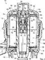
Diese Aufgabe wird erfindungsgemäß dadurch gelöst, dass eine Bypassleitung mit einem Umgehungsventil zur Umgehung des Ölfilterelements einen radial äußeren Ringraum, der zwischen der radial äußeren Umfangsseite des Filtermediums und einer radial inneren Umfangsseite des Filtergehäuses angeordnet ist, über eine Bypassöffnung in dem deckelseitigen Endkörper mit dem Innenraum des Ölfilterelements verbindet, die Stützelementabschnitte am deckelseitige Endkörper angeordnet sind und in Umfangsrichtung benachbarte Stützelementabschnitte wenigstens einen Strömungskanal der Bypassleitung begrenzen.This object is achieved in that a bypass line with a bypass valve for bypassing the oil filter element, a radially outer annular space which is disposed between the radially outer peripheral side of the filter medium and a radially inner peripheral side of the filter housing, via a bypass opening in the lid-side end body with the interior the oil filter element connects, the support member sections are arranged on the cover-side end body and circumferentially adjacent support member sections define at least one flow channel of the bypass line.
Erfindungsgemäß ist also eine Bypassleitung vorgesehen, mit der das Filtermedium strömungstechnisch umgangen werden kann. In der Bypassleitung ist ein Umgehungsventil angeordnet, mit dem ein Grenz-Differenzdruck zwischen der Rohseite und der Reinseite, ab welchem die Bypassleitung geöffnet werden soll, vorgegeben ist. Bei Überschreitung des Grenz-Differenzdrucks öffnet das Umgehungsventil und gibt die Bypassleitung frei. Das Öl fließt dann durch die Bypassleitung an dem Filtermedium vorbei vom Einlass zum Auslass. Der Differenzdruck zwischen Reinseite und Rohseite wird so abgebaut und das Filtermedium vor Beschädigung geschützt. Die Bypassleitung führt von dem Ringraum, welcher das Filtermedium umgibt, durch den wenigstens einen Strömungskanal im deckelseitigen Endkörper und die Bypassöffnung im deckelseitigen Endkörper in den Innenraum des Ölfilterelements. Das Filtermedium kann von dem zu reinigenden Öl unter normalen Bedingungen bei geschlossener Bypassleitung von radial außen nach innen oder von radial innen nach außen durchströmt werden. Zwischen der Innenseite des Gehäusedeckels und dem deckelseitigen Endkörper kann ein Verbindungskanal oder ein Verbindungsraum gebildet sein, welcher den wenigstens einen Strömungskanal indirekt mit der deckelseitigen Bypassöffnung verbindet. Der wenigstens eine Strömungskanal kann aber auch direkt in die deckelseitige Bypassöffnung münden. Der wenigstens eine Strömungskanal kann einer aus einer Mehrzahl von Strömungskanälen der Bypassleitung sein. Somit kann vorteilhafterweise auch eine Mehrzahl von Strömungskanälen jeweils durch umfangsmäßig benachbarte Stützelementabschnitte begrenzt werden. Bei den Stützelementabschnitten kann es sich um Abschnitte von separaten Stützelementen handeln. Die Stützelementabschnitte können aber auch zu einem einzigen Stützelement gehören. Insbesondere kann das Stützelement umfangsmäßig in der Art eines offenen Ringes verlaufen, wobei die Öffnung des Rings den einen Strömungskanal bildet. Vorteilhafterweise können die Stützelementabschnitte und der wenigstens eine Strömungskanal auch Teile eines Adapterelements sein, welches zwischen dem deckelseitigen Endkörper und der Innenseite des Gehäusedeckels angeordnet werden kann. Das Adapterelement kann mit dem deckelseitigen Endkörper oder dem Gehäusedeckel verbunden sein.According to the invention, therefore, a bypass line is provided, with which the filter medium can be bypassed fluidically. In the bypass line, a bypass valve is arranged, with which a limit differential pressure between the raw side and the clean side, from which the bypass line is to be opened, is specified. When the limit differential pressure is exceeded, the bypass valve opens and releases the bypass line. The oil then flows through the bypass line past the filter media from the inlet to the outlet. The differential pressure between the clean side and the raw side is reduced and the filter medium is protected from damage. The bypass line leads from the annular space, which surrounds the filter medium, through the at least one flow channel in the cover-side end body and the bypass opening in the cover-side end body in the interior of the oil filter element. The filter medium can be flowed through by the oil to be cleaned under normal conditions with closed bypass line from radially outside to inside or from radially inside to outside. Between the inside of the housing cover and the lid-side end body, a connecting channel or a connecting space may be formed, which indirectly to the at least one flow channel cover-side bypass opening connects. The at least one flow channel can also open directly into the cover-side bypass opening. The at least one flow channel may be one of a plurality of flow channels of the bypass line. Thus, advantageously, a plurality of flow channels can be limited in each case by circumferentially adjacent support element sections. The support element sections may be sections of separate support elements. But the support member sections may also belong to a single support element. In particular, the support member may extend circumferentially in the manner of an open ring, wherein the opening of the ring forms the one flow channel. Advantageously, the support element sections and the at least one flow channel can also be parts of an adapter element, which can be arranged between the cover-side end body and the inside of the housing cover. The adapter element may be connected to the cover-side end body or the housing cover.
Das Ölfilterelement kann koaxial zu einer Montageachse des Gehäusetopfs mit dem Gehäusedeckel austauschbar in das Filtergehäuse eingesteckt sein. Dreh- und/oder Steckbewegungen des Gehäusedeckels relativ zum Gehäusetopf beim Schließen oder Öffnen des Gehäuses werden um die Montageachse und/oder axial zu dieser durchgeführt. Das Ölfilterelement kann auf ein Mittelrohr aufgesteckt sein. Das Mittelrohr kann fest mit dem Gehäusedeckel oder dem Gehäusetopf verbunden sein. Durch das Mittelrohr kann die Position des Ölfilterelements im Filtergehäuse in radialer Richtung vorgegeben werden. Mit den Stützelementabschnitten kann die Position des Ölfilterelements in axialer Richtung relativ zu dem Gehäusedeckel im Filtergehäuse vorgegeben werden. Ferner kann das Ölfilterelement mit den Stützelementabschnitten in axialer Richtung gegen den Boden des Gehäusetopfs verspannt werden.The oil filter element can be exchangeably inserted into the filter housing coaxially with a mounting axis of the housing pot with the housing cover. Rotary and / or insertion movements of the housing cover relative to the housing pot when closing or opening the housing are performed around the mounting axis and / or axially thereto. The oil filter element can be plugged onto a central tube. The central tube may be firmly connected to the housing cover or the housing pot. Through the central tube, the position of the oil filter element in the filter housing can be specified in the radial direction. With the support member sections, the position of the oil filter element in the axial direction relative to the housing cover in the filter housing can be specified. Furthermore, the oil filter element can be braced with the support member sections in the axial direction against the bottom of the housing pot.
Vorzugsweise kann am Boden des Gehäusetopfs der Innenraum des Ölfilterelements mit dem Ölauslass oder dem Öleinlass verbunden sein. Die Verbindung kann eine Dichtungseinrichtung aufweisen. Durch die Verspannung mittels der Stützelementabschnitte kann die Dichtungswirkung dieser Dichtungseinrichtung verbessert werden.Preferably, the interior of the oil filter element may be connected to the oil outlet or the oil inlet at the bottom of the housing pot. The connection may comprise a sealing device. By the tension by means of the support element sections, the sealing effect of this sealing device can be improved.
Der wenigstens eine Strömungskanal im Endkörper kann eine Strömung des Öls zwischen dem Ringraum und der Bypassöffnung verbessern. So kann das Öl bei offenem Umgehungsventil optimal insbesondere mit geringem Druckverlust durch die Bypassleitung strömen.The at least one flow channel in the end body can improve a flow of the oil between the annulus and the bypass opening. Thus, the oil can flow optimally with open bypass valve, in particular with low pressure loss through the bypass line.
Der wenigstens eine Strömungskanal kann strömungstechnisch optimiert sein. Die Stützelementabschnitte und der wenigstens eine Strömungskanal können einfach am Endkörper angeordnet werden. Die Stützelementabschnitte können zusätzlich zu ihrer Stützfunktion auch die Form, den Verlauf und/oder die Größe des wenigstens einen Strömungskanals vorgegeben. Zusätzliche, die Strömung des Öls beeinflussende Strömungselement, sind nicht erforderlich.The at least one flow channel can be optimized in terms of flow. The support element sections and the at least one flow channel can be easily arranged on the end body. In addition to their support function, the support element sections can also specify the shape, the course and / or the size of the at least one flow channel. Additional, affecting the flow of the oil flow element are not required.
Das Filtermedium kann vorteilhafterweise sternförmig gefaltet sein, wodurch einfach eine im Verhältnis zu den Außenmaßen des Filtermediums große aktive Filterfläche realisiert werden kann. Vorteilhafterweise kann das Filtermedium in koaxialer Form realisiert sein, so dass ein gedachter Innenmantel, welcher die radial innere Umfangsseite des Filtermediums definiert, koaxial zu einem gedachten Außenmantel, welcher die radial äußere Umfangsseite des Filtermediums definiert, verläuft. Auf diese Weise kann das Verhältnis zwischen der aktiven Filteroberfläche und den Außenmaßen des Filtermediums weiter verbessert werden.The filter medium can advantageously be folded in a star shape, whereby a large active filter area, which is large in relation to the external dimensions of the filter medium, can be easily realized. Advantageously, the filter medium can be realized in coaxial form, so that an imaginary inner jacket, which defines the radially inner peripheral side of the filter medium, coaxial with an imaginary outer shell, which defines the radially outer circumferential side of the filter medium extends. In this way, the ratio between the active filter surface and the outer dimensions of the filter medium can be further improved.
Bei einer vorteilhaften Ausführungsform können die Stützelementabschnitte sich bezüglich dem Filtermedium von radial außen von dem radial äußeren Ringraum nach radial innen erstrecken. Die Breiten der Stützelementabschnitte in Umfangsrichtung können größer oder kleiner sein als deren Längen von radial außen nach radial innen. Mit den Stützelementabschnitten können so entsprechend große und ausgedehnte Anlageflächen des Endkörpers an dem Gehäusedeckel erreicht werden. Die Stützelementabschnitte können sich bis zum Zentrum des Endkörpers erstrecken. Sie können sich aber auch radial betrachtet zwischen dem äußeren Ringraum und dem Zentrum des Endkörpers enden.In an advantageous embodiment, the support element sections may extend radially inwardly from the radially outer annular space with respect to the filter medium. The widths of the support member sections in the circumferential direction may be larger or smaller than their lengths from radially outside to radially inside. With the support member sections so correspondingly large and extended contact surfaces of the end body can be achieved on the housing cover. The support member portions may extend to the center of the end body. However, they can also end up radially between the outer annulus and the center of the end body.
Vorteilhafterweise kann der wenigstens eine Strömungskanal in der dem Filtermedium abgewandten Außenseite des Endkörpers angeordnet sein. Auf diese Weise kann auf eine separate Abdichtung des wenigstens einen Strömungskanals zum Filtermedium hin verzichtet werden.Advantageously, the at least one flow channel can be arranged in the outside of the end body facing away from the filter medium. In this way, it is possible to dispense with a separate sealing of the at least one flow channel to the filter medium.
Ferner kann vorteilhafterweise der wenigstens eine Strömungskanal sich von radial außen von dem radial äußeren Ringraum, mit diesem verbunden, nach radial innen erstrecken. Der wenigstens eine Strömungskanal kann so einfach den radial äußeren Ringraum mit einem radial weiter innen gelegenen Raum der Bypassleitung verbinden.Furthermore, advantageously, the at least one flow channel can extend radially inwards from the radially outer annular space, connected thereto. The at least one flow channel can thus easily connect the radially outer annular space with a radially further inward space of the bypass line.
Bei einer weiteren vorteilhaften Ausführungsform kann der Endkörper eine sogenannte Folienendscheibe sein. Folienendscheiben sind im Stand der Technik bekannt. Hinsichtlich der Beschaffenheit der Folienendscheibe wird auf die
Der wenigstens eine Strömungskanal kann vorzugsweise eine Nut in der dem Filtermedium abgewandten Außenseite der Folienendscheibe und die Stützelementabschnitte können Vorsprünge der Folienendscheibe neben der Nut sein. Die Folienendscheibe kann vorteilhafterweise auf die Stirnseite des Filtermediums aufgeschäumt bzw. aufgeschmolzen sein. Sind mehrere Strömungskanäle in Form von Nuten vorgesehen, so können die Stützelemente Vorsprünge der Folienendscheibe zwischen den Nuten sein.The at least one flow channel may preferably have a groove in the outside of the film end disk facing away from the filter medium, and the support element sections may be projections of the film end disk adjacent to the groove. The film end disk can advantageously be foamed or melted onto the end face of the filter medium. If a plurality of flow channels provided in the form of grooves, the support elements may be projections of the film end between the grooves.
Der Endkörper kann aber auch eine Kunststoffendscheibe sein, welche nach einem Schweißverfahren mit dem Filtermedium verbunden ist. Die Endscheibe kann auch aus einem PUR(Polyurethan)-Schaum sein. Nuten können einfach insbesondere nach einem Form-, Spritz- oder Gussverfahren in die Endscheibe eingebracht werden. Die Nuten können auch nach einem abtragenden Verfahren, insbesondere mittels Fräsen oder einem Ätzverfahren, realisiert sein.The end body may also be a plastic end disk, which is connected to the filter medium by a welding process. The end plate may also be made of a polyurethane (polyurethane) foam. Grooves can simply be introduced into the end disk, in particular by a molding, injection or casting process. The grooves can also be realized by a removing method, in particular by means of milling or an etching method.
Bei einer weiteren vorteilhaften Ausführungsform kann eine Mehrzahl von Strömungskanälen umfangsmäßig vorzugsweise gleichmäßig an der dem Filtermedium abgewandten Außenseite des Endkörpers verteilt sein. Dies hat den Vorteil, dass der Ringraum entlang des gesamten Umfangs des Endkörpers mit Strömungskanälen verbunden ist. Auf diese Weise kann eine Strömung des Öls durch die Bypassleitung, insbesondere eine Anströmung des Umgehungsventils, verbessert werden. Auf diese Weise wird ein Ausgleich des Differenzdrucks zwischen der Rohseite und der Reinseite des Filterelements mittels der Bypassleitung verbessert. Vorteilhafterweise können die Strömungskanäle gleich sein. Somit kann die Gleichmäßigkeit der Strömung des Öls durch die Bypassleitung weiter verbessert werden.In a further advantageous embodiment, a plurality of flow channels may be circumferentially distributed preferably uniformly on the outside of the end body facing away from the filter medium. This has the advantage that the annular space is connected along the entire circumference of the end body with flow channels. In this way, a flow of the oil through the bypass line, in particular an inflow of the bypass valve can be improved. In this way, a compensation of the differential pressure between the raw side and the clean side of the filter element is improved by means of the bypass line. Advantageously, the flow channels can be the same. Thus, the uniformity of the flow of the oil through the bypass passage can be further improved.
Vorteilhafterweise kann sich der wenigstens eine Strömungskanal in radialer Richtung erstrecken. Auf diese Weise kann wenigstens ein kurzer Strömungskanal und wenigstens ein kurzer Strömungsweg realisiert werden. Kurze Strömungskanäle können einfach und platzsparend realisiert werden. Ferner wirken sich kurze Strömungskanäle positiv auf den Strömungsverlauf aus. Insbesondere kann die Strömung weiter beruhigt werden.Advantageously, the at least one flow channel can extend in the radial direction. In this way, at least one short flow channel and at least one short flow path can be realized. Short flow channels can be realized in a simple and space-saving manner. Furthermore, short flow channels have a positive effect on the flow path. In particular, the flow can be calmed down further.
Ferner kann vorteilhafterweise ein Strömungsquerschnitt, insbesondere eine axiale Tiefe, des wenigstens einen Strömungskanals nach radial innen hin abnehmen. Auf diese Weise kann die Strömung in dem wenigstens einen Strömungskanal verbessert werden. Insbesondere kann die Strömung weiter beruhigt werden.Furthermore, a flow cross-section, in particular an axial depth, of the at least one flow channel can advantageously decrease radially inward. In this way, the flow in the at least one flow channel can be improved. In particular, the flow can be calmed down further.
Bei einer weiteren vorteilhaften Ausführungsform können der Endkörper und die Innenseite des Gehäusedeckels einen stirnseitigen Bypassraum begrenzen, der mit dem wenigstens einen Strömungskanal und der Bypassöffnung verbunden sein kann. Der Bypassraum kann ein Ausgleichsvolumen bilden. Er kann zur weiteren Beruhigung der Strömung beitragen. Mit dem Ausgleichsvolumen kann die Öffnungs- und Schließcharakteristik des Umgehungsventils verbessert werden. Insbesondere kann so bewirkt werden, dass das Umgehungsventil gleichmäßiger geöffnet und geschlossen werden kann. Außerdem kann die Strömung des Öls durch die Bypassleitung mittels dem Bypassraum weiter beruhigt werden.In a further advantageous embodiment, the end body and the inside of the housing cover can limit an end-side bypass space, which can be connected to the at least one flow channel and the bypass opening. The bypass chamber can form a compensation volume. He can contribute to further calm the flow. With the compensation volume, the opening and closing characteristics of the bypass valve can be improved. In particular, it can be effected so that the bypass valve can be opened and closed more uniformly. In addition, the flow of the oil through the bypass line by means of the bypass chamber can be further calmed.
Vorteilhafterweise kann an der dem Endkörper zugewandten Innenseite des Gehäusedeckels wenigstens ein Gegenstützkörper, insbesondere ein umlaufender Steg, angeordnet sein, an dem sich die Stützelementabschnitte des Endkörpers abstützen können. Der Gegenstützkörper kann einen definierten Anschlag für die Stützelemente des Endkörpers bilden. Ein umlaufender Steg hat den Vorteil, dass beim Einbau des Ölfilterelements nicht auf die Orientierung der Stützelementabschnitte gegenüber dem Gegenstützkörper geachtet werden muss. Ein umlaufender Steg kann darüber hinaus einfach im Gehäusedeckel realisiert werden. Vorteilhafterweise kann die Ausdehnung des Steges in radialer Richtung wenigstens zwischen etwa 1% bis 10% eines Außendurchmessers eines Außenmantels des Filtermediums betragen, welcher die radial äußere Umfangsseite des Filtermediums definiert. Auf diese Weise bietet der Steg eine entsprechend große Anlagefläche für die Stützelementabschnitte. Dies wirkt sich positiv auf die Stützwirkung aus. Insbesondere bei Verwendung eines weichen deckelseitigen Endkörpers, insbesondere einer Folienendscheibe, ist eine großflächige Stützwirkung von großem Vorteil. Vorteilhafterweise können die Ausdehnungen der Stützelementabschnitte in radialer Richtung wenigstens so groß sein wie die Ausdehnung des Steges in radialer Richtung. Auf diese Weise kann die Anlagefläche vergrößert und damit die Stützwirkung weiter verbessert werden.Advantageously, on the end body facing the inside of the housing cover at least one counter-support body, in particular a circumferential web, may be arranged, on which the support element portions of the end body can be supported. The counter-support body can form a defined stop for the support elements of the end body. A circumferential web has the advantage that when installing the oil filter element, it is not necessary to pay attention to the orientation of the support element sections relative to the counter-support body. A circumferential web can also be easily realized in the housing cover. Advantageously, the extent of the web in the radial direction can be at least between about 1% to 10% of an outer diameter of an outer jacket of the filter medium, which defines the radially outer peripheral side of the filter medium. In this way, the web provides a correspondingly large contact surface for the support element sections. This has a positive effect on the support effect. In particular, when using a soft cover-side end body, in particular a film end, a large-scale support effect of great advantage. Advantageously, the dimensions of the support element sections in the radial direction can be at least as great as the extent of the web in the radial direction. In this way, the contact surface can be increased and thus the support effect can be further improved.
Bei einer weiteren vorteilhaften Ausführungsform kann das Umgehungsventil im Innenraum des Ölfilterelements angeordnet sein. Auf diese Weise kann das Umgehungsventil platzsparend untergebracht werden. Das Umgehungsventil kann fest mit dem Ölfilterelement verbunden sein. Alternativ kann es auch fest mit dem Filtergehäuse, insbesondere in einem Mittelrohr am Deckel oder am Gehäusetopf, angeordnet sein.In a further advantageous embodiment, the bypass valve in the interior of the Be arranged oil filter element. In this way, the bypass valve can be accommodated to save space. The bypass valve may be fixedly connected to the oil filter element. Alternatively, it may also be arranged fixedly to the filter housing, in particular in a central tube on the cover or on the housing pot.
Ferner wird die Aufgabe erfindungsgemäß mit dem Ölfilterelement dadurch gelöst, dass der Endkörper eine Bypassöffnung zu einem Innenraum des Ölfilterelements aufweist, am Endkörper eine Mehrzahl von Stützelementabschnitten angeordnet ist zur Abstützung gegen eine Innenseite des Gehäusedeckels und in Umfangsrichtung benachbarte Stützelementabschnitte wenigstens einen Strömungskanal einer Bypassleitung begrenzen. Die oben in Verbindung mit dem erfindungsgemäßen Ölfilter aufgezeigten Merkmale und Vorteile gelten für das erfindungsgemäße Ölfilterelement und dessen vorteilhafte Ausgestaltungen entsprechend.Furthermore, the object is achieved with the oil filter element according to the invention in that the end body has a bypass opening to an interior of the oil filter element, a plurality of support element sections arranged on the end body is to support at least one flow channel of a bypass line for support against an inner side of the housing cover and circumferentially adjacent support member sections. The features and advantages shown above in connection with the oil filter according to the invention apply correspondingly to the oil filter element according to the invention and its advantageous embodiments.
Bei einer vorteilhaften Ausführungsform kann das Ölfilterelement koaxial zu einer Montageachse eines Gehäusedeckels mit einem Gehäusetopf in dem Filtergehäuse angeordnet werden. Das Filtermedium kann vorteilhafterweise sternförmig gefaltet sein. Vorteilhafterweise kann es eine koaxiale Form aufweisen. Ferner können vorteilhafterweise die Stützelementabschnitte sich bezüglich dem Filtermedium von radial außen von dem radial äußeren Ringraum nach radial innen erstrecken. Vorteilhafterweise können die Strömungskanäle in der dem Filtermedium abgewandten Außenseite des Endkörpers angeordnet sein. Des weiteren kann vorteilhafterweise der wenigstens eine Strömungskanal sich von radial außen von dem radial äußeren Ringraum, mit diesem verbunden, nach radial innen erstrecken. Es können auch mehrere Strömungskanäle vorgesehen sein, die jeweils mit benachbarten Stützelementabschnitten begrenzt werden. Bei den Stützelementabschnitten kann es sich um Abschnitte von separaten Stützelementen handeln. Die Stützelementabschnitte können aber auch zu einem einzigen Stützelement gehören. Insbesondere kann das Stützelement umfangsmäßig in der Art eines offenen Ringes verlaufen, wobei die Öffnung des Rings den einen Strömungskanal bildet.In an advantageous embodiment, the oil filter element can be arranged coaxially to a mounting axis of a housing cover with a housing pot in the filter housing. The filter medium can advantageously be folded in a star shape. Advantageously, it may have a coaxial shape. Furthermore, the support element sections can advantageously extend radially inward from the radially outer annular space with respect to the filter medium. Advantageously, the flow channels can be arranged in the outside of the end body facing away from the filter medium. Furthermore, advantageously, the at least one flow channel may extend radially inwards from the radially outer annular space, connected thereto. It can also be provided a plurality of flow channels, which are each bounded by adjacent support member sections. The support element sections may be sections of separate support elements. But the support member sections may also belong to a single support element. In particular, the support member may extend circumferentially in the manner of an open ring, wherein the opening of the ring forms the one flow channel.
Kurze Beschreibung der ZeichnungenBrief description of the drawings
Weitere Vorteile, Merkmale und Einzelheiten der Erfindung ergeben sich aus der nachfolgenden Beschreibung, in der Ausführungsbeispiele der Erfindung anhand der Zeichnung näher erläutert werden. Der Fachmann wird die in der Zeichnung, der Beschreibung und den Ansprüchen in Kombination offenbarten Merkmale zweckmäßigerweise auch einzeln betrachten und zu sinnvollen weiteren Kombinationen zusammenfassen. Es zeigen schematischFurther advantages, features and details of the invention will become apparent from the following description, are explained in more detail in the embodiments of the invention with reference to the drawing. The person skilled in the art will expediently also individually consider the features disclosed in combination in the drawing, the description and the claims in combination, and combine these with meaningful further combinations. It show schematically
In den Figuren sind gleiche Bauteile mit gleichen Bezugszeichen versehen.In the figures, the same components are provided with the same reference numerals.
Ausführungsform(en) der ErfindungEmbodiment (s) of the invention
In der
Durch einen Boden des Gehäusetopfs
Im Filtergehäuse
In dem Filtergehäuse
An der dem Gehäusedeckel
An der dem Filtermedium
Ein Abschnitt des Mittelrohrs
Zwischen der anschlussseitigen Endscheibe
Auf ihrer dem Filtermedium
Umfangsmäßig betrachtet zwischen jeweils zwei der Strömungskanäle
Zur Montage des Ölfilters
Der Gehäusedeckel
Beim Betrieb der Brennkraftmaschine fließt Motoröl aus der Ölzuleitung des Motorölkreislaufs durch den Öleinlass
Falls das Motoröl beispielsweise beim Starten der kalten Brennkraftmaschine aufgrund einer geringen Temperatur eine entsprechend hohe Viskosität aufweist, kann es zu einer Erhöhung des Differenzdrucks zwischen der Rohseite und der Reinseite kommen. Da der Ringraum
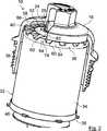
In den
Das Stützelement
Bei den oben beschriebenen Ausführungsbeispielen eines Ölfilters
Die Erfindung ist nicht beschränkt auf einen Ölfilter
The invention is not limited to an
Der Gehäusetopf
Der Gehäusedeckel
Anstelle des sternförmig gefalteten Filtermediums
Die Endscheiben
Die Endscheiben
Die Endscheiben
Die Strömungskanäle
Statt identischer Strömungskanäle
Es können auch mehr oder weniger als die in den Figuren dargestellten und beschriebenen Strömungskanäle
Die Stützvorsprünge
Statt von radial außen nach innen kann das Filtermedium
Anstelle der Rücklaufsperrmembran
ZITATE ENTHALTEN IN DER BESCHREIBUNG QUOTES INCLUDE IN THE DESCRIPTION
Diese Liste der vom Anmelder aufgeführten Dokumente wurde automatisiert erzeugt und ist ausschließlich zur besseren Information des Lesers aufgenommen. Die Liste ist nicht Bestandteil der deutschen Patent- bzw. Gebrauchsmusteranmeldung. Das DPMA übernimmt keinerlei Haftung für etwaige Fehler oder Auslassungen.This list of the documents listed by the applicant has been generated automatically and is included solely for the better information of the reader. The list is not part of the German patent or utility model application. The DPMA assumes no liability for any errors or omissions.
Zitierte PatentliteraturCited patent literature
- DE 202005002955 U1[0003]DE 202005002955 U1[0003]
- EP 0713721 A1[0015]EP 0713721 A1[0015]
Claims (12)
Translated fromGermanPriority Applications (2)
| Application Number | Priority Date | Filing Date | Title |
|---|---|---|---|
| DE102012007762ADE102012007762A1 (en) | 2012-04-20 | 2012-04-20 | Oil filter of an internal combustion engine and oil filter element of an oil filter |
| EP13162930.5AEP2653675B1 (en) | 2012-04-20 | 2013-04-09 | Oil filter of a combustion engine and oil filter element of an oil filter |
Applications Claiming Priority (1)
| Application Number | Priority Date | Filing Date | Title |
|---|---|---|---|
| DE102012007762ADE102012007762A1 (en) | 2012-04-20 | 2012-04-20 | Oil filter of an internal combustion engine and oil filter element of an oil filter |
Publications (1)
| Publication Number | Publication Date |
|---|---|
| DE102012007762A1true DE102012007762A1 (en) | 2013-10-24 |
Family
ID=48095617
Family Applications (1)
| Application Number | Title | Priority Date | Filing Date |
|---|---|---|---|
| DE102012007762AWithdrawnDE102012007762A1 (en) | 2012-04-20 | 2012-04-20 | Oil filter of an internal combustion engine and oil filter element of an oil filter |
Country Status (2)
| Country | Link |
|---|---|
| EP (1) | EP2653675B1 (en) |
| DE (1) | DE102012007762A1 (en) |
Cited By (2)
| Publication number | Priority date | Publication date | Assignee | Title |
|---|---|---|---|---|
| US20210252425A1 (en)* | 2018-09-11 | 2021-08-19 | Mann+Hummel Gmbh | Dryer Cartridge, Drying System, and Use Thereof |
| US11975278B2 (en) | 2020-07-31 | 2024-05-07 | Donaldson Company, Inc. | Valve arrangement, liquid filters, filter assemblies, and method |
Families Citing this family (3)
| Publication number | Priority date | Publication date | Assignee | Title |
|---|---|---|---|---|
| EP3608009A1 (en) | 2018-08-10 | 2020-02-12 | Mann+Hummel GmbH | Filter system and filter element with improved positioning means |
| DE102019122034A1 (en)* | 2018-09-11 | 2020-03-12 | Mann+Hummel Gmbh | Filter element with a receiving space containing a desiccant and fluid filter |
| CN114893275B (en)* | 2022-05-18 | 2023-05-02 | 安徽安凯汽车股份有限公司 | Oil filter with many bypass valves of many filter cores and maintenance device |
Citations (5)
| Publication number | Priority date | Publication date | Assignee | Title |
|---|---|---|---|---|
| EP0713721A1 (en) | 1994-11-23 | 1996-05-29 | Filterwerk Mann + Hummel Gmbh | Filter arrangement |
| DE19711457A1 (en)* | 1997-03-19 | 1998-10-01 | Hengst Walter Gmbh & Co Kg | Internal combustion engine oil filter |
| DE19829989A1 (en)* | 1998-07-04 | 2000-01-05 | Mann & Hummel Filter | Round filter cartridge |
| DE19847998A1 (en)* | 1998-10-17 | 2000-04-20 | Mann & Hummel Filter | Cartridge filter, for use in gas or liquid filtration, has cylindrical element sealed by embedding its ends with thermosetting coupons |
| DE202005002955U1 (en) | 2005-02-23 | 2006-07-06 | Hengst Gmbh & Co.Kg | Filter insert for liquid filters, e.g. oil filters for car engines, has a drainage channel sealed by a plug which forms part of a special unit fixed to the insert by clamping or fixing tongues between the folds of the filter |
Family Cites Families (3)
| Publication number | Priority date | Publication date | Assignee | Title |
|---|---|---|---|---|
| DE3903675A1 (en)* | 1989-02-08 | 1990-08-09 | Knecht Filterwerke Gmbh | Oil filter for cleaning lubrication oil |
| DE20101574U1 (en)* | 2001-01-31 | 2002-06-20 | Ing. Walter Hengst GmbH & Co. KG, 48147 Münster | Liquid filter with direct seal |
| DE102009049868A1 (en)* | 2009-10-20 | 2011-04-21 | Mahle International Gmbh | filtering device |
- 2012
- 2012-04-20DEDE102012007762Apatent/DE102012007762A1/ennot_activeWithdrawn
- 2013
- 2013-04-09EPEP13162930.5Apatent/EP2653675B1/enactiveActive
Patent Citations (5)
| Publication number | Priority date | Publication date | Assignee | Title |
|---|---|---|---|---|
| EP0713721A1 (en) | 1994-11-23 | 1996-05-29 | Filterwerk Mann + Hummel Gmbh | Filter arrangement |
| DE19711457A1 (en)* | 1997-03-19 | 1998-10-01 | Hengst Walter Gmbh & Co Kg | Internal combustion engine oil filter |
| DE19829989A1 (en)* | 1998-07-04 | 2000-01-05 | Mann & Hummel Filter | Round filter cartridge |
| DE19847998A1 (en)* | 1998-10-17 | 2000-04-20 | Mann & Hummel Filter | Cartridge filter, for use in gas or liquid filtration, has cylindrical element sealed by embedding its ends with thermosetting coupons |
| DE202005002955U1 (en) | 2005-02-23 | 2006-07-06 | Hengst Gmbh & Co.Kg | Filter insert for liquid filters, e.g. oil filters for car engines, has a drainage channel sealed by a plug which forms part of a special unit fixed to the insert by clamping or fixing tongues between the folds of the filter |
Cited By (3)
| Publication number | Priority date | Publication date | Assignee | Title |
|---|---|---|---|---|
| US20210252425A1 (en)* | 2018-09-11 | 2021-08-19 | Mann+Hummel Gmbh | Dryer Cartridge, Drying System, and Use Thereof |
| US11931670B2 (en)* | 2018-09-11 | 2024-03-19 | Mann+Hummel Gmbh | Dryer cartridge, drying system, and use thereof |
| US11975278B2 (en) | 2020-07-31 | 2024-05-07 | Donaldson Company, Inc. | Valve arrangement, liquid filters, filter assemblies, and method |
Also Published As
| Publication number | Publication date |
|---|---|
| EP2653675A1 (en) | 2013-10-23 |
| EP2653675B1 (en) | 2017-05-31 |
Similar Documents
| Publication | Publication Date | Title |
|---|---|---|
| EP0692292B1 (en) | Filter for liquids | |
| DE19539918C1 (en) | Liquid filter, in particular for oil or fuel of an internal combustion engine, and matching filter connection flange on the machine side | |
| EP2654918B1 (en) | Liquid filter having a filter bypass valve and filter insert therefor | |
| DE102009050696B4 (en) | Heat exchanger unit with bypass valve | |
| DE112013005747B4 (en) | Filter, filter element, filter housing and discharge device of a filter | |
| EP1307274B1 (en) | Liquid filter, especially for lubricating oil of a combustion engine | |
| EP3473322B1 (en) | Cup-shaped housing, device for the separation of liquid from air and method for mounting the cup-shaped housing on a nipple | |
| DE19716085B4 (en) | Filter, in particular for fuels of internal combustion engines | |
| EP3424579A1 (en) | Filter insert designed to work in conjunction with a filter with a filter bypass valve | |
| DE112013002042T5 (en) | Inlet and outlet flow paths forming filter element end plate | |
| DE102005012550A1 (en) | Filter-cooler combination for liquids, in particular lubricating oil of a motor vehicle internal combustion engine | |
| DE102010054349A1 (en) | Demountable filter element that is mountable in filter housing, for filtering liquid, preferably oil of hydraulic circuit of internal combustion engine, comprises filter insert, cylindrical central pipe and sieve fitted on filter element | |
| EP2653675B1 (en) | Oil filter of a combustion engine and oil filter element of an oil filter | |
| EP2864016B1 (en) | Liquid filter with a filter bypass valve and with a central discharge duct, and filter insert for a liquid filter | |
| WO2001069050A2 (en) | Liquid filter, especially oil filter | |
| DE112014005489B4 (en) | Filter device, in particular liquid filter, filter element and adapter part | |
| EP1130224A1 (en) | Liquid filter with a cooler | |
| DE202013011849U1 (en) | filter element | |
| DE102013020539A1 (en) | filter element | |
| EP1690582A1 (en) | Filter system | |
| EP2910290B1 (en) | Liquid filter | |
| DE29922324U1 (en) | Liquid filter | |
| EP2129902B1 (en) | Liquid filter | |
| DE102011119986B4 (en) | Liquid filter and filter element with an additive container | |
| DE102014016796A1 (en) | Filter for liquid and additive container of a filter |
Legal Events
| Date | Code | Title | Description |
|---|---|---|---|
| R012 | Request for examination validly filed | ||
| R119 | Application deemed withdrawn, or ip right lapsed, due to non-payment of renewal fee |