DE102012007707A1 - Cooling unit for cabinet cooling - Google Patents
Cooling unit for cabinet coolingDownload PDFInfo
- Publication number
- DE102012007707A1 DE102012007707A1DE102012007707ADE102012007707ADE102012007707A1DE 102012007707 A1DE102012007707 A1DE 102012007707A1DE 102012007707 ADE102012007707 ADE 102012007707ADE 102012007707 ADE102012007707 ADE 102012007707ADE 102012007707 A1DE102012007707 A1DE 102012007707A1
- Authority
- DE
- Germany
- Prior art keywords
- fan
- air
- air outlet
- flow direction
- main flow
- Prior art date
- Legal status (The legal status is an assumption and is not a legal conclusion. Google has not performed a legal analysis and makes no representation as to the accuracy of the status listed.)
- Granted
Links
- 238000001816coolingMethods0.000titleclaimsabstractdescription39
- 238000009434installationMethods0.000claims1
- 238000000926separation methodMethods0.000description3
- BUHVIAUBTBOHAG-FOYDDCNASA-N(2r,3r,4s,5r)-2-[6-[[2-(3,5-dimethoxyphenyl)-2-(2-methylphenyl)ethyl]amino]purin-9-yl]-5-(hydroxymethyl)oxolane-3,4-diolChemical compoundCOC1=CC(OC)=CC(C(CNC=2C=3N=CN(C=3N=CN=2)[C@H]2[C@@H]([C@H](O)[C@@H](CO)O2)O)C=2C(=CC=CC=2)C)=C1BUHVIAUBTBOHAG-FOYDDCNASA-N0.000description1
- 230000002411adverseEffects0.000description1
- 238000007664blowingMethods0.000description1
- 238000005265energy consumptionMethods0.000description1
- 239000003595mistSubstances0.000description1
Images


Classifications
- H—ELECTRICITY
- H05—ELECTRIC TECHNIQUES NOT OTHERWISE PROVIDED FOR
- H05K—PRINTED CIRCUITS; CASINGS OR CONSTRUCTIONAL DETAILS OF ELECTRIC APPARATUS; MANUFACTURE OF ASSEMBLAGES OF ELECTRICAL COMPONENTS
- H05K7/00—Constructional details common to different types of electric apparatus
- H05K7/20—Modifications to facilitate cooling, ventilating, or heating
- H05K7/20009—Modifications to facilitate cooling, ventilating, or heating using a gaseous coolant in electronic enclosures
- H05K7/20136—Forced ventilation, e.g. by fans
- H05K7/20145—Means for directing air flow, e.g. ducts, deflectors, plenum or guides
- H—ELECTRICITY
- H05—ELECTRIC TECHNIQUES NOT OTHERWISE PROVIDED FOR
- H05K—PRINTED CIRCUITS; CASINGS OR CONSTRUCTIONAL DETAILS OF ELECTRIC APPARATUS; MANUFACTURE OF ASSEMBLAGES OF ELECTRICAL COMPONENTS
- H05K7/00—Constructional details common to different types of electric apparatus
- H05K7/20—Modifications to facilitate cooling, ventilating, or heating
- H05K7/20536—Modifications to facilitate cooling, ventilating, or heating for racks or cabinets of standardised dimensions, e.g. electronic racks for aircraft or telecommunication equipment
- H05K7/20554—Forced ventilation of a gaseous coolant
- H05K7/20572—Forced ventilation of a gaseous coolant within cabinets for removing heat from sub-racks, e.g. plenum
- H—ELECTRICITY
- H05—ELECTRIC TECHNIQUES NOT OTHERWISE PROVIDED FOR
- H05K—PRINTED CIRCUITS; CASINGS OR CONSTRUCTIONAL DETAILS OF ELECTRIC APPARATUS; MANUFACTURE OF ASSEMBLAGES OF ELECTRICAL COMPONENTS
- H05K7/00—Constructional details common to different types of electric apparatus
- H05K7/20—Modifications to facilitate cooling, ventilating, or heating
- H05K7/20009—Modifications to facilitate cooling, ventilating, or heating using a gaseous coolant in electronic enclosures
- H05K7/20136—Forced ventilation, e.g. by fans
- H05K7/20172—Fan mounting or fan specifications
- H—ELECTRICITY
- H05—ELECTRIC TECHNIQUES NOT OTHERWISE PROVIDED FOR
- H05K—PRINTED CIRCUITS; CASINGS OR CONSTRUCTIONAL DETAILS OF ELECTRIC APPARATUS; MANUFACTURE OF ASSEMBLAGES OF ELECTRICAL COMPONENTS
- H05K7/00—Constructional details common to different types of electric apparatus
- H05K7/20—Modifications to facilitate cooling, ventilating, or heating
- H05K7/20009—Modifications to facilitate cooling, ventilating, or heating using a gaseous coolant in electronic enclosures
- H05K7/202—Air circulating in closed loop within enclosure wherein heat is removed through heat-exchangers
Landscapes
- Engineering & Computer Science (AREA)
- Microelectronics & Electronic Packaging (AREA)
- Physics & Mathematics (AREA)
- Thermal Sciences (AREA)
- Aviation & Aerospace Engineering (AREA)
- Cooling Or The Like Of Electrical Apparatus (AREA)
- Cold Air Circulating Systems And Constructional Details In Refrigerators (AREA)
Abstract
Translated fromGermanDescription
Translated fromGermanDie Erfindung betrifft ein Kühlgerät für die Schaltschrankkühlung, mit einer Lufteinlassseite für Warmluft und einer Luftauslassseite für gekühlte Luft, wobei zwischen der Lufteinlassseite und der Luftauslassseite ein Wärmetauscher und mindestens eine Lüftereinheit mit einem Radiallüfter angeordnet ist, und wobei die Lüftereinheit zwischen der Lufteinlassseite und der Luftauslassseite einen Luftstrom durch den Wärmetauscher mit einer Hauptströmungsrichtung erzeugt, wobei die Lüftereinheit in Hauptströmungsrichtung hinter dem Wärmetauscher angeordnet ist. Ein derartiges Kühlgerät ist aus der nachveröffentlichten internationalen Patentanmeldung
Gattungsgemäße Kühlgeräte finden insbesondere in Rechenzentren mit einem Kaltgang und einem Warmgang Anwendung, wobei der Kaltgang von dem Warmgang gerade durch eine Reihe von nebeneinander aufgestellten Schaltschränken abgetrennt ist. Gattungsgemäße Kühlgeräte sind dabei insbesondere als Inline-Geräte ausgebildet und dazu in die Schaltschrankreihe eingegliedert. Diese Kühlgeräte saugen über ihre Lufteinlassseite die Warmluft aus dem Warmgang an und blasen die gekühlte Luft über ihre Luftauslassseite in den Kaltgang. Für den Abtransport der Verlustleistung der in den Schaltschränken aufgenommenen Komponenten wird die gekühlte Luft über eine dem Kaltgang zugewandte Seite der Schaltschränke aus dem Kaltgang angesogen, durch die Schaltschränke geleitet, wo sie sich erwärmt, und in den Warmgang ausgeblasen.Generic cooling units are used in particular in data centers with a cold aisle and a warm aisle application, the cold aisle is separated from the hot aisle straight through a series of juxtaposed control cabinets. Generic cooling units are designed in particular as inline devices and incorporated into the control cabinet series. These cooling units suck in the hot air from the hot aisle via their air inlet side and blow the cooled air into the cold aisle via their air outlet side. For the removal of the power loss of the components housed in the control cabinets, the cooled air is sucked from the cold aisle via a side facing the cold aisle of the cabinets, passed through the cabinets, where it heats up, and blown into the warm aisle.
Um den Energieverbrauch gattungsgemäßer Kühlgeräte so gering wie möglich zu halten, hat es sich bewährt, die Lüftereinheiten mit Radiallüftern, insbesondere mit solchen, die rückwärts gekrümmte Schaufeln aufweisen, zu bestücken. Diese haben jedoch den Nachteil, dass sie von Haus aus nicht für eine lineare Luftführung geeignet sind. Soll das Kühlgerät daher als Inline-Gerät der vorbeschriebenen Art verwendet werden, ist es bisher bei Kühlgeräten, welche Radiallüfter einsetzen, nicht möglich gewesen, den Luftstrom linear zwischen der Lufteinlassseite des Kühlgeräts und der Luftauslassseite des Kühlgeräts zu führen. Es ist insbesondere bisher kein gattungsgemäßes Kühlgerät bekannt, bei dem die Lufteinlassseite und die Luftauslassseite parallele Seiten des Kühlgeräts, beispielsweise eine Rückseite und eine Vorderseite des Kühlgeräts, sind. Vielmehr bedingt die Verwendung der Radiallüfter bei den bekannten Kühlgeräten stets, dass die gekühlte Luft an der Luftauslassseite seitlich, das heißt unter einem Winkel von 90° zur Hauptströmungsrichtung aus dem Kühlgerät ausgeblasen wird. Um diesen Luftauslass zu ermöglichen, ist es stets notwendig, dass das Kühlgerät im Kaltgang über die Fronten der Schaltschränke hinausragt. Dies ist im Hinblick auf die Luftführung im Kaltgang sowie die im Kaltgang üblicherweise beengten Platzverhältnisse nachteilig.In order to keep the energy consumption of generic refrigerators as low as possible, it has been proven to equip the fan units with radial fans, in particular with those having backward curved blades. However, these have the disadvantage that they are not suitable by nature for a linear air flow. Therefore, if the refrigerator is to be used as an in-line apparatus of the kind described above, it has hitherto been impossible to guide the airflow linearly between the air inlet side of the refrigerator and the air outlet side of the refrigerator in refrigerators using radial fans. In particular, no generic cooling device is known in which the air inlet side and the air outlet side are parallel sides of the cooling device, for example a rear side and a front side of the cooling device. Rather, the use of the radial fan in the known refrigerators always requires that the cooled air at the air outlet side, that is, at an angle of 90 ° to the main flow direction from the refrigerator blown. In order to enable this air outlet, it is always necessary that the cooling unit protrudes in the cold aisle on the fronts of the control cabinets. This is disadvantageous in view of the air flow in the cold aisle and in the cold aisle usually cramped space.
Es ist daher die Aufgabe der Erfindung, ein gattungsgemäßes Kühlgerät für die Schaltschrankkühlung bereitzustellen, das dazu geeignet ist, im Inline-Betrieb an seiner Luftauslassseite für gekühlte Luft fluchtend mit den Schaltschränken aufgestellt werden zu können.It is therefore an object of the invention to provide a generic cooling unit for the cabinet cooling, which is adapted to be placed in inline operation on its air outlet side for cooled air in alignment with the cabinets can.
Diese Aufgabe wird von einem gattungsgemäßen Kühlgerät gelöst, das sich dadurch auszeichnet, dass die Lüftereinheit eine Luftleitgeometrie aufweist, so dass aus dem Radiallüfter austretende Luft in die Hauptströmungsrichtung umgeleitet wird und somit in Hauptströmungsrichtung aus dem Kühlgerät herausströmt.This object is achieved by a generic cooling device, which is characterized in that the fan unit has a Luftleitgeometrie, so that air emerging from the radial fan is diverted in the main flow direction and thus flows out of the cooling device in the main flow direction.
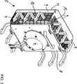
Vorzugsweise weist die Lüftereinheit eine im Wesentlichen quadratische Lüfterbox auf, in der der Radiallüfter aufgenommen ist, wobei die Lüfterbox an mindestens einer von vier parallel zu der Hauptströmungsrichtung und parallel zu einer Drehachse des Radiallüfters ausgerichteten Seiten einen Luftauslass aufweist.The fan unit preferably has a substantially square fan box in which the radial fan is accommodated, the fan box having an air outlet on at least one of four sides aligned parallel to the main flow direction and parallel to a rotation axis of the radial fan.
Bei dieser Ausführungsform kann weiterhin vorgesehen sein, dass die Luftleitgeometrie an den Luftauslass oder die Luftauslässe der Lüfterbox angrenzt und den Luftauslass oder die Luftauslässe von einer Saugseite des Radiallüfters fluidisch abgrenzt, so dass die aus dem Luftauslass oder den Luftauslässen austretende Luft von der Saugseite des Radiallüfters weggeführt wird.In this embodiment, it may further be provided that the Luftleitgeometrie adjacent to the air outlet or the air outlets of the fan box and fluidly delimits the air outlet or the air outlets from a suction side of the radial fan, so that the exiting from the air outlet or the air outlets from the suction side of the radial fan is led away.
Bei einer Ausführungsform der Erfindung, bei welcher die Lüfterbox im Wesentlichen quadratisch ist und an jeder der vier parallel zu der Hauptströmungsrichtung ausgerichteten Seiten der Lüfterbox ein Luftauslass ausgebildet ist, kann vorgesehen sein, dass die Luftleitgeometrie als ein Trichter, der um die vier parallel zu der Hauptströmungsrichtung ausgerichteten Seiten herum angeordnet ist, ausgebildet ist. Anstelle eines geschlossenen, rotationssymmetrischen Trichters, kann auch ein Teiltrichter vorgesehen sein, so dass dem Luftauslass als Luftleitgeometrie ein Trichtersegment zugeordnet ist.In an embodiment of the invention in which the fan box is substantially square and an air outlet is formed on each of the four sides of the fan box aligned parallel to the main flow direction, it may be provided that the air guide geometry is a funnel parallel to the four Main flow direction aligned sides is arranged around, is formed. Instead of a closed, rotationally symmetrical funnel, a part funnel can also be provided, so that a funnel segment is assigned to the air outlet as the air guide geometry.
Bei der bevorzugten Ausführungsform weist die Luftleitgeometrie im Querschnitt eine 90°-Krümmung auf. Im einfachsten Fall weist die Luftleitgeometrie einen ersten Abschnitt auf, der sich im Wesentlichen senkrecht zu zumindest einer von den vier parallel zu der Hauptströmungsrichtung ausgerichteten Seiten erstreckt und über die die Luftleitgeometrie mit der Lüfterbox in Verbindung steht. Zweckmäßigerweise ist dieser Abschnitt in Hauptströmungsrichtung zwischen der Saugseite der Lüfterbox und den Luftauslässen mit der Lüfterbox verbunden. Dieser erste Abschnitt kann in einem möglichst großen Radius in einen zweiten Abschnitt übergehen, der senkrecht zu dem ersten Abschnitt ausgerichtet ist. Der Radius sollte so groß wie möglich sein, um den Druckverlust so gering wie möglich zu halten. Andererseits wird der maximale Umlenkradius durch die im Inneren des Kühlgeräts vorhandenen Platzverhältnisse vorgegeben sein. Der Umlenkradius kann jedoch auch im Verlauf der Luftleitgeometrie variieren.In the preferred embodiment, the Luftleitgeometrie in cross section to a 90 ° curvature. In the simplest case, the air conduction geometry has a first section which extends substantially perpendicular to at least one of the four sides aligned parallel to the main flow direction and via which the air conduction geometry communicates with the ventilator box. Conveniently, this section is connected in the main flow direction between the suction side of the fan box and the air outlets with the fan box. This first section can be as large as possible Radius in a second section, which is aligned perpendicular to the first section. The radius should be as large as possible to keep the pressure loss as low as possible. On the other hand, the maximum deflection radius will be dictated by the available space inside the refrigerator. However, the deflection radius can also vary in the course of Luftleitgeometrie.
Bei einer Ausführungsform der Erfindung weist das Kühlgerät eine Mehrzahl der Lüftereinheiten auf, wobei benachbarte Lüftereinheiten derart zueinander vermittelt angeordnet sind, dass sie entlang ihrer jeweiligen Luftleitgeometrie zumindest abschnittsweise aneinander grenzen. Üblicherweise sind die Lüftereinheiten an der Luftauslassseite des Kühlgeräts in vertikaler Richtung aneinander gereiht. Vorzugsweise grenzen die Luftleitgeometrie benachbarter Lüftereinheiten entlang ihrer freien Enden aneinander um einen weitestgehend homogenen und gleichgerichteten Luftstrom an der Luftauslassseite zu erreichen.In one embodiment of the invention, the cooling device has a plurality of fan units, wherein adjacent fan units are arranged such that they adjoin one another at least in sections along their respective air guide geometry. Usually, the fan units on the air outlet side of the refrigerator in the vertical direction are lined up. The air conduction geometry of adjacent fan units preferably adjoin one another along their free ends in order to achieve a largely homogenous and rectified air flow at the air outlet side.
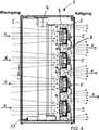
Bei einer weiteren Ausführungsform der Erfindung ist vorgesehen, dass bei benachbarten Lüftereinheiten ein Trennelement, das sich zwischen gegenüberliegenden Seiten der benachbarten Lüftereinheiten erstreckt, die Luftauslässe der benachbarten Lüftereinheiten von den Saugseiten der benachbarten Lüftereinheiten fluidisch dicht abtrennt. Auf diese Weise wird eine effektive Abschottung der gemeinsamen Ansaugseite von der gemeinsamen Ausblassseite der Lüftereinheiten erreicht.In a further embodiment of the invention, it is provided that in adjacent fan units, a separating element which extends between opposite sides of the adjacent fan units, the air outlets of the adjacent fan units fluidly sealed from the suction sides of the adjacent fan units. In this way, an effective foreclosure of the common intake side is achieved by the common exhaust side of the fan units.
Es kann weiterhin vorgesehen sein, dass das Kühlgerät ein Rahmengestell aufweist, wobei das Rahmengestell an der Luftauslassseite eine Einbauöffnung mit einer horizontalen Weite aufweist, die kleiner als eine horizontale Weite der Lüftereinheiten ist, oder die der horizontalen Weite der Lüftereinheiten entspricht, wobei die Lüftereinheiten in vertikaler Richtung übereinander an dem Rahmengestell montiert sind, und wobei sich das Trennelement über die gesamte horizontale Weite des Kühlgeräts erstreckt.It may further be provided that the cooling unit has a frame, wherein the frame on the air outlet side has a mounting opening with a horizontal width which is smaller than a horizontal width of the fan units, or corresponding to the horizontal width of the fan units, wherein the fan units in vertical direction are mounted one above the other on the frame, and wherein the separating element extends over the entire horizontal width of the cooling device.
Weitere Einzelheiten der Erfindung werden anhand der nachstehenden Figuren erläutert.Further details of the invention will be explained with reference to the following figures.
Dabei zeigt:Showing:
Die Luftleitgeometrie
Die
Die in der vorstehenden Beschreibung, in den Zeichnungen sowie in den Ansprüchen offenbarten Merkmale der Erfindung können sowohl einzeln als auch in beliebiger Kombination für die Verwirklichung der Erfindung wesentlich sein.The features of the invention disclosed in the foregoing description, in the drawings and in the claims may be essential to the realization of the invention both individually and in any combination.
BezugszeichenlisteLIST OF REFERENCE NUMBERS
- 11
- Kühlgerätcooling unit
- 22
- LufteinlassseiteAir intake side
- 33
- Luftauslassseiteair outlet
- 44
- Wärmetauscherheat exchangers
- 55
- Lüftereinheitfan unit
- 66
- Radiallüfterradial fans
- 77
- LuftleitgeometrieLuftleitgeometrie
- 88th
- Lüfterboxfan box
- 99
- Seite der LüfterboxSide of the fan box
- 1010
- Luftauslassair outlet
- 1111
- Saugseitesuction
- 1212
- Trennelementseparating element
- 1313
- Rahmengestellframe
- 2020
- Schaltschränkecabinets
- xx
- HauptströmungsrichtungMain flow direction
- yy
- Drehachse des RadiallüftersRotary axis of the radial fan
ZITATE ENTHALTEN IN DER BESCHREIBUNG QUOTES INCLUDE IN THE DESCRIPTION
Diese Liste der vom Anmelder aufgeführten Dokumente wurde automatisiert erzeugt und ist ausschließlich zur besseren Information des Lesers aufgenommen. Die Liste ist nicht Bestandteil der deutschen Patent- bzw. Gebrauchsmusteranmeldung. Das DPMA übernimmt keinerlei Haftung für etwaige Fehler oder Auslassungen.This list of the documents listed by the applicant has been generated automatically and is included solely for the better information of the reader. The list is not part of the German patent or utility model application. The DPMA assumes no liability for any errors or omissions.
Zitierte PatentliteraturCited patent literature
- EP 2011/052932[0001]EP 2011/052932[0001]
Claims (9)
Translated fromGermanPriority Applications (5)
| Application Number | Priority Date | Filing Date | Title |
|---|---|---|---|
| DE102012007707.6ADE102012007707B4 (en) | 2012-04-19 | 2012-04-19 | Cooling unit for cabinet cooling |
| PCT/DE2013/000074WO2013156011A1 (en) | 2012-04-19 | 2013-02-08 | Cooling apparatus for control cabinet cooling |
| EP13708340.8AEP2839724B1 (en) | 2012-04-19 | 2013-02-08 | Cooling apparatus for control cabinet cooling |
| CN201380026251.0ACN104335690B (en) | 2012-04-19 | 2013-02-08 | Cooling device for cooling down switch cubicle |
| US13/261,974US9883608B2 (en) | 2012-04-19 | 2013-02-08 | Cooling device for cooling a switchgear cabinet |
Applications Claiming Priority (1)
| Application Number | Priority Date | Filing Date | Title |
|---|---|---|---|
| DE102012007707.6ADE102012007707B4 (en) | 2012-04-19 | 2012-04-19 | Cooling unit for cabinet cooling |
Publications (2)
| Publication Number | Publication Date |
|---|---|
| DE102012007707A1true DE102012007707A1 (en) | 2013-10-24 |
| DE102012007707B4 DE102012007707B4 (en) | 2017-03-30 |
Family
ID=47844021
Family Applications (1)
| Application Number | Title | Priority Date | Filing Date |
|---|---|---|---|
| DE102012007707.6AExpired - Fee RelatedDE102012007707B4 (en) | 2012-04-19 | 2012-04-19 | Cooling unit for cabinet cooling |
Country Status (5)
| Country | Link |
|---|---|
| US (1) | US9883608B2 (en) |
| EP (1) | EP2839724B1 (en) |
| CN (1) | CN104335690B (en) |
| DE (1) | DE102012007707B4 (en) |
| WO (1) | WO2013156011A1 (en) |
Cited By (1)
| Publication number | Priority date | Publication date | Assignee | Title |
|---|---|---|---|---|
| DE102015105493B3 (en)* | 2015-04-10 | 2016-08-04 | Rittal Gmbh & Co. Kg | Control cabinet arrangement with a control cabinet row and a cooling unit arranged in it |
Families Citing this family (5)
| Publication number | Priority date | Publication date | Assignee | Title |
|---|---|---|---|---|
| DE102015105490B3 (en)* | 2015-04-10 | 2016-08-04 | Rittal Gmbh & Co. Kg | Cooling device for cooling the air taken in the interior of a cabinet and a corresponding control cabinet assembly |
| CN110701940B (en)* | 2019-10-28 | 2021-09-17 | 北京北方华创微电子装备有限公司 | Heat exchange device and semiconductor processing equipment |
| EP4167697A1 (en) | 2021-10-12 | 2023-04-19 | TOMRA Sorting GmbH | Cooling device for optical and/or electronic elements |
| DE202022002855U1 (en) | 2022-09-06 | 2023-10-06 | Rittal Gmbh & Co. Kg | Cooling device for control cabinet air conditioning |
| DE102022122580A1 (en) | 2022-09-06 | 2024-03-07 | Rittal Gmbh & Co. Kg | Cooling device for control cabinet air conditioning and a corresponding method |
Citations (5)
| Publication number | Priority date | Publication date | Assignee | Title |
|---|---|---|---|---|
| DE3028606A1 (en)* | 1980-07-28 | 1982-03-04 | Wilhelm Gebhardt Gmbh, 7112 Waldenburg | FOR INSTALLATION IN PIPELINES, CHANNELS OR CHANNEL-LIKE HOUSINGS OR. FAN UNIT DETERMINED IN VENTILATION AND AIR CONDITIONING |
| DE4021316A1 (en)* | 1989-07-25 | 1991-02-07 | Neuhaus Gerhard | Axial delivery fan for box-shaped housing - with provision of deflection plate to improve efficiency |
| DE19709193B4 (en)* | 1996-03-18 | 2007-03-29 | Industriventilation Produkt Ab | centrifugal fan |
| US7861543B2 (en)* | 2006-11-03 | 2011-01-04 | American Power Conversion Corporation | Water carryover avoidance method |
| WO2012116724A1 (en) | 2011-02-28 | 2012-09-07 | Rittal Gmbh & Co. Kg | Cooling device |
Family Cites Families (9)
| Publication number | Priority date | Publication date | Assignee | Title |
|---|---|---|---|---|
| US2912916A (en)* | 1958-12-26 | 1959-11-17 | Chelsea Products Inc | Ventilator devices |
| DE3826588A1 (en) | 1988-08-04 | 1990-02-08 | Schmitz Kuehler Baierbrunn | AIR COOLER |
| EP1019659B1 (en)* | 1997-09-03 | 2004-01-21 | Kyodo-Allied Industries Limited | A method and apparatus for minimising noise from fan filter unit |
| DE102005005296B3 (en) | 2005-02-04 | 2006-05-18 | Knürr AG | Cooling unit for electronic modules used in server, comprises a supply of cool air, an air-liquid heat exchanger, and ventilators |
| US20100091449A1 (en)* | 2006-06-01 | 2010-04-15 | Jimmy Clidaras | Modular Computing Environments |
| KR100782197B1 (en)* | 2006-08-03 | 2007-12-04 | 엘지전자 주식회사 | Air conditioner |
| WO2008039773A2 (en) | 2006-09-25 | 2008-04-03 | Rackable Systems, Inc. | Container-based data center |
| EP2220440B1 (en)* | 2007-11-21 | 2018-09-05 | Liebert Corporation | Computer room environmental conditioning unit with translatable blowers |
| US8072756B1 (en)* | 2010-05-28 | 2011-12-06 | Rockwell Automation Technologies, Inc. | Air cooling of medium voltage drive components |
- 2012
- 2012-04-19DEDE102012007707.6Apatent/DE102012007707B4/ennot_activeExpired - Fee Related
- 2013
- 2013-02-08EPEP13708340.8Apatent/EP2839724B1/enactiveActive
- 2013-02-08WOPCT/DE2013/000074patent/WO2013156011A1/enactiveApplication Filing
- 2013-02-08CNCN201380026251.0Apatent/CN104335690B/enactiveActive
- 2013-02-08USUS13/261,974patent/US9883608B2/enactiveActive
Patent Citations (5)
| Publication number | Priority date | Publication date | Assignee | Title |
|---|---|---|---|---|
| DE3028606A1 (en)* | 1980-07-28 | 1982-03-04 | Wilhelm Gebhardt Gmbh, 7112 Waldenburg | FOR INSTALLATION IN PIPELINES, CHANNELS OR CHANNEL-LIKE HOUSINGS OR. FAN UNIT DETERMINED IN VENTILATION AND AIR CONDITIONING |
| DE4021316A1 (en)* | 1989-07-25 | 1991-02-07 | Neuhaus Gerhard | Axial delivery fan for box-shaped housing - with provision of deflection plate to improve efficiency |
| DE19709193B4 (en)* | 1996-03-18 | 2007-03-29 | Industriventilation Produkt Ab | centrifugal fan |
| US7861543B2 (en)* | 2006-11-03 | 2011-01-04 | American Power Conversion Corporation | Water carryover avoidance method |
| WO2012116724A1 (en) | 2011-02-28 | 2012-09-07 | Rittal Gmbh & Co. Kg | Cooling device |
Cited By (3)
| Publication number | Priority date | Publication date | Assignee | Title |
|---|---|---|---|---|
| DE102015105493B3 (en)* | 2015-04-10 | 2016-08-04 | Rittal Gmbh & Co. Kg | Control cabinet arrangement with a control cabinet row and a cooling unit arranged in it |
| WO2016162014A1 (en) | 2015-04-10 | 2016-10-13 | Rittal Gmbh & Co. Kg | Electrical enclosure arrangement comprising an electrical enclosure line and a cooling device connected into the line |
| US11044831B2 (en) | 2015-04-10 | 2021-06-22 | Rittal Gmbh & Co. Kg | Electrical enclosure arrangement comprising an electrical enclosure line and a cooling device connected into the line |
Also Published As
| Publication number | Publication date |
|---|---|
| CN104335690B (en) | 2017-09-26 |
| CN104335690A (en) | 2015-02-04 |
| WO2013156011A1 (en) | 2013-10-24 |
| EP2839724B1 (en) | 2016-09-14 |
| US9883608B2 (en) | 2018-01-30 |
| DE102012007707B4 (en) | 2017-03-30 |
| EP2839724A1 (en) | 2015-02-25 |
| US20150156918A1 (en) | 2015-06-04 |
Similar Documents
| Publication | Publication Date | Title |
|---|---|---|
| EP2839724B1 (en) | Cooling apparatus for control cabinet cooling | |
| DE102015105493B3 (en) | Control cabinet arrangement with a control cabinet row and a cooling unit arranged in it | |
| DE102009054011B4 (en) | Cooling arrangement for arranged in a cabinet electrical equipment | |
| DE102015105490B3 (en) | Cooling device for cooling the air taken in the interior of a cabinet and a corresponding control cabinet assembly | |
| EP2278231B1 (en) | Air conditioning device | |
| EP3583668B1 (en) | Heat dissipation device for an electrical cabinet | |
| DE102009057129A1 (en) | Ventilation device for components of an electronic or computer cabinet | |
| WO2008055569A1 (en) | Climate control device | |
| DE202013103846U1 (en) | Filter fan arrangement for cooling a control cabinet | |
| DE102009030088B4 (en) | casing | |
| DE9200134U1 (en) | Cooling unit for control cabinets | |
| DE102011050323B3 (en) | Cooling device for data processing system, has pressure chamber which is separated by boundary wall from heat exchanger such that overpressure is obtained in pressure chamber in operation of fan assembly | |
| DE102014101453A1 (en) | Control cabinet with air conditioning device | |
| EP2285199B1 (en) | Modular device and component | |
| EP2410829B1 (en) | Cooling system for housed electronic equipment | |
| DE102020001435B4 (en) | Liquid-air cooling system | |
| EP2665350A2 (en) | Fan unit for cooling of apparatus, such as electrical/electronic assemblies, equipment and the like | |
| EP0890802B1 (en) | Exhaust and ventilation device with regenerative heat recovery | |
| WO2015180843A1 (en) | Air conditioning arrangement | |
| WO2015185124A1 (en) | Air deflector device | |
| DE102008012200A1 (en) | Heat exchanger has heat exchanger wall with heat absorbing side and heat dissipating side, where both sides are provided with channel covers, and flow channel is formed between channel cover and heat absorbing or dissipating side | |
| DE102012103056A1 (en) | Arrangement for cooling electrical components in switchgear cabinets in datacenter, has exhaust air duct connecting interior of cabinet with inner space, and refrigerator defining cold aisle in which cooled air flows from refrigerator | |
| DE202014104692U1 (en) | switch cabinet | |
| EP3248446B1 (en) | Cooling device | |
| DE102005009074A1 (en) | Air ventilation system, has ventilating units arranged such that heat exchange unit conducts high/low pressure produced by units, where air flow produced directly by units is discharged directly into flow channels via module ducts |
Legal Events
| Date | Code | Title | Description |
|---|---|---|---|
| R012 | Request for examination validly filed | ||
| R016 | Response to examination communication | ||
| R016 | Response to examination communication | ||
| R018 | Grant decision by examination section/examining division | ||
| R119 | Application deemed withdrawn, or ip right lapsed, due to non-payment of renewal fee |