DE102011122549A1 - Method for repairing an inlet layer of a compressor of a gas turbine - Google Patents
Method for repairing an inlet layer of a compressor of a gas turbineDownload PDFInfo
- Publication number
- DE102011122549A1 DE102011122549A1DE102011122549ADE102011122549ADE102011122549A1DE 102011122549 A1DE102011122549 A1DE 102011122549A1DE 102011122549 ADE102011122549 ADE 102011122549ADE 102011122549 ADE102011122549 ADE 102011122549ADE 102011122549 A1DE102011122549 A1DE 102011122549A1
- Authority
- DE
- Germany
- Prior art keywords
- repaired
- inlet layer
- area
- gas turbine
- repair medium
- Prior art date
- Legal status (The legal status is an assumption and is not a legal conclusion. Google has not performed a legal analysis and makes no representation as to the accuracy of the status listed.)
- Withdrawn
Links
Images


Classifications
- B—PERFORMING OPERATIONS; TRANSPORTING
- B23—MACHINE TOOLS; METAL-WORKING NOT OTHERWISE PROVIDED FOR
- B23P—METAL-WORKING NOT OTHERWISE PROVIDED FOR; COMBINED OPERATIONS; UNIVERSAL MACHINE TOOLS
- B23P6/00—Restoring or reconditioning objects
- B23P6/002—Repairing turbine components, e.g. moving or stationary blades, rotors
- B—PERFORMING OPERATIONS; TRANSPORTING
- B05—SPRAYING OR ATOMISING IN GENERAL; APPLYING FLUENT MATERIALS TO SURFACES, IN GENERAL
- B05B—SPRAYING APPARATUS; ATOMISING APPARATUS; NOZZLES
- B05B13/00—Machines or plants for applying liquids or other fluent materials to surfaces of objects or other work by spraying, not covered by groups B05B1/00 - B05B11/00
- B05B13/06—Machines or plants for applying liquids or other fluent materials to surfaces of objects or other work by spraying, not covered by groups B05B1/00 - B05B11/00 specially designed for treating the inside of hollow bodies
- B—PERFORMING OPERATIONS; TRANSPORTING
- B05—SPRAYING OR ATOMISING IN GENERAL; APPLYING FLUENT MATERIALS TO SURFACES, IN GENERAL
- B05B—SPRAYING APPARATUS; ATOMISING APPARATUS; NOZZLES
- B05B7/00—Spraying apparatus for discharge of liquids or other fluent materials from two or more sources, e.g. of liquid and air, of powder and gas
- B05B7/14—Spraying apparatus for discharge of liquids or other fluent materials from two or more sources, e.g. of liquid and air, of powder and gas designed for spraying particulate materials
- B05B7/1481—Spray pistols or apparatus for discharging particulate material
- B05B7/1486—Spray pistols or apparatus for discharging particulate material for spraying particulate material in dry state
- F—MECHANICAL ENGINEERING; LIGHTING; HEATING; WEAPONS; BLASTING
- F01—MACHINES OR ENGINES IN GENERAL; ENGINE PLANTS IN GENERAL; STEAM ENGINES
- F01D—NON-POSITIVE DISPLACEMENT MACHINES OR ENGINES, e.g. STEAM TURBINES
- F01D21/00—Shutting-down of machines or engines, e.g. in emergency; Regulating, controlling, or safety means not otherwise provided for
- F01D21/003—Arrangements for testing or measuring
- F—MECHANICAL ENGINEERING; LIGHTING; HEATING; WEAPONS; BLASTING
- F01—MACHINES OR ENGINES IN GENERAL; ENGINE PLANTS IN GENERAL; STEAM ENGINES
- F01D—NON-POSITIVE DISPLACEMENT MACHINES OR ENGINES, e.g. STEAM TURBINES
- F01D5/00—Blades; Blade-carrying members; Heating, heat-insulating, cooling or antivibration means on the blades or the members
- F01D5/005—Repairing methods or devices
- F—MECHANICAL ENGINEERING; LIGHTING; HEATING; WEAPONS; BLASTING
- F02—COMBUSTION ENGINES; HOT-GAS OR COMBUSTION-PRODUCT ENGINE PLANTS
- F02C—GAS-TURBINE PLANTS; AIR INTAKES FOR JET-PROPULSION PLANTS; CONTROLLING FUEL SUPPLY IN AIR-BREATHING JET-PROPULSION PLANTS
- F02C7/00—Features, components parts, details or accessories, not provided for in, or of interest apart form groups F02C1/00 - F02C6/00; Air intakes for jet-propulsion plants
- F—MECHANICAL ENGINEERING; LIGHTING; HEATING; WEAPONS; BLASTING
- F05—INDEXING SCHEMES RELATING TO ENGINES OR PUMPS IN VARIOUS SUBCLASSES OF CLASSES F01-F04
- F05B—INDEXING SCHEME RELATING TO WIND, SPRING, WEIGHT, INERTIA OR LIKE MOTORS, TO MACHINES OR ENGINES FOR LIQUIDS COVERED BY SUBCLASSES F03B, F03D AND F03G
- F05B2230/00—Manufacture
- F05B2230/80—Repairing, retrofitting or upgrading methods
- F—MECHANICAL ENGINEERING; LIGHTING; HEATING; WEAPONS; BLASTING
- F05—INDEXING SCHEMES RELATING TO ENGINES OR PUMPS IN VARIOUS SUBCLASSES OF CLASSES F01-F04
- F05B—INDEXING SCHEME RELATING TO WIND, SPRING, WEIGHT, INERTIA OR LIKE MOTORS, TO MACHINES OR ENGINES FOR LIQUIDS COVERED BY SUBCLASSES F03B, F03D AND F03G
- F05B2230/00—Manufacture
- F05B2230/90—Coating; Surface treatment
- F—MECHANICAL ENGINEERING; LIGHTING; HEATING; WEAPONS; BLASTING
- F05—INDEXING SCHEMES RELATING TO ENGINES OR PUMPS IN VARIOUS SUBCLASSES OF CLASSES F01-F04
- F05D—INDEXING SCHEME FOR ASPECTS RELATING TO NON-POSITIVE-DISPLACEMENT MACHINES OR ENGINES, GAS-TURBINES OR JET-PROPULSION PLANTS
- F05D2220/00—Application
- F05D2220/30—Application in turbines
- F05D2220/32—Application in turbines in gas turbines
- F05D2220/323—Application in turbines in gas turbines for aircraft propulsion, e.g. jet engines
- F—MECHANICAL ENGINEERING; LIGHTING; HEATING; WEAPONS; BLASTING
- F05—INDEXING SCHEMES RELATING TO ENGINES OR PUMPS IN VARIOUS SUBCLASSES OF CLASSES F01-F04
- F05D—INDEXING SCHEME FOR ASPECTS RELATING TO NON-POSITIVE-DISPLACEMENT MACHINES OR ENGINES, GAS-TURBINES OR JET-PROPULSION PLANTS
- F05D2230/00—Manufacture
- F05D2230/80—Repairing, retrofitting or upgrading methods
- F—MECHANICAL ENGINEERING; LIGHTING; HEATING; WEAPONS; BLASTING
- F05—INDEXING SCHEMES RELATING TO ENGINES OR PUMPS IN VARIOUS SUBCLASSES OF CLASSES F01-F04
- F05D—INDEXING SCHEME FOR ASPECTS RELATING TO NON-POSITIVE-DISPLACEMENT MACHINES OR ENGINES, GAS-TURBINES OR JET-PROPULSION PLANTS
- F05D2230/00—Manufacture
- F05D2230/90—Coating; Surface treatment
- Y—GENERAL TAGGING OF NEW TECHNOLOGICAL DEVELOPMENTS; GENERAL TAGGING OF CROSS-SECTIONAL TECHNOLOGIES SPANNING OVER SEVERAL SECTIONS OF THE IPC; TECHNICAL SUBJECTS COVERED BY FORMER USPC CROSS-REFERENCE ART COLLECTIONS [XRACs] AND DIGESTS
- Y10—TECHNICAL SUBJECTS COVERED BY FORMER USPC
- Y10T—TECHNICAL SUBJECTS COVERED BY FORMER US CLASSIFICATION
- Y10T29/00—Metal working
- Y10T29/49—Method of mechanical manufacture
- Y10T29/49229—Prime mover or fluid pump making
- Y10T29/49236—Fluid pump or compressor making
- Y10T29/49238—Repairing, converting, servicing or salvaging
Landscapes
- Engineering & Computer Science (AREA)
- Mechanical Engineering (AREA)
- General Engineering & Computer Science (AREA)
- Chemical & Material Sciences (AREA)
- Combustion & Propulsion (AREA)
- Structures Of Non-Positive Displacement Pumps (AREA)
Abstract
Translated fromGermanDescription
Translated fromGermanDie Erfindung bezieht sich auf Verfahren zur Reparatur einer Einlaufschicht eines Verdichters einer Gasturbine, bei welchem zumindest ein verschlissener Bereich der Einlaufschicht im nicht-demontierten Zustand der Gasturbine repariert wird.The invention relates to methods for repairing an inlet layer of a compressor of a gas turbine, wherein at least a worn portion of the inlet layer is repaired in the non-disassembled state of the gas turbine.
Einlaufschichten für Verdichterbeschaufelungen in Flugzeugtriebwerken oder in stationären Gasturbinen sind weiche Schichten, die ein Einlaufen der Verdichterbeschaufelung in die statische oder sich drehende härtere Gegenseite sicherstellen soll. Es werden im Wesentlichen Al-Si-Polyester, Al-Si-Graphit, Ni-Graphit oder Aluminiumoxid Beschichtungen verwendet. Damit erreicht man ein möglichst kleines Spitzenspiel und somit einen guten Verdichterwirkungsgrad. Während des Betriebes eines Triebwerks verschleißen die Einlaufschichten entweder komplett über den gesamten Umfang oder auch nur partiell. Dies führt zu einem Leistungsverlust des Triebwerks, verursacht durch eine Verschlechterung des Verdichterwirkungsgrades und zu Schwingungen, die wiederum die Verdichterbeschaufelung zu unkontrollierten Schwingungen und letztendlich auch zu Rissen an Triebwerksschaufeln anregen. Aus diesen Gründen müssen die Einlaufschichten im Rahmen einer Reparaturmaßnahme wieder in einen ordnungsgemäßen Zustand gebracht werden.Intake layers for compressor thrusters in aircraft engines or in stationary gas turbines are soft layers intended to ensure that the compressor blades run into the static or rotating harder opposite side. Essentially Al-Si-polyester, Al-Si-graphite, Ni-graphite or alumina coatings are used. This achieves the smallest possible top clearance and thus a good compressor efficiency. During operation of an engine, the inlet layers wear either completely over the entire circumference or only partially. This results in a power loss of the engine caused by a deterioration of the compressor efficiency and vibrations, which in turn stimulate the compressor blade to uncontrolled vibrations and ultimately to cracks on engine blades. For these reasons, the run-in layers must be returned to a proper condition as part of a repair measure.
Für die Durchführung der Reparatur muss nach dem Stand der Technik das Triebwerk aus dem Luftfahrzeug ausgebaut und in dafür vorgesehene und autorisierte Werkstätten überführt werden. Diese Werkstätten benötigen eine Ausstattung, die denen der Neuteilfertigungseinrichtungen entsprechen. Darüber hinaus muss das Luftfahrzeug während der Zeitdauer der Triebwerksinstandsetzung mit einem Ersatztriebwerk ausgerüstet werden.To carry out the repair, the engine has to be removed from the aircraft according to the state of the art and transferred to authorized and authorized workshops. These workshops need equipment that matches those of the new parts production facilities. In addition, the aircraft must be equipped with a replacement engine during the period of engine repair.
Der Erfindung liegt die Aufgabe zugrunde, ein Reparaturverfahren der eingangs genannten Art zu schaffen, welches bei einfacher Durchführung eine kostengünstige Reparatur ermöglicht.The invention has for its object to provide a repair method of the type mentioned, which allows a simple implementation of a cost repair.
Erfindungsgemäß wird die Aufgabe durch die Merkmalskombination des Anspruchs 1 gelöst, die Unteransprüche zeigen weitere vorteilhafte Ausgestaltungen der Erfindung.According to the invention the object is achieved by the combination of features of
Erfindungsgemäß ist somit vorgesehen, dass eine verschlissene Einlaufschicht im nicht-demontierten Zustand der Gasturbine repariert wird. Dabei wird zunächst mittels eines Boroskops im nicht-demontierten Zustand eine Analyse und/oder Auswahl von zu reparierenden Bereichen der Einlaufschicht durchgeführt, wobei nachfolgend durch zumindest eine Boroskopie-Öffnung ein Werkzeug an den oder die zu reparierenden Bereiche gebracht und die Bereiche der verschlissenen Einlaufschicht, welche repariert werden sollen, zumindest zum Teil abgetragen werden. Das abgetragene Material wird dabei erfindungsgemäß abgesaugt, um zu verhindern, dass das Material sich unkontrolliert in der Gasturbine verteilt. Nachfolgend wird erfindungsgemäß der zu reparierende Bereich der Verschleißschicht zur Aufbringung eines Reparaturmediums gereinigt und/der präpariert, insbesondere, um die Haftung des Reparaturmediums zu verbessern. Nachfolgend wird ein aushärtbares Reparaturmedium auf dem zu reparierenden Bereich aufgebracht und nachfolgend ausgehärtet, wobei ein aushärtbares, auf Aluminiumoxid basierendes Reparaturmedium auf den zu reparierenden Bereich mittels einer Art Luftdruckbürste aufgebracht und nachfolgend ausgehärtet wird und wobei nachfolgend der mit dem Reparaturmedium versehene Bereich mechanisch bearbeitet wird.The invention thus provides that a worn inlet layer is repaired in the non-disassembled state of the gas turbine. In this case, an analysis and / or selection of areas of the inlet layer to be repaired is first carried out by means of a borescope in the non-disassembled state, wherein subsequently a tool is brought to the area or areas to be repaired by at least one boroscopy opening and the areas of the worn inlet layer, which are to be repaired, at least partially removed. The removed material is sucked off according to the invention, in order to prevent the material from being distributed uncontrollably in the gas turbine. Subsequently, according to the invention, the area of the wear layer to be repaired for the application of a repair medium is cleaned and / or prepared, in particular in order to improve the adhesion of the repair medium. Subsequently, a curable repair medium is applied to the area to be repaired and subsequently cured, wherein a curable, alumina-based repair medium is applied to the area to be repaired by means of a kind of airbrush and subsequently cured and subsequently the area provided with the repair medium is mechanically processed.
Besonders günstig ist es, wenn der zu reparierende Bereich vor der Aufbringung des Reparaturmediums gereinigt wird, dies kann beispielsweise mittels einer Reinigungsflüssigkeit und einer nachfolgenden Trocknung in bevorzugter Weise erfolgen.It is particularly favorable if the area to be repaired is cleaned prior to the application of the repair medium; this can be done, for example, by means of a cleaning liquid and subsequent drying in a preferred manner.
Um eine gute Zugänglichkeit und eine verbesserte Reparaturmöglichkeit zu schaffen, ist es besonders günstig, wenn der zu reparierende Bereich eines Rotors der Gasturbine bei horizontaler Anordnung einer Maschinenachse oben liegend angeordnet wird.In order to provide good accessibility and an improved repair possibility, it is particularly favorable if the area of a rotor of the gas turbine to be repaired is arranged lying on top when a machine axis is arranged horizontally.
Das Reparaturmedium besteht aus einem Aluminiumoxid, welches im ausgehärteten Zustand einen ähnlichen Wärmeausdehnungskoeffizienten sowie eine ähnliche Härte und Porosität wie die ursprüngliche Beschichtung besitzt. Die Viskosität des Reparaturmediums kann durch das Untermischen eines Verdünners angepasst werden. Das Reparaturmedium wird durch einen Schlauch zugeführt, welcher in einem Boroskop integriert werden kann. Das Applizieren kann mittels einer Luftdruckbürste durchgeführt werden. Erfindungsgemäß wird das Reparaturmedium in bevorzugter Gestaltung der Erfindung mehrlagig aufgebracht. Die Bestimmung der Schichtdicke geschieht hierbei bevorzugter weise halbautomatisch durch die Steuerung der aufgetragenen Menge an Reparaturmedium für den jeweiligen Beschichtungsabschnitt. Das Aushärten geschieht bevorzugterweise automatisch unter Luft durch das Einwirken von Wärme.The repair medium consists of an aluminum oxide, which in the cured state has a similar coefficient of thermal expansion and a hardness and porosity similar to the original coating. The viscosity of the repair medium can be adjusted by mixing in a diluent. The repair medium is supplied through a hose, which can be integrated in a borescope. The application can be carried out by means of an air pressure brush. According to the invention, the repair medium is applied in multiple layers in a preferred embodiment of the invention. The determination of the layer thickness is done here preferably semi-automatically by controlling the applied amount of repair medium for the respective coating section. The curing is preferably done automatically under air by the action of heat.
Um die Demontage einer Gasturbine zu ersparen, werden Sichtkontrollen mit einem Boroskop durchgeführt. Dieses dünne Rohr, das seinen Ursprung in der medizinischen Endoskopie hat, ist im Inneren mit einer Linsenoptik ausgestattet, die in einen zu untersuchenden Hohlraum eingeführt werden kann. Lichtleiterfasern umschließen die Optik und bringen das Licht aus einer angeschlossenen Quelle zum Ort der Inspektion, von wo ein reflektiertes Bild durch die Optik zurück zum Auge des Betrachters oder in eine Kamera mit angeschlossenem Bildschirm gelangt. So liefert die Boroskopie Bilder von Orten, die ohne die Demontage größerer Bauteile niemals zugänglich wären.To save the dismantling of a gas turbine, visual inspections are carried out with a borescope. This thin tube, which has its origin in medical endoscopy, is internally equipped with a lens optic that can be inserted into a cavity to be examined. Fiber optic fibers enclose the optics and bring the light from an attached source to the site of inspection, from where a reflected Picture through the optics back to the eye of the beholder or into a camera with a connected screen. The boroscopy provides images of places that would never be accessible without the dismantling of larger components.
Ein Flugtriebwerk besitzt für die Boroskopie-Untersuchung eine Vielzahl spezieller Öffnungen, die es ermöglichen, die Optik direkt an die zu untersuchende Stelle zu führen, beispielsweise in jede einzelne Verdichterstufe. Für Letztere reicht eine einzige Öffnung, weil die zu untersuchenden Schaufeln per Hand vor die Optik des Boroskops gedreht werden können. Starre Bauteile ohne direkten Zugang werden mit einem Flexoskop inspiziert. Anstelle des starren Rohrs besitzt dieses Werkzeug einen biegsamen Schlauch, in dem Glasfasern die Linsenoptik ersetzen. Mit einer Arbeitslänge von mehreren Metern können damit auch Bauteile inspiziert werden, die nicht auf geradem Weg zu erreichen sind.An aircraft engine has a variety of special openings for the boroscopy examination, which make it possible to guide the optics directly to the location to be examined, for example in each individual compressor stage. For the latter, a single opening is sufficient because the blades to be examined can be manually turned in front of the optics of the borescope. Rigid components without direct access are inspected with a flexoscope. Instead of the rigid tube, this tool has a flexible tube in which glass fibers replace the lens optics. With a working length of several meters, it is also possible to inspect components that can not be reached by a straight path.
Mit der Erfindung wird somit ermöglicht, die Reparatur der Einlaufschichten auszuführen, ohne das Triebwerk vom Luftfahrzeug abzubauen. Bei stationären Gasturbinen wird die Ausfallzeit drastisch reduziert. Hierfür werden über an dem Triebwerk befindliche Boroskop-Öffnungen miniaturisierte Werkzeuge dem Reparaturbereich zugeführt. Mit Hilfe eines Mikrofräsers in Verbindung mit einer Absaugvorrichtung wird der betroffene Bereich bearbeitet. Der zu reparierende Bereich wird so präpariert, dass gute Voraussetzungen für die Haftung des Reparaturmediums gegeben sind. Zusätzlich kann dies durch das gezielte Strahlen mit spezieller Reinigungsflüssigkeit und anschließender Trocknung mit sauberer Luft unterstützt werden. Beides (Reinigungsflüssigkeit und Druckluft) wird mit einem Boroskop zugeführt.The invention thus makes it possible to carry out the repair of the inlet layers without removing the engine from the aircraft. With stationary gas turbines the downtime is drastically reduced. For this purpose miniaturized tools are supplied to the repair area via Boroskop openings located on the engine. With the aid of a microfreaker in conjunction with a suction device, the affected area is processed. The area to be repaired is prepared so that good conditions for the adhesion of the repair medium are given. In addition, this can be supported by the targeted blasting with special cleaning fluid and subsequent drying with clean air. Both (cleaning fluid and compressed air) is supplied with a borescope.
Nach der Vorbereitung des Reparaturbereichs kann das Reparaturmedium, welches aus Aluminiumoxid Partikeln besteht, aufgebracht werden. Das Aufbringen erfolgt mittels einer Luftdruckbürste. Das Reparaturmedium und die Druckluft werden in zwei getrennten Leitungen an der Hinterseite vom Werkzeug zugeführt und im Werkzeug vermischt. Die Druckluftmenge wird durch ein Ventil geregelt. Die Zufuhr des Reparaturmediums wird über eine Nadel, die den Strömungsquerschnitt der Düse variiert, geregelt. Gegebenenfalls wird die Nadel mit Ultraschall angeregt, um ein Verstopfen der Düse zu verhindern.After the repair area has been prepared, the repair medium, which consists of aluminum oxide particles, can be applied. The application is carried out by means of an air pressure brush. The repair medium and the compressed air are supplied in two separate lines at the back of the tool and mixed in the tool. The amount of compressed air is controlled by a valve. The supply of the repair medium is controlled by a needle which varies the flow cross-section of the nozzle. If necessary, the needle is excited with ultrasound to prevent clogging of the nozzle.
Der axiale Abstand von der Düse zu der zu beschichtenden Fläche kann durch Verschieben der Führungsbuchse eingestellt werden. Die Düse ist um einige Grad gegenüber der Rotationsachse des Werkzeugs abgewinkelt. Durch eine Rotation vom Werkzeug um die Rotationsachse kann der Strahl gelenkt werden, hierdurch kann der Sprühbereich erweitert und die Auftragsgenauigkeit erhöht werden. Das Strahlbild ist abhängig von der Druckluft, dem Nadelstand und auch von der Geometrie der Düse. Besonders günstig ist es, wenn die Düse austauschbar ist und somit unterschiedliche Düsengeometrien angebracht werden können. Um den geometrischen Anforderungen verschiedener Verdichterstufen gerecht zu werden, werden gegebenenfalls mehrere Werkzeuge benötigt.The axial distance from the nozzle to the surface to be coated can be adjusted by moving the guide bushing. The nozzle is angled a few degrees from the axis of rotation of the tool. By a rotation of the tool about the axis of rotation of the beam can be steered, thereby the spray range can be extended and the order accuracy can be increased. The spray pattern depends on the compressed air, the needle position and also on the geometry of the nozzle. It is particularly favorable when the nozzle is replaceable and thus different nozzle geometries can be attached. To meet the geometric requirements of different compressor stages, several tools may be needed.
Das Aufbringen erfolgt in mehreren Lagen. Der Rotor kann während der Reparatur mit einer genau regelbaren Geschwindigkeit rotiert werden. So ist es möglich, den Rotor über den gesamten Umfang zu beschichten. Der mehrlagige Aufbau hat den Vorteil, dass der Reparaturbereich endkonturnah wieder hergestellt werden kann, was den Aufwand für eine anschließende mechanische Nacharbeit auf ein Minimum reduziert. Außerdem wird bei dünnen Schichten Tropfenbildung verhindert und es können auch senkrechte Flächen beschichtet werden. Weitere Schichten können in kurzen Intervallen aufgebracht werden.The application takes place in several layers. The rotor can be rotated during the repair with a precisely adjustable speed. So it is possible to coat the rotor over the entire circumference. The multi-layer structure has the advantage that the repair area can be restored close to the final contour, which reduces the expenditure for a subsequent mechanical reworking to a minimum. In addition, with thin layers, droplet formation is prevented and even vertical surfaces can be coated. Additional layers can be applied at short intervals.
Das Reparaturmedium soll nach dem Beschichten durch moderate Wärmezufuhr (Elektrisch, Gebläse oder Mikrobrenner) ausgehärtet werden. Nach dem Aushärten hat sich eine homogene Beschichtung gebildet. Gegebenenfalls müssen noch Ablagerungen in der Nähe des reparierten Bereichs entfernt werden.The repair medium should be cured after coating by moderate heat (electric, blower or micro burner). After curing, a homogeneous coating has formed. If necessary, deposits in the vicinity of the repaired area must be removed.
Mittels des erfindungsgemäßen Verfahrens ist es somit möglich, teure Demontagen von Flugzeugtriebwerken zu vermeiden, insbesondere den Austausch eines Triebwerks gegen ein Ersatztriebwerk zu vermeiden, so wie dies nach dem Stand der Technik bei derartigen Reparaturarbeiten erforderlich ist. Es ergeben sich hierdurch ganz erhebliche Vorteile durch die verringerten Arbeitszeiten und durch die sich ergebende Kostenersparnis.By means of the method according to the invention it is thus possible to avoid expensive disassembly of aircraft engines, in particular to avoid the replacement of an engine with a replacement engine, as is required by the prior art in such repairs. This results in quite considerable advantages due to the reduced working hours and the resulting cost savings.
Im Folgenden wird die Erfindung anhand eines Ausführungsbeispiels in Verbindung der Zeichnung beschrieben. Dabei zeigt:In the following the invention will be described with reference to an embodiment in conjunction with the drawing. Showing:
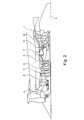
Die
Das erfindungsgemäße Reparaturverfahren erfolgt unter Verwendung zumindest eines Boroskops, welches durch geeignete Öffnungen des Gehäuses in den Bereich der Schaufeln
Die
In
- A
Hochdruckverdichterlaufschaufeln Stufe 1, Eintrittskante B Hochdruckverdichterlaufschaufeln Stufe 1,Austrittskante Hochdruckverdichterlaufschaufeln Stufe 2, EintrittskanteC Hochdruckverdichterlaufschaufeln Stufe 3,Austrittskante Hochdruckverdichterlaufschaufeln Stufe 4, EintrittskanteD Hochdruckverdichterlaufschaufeln Stufe 5,Austrittskante Hochdruckverdichterlaufschaufeln Stufe 6, Eintrittskante- E Hochdruckverdichterlaufschaufeln Stufe 9, Austrittskante Hochdruckverdichterlaufschaufeln Stufe 10, Eintrittskante
F Hochdruckturbinenlaufschaufeln Stufe 1,Eintrittskante Hochdruckturbinenleitschaufeln Stufe 1, BrennkammerG Hochdruckturbinenlaufschaufeln Stufe 1,Austrittskante Hochdruckturbinenlaufschaufeln Stufe 2, EintrittskanteH Hochdruckturbinenlaufschaufeln Stufe 2,Austrittskante Niederdruckturbinenlaufschaufeln Stufe 1, EintrittskanteI Niederdruckturbinenlaufschaufein Stufe 2, Austrittskante
- A high pressure
compressor blades stage 1, leading edge - B High-pressure
compressor blades Level 1, outlet edge High-pressurecompressor blades Stage 2, leading edge - C high-pressure
compressor blades stage 3, outlet edge high-pressurecompressor blades stage 4, leading edge - D High-pressure
compressor blades Level 5, outlet edge High-pressurecompressor blades Stage 6, leading edge - E high pressure compressor blades stage 9, outlet edge high pressure compressor blades stage 10, leading edge
- F high pressure
turbine blades stage 1, leading edge high pressure turbinestator blades stage 1, combustion chamber - G High Pressure
Turbine Blades Stage 1, High Pressure Turbine BladesRun Out Stage 2, Leading Edge - H high-pressure turbine blades,
stage 2, low-pressure turbine rotor outlet blades,stage 1, leading edge - I low pressure turbine rotor in
stage 2, trailing edge
Die
Der Manipulator
Es versteht sich, dass die Darstellung der
Die
An der Vorderseite des Werkzeugs
Die
Die
Die
Die
BezugszeichenlisteLIST OF REFERENCE NUMBERS
- 11
- Einlaufschicht des VerdichtergehäusesInlet layer of the compressor housing
- 22
- Einlaufschicht des RotorsInlet layer of the rotor
- 33
- Maschinenachsemachine axis
- 44
- Verdichtergehäusecompressor housing
- 55
- Rotor/VerdichtertrommelRotor / compressor drum
- 66
- Rotorschaufelrotor blade
- 77
- Statorstator
- 1111
- Gehäusecasing
- 1212
- Zugangsöffnung/Boroskop-ÖffnungAccess opening / borescope opening
- 1313
- Manipulatormanipulator
- 1414
- Steuereinheitcontrol unit
- 1515
- Bildschirmscreen
- 1616
- Schlauchtube
- 1717
- Zufuhr für Reparaturmedium
23 Feeder forrepair medium 23 - 1818
- Zufuhr für Druckluft
22 Supply forcompressed air 22 - 1919
- Düsejet
- 2020
- Nadelneedle
- 2121
- Aktuator für die Nadel
42 Actuator for the needle42 - 2222
- Druckluftcompressed air
- 2323
- Reparaturmediumrepair medium
- 2424
- Lichtleiter zum optischen Beobachten des ReparaturvorgangsOptical fiber for visual observation of the repair process
- 2525
- Reparaturwerkzeugrepair tool
- 2626
- Mittelachse des Werkzeugs
25 Center axis of thetool 25 - 2727
- Mittelachse der Düse
19 Center axis of thenozzle 19 - 2828
- Strahlbeam
- 2929
- Führungsbuchseguide bush
- 3030
- äußeres Gehäuse von Kompressor/Strömungskanalouter casing of compressor / flow channel
- 3131
- Führung für Nadel
42 Guide for needle42 - 3232
- inneres Gehäuse vom Kompressor/Strömungskanalinner casing of the compressor / flow channel
Claims (10)
Translated fromGermanPriority Applications (4)
| Application Number | Priority Date | Filing Date | Title |
|---|---|---|---|
| DE102011122549ADE102011122549A1 (en) | 2011-12-28 | 2011-12-28 | Method for repairing an inlet layer of a compressor of a gas turbine |
| US14/368,685US9403244B2 (en) | 2011-12-28 | 2012-12-27 | Method for repairing an abradable coating of a compressor of a gas turbine |
| EP12813770.0AEP2798161B1 (en) | 2011-12-28 | 2012-12-27 | Method for repairing a run-in layer of a compressor for a gas turbine |
| PCT/EP2012/005381WO2013097944A1 (en) | 2011-12-28 | 2012-12-27 | Method for repairing a run-in layer of a compressor for a gas turbine |
Applications Claiming Priority (1)
| Application Number | Priority Date | Filing Date | Title |
|---|---|---|---|
| DE102011122549ADE102011122549A1 (en) | 2011-12-28 | 2011-12-28 | Method for repairing an inlet layer of a compressor of a gas turbine |
Publications (2)
| Publication Number | Publication Date |
|---|---|
| DE102011122549A1true DE102011122549A1 (en) | 2013-07-04 |
| DE102011122549A9 DE102011122549A9 (en) | 2013-07-18 |
Family
ID=47557017
Family Applications (1)
| Application Number | Title | Priority Date | Filing Date |
|---|---|---|---|
| DE102011122549AWithdrawnDE102011122549A1 (en) | 2011-12-28 | 2011-12-28 | Method for repairing an inlet layer of a compressor of a gas turbine |
Country Status (4)
| Country | Link |
|---|---|
| US (1) | US9403244B2 (en) |
| EP (1) | EP2798161B1 (en) |
| DE (1) | DE102011122549A1 (en) |
| WO (1) | WO2013097944A1 (en) |
Cited By (1)
| Publication number | Priority date | Publication date | Assignee | Title |
|---|---|---|---|---|
| DE102019201658A1 (en)* | 2019-02-08 | 2020-08-13 | MTU Aero Engines AG | PROCEDURE FOR RENEWING AN INTAKE LAYERING OF A CASE-ELECTRIC POWER PLANT |
Families Citing this family (37)
| Publication number | Priority date | Publication date | Assignee | Title |
|---|---|---|---|---|
| US10265810B2 (en) | 2015-12-03 | 2019-04-23 | General Electric Company | System and method for performing an in situ repair of an internal component of a gas turbine engine |
| US10197473B2 (en) | 2015-12-09 | 2019-02-05 | General Electric Company | System and method for performing a visual inspection of a gas turbine engine |
| US10443385B2 (en) | 2016-02-03 | 2019-10-15 | General Electric Company | In situ gas turbine prevention of crack growth progression via laser welding |
| US10544676B2 (en) | 2016-02-03 | 2020-01-28 | General Electric Company | Situ gas turbine prevention of crack growth progression |
| US10247002B2 (en) | 2016-02-03 | 2019-04-02 | General Electric Company | In situ gas turbine prevention of crack growth progression |
| US10094221B2 (en) | 2016-02-03 | 2018-10-09 | General Electric Company | In situ gas turbine prevention of crack growth progression |
| US20170218762A1 (en) | 2016-02-03 | 2017-08-03 | General Electric Company | Situ Gas Turbine Prevention of Crack Growth Progression |
| US10213883B2 (en)* | 2016-02-22 | 2019-02-26 | General Electric Company | System and method for in situ repair of gas turbine engine casing clearance |
| US10563510B2 (en)* | 2016-03-18 | 2020-02-18 | General Electric Company | System and method for in situ repair of gas turbine engines |
| US10822950B2 (en) | 2016-06-17 | 2020-11-03 | General Electric Company | System and method for performing an in situ repair of an internal component of a gas turbine engine |
| US10717166B2 (en)* | 2016-12-02 | 2020-07-21 | General Electric Company | Motorized apparatus for use with rotary machines |
| US11067002B2 (en)* | 2016-12-06 | 2021-07-20 | General Electric Company | Gas turbine engine maintenance tool |
| US20180258783A1 (en)* | 2017-03-08 | 2018-09-13 | General Electric Company | Abradable material coating repair and steam turbine stationary component |
| US10792679B2 (en)* | 2018-04-17 | 2020-10-06 | General Electric Company | Coating system and method |
| US10494926B2 (en)* | 2017-08-28 | 2019-12-03 | General Electric Company | System and method for maintaining machines |
| US11161128B2 (en) | 2017-11-14 | 2021-11-02 | General Electric Company | Spray nozzle device for delivering a restorative coating through a hole in a case of a turbine engine |
| US10710109B2 (en)* | 2017-11-14 | 2020-07-14 | General Electric Company | Spray nozzle device for delivering a restorative coating through a hole in a case of a turbine engine |
| US11534780B2 (en) | 2017-11-14 | 2022-12-27 | General Electric Company | Spray nozzle device for delivering a restorative coating through a hole in a case of a turbine engine |
| US11707819B2 (en) | 2018-10-15 | 2023-07-25 | General Electric Company | Selectively flexible extension tool |
| US12194620B2 (en) | 2018-10-15 | 2025-01-14 | Oliver Crisipin Robotics Limited | Selectively flexible extension tool |
| US11702955B2 (en) | 2019-01-14 | 2023-07-18 | General Electric Company | Component repair system and method |
| EP3789120A1 (en)* | 2019-08-30 | 2021-03-10 | General Electric Company | Spray nozzle device for delivering a restorative coating through a hole in a case of a turbine engine |
| US12405187B2 (en) | 2019-10-04 | 2025-09-02 | General Electric Company | Insertion apparatus for use with rotary machines |
| US11530621B2 (en)* | 2019-10-16 | 2022-12-20 | General Electric Company | Systems and method for use in servicing a machine |
| US11692650B2 (en) | 2020-01-23 | 2023-07-04 | General Electric Company | Selectively flexible extension tool |
| US11752622B2 (en) | 2020-01-23 | 2023-09-12 | General Electric Company | Extension tool having a plurality of links |
| US11613003B2 (en) | 2020-01-24 | 2023-03-28 | General Electric Company | Line assembly for an extension tool having a plurality of links |
| US11371437B2 (en) | 2020-03-10 | 2022-06-28 | Oliver Crispin Robotics Limited | Insertion tool |
| US12091981B2 (en) | 2020-06-11 | 2024-09-17 | General Electric Company | Insertion tool and method |
| US11679898B2 (en) | 2020-06-15 | 2023-06-20 | General Electric Company | Inspection and repair tool |
| US12419498B2 (en)* | 2020-07-24 | 2025-09-23 | Lockheed Martin Corporation | All-purpose foreign object debris detection and retrieval device |
| US11977217B2 (en) | 2020-12-04 | 2024-05-07 | General Electric Company | Insertion tool |
| US12416800B2 (en) | 2021-01-08 | 2025-09-16 | General Electric Company | Insertion tool |
| US11913344B2 (en)* | 2021-02-25 | 2024-02-27 | General Electric Company | Multi-tube servicing tool and method of servicing gas turbine engine components |
| US11654547B2 (en) | 2021-03-31 | 2023-05-23 | General Electric Company | Extension tool |
| US11524350B1 (en) | 2021-10-04 | 2022-12-13 | General Electric Company | Backwall strike braze repair |
| US12195202B1 (en)* | 2024-01-26 | 2025-01-14 | General Electric Company | System and method for servicing aircraft engines |
Citations (4)
| Publication number | Priority date | Publication date | Assignee | Title |
|---|---|---|---|---|
| DE102007035915A1 (en)* | 2006-10-26 | 2008-04-30 | General Electric Co. | Coated article useful as compressor casing and compressor flow-path component for gas turbine engine assemblies of aircraft, consists of abradable rub coat comprising nickel-chromium-aluminum-yttrium applied on surface of substrate |
| EP1918524A2 (en)* | 2006-10-19 | 2008-05-07 | United Technologies Corporation | Fan rub strip in situ machining system and method |
| DE102007029728A1 (en)* | 2007-06-27 | 2009-01-08 | Rolls-Royce Deutschland Ltd & Co Kg | Method and device for repairing blisks of gas turbines |
| DE102009060570A1 (en)* | 2009-12-23 | 2011-07-28 | Lufthansa Technik AG, 22335 | Method for producing a rotor / stator seal of a gas turbine |
Family Cites Families (17)
| Publication number | Priority date | Publication date | Assignee | Title |
|---|---|---|---|---|
| FR2653361A1 (en)* | 1989-10-25 | 1991-04-26 | Snecma | TOOL FOR RETOUCHING ROTOR BLADES OF A TURBOMACHINE AND RETOUCHING METHOD USING THE SAME. |
| US5644394A (en)* | 1994-10-19 | 1997-07-01 | United Technologies Corporation | System for repairing damaged gas turbine engine airfoils |
| US5655701A (en)* | 1995-07-10 | 1997-08-12 | United Technologies Corporation | Method for repairing an abradable seal |
| GB9816421D0 (en)* | 1998-07-28 | 1998-09-23 | Keymed Medicals & Ind Equip | Apparatus for delivering laser energy to a remote location |
| US6485780B1 (en)* | 1999-08-23 | 2002-11-26 | General Electric Company | Method for applying coatings on substrates |
| US7094450B2 (en)* | 2003-04-30 | 2006-08-22 | General Electric Company | Method for applying or repairing thermal barrier coatings |
| US7097539B2 (en)* | 2003-11-18 | 2006-08-29 | Dieter Moeller | Rotary grinding apparatus for blending defects on turbine blades and associated method of use |
| US6992315B2 (en)* | 2004-03-10 | 2006-01-31 | Siemens Westinghouse Power Corporation | In situ combustion turbine engine airfoil inspection |
| US7509735B2 (en)* | 2004-04-22 | 2009-03-31 | Siemens Energy, Inc. | In-frame repairing system of gas turbine components |
| US7836591B2 (en)* | 2005-03-17 | 2010-11-23 | Siemens Energy, Inc. | Method for forming turbine seal by cold spray process |
| US7458768B2 (en)* | 2005-06-28 | 2008-12-02 | United Technologies Corporation | Borescope inspection port device for gas turbine engine and gas turbine engine using same |
| FR2887890B1 (en)* | 2005-06-30 | 2007-10-12 | Snecma | ABRADABLE MATERIAL COMPOSITION, THERMOMECHANICAL PART OR CASING COMPRISING A COATING AND PROCESS FOR MAKING OR REPAIRING A COATING HAVING THE SAME |
| GB0705696D0 (en) | 2007-03-24 | 2007-05-02 | Rolls Royce Plc | A method of repairing a damaged abradable coating |
| US20120224048A1 (en)* | 2011-03-03 | 2012-09-06 | Trzcinski Frank J | Portable boroscope for inspecting turbomachine blades |
| EP2594738A1 (en)* | 2011-11-18 | 2013-05-22 | MTU Aero Engines GmbH | Processing device and method for operating a seal element inside a housing of a gas turbine |
| US8640531B2 (en)* | 2012-04-17 | 2014-02-04 | General Electric Company | Turbine inspection system and related method of operation |
| US9085060B2 (en)* | 2012-12-21 | 2015-07-21 | General Electric Company | Turbine servicing device |
- 2011
- 2011-12-28DEDE102011122549Apatent/DE102011122549A1/ennot_activeWithdrawn
- 2012
- 2012-12-27USUS14/368,685patent/US9403244B2/enactiveActive
- 2012-12-27WOPCT/EP2012/005381patent/WO2013097944A1/enactiveApplication Filing
- 2012-12-27EPEP12813770.0Apatent/EP2798161B1/enactiveActive
Patent Citations (4)
| Publication number | Priority date | Publication date | Assignee | Title |
|---|---|---|---|---|
| EP1918524A2 (en)* | 2006-10-19 | 2008-05-07 | United Technologies Corporation | Fan rub strip in situ machining system and method |
| DE102007035915A1 (en)* | 2006-10-26 | 2008-04-30 | General Electric Co. | Coated article useful as compressor casing and compressor flow-path component for gas turbine engine assemblies of aircraft, consists of abradable rub coat comprising nickel-chromium-aluminum-yttrium applied on surface of substrate |
| DE102007029728A1 (en)* | 2007-06-27 | 2009-01-08 | Rolls-Royce Deutschland Ltd & Co Kg | Method and device for repairing blisks of gas turbines |
| DE102009060570A1 (en)* | 2009-12-23 | 2011-07-28 | Lufthansa Technik AG, 22335 | Method for producing a rotor / stator seal of a gas turbine |
Cited By (1)
| Publication number | Priority date | Publication date | Assignee | Title |
|---|---|---|---|---|
| DE102019201658A1 (en)* | 2019-02-08 | 2020-08-13 | MTU Aero Engines AG | PROCEDURE FOR RENEWING AN INTAKE LAYERING OF A CASE-ELECTRIC POWER PLANT |
Also Published As
| Publication number | Publication date |
|---|---|
| EP2798161B1 (en) | 2017-04-12 |
| US9403244B2 (en) | 2016-08-02 |
| DE102011122549A9 (en) | 2013-07-18 |
| WO2013097944A1 (en) | 2013-07-04 |
| US20150209915A1 (en) | 2015-07-30 |
| EP2798161A1 (en) | 2014-11-05 |
Similar Documents
| Publication | Publication Date | Title |
|---|---|---|
| EP2798161B1 (en) | Method for repairing a run-in layer of a compressor for a gas turbine | |
| DE102012002275A1 (en) | Apparatus and method for processing high-pressure turbine blades of a gas turbine | |
| EP2008756A1 (en) | Method and device for repairing BLISKs | |
| DE69509921T2 (en) | METHOD FOR REPAIRING DAMAGED GAS TURBINE BLADES | |
| DE10116452B4 (en) | Gas turbine and repair process for this | |
| DE102020205307A1 (en) | TURBO MACHINE REPAIR TOOL AND RELATED PROCEDURE | |
| EP2594738A1 (en) | Processing device and method for operating a seal element inside a housing of a gas turbine | |
| WO2009129788A2 (en) | Method for cleaning an aircraft engine | |
| EP1904717B1 (en) | Hot gas-conducting housing element, protective shaft jacket, and gas turbine system | |
| EP2876183B1 (en) | Method and device for automatically applying a spray coating | |
| DE4341869A1 (en) | Removal of hard coatings by ultra high pressure jets - involves nozzle set at certain distance from surface and producing flat pressurised jet | |
| DE102015225445A1 (en) | Method and device for removing at least one foreign body from a gas duct of a turbomachine | |
| EP1371812A1 (en) | Method of repairing the damaged rotor blades of a gas turbine | |
| DE102016206246A1 (en) | Method and device for cleaning turbine blades | |
| EP2655005B1 (en) | Method for repairing gas turbine components | |
| DE102011015252A1 (en) | Cleaning lance and method for cleaning engines | |
| DE10154284A1 (en) | Process for the automatic application of a surface layer | |
| EP1835150A1 (en) | Method for inspecting a turbine plant and device therefor | |
| EP2353725A1 (en) | Spray nozzle and method for atmospheric spraying, device for coating and coated component | |
| EP1812199A1 (en) | Method for repairing turbomachine blades | |
| EP3808935A1 (en) | Maintenane system with tubular assembly for servicing a turbomachine | |
| EP3260843A1 (en) | Determination of the progress of erosion | |
| DE102020206205A1 (en) | Device and method for cleaning an aircraft engine | |
| EP1978790B1 (en) | Device and method for coating a component and adjustment device | |
| WO2021121457A1 (en) | State monitoring system having a borescope device for a gas turbine |
Legal Events
| Date | Code | Title | Description |
|---|---|---|---|
| R163 | Identified publications notified | ||
| R082 | Change of representative | Representative=s name:HOEFER & PARTNER, DE Representative=s name:HOEFER & PARTNER PATENTANWAELTE MBB, DE | |
| R119 | Application deemed withdrawn, or ip right lapsed, due to non-payment of renewal fee |