DE102011109829A1 - Fastening arrangement of a housing of a vehicle component to a vehicle component and housing for a vehicle component - Google Patents
Fastening arrangement of a housing of a vehicle component to a vehicle component and housing for a vehicle componentDownload PDFInfo
- Publication number
- DE102011109829A1 DE102011109829A1DE102011109829ADE102011109829ADE102011109829A1DE 102011109829 A1DE102011109829 A1DE 102011109829A1DE 102011109829 ADE102011109829 ADE 102011109829ADE 102011109829 ADE102011109829 ADE 102011109829ADE 102011109829 A1DE102011109829 A1DE 102011109829A1
- Authority
- DE
- Germany
- Prior art keywords
- housing
- fastening bolt
- mounting plate
- vehicle component
- hand
- Prior art date
- Legal status (The legal status is an assumption and is not a legal conclusion. Google has not performed a legal analysis and makes no representation as to the accuracy of the status listed.)
- Pending
Links
- 238000003780insertionMethods0.000claimsabstractdescription7
- 230000037431insertionEffects0.000claimsabstractdescription7
- 239000004033plasticSubstances0.000claimsdescription8
- 210000001331noseAnatomy0.000claimsdescription5
- 239000013013elastic materialSubstances0.000claimsdescription4
- 239000002184metalSubstances0.000description2
- BUHVIAUBTBOHAG-FOYDDCNASA-N(2r,3r,4s,5r)-2-[6-[[2-(3,5-dimethoxyphenyl)-2-(2-methylphenyl)ethyl]amino]purin-9-yl]-5-(hydroxymethyl)oxolane-3,4-diolChemical compoundCOC1=CC(OC)=CC(C(CNC=2C=3N=CN(C=3N=CN=2)[C@H]2[C@@H]([C@H](O)[C@@H](CO)O2)O)C=2C(=CC=CC=2)C)=C1BUHVIAUBTBOHAG-FOYDDCNASA-N0.000description1
- 230000001419dependent effectEffects0.000description1
- 230000002996emotional effectEffects0.000description1
- 238000009434installationMethods0.000description1
- 238000000034methodMethods0.000description1
- 238000010079rubber tappingMethods0.000description1
- 238000003466weldingMethods0.000description1
Images

Classifications
- F—MECHANICAL ENGINEERING; LIGHTING; HEATING; WEAPONS; BLASTING
- F16—ENGINEERING ELEMENTS AND UNITS; GENERAL MEASURES FOR PRODUCING AND MAINTAINING EFFECTIVE FUNCTIONING OF MACHINES OR INSTALLATIONS; THERMAL INSULATION IN GENERAL
- F16B—DEVICES FOR FASTENING OR SECURING CONSTRUCTIONAL ELEMENTS OR MACHINE PARTS TOGETHER, e.g. NAILS, BOLTS, CIRCLIPS, CLAMPS, CLIPS OR WEDGES; JOINTS OR JOINTING
- F16B37/00—Nuts or like thread-engaging members
- F16B37/08—Quickly-detachable or mountable nuts, e.g. consisting of two or more parts; Nuts movable along the bolt after tilting the nut
- F16B37/0807—Nuts engaged from the end of the bolt, e.g. axially slidable nuts
- F16B37/0842—Nuts engaged from the end of the bolt, e.g. axially slidable nuts fastened to the threaded bolt with snap-on-action, e.g. push-on nuts for stud bolts
- F—MECHANICAL ENGINEERING; LIGHTING; HEATING; WEAPONS; BLASTING
- F16—ENGINEERING ELEMENTS AND UNITS; GENERAL MEASURES FOR PRODUCING AND MAINTAINING EFFECTIVE FUNCTIONING OF MACHINES OR INSTALLATIONS; THERMAL INSULATION IN GENERAL
- F16B—DEVICES FOR FASTENING OR SECURING CONSTRUCTIONAL ELEMENTS OR MACHINE PARTS TOGETHER, e.g. NAILS, BOLTS, CIRCLIPS, CLAMPS, CLIPS OR WEDGES; JOINTS OR JOINTING
- F16B21/00—Means for preventing relative axial movement of a pin, spigot, shaft or the like and a member surrounding it; Stud-and-socket releasable fastenings
- F16B21/06—Releasable fastening devices with snap-action
- F16B21/07—Releasable fastening devices with snap-action in which the socket has a resilient part
- F16B21/071—Releasable fastening devices with snap-action in which the socket has a resilient part the socket being integrally formed with a component to be fasted, e.g. a sheet, plate or strip
- F—MECHANICAL ENGINEERING; LIGHTING; HEATING; WEAPONS; BLASTING
- F16—ENGINEERING ELEMENTS AND UNITS; GENERAL MEASURES FOR PRODUCING AND MAINTAINING EFFECTIVE FUNCTIONING OF MACHINES OR INSTALLATIONS; THERMAL INSULATION IN GENERAL
- F16B—DEVICES FOR FASTENING OR SECURING CONSTRUCTIONAL ELEMENTS OR MACHINE PARTS TOGETHER, e.g. NAILS, BOLTS, CIRCLIPS, CLAMPS, CLIPS OR WEDGES; JOINTS OR JOINTING
- F16B21/00—Means for preventing relative axial movement of a pin, spigot, shaft or the like and a member surrounding it; Stud-and-socket releasable fastenings
- F16B21/06—Releasable fastening devices with snap-action
- F16B21/07—Releasable fastening devices with snap-action in which the socket has a resilient part
- F16B21/073—Releasable fastening devices with snap-action in which the socket has a resilient part the socket having a resilient part on its inside
- F—MECHANICAL ENGINEERING; LIGHTING; HEATING; WEAPONS; BLASTING
- F16—ENGINEERING ELEMENTS AND UNITS; GENERAL MEASURES FOR PRODUCING AND MAINTAINING EFFECTIVE FUNCTIONING OF MACHINES OR INSTALLATIONS; THERMAL INSULATION IN GENERAL
- F16B—DEVICES FOR FASTENING OR SECURING CONSTRUCTIONAL ELEMENTS OR MACHINE PARTS TOGETHER, e.g. NAILS, BOLTS, CIRCLIPS, CLAMPS, CLIPS OR WEDGES; JOINTS OR JOINTING
- F16B5/00—Joining sheets or plates, e.g. panels, to one another or to strips or bars parallel to them
- F16B5/06—Joining sheets or plates, e.g. panels, to one another or to strips or bars parallel to them by means of clamps or clips
- F16B5/0607—Joining sheets or plates, e.g. panels, to one another or to strips or bars parallel to them by means of clamps or clips joining sheets or plates to each other
- F16B5/0621—Joining sheets or plates, e.g. panels, to one another or to strips or bars parallel to them by means of clamps or clips joining sheets or plates to each other in parallel relationship
- F16B5/0642—Joining sheets or plates, e.g. panels, to one another or to strips or bars parallel to them by means of clamps or clips joining sheets or plates to each other in parallel relationship the plates being arranged one on top of the other and in full close contact with each other
Landscapes
- Engineering & Computer Science (AREA)
- General Engineering & Computer Science (AREA)
- Mechanical Engineering (AREA)
- Connection Of Plates (AREA)
Abstract
Translated fromGerman
Description
Translated fromGermanDie Erfindung betrifft eine Befestigungsanordnung eines Gehäuses für eine – insbesondere elektronische – Komponente eines Kraftfahrzeugs an einem Fahrzeugbauteil, bei welcher das Gehäuse eine Befestigungsplatte mit einer Durchgangsöffnung aufweist, in welche ein Befestigungsbolzen zur Befestigung des Gehäuses an dem Fahrzeugbauteil einsteckbar ist. An der Befestigungsplatte sind zumindest zwei Rastnasen angeordnet, die beim Einstecken des Befestigungsbolzens in die Durchgangsöffnung in korrespondierende Rastkerben des Befestigungsbolzens einrasten. Die Erfindung betrifft außerdem ein Gehäuse für eine Komponente eines Kraftfahrzeugs.The invention relates to a fastening arrangement of a housing for a - in particular electronic - component of a motor vehicle on a vehicle component, wherein the housing has a mounting plate with a through opening into which a fastening bolt for fastening the housing to the vehicle component can be inserted. At least two locking lugs are arranged on the fastening plate, which engage in the passage opening in corresponding notches of the fastening bolt when inserting the fastening bolt. The invention also relates to a housing for a component of a motor vehicle.
Es geht vorliegend insbesondere um die Befestigung eines Gehäuses eines Steuergeräts (auch unter der Bezeichnung ECU bekannt: Electronic Control Unit) an einem Fahrzeugbauteil, etwa einem Blechteil des Kraftfahrzeugs. Es ist Stand der Technik, ein derartiges Gehäuse mithilfe von Blechschrauben oder Gewindebolzen, Scheiben und Muttern im Kraftfahrzeug zu befestigen. Eine solche Befestigungsart ist relativ aufwändig: Es muss zunächst eine Schraube durch die Durchgangsöffnung des Gehäuses hindurch gesteckt werden, und anschließend muss eine Scheibe auf die Schraube aufgesteckt und die Mutter mit der Schraube verbunden werden.In the present case, in particular, the attachment of a housing of a control device (also known under the name ECU: Electronic Control Unit) on a vehicle component, such as a sheet metal part of the motor vehicle. It is state of the art to attach such a housing by means of tapping screws or threaded bolts, washers and nuts in the motor vehicle. Such a method of attachment is relatively complicated: It must first be inserted through the through hole of the housing through a screw, and then a disc must be attached to the screw and the nut to be connected to the screw.
Diesem Nachteil begegnet das Dokument
Es ist Aufgabe der Erfindung, eine Befestigungsanordnung eines Gehäuses an einem Fahrzeugbauteil sowie ein Gehäuse zu schaffen, bei welcher bzw. bei welchem neben einer einfachen Montage darüber hinaus eine einfache Demontage des Gehäuses ermöglicht wird.It is an object of the invention to provide a mounting arrangement of a housing to a vehicle component and a housing, in which or in which in addition to a simple assembly beyond a simple disassembly of the housing is made possible.
Diese Aufgabe wird erfindungsgemäß durch eine Befestigungsanordnung sowie durch ein Gehäuse mit den Merkmalen gemäß den jeweiligen unabhängigen Patentansprüchen gelöst. Vorteilhafte Ausführungen der Erfindung sind Gegenstand der abhängigen Patentansprüche, der Beschreibung und der Figuren.This object is achieved by a fastening arrangement and by a housing having the features according to the respective independent claims. Advantageous embodiments of the invention are the subject of the dependent claims, the description and the figures.
Eine erfindungsgemäße Befestigungsanordnung umfasst ein Gehäuse für eine Komponente eines Kraftfahrzeugs, wie auch ein Fahrzeugbauteil, an welchem das Gehäuse befestigbar ist. Die Befestigungsanordnung beinhaltet auch einen Befestigungsbolzen, welcher zur Befestigung des Gehäuses an dem Fahrzeugbauteil ausgebildet ist. Das Gehäuse weist eine Befestigungsplatte mit einer Durchgangsöffnung auf, in welche der Befestigungsbolzen einsteckbar ist. An der Befestigungsplatte sind zumindest zwei Rastnasen angeordnet, die beim Einstecken des Befestigungsbolzens in die Durchgangsöffnung in korrespondierende Rastkerben des Befestigungsbolzens einrasten und hierdurch eine Bewegung des Befestigungsbolzens in eine zur Einsteckrichtung des Befestigungsbolzens entgegengesetzte Richtung verhindern. Erfindungsgemäß ist vorgesehen, dass bezüglich des Befestigungsbolzens die Rastnasen in radialer Richtung federnd ausgebildet sind, sodass durch Bewegen der Rastnasen in radialer Richtung von dem Befestigungsbolzen weg die Rastverbindung zwischen dem Befestigungsbolzen einerseits und den Rastnasen andererseits lösbar ist.A fastening arrangement according to the invention comprises a housing for a component of a motor vehicle, as well as a vehicle component, to which the housing can be fastened. The fastening arrangement also includes a fastening bolt which is designed for fastening the housing to the vehicle component. The housing has a fastening plate with a passage opening into which the fastening bolt can be inserted. At least two locking lugs are arranged on the fastening plate, which engage in the passage opening in corresponding notches of the fastening bolt during insertion of the fastening bolt and thereby prevent movement of the fastening bolt in a direction opposite to the insertion direction of the fastening bolt direction. According to the invention it is provided that with respect to the fastening bolt, the locking lugs are resilient in the radial direction, so that by moving the locking lugs in the radial direction of the fastening bolt away the locking connection between the fastening bolt on the one hand and the latching lugs on the other hand is releasable.
Anders als im Gegenstand gemäß Dokument
Die Rastkerben des Befestigungsbolzens sind an seinem Außenumfang bzw. in Umfangsrichtung ausgebildet. Sie können durch parallel zueinander verlaufende Rastnuten oder aber alternativ durch ein einfaches Gewinde gebildet sein.The notches of the fastening bolt are formed on its outer circumference or in the circumferential direction. They may be formed by mutually parallel locking grooves or alternatively by a simple thread.
Die Rastnasen sind an der Befestigungsplatte ausgebildet. Sie können als von der Befestigungsplatte abstehende Erhebungen ausgeführt sein, die an ihren jeweiligen Enden jeweils eine Rastspitze bzw. Rastkante aufweisen, welche in die korrespondierenden Rastkerben des Befestigungsbolzens einrasten. Bevorzugt sind – in axialer Richtung gesehen – neben den zumindest zwei Rastnasen keine weiteren Rastnasen vorgesehen.The locking lugs are formed on the mounting plate. They can be designed as protruding from the mounting plate surveys, which have at their respective ends in each case a locking tip or locking edge, which engage in the corresponding notches of the fastening bolt. Preference is - seen in the axial direction - next to the at least two locking lugs no further locking lugs provided.
Der Befestigungsbolzen kann mit dem Fahrzeugbauteil fest verbunden sein, etwa mithilfe einer Schweißverbindung. In diesem Falle ist der Befestigungsbolzen ein von dem Fahrzeugbauteil abstehender Schweißbolzen. Alternativ kann auch vorgesehen sein, dass der Befestigungsbolzen ein von dem Fahrzeugbauteil separat bereitgestelltes Element ist, welches in eine Durchgangöffnung des Fahrzeugbauteils sowie in die Durchgangsöffnung des Gehäuses eingesteckt wird.The fastening bolt may be fixedly connected to the vehicle component, such as by means of a welded joint. In this case, the fastening bolt is a projecting from the vehicle component welding stud. Alternatively, it can also be provided that the fastening bolt is an element provided separately from the vehicle component, which is inserted into a passage opening of the vehicle component as well as into the passage opening of the housing.
Es erweist sich als vorteilhaft, wenn die Rastnasen in radialer Richtung an zwei gegenüberliegenden Seiten der Durchgangsöffnung – insbesondere spiegelsymmetrisch – an der Befestigungsplatte angeordnet und in Richtung aufeinander zu sowie voneinander weg federnd bzw. elastisch ausgebildet sind. Dann ist die Rastverbindung zwischen dem Befestigungsbolzen einerseits und den Rastnasen andererseits durch einfaches Bewegen der Rastnasen in Richtung voneinander weg lösbar. Einerseits ist somit eine besonders stabile und rutschfeste bzw. betriebssichere Befestigung gewährleistet; auf der anderen Seite kann die Rastverbindung somit ohne viel Aufwand mit einem Demontagewerkzeug gelöst werden.It proves to be advantageous if the latching noses are arranged in the radial direction on two opposite sides of the passage opening - in particular mirror-symmetrically - on the mounting plate and in the direction of each other and away from each other resilient or elastic. Then the locking connection between the fastening bolt on the one hand and the latching lugs on the other hand by simply moving the locking lugs in the direction away from each other can be solved. On the one hand, therefore, a particularly stable and non-slip or reliable attachment is guaranteed; on the other hand, the locking connection can thus be solved with little effort with a disassembly tool.
Bevorzugt ist das Gehäuse zur Aufnahme eines Steuergerätes des Kraftfahrzeugs als Komponente ausgebildet.Preferably, the housing for receiving a control device of the motor vehicle is designed as a component.
Anders als im Gegenstand gemäß Druckschrift
Die Rastnasen und/oder die Befestigungsplatte sind bevorzugt aus elastischem Kunststoff ausgebildet. Auch das gesamte Gehäuse kann aus elastischem Kunststoff ausgebildet sein. Diese Ausführungsform sorgt für eine spielfreie Anordnung des Gehäuses an dem Fahrzeugbauteil, so dass auch Klappgeräusche in Betrieb des Kraftfahrzeugs ausgeschlossen sind.The locking lugs and / or the mounting plate are preferably formed of elastic plastic. Also, the entire housing may be formed of elastic plastic. This embodiment ensures a play-free arrangement of the housing on the vehicle component, so that folding noise during operation of the motor vehicle are excluded.
Besonders bevorzugt ist an einer dem Fahrzeugbauteil zugewandten Seite der Befestigungsplatte zumindest eine Abstütznoppe – insbesondere zumindest zwei Abstütznoppen – zum Abstützen der Befestigungsplatte an dem Fahrzeugbauteil angeordnet. Diese Abstütznoppe kann einstückig mit dem Gehäuse bzw. mit der Befestigungsplatte ausgebildet sein. Diese Abstütznoppe gewährleistet einen spielfreien Sitz des Gehäuses an dem Fahrzeugbauteil.Particularly preferably, at least one supporting knobs - in particular at least two supporting knobs - for supporting the fastening plate on the vehicle component is arranged on a side of the fastening plate facing the vehicle component. This Abstütznoppe may be integrally formed with the housing or with the mounting plate. This support knob ensures a play-free fit of the housing to the vehicle component.
Vorzugsweise ist die zumindest eine Abstütznoppe aus einem elastischem Material, insbesondere aus elastischem Kunststoff und/oder aus Gummi, ausgebildet. Neben einer spielfreien Anbringung des Gehäuses an den Fahrzeugbauteilen wird somit außerdem eine besonders rutschfeste und betriebssichere Anordnung gewährleistet.Preferably, the at least one Abstütznoppe of an elastic material, in particular of elastic plastic and / or rubber, is formed. In addition to a play-free attachment of the housing to the vehicle components thus also a particularly slip-proof and reliable arrangement is guaranteed.
Das Gehäuse kann zwei von einem Grundkörper des Gehäuses abstehende – und sich insbesondere parallel zueinander erstreckende – Trägerarme aufweisen, durch welche die Befestigungsplatte getragen wird. Auch diese Trägerarme können plattenartige Elemente sein, die parallel zueinander und senkrecht zur Befestigungsplatte angeordnet sind. Die Befestigungsplatte erstreckt sich dann zwischen den beiden Trägerarmen. Somit ist das Gehäuse besonders robust und die Verbindung der Befestigungsplatte mit dem Grundkörper des Gehäuses besonders stabil.The housing may have two support arms projecting from a main body of the housing and extending in particular parallel to one another, by which the mounting plate is supported. These support arms may be plate-like elements which are arranged parallel to each other and perpendicular to the mounting plate. The mounting plate then extends between the two support arms. Thus, the housing is particularly robust and the connection of the mounting plate with the main body of the housing particularly stable.
In der Ebene der Befestigungsplatte kann auch ein Streifen vorgesehen sein, der als eine Vorspannrippe dient. Auch dieser Streifen kann durch die beiden Trägerarme getragen werden bzw. sich zwischen den beiden Trägerarmen erstrecken. Der Streifen ist bevorzugt zwischen dem Grundkörper einerseits und der Befestigungsplatte andererseits angeordnet, und zwar insbesondere in einem Abstand sowohl zur Befestigungsplatte als auch zum Grundkörper. An dem Streifen kann ebenfalls eine Abstütznoppe ausgebildet sein, über welche das Gehäuse an dem Fahrzeugbauteil abgestützt wird. Durch eine derartige Vorspannrippe mit einer Abstütznoppe wird ein besonders stabiler und spielfreier Sitz des Gehäuses an dem Fahrzeugbauteil gewährleistet. Dies insbesondere auch dann, wenn der Streifen mit der Abstütznoppe aus einem elastischen Material ausgebildet ist, etwa aus elastischem Kunststoff. Gegebenenfalls kann die Abstütznoppe aus Gummi ausgeführt werden.In the plane of the mounting plate may also be provided a strip which serves as a biasing rib. This strip can also be carried by the two support arms or extend between the two support arms. The strip is preferably arranged between the base body on the one hand and the fastening plate on the other hand, in particular at a distance both to the fastening plate and to the base body. On the strip can also be formed a Stütznoppe, via which the housing is supported on the vehicle component. By a Such biasing rib with a Abstütznoppe ensures a particularly stable and play-free fit of the housing to the vehicle component. This is especially true when the strip is formed with the Abstütznoppe of an elastic material, such as elastic plastic. Optionally, the Abstütznoppe can be made of rubber.
Im Hinblick auf die Demontage erweist sich als besonders vorteilhaft, wenn zwischen den Rastnasen eine, insbesondere zylinderförmige, Aussparung ausgebildet ist, in welcher ein Werkzeug zum Lösen der Rastverbindung zwischen dem Befestigungsbolzen einerseits und den Rastnasen andererseits einführbar ist. Die Rastverbindung kann somit ohne viel Aufwand mithilfe des Werkzeugs gelöst werden. Die Aussparung ist insbesondere in Form einer länglichen Aufnahme bzw. eines länglichen und zylinderförmigen Lochs ausgebildet, so dass das Werkzeug – etwa ein Bolzen – in diese Aussparung ohne viel Aufwand eingesteckt und die Rastverbindung somit gelöst werden kann.With regard to the disassembly proves to be particularly advantageous if between the locking lugs one, in particular cylindrical, recess is formed, in which a tool for releasing the locking connection between the fastening bolt on the one hand and the latching lugs on the other hand can be inserted. The locking connection can thus be solved without much effort using the tool. The recess is formed in particular in the form of an elongate receptacle or an elongated and cylindrical hole, so that the tool - such as a bolt - inserted into this recess without much effort and the locking connection can thus be solved.
Das gesamte Gehäuse ist bevorzugt einstückig ausgebildet.The entire housing is preferably formed in one piece.
Ein erfindungsgemäßes Gehäuse für eine Komponente eines Kraftfahrzeugs umfasst eine Befestigungsplatte zum Befestigen des Gehäuses an einem Fahrzeugbauteil. In der Befestigungsplatte ist eine Durchgangsöffnung ausgebildet, in welche ein Befestigungsbolzen einsteckbar ist. An der Befestigungsplatte sind zumindest zwei Rastnasen angeordnet, welche dazu ausgebildet sind, beim Einstecken des Befestigungsbolzens in die Durchgangsöffnung in korrespondierende Rastkerben des Befestigungsbolzens einzurasten und somit eine Bewegung des Befestigungsbolzens in eine zur Einsteckrichtung entgegengesetzte Richtung zu verhindern. Bezüglich der Durchgangsöffnung sind die Rastnasen in radialer Richtung federnd ausgebildet, so dass durch Bewegen der Rastnasen in radialer Richtung von den Befestigungsbolzen weg die Rastverbindung zwischen den Befestigungsbolzen einerseits und den Rastnasen andererseits lösbar ist.An inventive housing for a component of a motor vehicle comprises a mounting plate for securing the housing to a vehicle component. In the mounting plate, a passage opening is formed, in which a fastening bolt can be inserted. At the mounting plate at least two locking lugs are arranged, which are adapted to engage upon insertion of the fastening bolt in the passage opening in corresponding notches of the fastening bolt and thus to prevent movement of the fastening bolt in a direction opposite to the insertion direction. With respect to the passage opening, the latching lugs are resiliently formed in the radial direction, so that by moving the latching lugs in the radial direction away from the fastening bolts, the latching connection between the fastening bolts on the one hand and the latching lugs on the other hand is releasable.
Die mit Bezug auf die erfindungsgemäße Befestigungsordnung vorgestellten bevorzugten Ausführungsformen und deren Vorteile gelten entsprechend für das erfindungsgemäße Gehäuse.The preferred embodiments presented with reference to the fastening arrangement according to the invention and their advantages apply correspondingly to the housing according to the invention.
Weitere Merkmale der Erfindung ergeben sich aus den Ansprüchen, den Figuren und der Figurenbeschreibung. Alle vorstehend in der Beschreibung genannten Merkmale und Merkmalskombinationen sowie die nachfolgend in der Figurenbeschreibung genannten und/oder in den Figuren alleine gezeigten Merkmale und Merkmalskombinationen sind nicht nur in der jeweils angegebenen Kombination, sondern auch in anderen Kombinationen oder aber in Alleinstellung verwendbar.Further features of the invention will become apparent from the claims, the figures and the description of the figures. All the features and feature combinations mentioned above in the description as well as the features and feature combinations mentioned below in the description of the figures and / or shown alone in the figures can be used not only in the respectively indicated combination but also in other combinations or alone.
Die Erfindung wird nun anhand eines bevorzugten Ausführungsbeispiels näher erläutert, wie auch unter Bezugnahme auf die beigefügten Zeichnungen.The invention will now be explained in more detail with reference to a preferred embodiment, as well as with reference to the accompanying drawings.
Es zeigen:Show it:
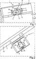
In
Das Gehäuse
Die Trägerarme
Die Befestigungsplatte
An der dem Fahrzeugbauteil
Zwischen dem Grundkörper
An dem Streifen
Das gesamte Gehäuse
Das gesamte Gehäuse
Von der Befestigungsplatte
In
Von der Befestigungsplatte
Außerdem sind die Rastnasen
In
Bei der Montage des Gehäuses
ZITATE ENTHALTEN IN DER BESCHREIBUNG QUOTES INCLUDE IN THE DESCRIPTION
Diese Liste der vom Anmelder aufgeführten Dokumente wurde automatisiert erzeugt und ist ausschließlich zur besseren Information des Lesers aufgenommen. Die Liste ist nicht Bestandteil der deutschen Patent- bzw. Gebrauchsmusteranmeldung. Das DPMA übernimmt keinerlei Haftung für etwaige Fehler oder Auslassungen.This list of the documents listed by the applicant has been generated automatically and is included solely for the better information of the reader. The list is not part of the German patent or utility model application. The DPMA assumes no liability for any errors or omissions.
Zitierte PatentliteraturCited patent literature
- DE 10334734 B4[0003, 0007, 0013]DE 10334734 B4[0003, 0007, 0013]
Claims (12)
Translated fromGermanPriority Applications (2)
| Application Number | Priority Date | Filing Date | Title |
|---|---|---|---|
| DE102011109829ADE102011109829A1 (en) | 2011-08-09 | 2011-08-09 | Fastening arrangement of a housing of a vehicle component to a vehicle component and housing for a vehicle component |
| EP12178632AEP2557318A1 (en) | 2011-08-09 | 2012-07-31 | Fixing arrangement of a casing of a vehicle component on a vehicle element and casing for a vehicle component |
Applications Claiming Priority (1)
| Application Number | Priority Date | Filing Date | Title |
|---|---|---|---|
| DE102011109829ADE102011109829A1 (en) | 2011-08-09 | 2011-08-09 | Fastening arrangement of a housing of a vehicle component to a vehicle component and housing for a vehicle component |
Publications (1)
| Publication Number | Publication Date |
|---|---|
| DE102011109829A1true DE102011109829A1 (en) | 2013-02-14 |
Family
ID=46682689
Family Applications (1)
| Application Number | Title | Priority Date | Filing Date |
|---|---|---|---|
| DE102011109829APendingDE102011109829A1 (en) | 2011-08-09 | 2011-08-09 | Fastening arrangement of a housing of a vehicle component to a vehicle component and housing for a vehicle component |
Country Status (2)
| Country | Link |
|---|---|
| EP (1) | EP2557318A1 (en) |
| DE (1) | DE102011109829A1 (en) |
Families Citing this family (1)
| Publication number | Priority date | Publication date | Assignee | Title |
|---|---|---|---|---|
| US7317409B2 (en) | 2002-01-30 | 2008-01-08 | Tensys Medical, Inc. | Apparatus and method for interfacing time-variant signals |
Citations (7)
| Publication number | Priority date | Publication date | Assignee | Title |
|---|---|---|---|---|
| US2390752A (en)* | 1944-01-31 | 1945-12-11 | Tinnerman Products Inc | Fastening device |
| EP0328759A1 (en)* | 1988-02-17 | 1989-08-23 | ALFRED TEVES GmbH | Device for fixing a brake booster |
| DE19541180A1 (en)* | 1995-11-04 | 1997-05-07 | Mst Automotive Gmbh | Means for fastening an airbag module |
| DE20319556U1 (en)* | 2003-12-17 | 2004-03-11 | A. Raymond & Cie | Bracket for mounting fittings at a spacing from a mounting surface has a movable inner cage with thrust support for end of securing screw |
| DE10334734B4 (en) | 2003-07-30 | 2006-03-23 | Adam Opel Ag | Fastening device with tolerance compensation |
| DE102006001741A1 (en)* | 2006-01-13 | 2007-08-02 | A. Raymond Et Cie | Captive threaded nut for latching into hole in plate is formed with self retaining spring arms |
| US20110020092A1 (en)* | 2009-07-24 | 2011-01-27 | Pem Management, Inc. | Quick acting panel fastener |
Family Cites Families (2)
| Publication number | Priority date | Publication date | Assignee | Title |
|---|---|---|---|---|
| GB2281586B (en)* | 1993-09-01 | 1996-10-02 | Sumitomo Wall Systems Ltd | A wiring harness clamp |
| DE102010004686A1 (en)* | 2010-01-15 | 2011-07-21 | Audi Ag, 85057 | Snap-fit connection unit for motor vehicle assembly, has snap-in hooks extending over dimension of threaded bolt in transverse extension, and straight-line arranged snap-in projection provided in area of free ends of snap-in hooks |
- 2011
- 2011-08-09DEDE102011109829Apatent/DE102011109829A1/enactivePending
- 2012
- 2012-07-31EPEP12178632Apatent/EP2557318A1/ennot_activeWithdrawn
Patent Citations (7)
| Publication number | Priority date | Publication date | Assignee | Title |
|---|---|---|---|---|
| US2390752A (en)* | 1944-01-31 | 1945-12-11 | Tinnerman Products Inc | Fastening device |
| EP0328759A1 (en)* | 1988-02-17 | 1989-08-23 | ALFRED TEVES GmbH | Device for fixing a brake booster |
| DE19541180A1 (en)* | 1995-11-04 | 1997-05-07 | Mst Automotive Gmbh | Means for fastening an airbag module |
| DE10334734B4 (en) | 2003-07-30 | 2006-03-23 | Adam Opel Ag | Fastening device with tolerance compensation |
| DE20319556U1 (en)* | 2003-12-17 | 2004-03-11 | A. Raymond & Cie | Bracket for mounting fittings at a spacing from a mounting surface has a movable inner cage with thrust support for end of securing screw |
| DE102006001741A1 (en)* | 2006-01-13 | 2007-08-02 | A. Raymond Et Cie | Captive threaded nut for latching into hole in plate is formed with self retaining spring arms |
| US20110020092A1 (en)* | 2009-07-24 | 2011-01-27 | Pem Management, Inc. | Quick acting panel fastener |
Also Published As
| Publication number | Publication date |
|---|---|
| EP2557318A1 (en) | 2013-02-13 |
Similar Documents
| Publication | Publication Date | Title |
|---|---|---|
| DE102013005801B4 (en) | Support device for attachment to a window of a motor vehicle and motor vehicles | |
| DE102013216555B4 (en) | Fastening device for a battery in a motor vehicle | |
| DE102010005485A1 (en) | support part | |
| DE102010015179A1 (en) | Arrangement for fastening vehicles parts at carcass body of vehicle, has two fastening parts, where one of fastening parts is provided opposite to another fastening part and moved in certain directions | |
| EP2698549A1 (en) | Component connection | |
| EP2019765A1 (en) | Device and method for fastening a wiper motor to a wiper linkage | |
| DE102012003617A1 (en) | Housing for control device of motor car, has attachment element connectable with component of motor car and engaged in recess of housing in form-fit manner such that housing is fastenable at component without retainer | |
| EP3763572B1 (en) | Device for holding a vehicle license plate | |
| EP2608990B1 (en) | Fastening of fastening part of an airbag module with a connecting part of a vehicle body structure | |
| DE102017221890A1 (en) | Sensor arrangement and motor vehicle | |
| DE102011109829A1 (en) | Fastening arrangement of a housing of a vehicle component to a vehicle component and housing for a vehicle component | |
| DE102007032929A1 (en) | Mounting device for fixing shock absorber covering, has fastening bar which is formed partially u-shaped, is inserted on border area such that border area is moved in u-shaped fastening bar in terminally mounted position | |
| DE102007009154A1 (en) | component holder | |
| DE102015219814A1 (en) | Car jack for a motor vehicle and method for assembling such a jack | |
| DE10210383B4 (en) | mounting spring | |
| DE102007019935A1 (en) | Fixing arrangement has bumper and fender with flange, where fender is locked in assembled condition of bumpers over support beam and bumper is connected with fender by additional connection | |
| DE102011116134B4 (en) | Vehicle module and vehicle with a vehicle module and method for assembling a vehicle module | |
| EP1612432B1 (en) | Fastening assembly for a trim panel and fastening method | |
| DE202014003576U1 (en) | Frameless license plate holder | |
| DE102021205869A1 (en) | Fastening device, roof antenna module and method | |
| DE102004024088B4 (en) | Spread clip for connecting two construction units, has spread pin inserted into insertion opening in area of spread units, and cam band inserted into area of recess of one construction unit based on slotted hole form | |
| DE102012018480B3 (en) | Mounting device for fixing seat belt in frame of vehicle seat, has spring unit arranged at holding unit, such that spring unit allows longitudinal displacement of bracket in mounting position, and locking element is arranged at spring unit | |
| DE102017000481A1 (en) | Anbauteilejustiervorrichtung and method for adjusting an attachment | |
| DE102010005309A1 (en) | Lining part i.e. interior lining part, for door of vehicle, has two brackets comprising two locking elements that are arranged one behind other in axial direction such that lining part is formed with tolerance in horizontal direction | |
| DE102007038737A1 (en) | Base plate for sensor assembly of controller in vehicle, has mounting plate with discharging elements for accommodating sensor module, and guide element co-operating with receiving element of carrier body |
Legal Events
| Date | Code | Title | Description |
|---|---|---|---|
| R163 | Identified publications notified | ||
| R012 | Request for examination validly filed | ||
| R016 | Response to examination communication |