DE102011109369A1 - Method and device for producing a three-dimensional object with fiber feed - Google Patents
Method and device for producing a three-dimensional object with fiber feedDownload PDFInfo
- Publication number
- DE102011109369A1 DE102011109369A1DE102011109369ADE102011109369ADE102011109369A1DE 102011109369 A1DE102011109369 A1DE 102011109369A1DE 102011109369 ADE102011109369 ADE 102011109369ADE 102011109369 ADE102011109369 ADE 102011109369ADE 102011109369 A1DE102011109369 A1DE 102011109369A1
- Authority
- DE
- Germany
- Prior art keywords
- solidifiable material
- fiber
- discharge unit
- fiber element
- dimensional object
- Prior art date
- Legal status (The legal status is an assumption and is not a legal conclusion. Google has not performed a legal analysis and makes no representation as to the accuracy of the status listed.)
- Withdrawn
Links
- 239000000835fiberSubstances0.000titleclaimsabstractdescription73
- 238000000034methodMethods0.000titleclaimsabstractdescription27
- 239000000463materialSubstances0.000claimsabstractdescription108
- 238000004519manufacturing processMethods0.000claimsabstractdescription18
- 239000012530fluidSubstances0.000claimsabstractdescription14
- 238000003860storageMethods0.000claimsdescription10
- 230000033001locomotionEffects0.000claimsdescription6
- 238000007599dischargingMethods0.000claimsdescription5
- 238000007711solidificationMethods0.000claimsdescription3
- 230000008023solidificationEffects0.000claimsdescription3
- 239000007788liquidSubstances0.000claimsdescription2
- 150000001875compoundsChemical class0.000claims1
- 230000029305taxisEffects0.000claims1
- 238000005496temperingMethods0.000claims1
- 238000001746injection mouldingMethods0.000description9
- 239000004033plasticSubstances0.000description7
- 230000015572biosynthetic processEffects0.000description4
- 238000010276constructionMethods0.000description4
- 239000004744fabricSubstances0.000description3
- 229920001296polysiloxanePolymers0.000description3
- 239000000843powderSubstances0.000description3
- 238000001125extrusionMethods0.000description2
- 239000000155meltSubstances0.000description2
- 230000008018meltingEffects0.000description2
- 238000002844meltingMethods0.000description2
- 230000002787reinforcementEffects0.000description2
- 239000011347resinSubstances0.000description2
- 229920005989resinPolymers0.000description2
- BUHVIAUBTBOHAG-FOYDDCNASA-N(2r,3r,4s,5r)-2-[6-[[2-(3,5-dimethoxyphenyl)-2-(2-methylphenyl)ethyl]amino]purin-9-yl]-5-(hydroxymethyl)oxolane-3,4-diolChemical compoundCOC1=CC(OC)=CC(C(CNC=2C=3N=CN(C=3N=CN=2)[C@H]2[C@@H]([C@H](O)[C@@H](CO)O2)O)C=2C(=CC=CC=2)C)=C1BUHVIAUBTBOHAG-FOYDDCNASA-N0.000description1
- 239000000853adhesiveSubstances0.000description1
- 230000001070adhesive effectEffects0.000description1
- 239000002131composite materialSubstances0.000description1
- 230000001276controlling effectEffects0.000description1
- 230000008878couplingEffects0.000description1
- 238000010168coupling processMethods0.000description1
- 238000005859coupling reactionMethods0.000description1
- 238000005516engineering processMethods0.000description1
- 238000005470impregnationMethods0.000description1
- 238000002347injectionMethods0.000description1
- 239000007924injectionSubstances0.000description1
- 230000010354integrationEffects0.000description1
- 239000011159matrix materialSubstances0.000description1
- 238000000465mouldingMethods0.000description1
- 238000007639printingMethods0.000description1
- 230000001105regulatory effectEffects0.000description1
- 230000003014reinforcing effectEffects0.000description1
- 230000008961swellingEffects0.000description1
- 229920001169thermoplasticPolymers0.000description1
- 239000012815thermoplastic materialSubstances0.000description1
- 239000004416thermosoftening plasticSubstances0.000description1
Images


Classifications
- B—PERFORMING OPERATIONS; TRANSPORTING
- B29—WORKING OF PLASTICS; WORKING OF SUBSTANCES IN A PLASTIC STATE IN GENERAL
- B29C—SHAPING OR JOINING OF PLASTICS; SHAPING OF MATERIAL IN A PLASTIC STATE, NOT OTHERWISE PROVIDED FOR; AFTER-TREATMENT OF THE SHAPED PRODUCTS, e.g. REPAIRING
- B29C70/00—Shaping composites, i.e. plastics material comprising reinforcements, fillers or preformed parts, e.g. inserts
- B29C70/04—Shaping composites, i.e. plastics material comprising reinforcements, fillers or preformed parts, e.g. inserts comprising reinforcements only, e.g. self-reinforcing plastics
- B29C70/06—Fibrous reinforcements only
- B29C70/10—Fibrous reinforcements only characterised by the structure of fibrous reinforcements, e.g. hollow fibres
- B29C70/16—Fibrous reinforcements only characterised by the structure of fibrous reinforcements, e.g. hollow fibres using fibres of substantial or continuous length
- B—PERFORMING OPERATIONS; TRANSPORTING
- B29—WORKING OF PLASTICS; WORKING OF SUBSTANCES IN A PLASTIC STATE IN GENERAL
- B29C—SHAPING OR JOINING OF PLASTICS; SHAPING OF MATERIAL IN A PLASTIC STATE, NOT OTHERWISE PROVIDED FOR; AFTER-TREATMENT OF THE SHAPED PRODUCTS, e.g. REPAIRING
- B29C64/00—Additive manufacturing, i.e. manufacturing of three-dimensional [3D] objects by additive deposition, additive agglomeration or additive layering, e.g. by 3D printing, stereolithography or selective laser sintering
- B29C64/10—Processes of additive manufacturing
- B29C64/106—Processes of additive manufacturing using only liquids or viscous materials, e.g. depositing a continuous bead of viscous material
- B29C64/112—Processes of additive manufacturing using only liquids or viscous materials, e.g. depositing a continuous bead of viscous material using individual droplets, e.g. from jetting heads
- B—PERFORMING OPERATIONS; TRANSPORTING
- B29—WORKING OF PLASTICS; WORKING OF SUBSTANCES IN A PLASTIC STATE IN GENERAL
- B29C—SHAPING OR JOINING OF PLASTICS; SHAPING OF MATERIAL IN A PLASTIC STATE, NOT OTHERWISE PROVIDED FOR; AFTER-TREATMENT OF THE SHAPED PRODUCTS, e.g. REPAIRING
- B29C64/00—Additive manufacturing, i.e. manufacturing of three-dimensional [3D] objects by additive deposition, additive agglomeration or additive layering, e.g. by 3D printing, stereolithography or selective laser sintering
- B29C64/10—Processes of additive manufacturing
- B29C64/106—Processes of additive manufacturing using only liquids or viscous materials, e.g. depositing a continuous bead of viscous material
- B29C64/118—Processes of additive manufacturing using only liquids or viscous materials, e.g. depositing a continuous bead of viscous material using filamentary material being melted, e.g. fused deposition modelling [FDM]
- B—PERFORMING OPERATIONS; TRANSPORTING
- B29—WORKING OF PLASTICS; WORKING OF SUBSTANCES IN A PLASTIC STATE IN GENERAL
- B29C—SHAPING OR JOINING OF PLASTICS; SHAPING OF MATERIAL IN A PLASTIC STATE, NOT OTHERWISE PROVIDED FOR; AFTER-TREATMENT OF THE SHAPED PRODUCTS, e.g. REPAIRING
- B29C45/00—Injection moulding, i.e. forcing the required volume of moulding material through a nozzle into a closed mould; Apparatus therefor
- B29C45/17—Component parts, details or accessories; Auxiliary operations
- B29C45/46—Means for plasticising or homogenising the moulding material or forcing it into the mould
- B29C45/461—Injection of measured doses
- B—PERFORMING OPERATIONS; TRANSPORTING
- B29—WORKING OF PLASTICS; WORKING OF SUBSTANCES IN A PLASTIC STATE IN GENERAL
- B29C—SHAPING OR JOINING OF PLASTICS; SHAPING OF MATERIAL IN A PLASTIC STATE, NOT OTHERWISE PROVIDED FOR; AFTER-TREATMENT OF THE SHAPED PRODUCTS, e.g. REPAIRING
- B29C70/00—Shaping composites, i.e. plastics material comprising reinforcements, fillers or preformed parts, e.g. inserts
- B29C70/04—Shaping composites, i.e. plastics material comprising reinforcements, fillers or preformed parts, e.g. inserts comprising reinforcements only, e.g. self-reinforcing plastics
- B29C70/28—Shaping operations therefor
- B29C70/30—Shaping by lay-up, i.e. applying fibres, tape or broadsheet on a mould, former or core; Shaping by spray-up, i.e. spraying of fibres on a mould, former or core
- B29C70/38—Automated lay-up, e.g. using robots, laying filaments according to predetermined patterns
- B29C70/382—Automated fiber placement [AFP]
- B—PERFORMING OPERATIONS; TRANSPORTING
- B29—WORKING OF PLASTICS; WORKING OF SUBSTANCES IN A PLASTIC STATE IN GENERAL
- B29K—INDEXING SCHEME ASSOCIATED WITH SUBCLASSES B29B, B29C OR B29D, RELATING TO MOULDING MATERIALS OR TO MATERIALS FOR MOULDS, REINFORCEMENTS, FILLERS OR PREFORMED PARTS, e.g. INSERTS
- B29K2105/00—Condition, form or state of moulded material or of the material to be shaped
- B29K2105/06—Condition, form or state of moulded material or of the material to be shaped containing reinforcements, fillers or inserts
- B29K2105/08—Condition, form or state of moulded material or of the material to be shaped containing reinforcements, fillers or inserts of continuous length, e.g. cords, rovings, mats, fabrics, strands or yarns
Landscapes
- Engineering & Computer Science (AREA)
- Chemical & Material Sciences (AREA)
- Materials Engineering (AREA)
- Mechanical Engineering (AREA)
- Physics & Mathematics (AREA)
- Manufacturing & Machinery (AREA)
- Optics & Photonics (AREA)
- Textile Engineering (AREA)
- Composite Materials (AREA)
Abstract
Translated fromGermanDescription
Translated fromGermanGebiet der ErfindungField of the invention
Die Erfindung betrifft ein Verfahren und eine Vorrichtung zur Herstellung eines dreidimensionalen Gegenstandes aus verfestigbarem Material, das entweder im Ausgangszustand als Fluid vorliegt oder verflüssigt werden kann, nach dem Oberbegriff der Ansprüche 1 und 13.The invention relates to a method and an apparatus for producing a three-dimensional article of solidifiable material, which is either present in the initial state as a fluid or can be liquefied, according to the preamble of
Stand der TechnikState of the art
In der Kunststoffteileherstellung ist bekannt, durch Spritzgießen oder Extrudieren in großen Losgrößen und Serien Teile unter Verwendung von Formwerkzeugen herzustellen. Der Vorteil des Kunststoff-Spritzgießens beruht insbesondere auf der hochgenauen Herstellung von komplexen Teilgeometrien, wobei die Funktionsvielfalt des Spritzgießverfahrens in optimaler Weise die Anforderungen an eine kostengünstige und wirtschaftliche Produktion von Kunststoffteilen abdeckt.In the production of plastic parts, it is known to produce parts using molding tools by injection molding or extrusion in large batch sizes and series. The advantage of plastic injection molding is based in particular on the high-precision production of complex part geometries, wherein the functional diversity of the injection molding process optimally covers the requirements for cost-effective and economical production of plastic parts.
Gleichzeitig wächst mehr und mehr ein Bedarf nach Kunststoffteilen für Stückzahl 1 und kleine Losgrößen, wie z. B. Musterteile mit der Anforderung einer sehr kurzzeitigen Bereitstellung sowie Eigenschaften, die denen von spritzgegossenen Teilen ähnlich sind. Zur Herstellung solcher Teile gibt es Fertigungsverfahren, die weitläufig unter dem Begriff Prototyping und Rapid Manufacturing bekannt sind. Die Herstellung solcher Teile beruht werkzeuglos, d. h. ohne Formwerkzeuge, in den meisten Fällen auf der Erzeugung der Geometrie aus 3D-Daten. Diese Geometrien werden in unterschiedlichster Form durch entsprechende Mittel wie Aufschmelzen von Pulverschichten durch Wärmeeintrag, z. B. mit Laser, generative Systeme wie Druckverfahren in unterschiedlicher verbindender Form der Pulverteile oder auch im sogenannten Schmelzstrangverfahren hergestellt.At the same time, there is a growing demand for plastic parts for 1 and small lot sizes such. For example, sample parts requiring a very short term delivery and properties similar to those of injection molded parts. For the production of such parts, there are manufacturing methods that are widely known by the term prototyping and rapid manufacturing. The production of such parts is tool-free, d. H. without forming tools, in most cases on the generation of geometry from 3D data. These geometries are in various forms by appropriate means such as melting of powder layers by heat input, z. B. with laser, generative systems such as printing processes in different connecting form of the powder parts or in the so-called melt extrusion process.
Aus der dem Oberbegriff des Anspruches 1 zugrunde liegenden
Aus der
Offenbarung der ErfindungDisclosure of the invention
Ausgehend von diesem Stand der Technik liegt der vorliegenden Erfindung die Aufgabe zugrunde, ein Verfahren und eine Vorrichtung zur Herstellung eines dreidimensionalen Gegenstandes im generativen Verfahren mit verbesserten Werkstoffeigenschaften zur Verfügung zu stellen.Based on this prior art, the present invention has the object to provide a method and apparatus for producing a three-dimensional object in the generative process with improved material properties available.
Diese Aufgabe wird durch ein Verfahren mit den Merkmalen des Anspruches 1 sowie durch eine Vorrichtung mit den Merkmalen des Anspruches 13 gelöst.This object is achieved by a method having the features of claim 1 and by an apparatus having the features of
In der Praxis hat sich herausgestellt, dass bei Herstellung von räumlichen Teilen wie Rapid-Prototyping-Teilen aus verfestigbarem Material, wie zum Beispiel üblichem thermoplastischem Material, regelmäßig auch Werkstückeigenschaften erwünscht sind, die durch die Materialen an sich nicht ohne weiteres gewährleistet werden können. Faserverstärkte Materialien können hier zwar Abhilfe leisten, insbesondere bei Ausbringen von Tropfen wäre jedoch der Faseranteil und seine verstärkende Wirkung zu gering.In practice, it has been found that in the production of spatial parts such as rapid prototyping parts of solidifiable material, such as conventional thermoplastic material, regularly workpiece properties are desired, which can not be ensured by the materials in itself easily. Although fiber-reinforced materials can remedy this situation, the proportion of fibers and their reinforcing effect would be too low, especially when drops are applied.
Aus diesem Grund wird ein endloses Faserelement dem verfestigbaren Material gleichzeitig mit dem Austragen des Materials aus der Austragseinheit zugeführt, so dass das Faserelement beim Austragen des Materials in dieses eingebettet werden kann und einen Verbund damit eingehen kann. Beliebige Formen des Gegenstands können gebildet werden, wozu vorzugsweise die Bewegung von Bauteil und gegebenenfalls auch der Austragseinheit sowie der Faserzuführeinrichtung jeweils gesondert relativ zueinander im Raum während des generativen, formerzeugenden Aufbaus des Gegenstandes erfolgen kann.For this reason, an endless fiber element is supplied to the solidifiable material simultaneously with the discharge of the material from the discharge unit, so that the fiber element can be embedded in the discharge of the material in this and can form a composite with it. Any shapes of the article may be formed, for which purpose preferably the movement of the component and possibly also of the dispensing unit and the fiber feed device may each take place separately relative to each other in space during the generative, shape-generating structure of the article.
Durch die Faserverstärkung kann bedarfsweise eine Stützstruktur dadurch erzeugt werden, dass z. B. für die erste Baureihe ein Faserelement gespannt wird oder indem Faserelemente dafür sorgen, dass Überhänge am Gegenstand angeformt werden können. Damit kann auf zusätzliche Abstützungen verzichtet werden.If necessary, a support structure can be generated by the fiber reinforcement, that z. B. for the first series a fiber element is stretched or by fiber elements ensure that overhangs are formed on the object can. This can be dispensed with additional supports.
Das verfestigbare Material kann tropfenweise, strangweise oder auch zur schnelleren Bauteilbildung abschnittsweise tropfen- und strangweise ausgetragen werden.The solidifiable material can be dropwise, strandwise or in sections for faster component formation dropwise and stranded discharged.
Werden alternativ mehrere Austragseinheiten vorgesehen, lassen sich zum Beispiel auch ablösbare Abstützungen erstellen oder im Außenbereich, in dem die Konturen des Gegenstands gebildet werden, können andere Materialien eingesetzt werden als im Inneren, wo zum Beispiel faserverstärkte Harz-/Silikonstrukturen verwendet werden, die in einer Aushärtestation schichtweise vernetzt werden können.If, alternatively, a plurality of dispensing units are provided, it is also possible, for example, to provide detachable supports, or in the outside area in which the contours of the object are formed, materials other than those inside can be used, for example fiber-reinforced resin / silicone structures which are used in one Curing station can be crosslinked in layers.
Die Faserzuführeinrichtung kann der Austragseinheit zugeordnet oder auch in diese integriert sein. Vorzugsweise ist sie jedoch getrennt von der Austragseinheit vorgesehen, da dadurch die Faserstrukturen besser beeinflusst werden können. So ist es zum Beispiel möglich, eine Gewebestruktur zu erzeugen, indem zum Beispiel von Schicht zu Schicht die Faser anders orientiert eingebettet wird.The fiber supply device can be assigned to the discharge unit or integrated into it. Preferably, however, it is provided separately from the discharge unit, as this can better influence the fiber structures. For example, it is possible to create a fabric structure by, for example, embedding the fiber differently oriented from layer to layer.
Weitere Vorteile ergeben sich aus den Unteransprüchen und der nachfolgenden Beschreibung.Further advantages emerge from the subclaims and the following description.
Kurzbeschreibung der FigurenBrief description of the figures
Im Folgenden wird die Erfindung anhand von den in den Figuren dargestellten Ausführungsbeispielen näher erläutert. Es zeigen:In the following, the invention will be explained in more detail with reference to the exemplary embodiments illustrated in the figures. Show it:
Beschreibung bevorzugter AusführungsbeispieleDescription of preferred embodiments
Bevor die Erfindung im Detail beschrieben wird, ist darauf hinzuweisen, dass sie nicht auf die jeweiligen Bauteile der Vorrichtung sowie die jeweiligen Verfahrensschritte beschränkt ist, da diese Bauteile und Verfahren variieren können. Die hier verwendeten Begriffe sind lediglich dafür bestimmt, besondere Ausführungsformen zu beschreiben und werden nicht einschränkend verwendet. Wenn zudem in der Beschreibung oder in den Ansprüchen die Einzahl oder unbestimmte Artikel verwendet werden, bezieht sich dies auch auf die Mehrzahl dieser Elemente, solange nicht der Gesamtzusammenhang eindeutig etwas Anderes deutlich macht.Before describing the invention in detail, it should be noted that it is not limited to the respective components of the device and the respective method steps, since these components and methods may vary. The terms used herein are intended only to describe particular embodiments and are not intended to be limiting. In addition, if singular or indefinite articles are used in the specification or claims, this also applies to the majority of these elements unless the overall context clearly makes otherwise clear.
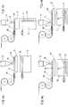
Die Figuren zeigen eine Vorrichtung zur Herstellung eines dreidimensionalen Gegenstandes
Durch das Austragen des verfestigbaren Materials erfolgt ein generativer Aufbau des Gegenstands
Da es für die Verwendung der Vorrichtung und auch für das Verfahren wesentlich ist, wird hier auch auf die Eigenschaft des Materials eingegangen. Das verfestigbare Material ist ein plastifiziertes Material wie zum Beispiel Silikon oder ein plastifizierbares Material wie Kunststoff oder auch pulverförmige Materialien, wobei es im Wesentlichen darauf ankommt, dass das verfestigbare Material entweder im Ausgangszustand in einer fluiden Phase vorliegt oder verflüssigt werden kann. Das Material kann auch ein unter Wärme reversibel aufschmelzbares und damit recycelbares Material sein. Beliebige andere Materialien können verwendet werden, sofern diese Materialien durch die Vorrichtung plastifizierbar und vor allem durch die wenigstens enie Austragseinheit
Das verfestigbare Material weist in der fluiden Phase einen sogenannten laminaren Quellfluss auf. In den Quellfluss geht u. a. die Anlagerung der Schmelze an der Wandung ein. Dies wird am deutlichsten bei einem Blick in die Erkenntnisse der Spritzgießtechnik. Bei der Formfüllung eines einfachen, rechteckigen Kanals wird die Schmelze über einen sogenannten Angusspunkt eingespritzt und beginnt sich von diesem Punkt mit geschlossenen Fließfronten kreisförmig auszubreiten, bis sie die gesamte Breite der Kavität ausfüllt. Einige Zeit danach kann der Bereich zwischen dem Einlauf und der Fließfront als nahezu ausgebildet betrachtet werden. An der Fließfront selbst herrscht eine besondere Strömungssituation, der ”Quellfluss”, da die Stromlinien in diesem Bereich wie eine Quelle erscheinen, wenn man sie in Bezug auf ein mitbewegtes Koordinatensystem betrachtet.The solidifiable material has a so-called laminar swelling flow in the fluid phase. In the source river u. a. the addition of the melt on the wall. This is most evident when looking at the ins and outs of injection molding technology. In the mold filling of a simple, rectangular channel, the melt is injected through a so-called gate point and begins to spread from this point with closed flow fronts in a circle until it fills the entire width of the cavity. Some time thereafter, the area between the inlet and the flow front can be considered to be nearly formed. On the river front itself, there is a special flow situation, the "source flow", as the streamlines in this area appear as a source when viewed in relation to a moving coordinate system.
Der laminare Quellfluss ist für die Erzeugung von wie hier auf einen Bauraum ,ausgerichteten' Tropfen
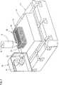
Die Vorrichtung weist gemäß
Die Austragseinheit
Das endlose Faserelement wird von der Faserzuführeinrichtung
Gemäß
Verfahrensgemäß wird das Material aufbereitet und dann in einem Materialspeicher
Das endlose Faserelement
Insbesondere bei Verwendung mehrerer Austragseinheiten
Die
In
Wird nun in der darüber liegenden Schicht der Objektträger gegenüber der Darstellung in den
In
BezugszeichenlisteLIST OF REFERENCE NUMBERS
- 12, 12'12, 12 '
- Austragseinheitdischarge unit
- 12a12a
- Austrittsöffnungoutlet opening
- 1313
- Objektträgerslides
- 18, 18'18, 18 '
- Materialspeichermaterial storage
- 5050
- Gegenstandobject
- 60, 60'60, 60 '
- Faserzuführeinrichtungfiber supply
- 61, 61''61, 61 ''
- Faserelementfiber element
- 61'61 '
- Faser eingebettetEmbedded fiber
- 62, 62'62, 62 '
- FaserkontrolleinrichtungFiber control device
- 7070
- Tropfendrops
- 8080
- Steuermittelcontrol means
- 9090
- PunktenergiequellePoint Energy
- 113113
- x-y-z Bautischx-y-z construction table
- 113'113 '
- 3D-Aktor3D actuator
ZITATE ENTHALTEN IN DER BESCHREIBUNG QUOTES INCLUDE IN THE DESCRIPTION
Diese Liste der vom Anmelder aufgeführten Dokumente wurde automatisiert erzeugt und ist ausschließlich zur besseren Information des Lesers aufgenommen. Die Liste ist nicht Bestandteil der deutschen Patent- bzw. Gebrauchsmusteranmeldung. Das DPMA übernimmt keinerlei Haftung für etwaige Fehler oder Auslassungen.This list of the documents listed by the applicant has been generated automatically and is included solely for the better information of the reader. The list is not part of the German patent or utility model application. The DPMA assumes no liability for any errors or omissions.
Zitierte PatentliteraturCited patent literature
- EP 1886793 A1[0004, 0025]EP 1886793 A1[0004, 0025]
- WO 2011/057712 A1[0005]WO 2011/057712 A1[0005]
Claims (17)
Translated fromGermanPriority Applications (3)
| Application Number | Priority Date | Filing Date | Title |
|---|---|---|---|
| DE102011109369ADE102011109369A1 (en) | 2011-08-04 | 2011-08-04 | Method and device for producing a three-dimensional object with fiber feed |
| PCT/EP2012/003316WO2013017284A2 (en) | 2011-08-04 | 2012-08-03 | Method and device for producing a three-dimensional object comprising a fiber feed |
| EP12753662.1AEP2739460B1 (en) | 2011-08-04 | 2012-08-03 | Method and device for producing a three-dimensional object comprising a fiber feed |
Applications Claiming Priority (1)
| Application Number | Priority Date | Filing Date | Title |
|---|---|---|---|
| DE102011109369ADE102011109369A1 (en) | 2011-08-04 | 2011-08-04 | Method and device for producing a three-dimensional object with fiber feed |
Publications (1)
| Publication Number | Publication Date |
|---|---|
| DE102011109369A1true DE102011109369A1 (en) | 2013-02-07 |
Family
ID=46785359
Family Applications (1)
| Application Number | Title | Priority Date | Filing Date |
|---|---|---|---|
| DE102011109369AWithdrawnDE102011109369A1 (en) | 2011-08-04 | 2011-08-04 | Method and device for producing a three-dimensional object with fiber feed |
Country Status (3)
| Country | Link |
|---|---|
| EP (1) | EP2739460B1 (en) |
| DE (1) | DE102011109369A1 (en) |
| WO (1) | WO2013017284A2 (en) |
Cited By (16)
| Publication number | Priority date | Publication date | Assignee | Title |
|---|---|---|---|---|
| DE102013003167A1 (en)* | 2013-02-26 | 2014-08-28 | Arburg Gmbh + Co. Kg | Method for producing a three-dimensional object by generative construction |
| EP2781342A1 (en)* | 2013-03-19 | 2014-09-24 | Eads UK Limited | Extrusion-based additive manufacturing |
| WO2015026847A1 (en)* | 2013-08-19 | 2015-02-26 | Aio Robotics, Inc. | Four-in-one three-dimensional copy machine |
| WO2015028809A1 (en)* | 2013-08-29 | 2015-03-05 | The University Of Warwick | Improvements relating to fused deposition modelling |
| EP2875935A1 (en)* | 2013-11-25 | 2015-05-27 | Przemyslowy Instytut Automatyki i Pomiarow PIAP | Device for 3D printing |
| WO2015188017A1 (en)* | 2014-06-04 | 2015-12-10 | Johnson Controls Interiors Management Gmbh | Fibre reinforced added manufacturing method and apparatus and fibre reinforced article obtained thereby |
| EP2960046A1 (en)* | 2014-06-23 | 2015-12-30 | Goodrich Corporation | Preforms for use in manufacturing composite structures and methods of making such preforms |
| CN106163772A (en)* | 2013-11-15 | 2016-11-23 | R·J·弗莱明 | Shape forming processes and their application to creating structural elements and designing objects |
| DE102015220699A1 (en)* | 2015-08-28 | 2017-03-02 | Siemens Aktiengesellschaft | Printed component and apparatus for 3-D printing in the gelling layer method |
| DE102015015615A1 (en)* | 2015-12-03 | 2017-06-08 | Audi Ag | Method for producing a component |
| DE102015122647A1 (en) | 2015-12-22 | 2017-06-22 | Arburg Gmbh + Co. Kg | Device and method for producing a three-dimensional object with a fiber feed device |
| DE102016214187A1 (en)* | 2016-08-01 | 2018-02-01 | Fraunhofer-Gesellschaft zur Förderung der angewandten Forschung e.V. | Method for producing a three-dimensional, multi-layered fiber composite component |
| US10479850B2 (en) | 2013-11-15 | 2019-11-19 | Robert J. Fleming | Shape forming process and application thereof for creating structural elements and designed objects |
| US10562226B1 (en) | 2013-03-15 | 2020-02-18 | Southern Methodist University | Additive manufacturing of active devices using dielectric, conductive, and magnetic materials |
| DE102021127700A1 (en) | 2021-10-25 | 2023-04-27 | Arburg Gmbh + Co Kg | Additive manufacturing process for producing a three-dimensional object and object produced therewith |
| EP3307508B1 (en)* | 2015-06-11 | 2025-04-23 | 9T Labs AG | Method for reinforcing a base structure |
Families Citing this family (64)
| Publication number | Priority date | Publication date | Assignee | Title |
|---|---|---|---|---|
| US9511543B2 (en) | 2012-08-29 | 2016-12-06 | Cc3D Llc | Method and apparatus for continuous composite three-dimensional printing |
| US11237542B2 (en) | 2013-03-22 | 2022-02-01 | Markforged, Inc. | Composite filament 3D printing using complementary reinforcement formations |
| US9815268B2 (en) | 2013-03-22 | 2017-11-14 | Markforged, Inc. | Multiaxis fiber reinforcement for 3D printing |
| US9186846B1 (en) | 2013-03-22 | 2015-11-17 | Markforged, Inc. | Methods for composite filament threading in three dimensional printing |
| US10682844B2 (en) | 2013-03-22 | 2020-06-16 | Markforged, Inc. | Embedding 3D printed fiber reinforcement in molded articles |
| US9126365B1 (en) | 2013-03-22 | 2015-09-08 | Markforged, Inc. | Methods for composite filament fabrication in three dimensional printing |
| US9956725B2 (en) | 2013-03-22 | 2018-05-01 | Markforged, Inc. | Three dimensional printer for fiber reinforced composite filament fabrication |
| US9694544B2 (en) | 2013-03-22 | 2017-07-04 | Markforged, Inc. | Methods for fiber reinforced additive manufacturing |
| US10259160B2 (en) | 2013-03-22 | 2019-04-16 | Markforged, Inc. | Wear resistance in 3D printing of composites |
| US9579851B2 (en) | 2013-03-22 | 2017-02-28 | Markforged, Inc. | Apparatus for fiber reinforced additive manufacturing |
| US9149988B2 (en) | 2013-03-22 | 2015-10-06 | Markforged, Inc. | Three dimensional printing |
| US9539762B2 (en) | 2013-03-22 | 2017-01-10 | Markforged, Inc. | 3D printing with kinematic coupling |
| US10953609B1 (en) | 2013-03-22 | 2021-03-23 | Markforged, Inc. | Scanning print bed and part height in 3D printing |
| US11981069B2 (en) | 2013-03-22 | 2024-05-14 | Markforged, Inc. | Three dimensional printing of composite reinforced structures |
| US9688028B2 (en) | 2013-03-22 | 2017-06-27 | Markforged, Inc. | Multilayer fiber reinforcement design for 3D printing |
| US9186848B2 (en) | 2013-03-22 | 2015-11-17 | Markforged, Inc. | Three dimensional printing of composite reinforced structures |
| US9156205B2 (en) | 2013-03-22 | 2015-10-13 | Markforged, Inc. | Three dimensional printer with composite filament fabrication |
| CN107187022B (en) | 2013-03-22 | 2020-08-11 | 格雷戈里·托马斯·马克 | Three-dimensional printing |
| US9126367B1 (en) | 2013-03-22 | 2015-09-08 | Markforged, Inc. | Three dimensional printer for fiber reinforced composite filament fabrication |
| EP3130444B1 (en) | 2013-06-05 | 2020-04-01 | Markforged, Inc. | Method for fiber reinforced additive manufacturing |
| US9808991B2 (en) | 2014-07-29 | 2017-11-07 | Cc3D Llc. | Method and apparatus for additive mechanical growth of tubular structures |
| US10232551B2 (en) | 2016-04-15 | 2019-03-19 | Cc3D Llc | Head and system for continuously manufacturing composite hollow structure |
| US10105910B2 (en) | 2016-04-15 | 2018-10-23 | Cc3D Llc | Method for continuously manufacturing composite hollow structure |
| US10759113B2 (en) | 2016-09-06 | 2020-09-01 | Continuous Composites Inc. | Additive manufacturing system having trailing cure mechanism |
| US10625467B2 (en) | 2016-09-06 | 2020-04-21 | Continuous Composites Inc. | Additive manufacturing system having adjustable curing |
| US10543640B2 (en) | 2016-09-06 | 2020-01-28 | Continuous Composites Inc. | Additive manufacturing system having in-head fiber teasing |
| US20180065307A1 (en) | 2016-09-06 | 2018-03-08 | Cc3D Llc | Systems and methods for controlling additive manufacturing |
| US20180065317A1 (en) | 2016-09-06 | 2018-03-08 | Cc3D Llc | Additive manufacturing system having in-situ fiber splicing |
| US10766594B2 (en) | 2016-11-03 | 2020-09-08 | Continuous Composites Inc. | Composite vehicle body |
| US20210094230A9 (en) | 2016-11-04 | 2021-04-01 | Continuous Composites Inc. | System for additive manufacturing |
| US10953598B2 (en) | 2016-11-04 | 2021-03-23 | Continuous Composites Inc. | Additive manufacturing system having vibrating nozzle |
| US10040240B1 (en) | 2017-01-24 | 2018-08-07 | Cc3D Llc | Additive manufacturing system having fiber-cutting mechanism |
| US10857726B2 (en) | 2017-01-24 | 2020-12-08 | Continuous Composites Inc. | Additive manufacturing system implementing anchor curing |
| US20180229092A1 (en) | 2017-02-13 | 2018-08-16 | Cc3D Llc | Composite sporting equipment |
| US10798783B2 (en) | 2017-02-15 | 2020-10-06 | Continuous Composites Inc. | Additively manufactured composite heater |
| US20190001563A1 (en) | 2017-06-29 | 2019-01-03 | Cc3D Llc | Print head for additive manufacturing system |
| US10814569B2 (en) | 2017-06-29 | 2020-10-27 | Continuous Composites Inc. | Method and material for additive manufacturing |
| US10319499B1 (en) | 2017-11-30 | 2019-06-11 | Cc3D Llc | System and method for additively manufacturing composite wiring harness |
| US10131088B1 (en) | 2017-12-19 | 2018-11-20 | Cc3D Llc | Additive manufacturing method for discharging interlocking continuous reinforcement |
| US10919222B2 (en) | 2017-12-29 | 2021-02-16 | Continuous Composites Inc. | System and method for additively manufacturing functional elements into existing components |
| US10081129B1 (en) | 2017-12-29 | 2018-09-25 | Cc3D Llc | Additive manufacturing system implementing hardener pre-impregnation |
| US10857729B2 (en) | 2017-12-29 | 2020-12-08 | Continuous Composites Inc. | System and method for additively manufacturing functional elements into existing components |
| US10759114B2 (en) | 2017-12-29 | 2020-09-01 | Continuous Composites Inc. | System and print head for continuously manufacturing composite structure |
| US11167495B2 (en) | 2017-12-29 | 2021-11-09 | Continuous Composites Inc. | System and method for additively manufacturing functional elements into existing components |
| US11161300B2 (en) | 2018-04-11 | 2021-11-02 | Continuous Composites Inc. | System and print head for additive manufacturing system |
| US11110656B2 (en) | 2018-04-12 | 2021-09-07 | Continuous Composites Inc. | System for continuously manufacturing composite structure |
| US11130284B2 (en) | 2018-04-12 | 2021-09-28 | Continuous Composites Inc. | System and head for continuously manufacturing composite structure |
| US11052603B2 (en) | 2018-06-07 | 2021-07-06 | Continuous Composites Inc. | Additive manufacturing system having stowable cutting mechanism |
| US20200086563A1 (en) | 2018-09-13 | 2020-03-19 | Cc3D Llc | System and head for continuously manufacturing composite structure |
| CN109049756B (en)* | 2018-09-30 | 2023-10-20 | 乐清市智能装备与制造研究院 | Continuous fiber composite shell manufacturing equipment |
| US11235522B2 (en) | 2018-10-04 | 2022-02-01 | Continuous Composites Inc. | System for additively manufacturing composite structures |
| US11511480B2 (en) | 2018-10-26 | 2022-11-29 | Continuous Composites Inc. | System for additive manufacturing |
| US11420390B2 (en) | 2018-11-19 | 2022-08-23 | Continuous Composites Inc. | System for additively manufacturing composite structure |
| US11358331B2 (en) | 2018-11-19 | 2022-06-14 | Continuous Composites Inc. | System and head for continuously manufacturing composite structure |
| US20200238603A1 (en) | 2019-01-25 | 2020-07-30 | Continuous Composites Inc. | System for additively manufacturing composite structure |
| US20200376758A1 (en) | 2019-05-28 | 2020-12-03 | Continuous Composites Inc. | System for additively manufacturing composite structure |
| US11840022B2 (en) | 2019-12-30 | 2023-12-12 | Continuous Composites Inc. | System and method for additive manufacturing |
| US11904534B2 (en) | 2020-02-25 | 2024-02-20 | Continuous Composites Inc. | Additive manufacturing system |
| US11926100B2 (en) | 2020-06-23 | 2024-03-12 | Continuous Composites Inc. | Systems and methods for controlling additive manufacturing |
| EP3957480A1 (en)* | 2020-08-21 | 2022-02-23 | Siemens Aktiengesellschaft | Assembly for material extrusion for the additive manufacturing of a three-dimensional object |
| US11613080B2 (en) | 2020-09-11 | 2023-03-28 | Continuous Composites Inc. | Print head for additive manufacturing system |
| US11926099B2 (en) | 2021-04-27 | 2024-03-12 | Continuous Composites Inc. | Additive manufacturing system |
| US12134226B2 (en) | 2021-10-20 | 2024-11-05 | Continuous Composites Inc. | Systems and methods of additive manufacturing |
| EP4495147A1 (en) | 2023-07-19 | 2025-01-22 | Lummus Novolen Technology GmbH | Propylene polymers for three-dimensional printing |
Citations (4)
| Publication number | Priority date | Publication date | Assignee | Title |
|---|---|---|---|---|
| US20020033548A1 (en)* | 1998-07-10 | 2002-03-21 | Dmitri Brodkin | Dental restorations formed by solid free-form fabrication methods |
| US20030236588A1 (en)* | 2002-03-14 | 2003-12-25 | Jang Bor Z. | Nanotube fiber reinforced composite materials and method of producing fiber reinforced composites |
| EP1886793A1 (en) | 2006-08-11 | 2008-02-13 | Karl Hehl | Method and device for manufacturing a 3D object and use of a plastifying unit for its manufacture |
| WO2011057712A1 (en) | 2009-11-13 | 2011-05-19 | Dr. Ing. H.C. F. Porsche Ag | Method for producing a component from a fibre-reinforced material |
Family Cites Families (6)
| Publication number | Priority date | Publication date | Assignee | Title |
|---|---|---|---|---|
| JPS6478822A (en)* | 1987-09-21 | 1989-03-24 | Yamanashi Pref Gov | Three-dimensional body molding equipment |
| DE4102257A1 (en)* | 1991-01-23 | 1992-07-30 | Artos Med Produkte | Appts. for mfg. reinforced components in laser-cured polymer - has laser-curable polymer in bath, laser directed at polymer surface where fibres pass through polymer and are guided relative to laser beam angle |
| US6175422B1 (en)* | 1991-01-31 | 2001-01-16 | Texas Instruments Incorporated | Method and apparatus for the computer-controlled manufacture of three-dimensional objects from computer data |
| CA2204792A1 (en)* | 1997-05-08 | 1998-11-08 | Tomasz Duczmal | Apparatus and method for constructing and sculpting shapes |
| US5936861A (en)* | 1997-08-15 | 1999-08-10 | Nanotek Instruments, Inc. | Apparatus and process for producing fiber reinforced composite objects |
| CN101462358B (en)* | 2007-12-19 | 2013-09-11 | 维斯塔斯风力系统有限公司 | An apparatus for preparing a pre-form |
- 2011
- 2011-08-04DEDE102011109369Apatent/DE102011109369A1/ennot_activeWithdrawn
- 2012
- 2012-08-03EPEP12753662.1Apatent/EP2739460B1/enactiveActive
- 2012-08-03WOPCT/EP2012/003316patent/WO2013017284A2/enunknown
Patent Citations (4)
| Publication number | Priority date | Publication date | Assignee | Title |
|---|---|---|---|---|
| US20020033548A1 (en)* | 1998-07-10 | 2002-03-21 | Dmitri Brodkin | Dental restorations formed by solid free-form fabrication methods |
| US20030236588A1 (en)* | 2002-03-14 | 2003-12-25 | Jang Bor Z. | Nanotube fiber reinforced composite materials and method of producing fiber reinforced composites |
| EP1886793A1 (en) | 2006-08-11 | 2008-02-13 | Karl Hehl | Method and device for manufacturing a 3D object and use of a plastifying unit for its manufacture |
| WO2011057712A1 (en) | 2009-11-13 | 2011-05-19 | Dr. Ing. H.C. F. Porsche Ag | Method for producing a component from a fibre-reinforced material |
Cited By (26)
| Publication number | Priority date | Publication date | Assignee | Title |
|---|---|---|---|---|
| DE102013003167A1 (en)* | 2013-02-26 | 2014-08-28 | Arburg Gmbh + Co. Kg | Method for producing a three-dimensional object by generative construction |
| US10040249B2 (en) | 2013-02-26 | 2018-08-07 | Arburg Gmbh + Co Kg | Method for producing a three-dimensional object by means of generative construction |
| US10857730B1 (en) | 2013-03-15 | 2020-12-08 | Southern Methodist University | Additive manufacturing of active devices using dielectric, conductive, and magnetic materials |
| US10562226B1 (en) | 2013-03-15 | 2020-02-18 | Southern Methodist University | Additive manufacturing of active devices using dielectric, conductive, and magnetic materials |
| US9908145B2 (en) | 2013-03-19 | 2018-03-06 | Airbus Group Limited | Extrusion-based additive manufacturing |
| EP2781342A1 (en)* | 2013-03-19 | 2014-09-24 | Eads UK Limited | Extrusion-based additive manufacturing |
| WO2015026847A1 (en)* | 2013-08-19 | 2015-02-26 | Aio Robotics, Inc. | Four-in-one three-dimensional copy machine |
| WO2015028809A1 (en)* | 2013-08-29 | 2015-03-05 | The University Of Warwick | Improvements relating to fused deposition modelling |
| CN106163772A (en)* | 2013-11-15 | 2016-11-23 | R·J·弗莱明 | Shape forming processes and their application to creating structural elements and designing objects |
| US10479850B2 (en) | 2013-11-15 | 2019-11-19 | Robert J. Fleming | Shape forming process and application thereof for creating structural elements and designed objects |
| EP3068608A4 (en)* | 2013-11-15 | 2017-08-09 | Robert J. Fleming | Shape forming process and application thereof for creating structural elements and designed objects |
| EP2875935A1 (en)* | 2013-11-25 | 2015-05-27 | Przemyslowy Instytut Automatyki i Pomiarow PIAP | Device for 3D printing |
| WO2015188017A1 (en)* | 2014-06-04 | 2015-12-10 | Johnson Controls Interiors Management Gmbh | Fibre reinforced added manufacturing method and apparatus and fibre reinforced article obtained thereby |
| US10532534B2 (en) | 2014-06-23 | 2020-01-14 | Goodrich Corporation | Preforms for use in manufacturing composite structures and methods of making such preforms |
| US10059075B2 (en) | 2014-06-23 | 2018-08-28 | Goodrich Corporation | Preforms for use in manufacturing composite structures and methods of making such preforms |
| EP2960046A1 (en)* | 2014-06-23 | 2015-12-30 | Goodrich Corporation | Preforms for use in manufacturing composite structures and methods of making such preforms |
| EP3307508B1 (en)* | 2015-06-11 | 2025-04-23 | 9T Labs AG | Method for reinforcing a base structure |
| DE102015220699A1 (en)* | 2015-08-28 | 2017-03-02 | Siemens Aktiengesellschaft | Printed component and apparatus for 3-D printing in the gelling layer method |
| DE102015015615A1 (en)* | 2015-12-03 | 2017-06-08 | Audi Ag | Method for producing a component |
| DE102015015615B4 (en)* | 2015-12-03 | 2020-02-27 | Audi Ag | Process and manufacturing system for manufacturing a component |
| CN108472884A (en)* | 2015-12-22 | 2018-08-31 | 阿博格有限公司 | Apparatus and method for manufacturing three-dimensional objects using fiber delivery devices |
| DE102015122647A1 (en) | 2015-12-22 | 2017-06-22 | Arburg Gmbh + Co. Kg | Device and method for producing a three-dimensional object with a fiber feed device |
| US11214003B2 (en) | 2015-12-22 | 2022-01-04 | Arburg Gmbh + Co Kg | Device and method for producing a three-dimensional object with a fibre feeding device |
| DE102016214187A1 (en)* | 2016-08-01 | 2018-02-01 | Fraunhofer-Gesellschaft zur Förderung der angewandten Forschung e.V. | Method for producing a three-dimensional, multi-layered fiber composite component |
| DE102021127700A1 (en) | 2021-10-25 | 2023-04-27 | Arburg Gmbh + Co Kg | Additive manufacturing process for producing a three-dimensional object and object produced therewith |
| DE102021127700B4 (en) | 2021-10-25 | 2024-12-05 | Arburg Gmbh + Co Kg | Additive manufacturing process for producing a three-dimensional object and object produced thereby |
Also Published As
| Publication number | Publication date |
|---|---|
| EP2739460A2 (en) | 2014-06-11 |
| EP2739460B1 (en) | 2016-05-18 |
| WO2013017284A2 (en) | 2013-02-07 |
| WO2013017284A3 (en) | 2013-10-03 |
Similar Documents
| Publication | Publication Date | Title |
|---|---|---|
| EP2739460B1 (en) | Method and device for producing a three-dimensional object comprising a fiber feed | |
| EP3393765B1 (en) | Device and method for producing a three-dimensional object with a fibre feeding device | |
| EP2961589B1 (en) | Method for producing a three-dimensional object by means of generative construction | |
| EP2720853B1 (en) | Device and method for the production of a three-dimensional object | |
| EP3313647B1 (en) | Method for the preparation of 3d objects | |
| EP1886793B1 (en) | Method and device for manufacturing a 3D object and use of a plastifying unit for its manufacture | |
| EP2739456B1 (en) | Method for producing a three-dimensional object from solidifiable material and the object produced thereby | |
| EP2611596B1 (en) | Method and apparatus for producing a three-dimensional object | |
| EP3204207B1 (en) | Method for the further processing of a prefabricated product, and associated prefabricated product | |
| DE112015002058T5 (en) | Apparatus and method for forming three-dimensional objects | |
| EP2328734A1 (en) | Method and apparatus for producing plastic products with integrated reinforcing structure | |
| EP2176059A1 (en) | Method and device for producing a reinforced composite product | |
| WO2015011289A1 (en) | Method for producing plastic components, which have a high mechanical load-bearing capacity, with a correct final contour | |
| DE102011106615A1 (en) | Device for producing a three-dimensional object | |
| EP2163368A1 (en) | Method and device for producing plastic products with partially provided structures | |
| EP2860020B1 (en) | Method of producing a three-dimensional object and corresponding object | |
| DE102014104680A1 (en) | Method and device for molding a component | |
| DE102014011135A1 (en) | Method and device for producing a decorative part | |
| EP2860021A1 (en) | Three-dimensional object including at least one wall surrounding an interior | |
| DE102016222658A1 (en) | Apparatus and method for producing a fiber-reinforced component of a fiber-reinforced core and at least one additive applied to the fiber-reinforced core plastic portion, and fiber-reinforced component | |
| DE102021107281A1 (en) | 3D PRINTING DEVICE AND 3D PRINTING PROCESS | |
| EP0340395A2 (en) | Method and apparatus for producing a composite plastics structure |
Legal Events
| Date | Code | Title | Description |
|---|---|---|---|
| R012 | Request for examination validly filed | ||
| R079 | Amendment of ipc main class | Free format text:PREVIOUS MAIN CLASS: B29C0067000000 Ipc:B29C0064106000 | |
| R120 | Application withdrawn or ip right abandoned |