DE102011102062A1 - Boom for universal farm loader that is utilized in e.g. gardens to drive cargo, has tool carrier arranged at vertically pivotable lifting arm, and swingable intermediate arm steered between horizontally pivotable swing gear and lift arm - Google Patents
Boom for universal farm loader that is utilized in e.g. gardens to drive cargo, has tool carrier arranged at vertically pivotable lifting arm, and swingable intermediate arm steered between horizontally pivotable swing gear and lift armDownload PDFInfo
- Publication number
- DE102011102062A1 DE102011102062A1DE201110102062DE102011102062ADE102011102062A1DE 102011102062 A1DE102011102062 A1DE 102011102062A1DE 201110102062DE201110102062DE 201110102062DE 102011102062 ADE102011102062 ADE 102011102062ADE 102011102062 A1DE102011102062 A1DE 102011102062A1
- Authority
- DE
- Germany
- Prior art keywords
- arm
- loading
- boom
- lifting
- tool carrier
- Prior art date
- Legal status (The legal status is an assumption and is not a legal conclusion. Google has not performed a legal analysis and makes no representation as to the accuracy of the status listed.)
- Withdrawn
Links
- 230000004888barrier functionEffects0.000claimsdescription2
- 239000004575stoneSubstances0.000description2
- BUHVIAUBTBOHAG-FOYDDCNASA-N(2r,3r,4s,5r)-2-[6-[[2-(3,5-dimethoxyphenyl)-2-(2-methylphenyl)ethyl]amino]purin-9-yl]-5-(hydroxymethyl)oxolane-3,4-diolChemical compoundCOC1=CC(OC)=CC(C(CNC=2C=3N=CN(C=3N=CN=2)[C@H]2[C@@H]([C@H](O)[C@@H](CO)O2)O)C=2C(=CC=CC=2)C)=C1BUHVIAUBTBOHAG-FOYDDCNASA-N0.000description1
- 238000009412basement excavationMethods0.000description1
- 238000010276constructionMethods0.000description1
- 230000001419dependent effectEffects0.000description1
- 238000009313farmingMethods0.000description1
- 230000006641stabilisationEffects0.000description1
- 238000011105stabilizationMethods0.000description1
Images


Classifications
- E—FIXED CONSTRUCTIONS
- E02—HYDRAULIC ENGINEERING; FOUNDATIONS; SOIL SHIFTING
- E02F—DREDGING; SOIL-SHIFTING
- E02F3/00—Dredgers; Soil-shifting machines
- E02F3/04—Dredgers; Soil-shifting machines mechanically-driven
- E02F3/28—Dredgers; Soil-shifting machines mechanically-driven with digging tools mounted on a dipper- or bucket-arm, i.e. there is either one arm or a pair of arms, e.g. dippers, buckets
- E02F3/34—Dredgers; Soil-shifting machines mechanically-driven with digging tools mounted on a dipper- or bucket-arm, i.e. there is either one arm or a pair of arms, e.g. dippers, buckets with bucket-arms, i.e. a pair of arms, e.g. manufacturing processes, form, geometry, material of bucket-arms directly pivoted on the frames of tractors or self-propelled machines
- E02F3/358—Bucket-arms pivoted on a turntable being part of a tractor frame or buckets arranged on a turntable supported by the arms
- B—PERFORMING OPERATIONS; TRANSPORTING
- B66—HOISTING; LIFTING; HAULING
- B66F—HOISTING, LIFTING, HAULING OR PUSHING, NOT OTHERWISE PROVIDED FOR, e.g. DEVICES WHICH APPLY A LIFTING OR PUSHING FORCE DIRECTLY TO THE SURFACE OF A LOAD
- B66F9/00—Devices for lifting or lowering bulky or heavy goods for loading or unloading purposes
- B66F9/06—Devices for lifting or lowering bulky or heavy goods for loading or unloading purposes movable, with their loads, on wheels or the like, e.g. fork-lift trucks
- B66F9/065—Devices for lifting or lowering bulky or heavy goods for loading or unloading purposes movable, with their loads, on wheels or the like, e.g. fork-lift trucks non-masted
- E—FIXED CONSTRUCTIONS
- E02—HYDRAULIC ENGINEERING; FOUNDATIONS; SOIL SHIFTING
- E02F—DREDGING; SOIL-SHIFTING
- E02F3/00—Dredgers; Soil-shifting machines
- E02F3/04—Dredgers; Soil-shifting machines mechanically-driven
- E02F3/28—Dredgers; Soil-shifting machines mechanically-driven with digging tools mounted on a dipper- or bucket-arm, i.e. there is either one arm or a pair of arms, e.g. dippers, buckets
- E02F3/30—Dredgers; Soil-shifting machines mechanically-driven with digging tools mounted on a dipper- or bucket-arm, i.e. there is either one arm or a pair of arms, e.g. dippers, buckets with a dipper-arm pivoted on a cantilever beam, i.e. boom
- E02F3/301—Dredgers; Soil-shifting machines mechanically-driven with digging tools mounted on a dipper- or bucket-arm, i.e. there is either one arm or a pair of arms, e.g. dippers, buckets with a dipper-arm pivoted on a cantilever beam, i.e. boom with more than two arms (boom included), e.g. two-part boom with additional dipper-arm
- E—FIXED CONSTRUCTIONS
- E02—HYDRAULIC ENGINEERING; FOUNDATIONS; SOIL SHIFTING
- E02F—DREDGING; SOIL-SHIFTING
- E02F3/00—Dredgers; Soil-shifting machines
- E02F3/04—Dredgers; Soil-shifting machines mechanically-driven
- E02F3/28—Dredgers; Soil-shifting machines mechanically-driven with digging tools mounted on a dipper- or bucket-arm, i.e. there is either one arm or a pair of arms, e.g. dippers, buckets
- E02F3/30—Dredgers; Soil-shifting machines mechanically-driven with digging tools mounted on a dipper- or bucket-arm, i.e. there is either one arm or a pair of arms, e.g. dippers, buckets with a dipper-arm pivoted on a cantilever beam, i.e. boom
- E02F3/306—Dredgers; Soil-shifting machines mechanically-driven with digging tools mounted on a dipper- or bucket-arm, i.e. there is either one arm or a pair of arms, e.g. dippers, buckets with a dipper-arm pivoted on a cantilever beam, i.e. boom with telescopic dipper-arm or boom
- E—FIXED CONSTRUCTIONS
- E02—HYDRAULIC ENGINEERING; FOUNDATIONS; SOIL SHIFTING
- E02F—DREDGING; SOIL-SHIFTING
- E02F3/00—Dredgers; Soil-shifting machines
- E02F3/04—Dredgers; Soil-shifting machines mechanically-driven
- E02F3/28—Dredgers; Soil-shifting machines mechanically-driven with digging tools mounted on a dipper- or bucket-arm, i.e. there is either one arm or a pair of arms, e.g. dippers, buckets
- E02F3/30—Dredgers; Soil-shifting machines mechanically-driven with digging tools mounted on a dipper- or bucket-arm, i.e. there is either one arm or a pair of arms, e.g. dippers, buckets with a dipper-arm pivoted on a cantilever beam, i.e. boom
- E02F3/308—Dredgers; Soil-shifting machines mechanically-driven with digging tools mounted on a dipper- or bucket-arm, i.e. there is either one arm or a pair of arms, e.g. dippers, buckets with a dipper-arm pivoted on a cantilever beam, i.e. boom working outwardly
- E—FIXED CONSTRUCTIONS
- E02—HYDRAULIC ENGINEERING; FOUNDATIONS; SOIL SHIFTING
- E02F—DREDGING; SOIL-SHIFTING
- E02F3/00—Dredgers; Soil-shifting machines
- E02F3/04—Dredgers; Soil-shifting machines mechanically-driven
- E02F3/28—Dredgers; Soil-shifting machines mechanically-driven with digging tools mounted on a dipper- or bucket-arm, i.e. there is either one arm or a pair of arms, e.g. dippers, buckets
- E02F3/34—Dredgers; Soil-shifting machines mechanically-driven with digging tools mounted on a dipper- or bucket-arm, i.e. there is either one arm or a pair of arms, e.g. dippers, buckets with bucket-arms, i.e. a pair of arms, e.g. manufacturing processes, form, geometry, material of bucket-arms directly pivoted on the frames of tractors or self-propelled machines
- E02F3/3405—Dredgers; Soil-shifting machines mechanically-driven with digging tools mounted on a dipper- or bucket-arm, i.e. there is either one arm or a pair of arms, e.g. dippers, buckets with bucket-arms, i.e. a pair of arms, e.g. manufacturing processes, form, geometry, material of bucket-arms directly pivoted on the frames of tractors or self-propelled machines and comprising an additional linkage mechanism
Landscapes
- Engineering & Computer Science (AREA)
- Structural Engineering (AREA)
- Civil Engineering (AREA)
- Mechanical Engineering (AREA)
- Mining & Mineral Resources (AREA)
- General Engineering & Computer Science (AREA)
- Transportation (AREA)
- Life Sciences & Earth Sciences (AREA)
- Geology (AREA)
- Shovels (AREA)
Abstract
Description
Translated fromGermanRadlader sind bekannte Ladegeräte, welche u. a. zum Laden und Transportieren von Gütern über kurze Strecken, beispielsweise eingesetzt als Baumaschinen, verwendet werden. Diese besitzen zumindest einen Werkzeugträger, an welchem unterschiedliche Werkzeuge, wie Schaufeln für Schüttgüter, Paletten-/Ladegabeln für palettierte Güter, Steingabeln zum Aufnehmen von Steinen oder ein Schneeschild, in üblicher Art befestigt werden können.Wheel loaders are known chargers, which u. a. used for loading and transporting goods over short distances, for example used as construction machines. These have at least one tool carrier on which different tools, such as shovels for bulk goods, pallets / forks for palletized goods, stone for picking up stones or a snow blade, can be attached in a conventional manner.
Ist am Werkzeugträger, der selbst an der Frontseite des Ladegerätes angeordnet ist, beispielsweise eine Schaufel angebracht, ist dieser Radlader für Erdbewegungsarbeiten geeignet. Das Werkzeug ist regelmäßig vertikal über einen Hubrahmen schwenkbar, wobei ein Schwenken aus der Horizontalen nach unten nicht ermöglicht ist. Der Werkzeugträger ist dabei regelmäßig in der Horizontalen nicht schwenkbar.If, for example, a blade is attached to the tool carrier, which itself is arranged on the front side of the charger, this wheel loader is suitable for earthmoving work. The tool is regularly vertically pivotable about a lifting frame, with a pivoting from the horizontal down is not possible. The tool carrier is regularly not pivotable in the horizontal.
Es sind außerdem Schwenklader bekannt, welche auch zu den Radladern gezählt werden. Im Unterschied zu konventionellen Radladern ist der Schaufelarm des Schwenkladers an einem in der Horizontalen verdrehbaren Schwenkwerk befestigt und lässt sich somit regelmäßig um bis zu 180° (2 × 90°) in der Horizontalen verschwenken.There are also known Schwenklader, which are also counted among the wheel loaders. In contrast to conventional wheel loaders, the blade arm of the pivoting peg is fastened to a swivel mechanism which can be rotated in the horizontal direction and can thus be pivoted regularly by up to 180 ° (2 × 90 °) in the horizontal.
Aus der
Ein weiteres bekanntes Ladegerät bzw. Lade- und Baggergerät ist der Baggerlader (auch Heckbagger genannt), der an seiner Frontseite eine Ladeschaufel und an der Heckseite einen Bagger besitzt.Another well-known charger or loading and digging device is the backhoe loader (also called backhoe), which has on its front side a loading shovel and on the rear side of an excavator.
Dieses Mehrzweckgerät umfasst mit seiner an der Front befindlichen Ladeschaufel die Funktionalität des Radladers und mit dem am Heck befindlichen Ausleger die Funktionalität eines Hydraulikbaggers. Beide dieser Einrichtungen sind jeweils separate Einrichtungen mit separaten Bauteilen, so dass ein erheblicher gerätetechnischer Aufwand erforderlich ist. Außerdem ist die Nutzung dieser Funktionalitäten nur jeweils an einer der beiden Seiten des Ladegerätes möglich.This multi-purpose device includes the functionality of the wheel loader with its loading bucket located at the front and the functionality of a hydraulic excavator with the boom located at the rear. Both of these devices are each separate devices with separate components, so that a considerable technical equipment effort is required. In addition, the use of these functionalities is only possible on one of the two sides of the charger.
Aufgabe der Erfindung ist es, ein Lade- und Baggergerät bereit zu stellen, welches die Funktionalität des Schwenkladers und die Funktionalität eines Hydraulikbaggers vereint, wobei jedoch beide Funktionalitäten an einer Seite des Lade- und Baggergerät möglich sind. Außerdem sollen die gewünschten Funktionalitäten mit einem verringerten gerätetechnischen Aufwand realisierbar sein.The object of the invention is to provide a loading and dredging device, which combines the functionality of the pivoting loader and the functionality of a hydraulic excavator, but both functions are possible on one side of the loader and excavator. In addition, the desired functionality should be feasible with a reduced device complexity.
Die Aufgabe der Erfindung wird durch einen Ausleger für ein Lade- und Baggergerät mit den Merkmalen gemäß dem Anspruch 1 gelöst.The object of the invention is achieved by a boom for a loading and dredging device having the features according to
Erfindungswesentlich ist, dass zwischen Schwenkwerk und einem Hubarm ein schwenkbarer Zwischenarm an gelenkt ist.It is essential to the invention that between pivoting and a lifting arm, a pivotable intermediate arm is directed to.
Der Zwischenarm wird durch Verwendung üblicher Hydrauliksysteme, die insbesondere zumindest einen Hydraulikzylinder besitzen, in üblicher Art und Weise bewegt. Damit wird es insbesondere möglich, seitlich lagerndes Ladegut mit dem Werkzeug, beispielsweise einer Schaufel oder Gabel, zu unterfahren und aufzunehmen. Durch den Zwischenarm wird es möglich, die Schaufel oder anderes Werkzeug nicht nur im Kreis um den Lader zu schwenken, sondern auch vom Lade- und Baggergerät wegzubewegen, damit ist es möglich den Ablageort des Ladegutes zum Standpunkt des Lade- und Baggergerät zu variieren. Weiter wird es möglich die Schaufel auch seitlich des Lade- und Baggergeräts auf den Boden zu setzen bzw. seitlich Operationen unter der Geländeoberkante auszuführen. Ist das Werkzeug ein Baggerlöffel oder Greifer ist es möglich, das Lade- und Baggergerät als Ladekran einzusetzen oder zum Erdaushub zu verwenden.The intermediate arm is moved in a conventional manner by using conventional hydraulic systems, which in particular have at least one hydraulic cylinder. This makes it possible, in particular, to drive underneath and to accommodate laterally stored load with the tool, for example a blade or fork. By the intermediate arm, it is possible not only to pivot the bucket or other tool in a circle around the loader, but also to move away from the loader and digger, so that it is possible to vary the storage location of the load to the point of view of the loader and digger. Furthermore, it is possible to place the bucket on the ground at the side of the loader and digger, or to carry out laterally operations under the ground level. If the tool is an excavator bucket or grab, it is possible to use the loader and digger as a loading crane or to use it for excavation.
Mit dem erfindungsgemäßen Ausleger für ein Lade- und Baggergerät ist es ermöglicht, unter Verwendung derselben Baugruppen des Lade- und Baggergerätes, außer dem Werkzeug, die Funktionalität eines Schwenkladers und die Funktionalität eines Hydraulikbaggers zu vereinen. Außerdem ist grundsätzlich ermöglicht, dass die Funktionalitäten eines Teleskopladers, Ladekrans oder Bagger/Greifer bestehen.With the boom according to the invention for a loader and digger device, it is possible using the same components of the loader and digger device, except the tool, to combine the functionality of a Schwenkladers and the functionality of a hydraulic excavator. In addition, it is basically possible that the functionalities of a telescopic loader, loading crane or excavator / gripper exist.
Die Unteransprüche 2 bis 7 geben weitere vorteilhafte Ausgestaltungen der Erfindung gemäß Anspruch 1 wieder, ohne diese zu begrenzen.The dependent claims 2 to 7 give further advantageous embodiments of the invention according to
Bevorzugt ist, dass das Schwenkwerk drehbar am Lade- und Baggergerät angeordnet ist.It is preferred that the slewing mechanism is rotatably mounted on the loading and excavating device.
Damit wird es möglich, seitlich des Lade- und Baggergerätes liegendes Ladegut mit dem Werkzeug, beispielsweise einer Schaufel oder Gabel, zu unterfahren und aufzunehmen.This makes it possible to move below the load and digging equipment lying load with the tool, such as a shovel or fork, and record.
Weiterhin ist bevorzugt, dass der Werkzeugträger ein Schnellwechsler, insbesondere für Ladeschaufeln, Baggerlöffel oder Greifer, ist. Damit wird die Multifunktionalität in einfachster Art und Weise unterstützt.Furthermore, it is preferred that the tool carrier is a quick coupler, in particular for loading buckets, bucket or grapple. This will be supports multifunctionality in the simplest possible way.
Weiterhin ist bevorzugt, dass zwischen dem Hubarm und dem Zwischenarm ein Zusatzarm angeordnet ist. Mit dieser erfindungsgemäßen Anordnung werden die möglichen Einsatzmöglichkeiten in überraschend einfacher Art und Weise stark erhöht. Dies ist insbesondere für kleine und kleinste Lade- und Baggergeräte, welche für den Einsatz in Gärten und Landhöfen und/oder der Tierhaltung, insbesondere in kleineren Tierställen, einsetzbar sind, besonders vorteilhaft. Die Investitionskosten sind deutlich geringer bei Ermöglichung der gleichen Funktionalitäten für den Nutzer.Furthermore, it is preferred that an additional arm is arranged between the lifting arm and the intermediate arm. With this arrangement according to the invention, the possible applications are greatly increased in a surprisingly simple manner. This is particularly advantageous for small and very small loading and dredging equipment, which can be used for use in gardens and farms and / or animal husbandry, especially in smaller animal houses. The investment costs are significantly lower while allowing the same functionality for the user.
Weiterhin ist bevorzugt, dass der Zusatzarm aus einem Hohlprofil besteht und der Hubarm zumindest teilweise in den Hohlraum des Hohlprofils des Zusatzarms, insbesondere hydraulisch einschiebbar ist. Diese Kombination aus Hubarm und Zusatzarm besitzt damit die Funktionalität eines Teleskoparms.Furthermore, it is preferred that the additional arm consists of a hollow profile and the lifting arm is at least partially in the cavity of the hollow profile of the additional arm, in particular hydraulically inserted. This combination of lifting arm and additional arm thus has the functionality of a telescopic arm.
Die Aufgabe der Erfindung wird außerdem jeweils durch die Merkmale der Ansprüche 8 und 9 gelöst.The object of the invention is also achieved in each case by the features of
Beansprucht wird insbesondere, dass der erfindungsgemäße Auslegers für ein Lade- und Baggergerät zum Unterfahren und/oder Aufnehmen von seitlich des Lade- und Baggergerätes befindlichen Ladegutes, insbesondere auch über ein seitliches Hindernis hinweg, verwendbar ist.It is claimed, in particular, that the boom according to the invention can be used for a loading and dredging device for driving under and / or loading goods located on the side of the loading and dredging device, in particular also over a lateral obstacle.
In kleinerer Baugröße, d. h. von ca. 300 bis 500 kg maximales Hubvermögen, ist ein solches erfindungsgemäßes Lade- und Baggergerät für den Einsatz als universeller Hoflader, dessen Ausleger auch das Hineinlangen in Tierboxen seitlich von der Langsachse des Lade- und Baggergerätes bzw. vom Mittelgang über Absperrungen/Futtertröge hinweg ermöglicht.In smaller size, d. H. from about 300 to 500 kg maximum lifting capacity, is such a loading and digging device according to the invention for use as a universal farm loader, the boom and the in-line in animal boxes laterally from the longitudinal axis of the loading and dredging device or from the aisle on barriers / feed troughs away allows.
Die Erfindung wird nachfolgend an Ausführungsbeispielen näher erläutert, ohne damit alle Einsatzmöglichkeiten der Erfindung abschließend dargestellt zu haben.The invention is explained in more detail below with reference to exemplary embodiments without having conclusively illustrated all possible uses of the invention.
Die Figuren zeigen:The figures show:
und
and
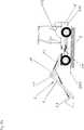
Das Lade- und Baggergerät
Am Vorderwagen
Der Hubarm
Der Arbeitsbereich dieser am Schnellwechsler
Zum Anheben beim Schwenken des Hubarmes
Zum Schwenken, insbesondere zum Anheben, des Zwischenarms
Zum Schwenken, insbesondere zum Anheben, des Werkzeugträgers
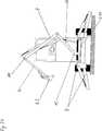
Das Lade- und Baggergerät
Das Lade- und Baggergerät
Am Vorderwagen
Zum Anheben beim Schwenken des Zusatzarms
Der Grundkörper des Zusatzarms
Der Zusatzarms
Der Hubarm
Zum Anheben beim Schwenken des Hubarmes
Zum Schwenken, insbesondere zum Anheben, des Zwischenarms
Zum Schwenken, insbesondere zum Anheben, des Werkzeugträgers
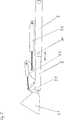
In
Das Lade- und Baggergerät gemäß der zweiten Anordnung, dargestellt in
Zum Anheben beim Schwenken des Zusatzarms
Der Grundkörper des Zusatzarms
Der Hubarm
Zum Schwenken, insbesondere zum Anheben, des Werkzeugträgers
BezugszeichenlisteLIST OF REFERENCE NUMBERS
- 11
- Lade- und BaggergerätLoading and digging device
- 1.11.1
- Fahrwerklanding gear
- 1.111.11
- Vorderwagenfront end
- 1.121.12
- Hinterwagenrear car
- 1.131.13
- Fahrersitzdriver's seat
- 22
- Auslegerboom
- 33
- Schwenkwerkslewing
- 44
- Hubarmlifting arm
- 4.14.1
- Anschlagattack
- 55
- Werkzeugträgertool carrier
- 5.15.1
- SchnellwechslerQuick coupler
- 66
- Anbau-WerkzeugeFarming tools
- 6.16.1
- Ladeschaufelnbuckets
- 6.26.2
- BaggerlöffelBaggerlöffel
- 6.36.3
- Greifergrab
- 77
- Zusatzarmadditional arm
- 88th
- Stützeinrichtungensupport devices
- 99
- Hubvorrichtunglifting device
- 9.1, 9.2, 9.39.1, 9.2, 9.3
- Hydraulische HubvorrichtungHydraulic lifting device
- 1010
- Zwischenarmintermediate arm
- 1111
- Verbindung, lösbarConnection, detachable
- 1212
- Gelenkverbindungarticulation
ZITATE ENTHALTEN IN DER BESCHREIBUNG QUOTES INCLUDE IN THE DESCRIPTION
Diese Liste der vom Anmelder aufgeführten Dokumente wurde automatisiert erzeugt und ist ausschließlich zur besseren Information des Lesers aufgenommen. Die Liste ist nicht Bestandteil der deutschen Patent- bzw. Gebrauchsmusteranmeldung. Das DPMA übernimmt keinerlei Haftung für etwaige Fehler oder Auslassungen.This list of the documents listed by the applicant has been generated automatically and is included solely for the better information of the reader. The list is not part of the German patent or utility model application. The DPMA assumes no liability for any errors or omissions.
Zitierte PatentliteraturCited patent literature
- DE 3611432 C2[0004]DE 3611432 C2[0004]
Claims (10)
Translated fromGermanPriority Applications (1)
| Application Number | Priority Date | Filing Date | Title |
|---|---|---|---|
| DE201110102062DE102011102062A1 (en) | 2011-05-19 | 2011-05-19 | Boom for universal farm loader that is utilized in e.g. gardens to drive cargo, has tool carrier arranged at vertically pivotable lifting arm, and swingable intermediate arm steered between horizontally pivotable swing gear and lift arm |
Applications Claiming Priority (1)
| Application Number | Priority Date | Filing Date | Title |
|---|---|---|---|
| DE201110102062DE102011102062A1 (en) | 2011-05-19 | 2011-05-19 | Boom for universal farm loader that is utilized in e.g. gardens to drive cargo, has tool carrier arranged at vertically pivotable lifting arm, and swingable intermediate arm steered between horizontally pivotable swing gear and lift arm |
Publications (1)
| Publication Number | Publication Date |
|---|---|
| DE102011102062A1true DE102011102062A1 (en) | 2012-11-22 |
Family
ID=47088129
Family Applications (1)
| Application Number | Title | Priority Date | Filing Date |
|---|---|---|---|
| DE201110102062WithdrawnDE102011102062A1 (en) | 2011-05-19 | 2011-05-19 | Boom for universal farm loader that is utilized in e.g. gardens to drive cargo, has tool carrier arranged at vertically pivotable lifting arm, and swingable intermediate arm steered between horizontally pivotable swing gear and lift arm |
Country Status (1)
| Country | Link |
|---|---|
| DE (1) | DE102011102062A1 (en) |
Cited By (1)
| Publication number | Priority date | Publication date | Assignee | Title |
|---|---|---|---|---|
| US9267262B2 (en) | 2014-06-06 | 2016-02-23 | Caterpillar Sarl | Lift arm linkage with extension cylinder |
Citations (8)
| Publication number | Priority date | Publication date | Assignee | Title |
|---|---|---|---|---|
| DE3611432C2 (en) | 1986-04-05 | 1991-08-01 | Karl Schaeff Gmbh & Co, Maschinenfabrik, 7183 Langenburg, De | |
| WO1993007342A1 (en)* | 1991-10-08 | 1993-04-15 | Raunisto, Airi | A driving machine with an articulated boom |
| EP0595614A1 (en)* | 1992-10-29 | 1994-05-04 | Japanic Corporation | Telescopic arm for grab bucket excavator |
| WO1997020998A1 (en)* | 1995-12-05 | 1997-06-12 | Blom, Andreas | Arm arrangement of a lifting device |
| DE20120964U1 (en)* | 2001-12-27 | 2003-06-12 | Liebherr-Hydraulikbagger GmbH, 88457 Kirchdorf | Support device for construction machines such as hydraulic excavators and the like. |
| DE202004007421U1 (en)* | 2004-05-06 | 2004-12-16 | Schmidt, Helmut | Improved design for front loader has two linked arms mounted on a swivel plate and with two working cylinders to extend the reach of the operation and to retract into a compact and stable position for moving over uneven ground |
| DE10346413A1 (en)* | 2003-10-07 | 2005-05-04 | Deere & Co | Loading device, especially front loader for loader vehicle, has telescopic jibs which can be pivoted, extended and retracted independently |
| DE102008026173A1 (en)* | 2008-06-01 | 2009-12-03 | Technische Universität Dresden | Foldable working boom for multi-purpose vehicle for e.g. transport-operation, has additional arm coupled to primary arm, where tool is attached to main arm or other tool is attached to folded additional arm |
- 2011
- 2011-05-19DEDE201110102062patent/DE102011102062A1/ennot_activeWithdrawn
Patent Citations (8)
| Publication number | Priority date | Publication date | Assignee | Title |
|---|---|---|---|---|
| DE3611432C2 (en) | 1986-04-05 | 1991-08-01 | Karl Schaeff Gmbh & Co, Maschinenfabrik, 7183 Langenburg, De | |
| WO1993007342A1 (en)* | 1991-10-08 | 1993-04-15 | Raunisto, Airi | A driving machine with an articulated boom |
| EP0595614A1 (en)* | 1992-10-29 | 1994-05-04 | Japanic Corporation | Telescopic arm for grab bucket excavator |
| WO1997020998A1 (en)* | 1995-12-05 | 1997-06-12 | Blom, Andreas | Arm arrangement of a lifting device |
| DE20120964U1 (en)* | 2001-12-27 | 2003-06-12 | Liebherr-Hydraulikbagger GmbH, 88457 Kirchdorf | Support device for construction machines such as hydraulic excavators and the like. |
| DE10346413A1 (en)* | 2003-10-07 | 2005-05-04 | Deere & Co | Loading device, especially front loader for loader vehicle, has telescopic jibs which can be pivoted, extended and retracted independently |
| DE202004007421U1 (en)* | 2004-05-06 | 2004-12-16 | Schmidt, Helmut | Improved design for front loader has two linked arms mounted on a swivel plate and with two working cylinders to extend the reach of the operation and to retract into a compact and stable position for moving over uneven ground |
| DE102008026173A1 (en)* | 2008-06-01 | 2009-12-03 | Technische Universität Dresden | Foldable working boom for multi-purpose vehicle for e.g. transport-operation, has additional arm coupled to primary arm, where tool is attached to main arm or other tool is attached to folded additional arm |
Cited By (1)
| Publication number | Priority date | Publication date | Assignee | Title |
|---|---|---|---|---|
| US9267262B2 (en) | 2014-06-06 | 2016-02-23 | Caterpillar Sarl | Lift arm linkage with extension cylinder |
Similar Documents
| Publication | Publication Date | Title |
|---|---|---|
| DE2521804C2 (en) | Vehicle with counterweight | |
| DE2414066A1 (en) | MATERIAL TRANSPORT DEVICE | |
| DE4341313C1 (en) | Combination of an excavator with a trailer | |
| DE7338262U (en) | AGRICULTURAL MACHINE | |
| EP0273400A1 (en) | Supporting and clearing blade for an excavator | |
| DE202014004566U1 (en) | Lifting device for coupling to the changing devices of Hofladern, front loaders and three-point linkage to increase the lifting height of the implements | |
| DE69708361T2 (en) | Self loading wagon with loading arm | |
| DE2013849A1 (en) | Backhoe | |
| WO1999035344A1 (en) | Mobile loading machine with front loading equipment | |
| DE102011102062A1 (en) | Boom for universal farm loader that is utilized in e.g. gardens to drive cargo, has tool carrier arranged at vertically pivotable lifting arm, and swingable intermediate arm steered between horizontally pivotable swing gear and lift arm | |
| AT11609U1 (en) | HARVESTER | |
| DE202011100922U1 (en) | Boom for a loader and digger | |
| DE202008002254U1 (en) | Shovel for a wheel loader or farm loader | |
| DE1935432B2 (en) | GRIPPING DEVICE FOR LONG WOOD | |
| DE2027259B2 (en) | Loading and unloading device for containers or the like. on vehicles | |
| EP1462306B1 (en) | Working vehicle with loading and transport capabilities | |
| DE3227136A1 (en) | Loading and excavating machine | |
| DE10033920A1 (en) | Working vehicle with jib, e.g. digger truck or dredger, has work implement and jib operated by hydraulically connected lifting and tilt cylinders | |
| DE102009052907B4 (en) | Device and method for moving a bed | |
| DE202010000352U1 (en) | attachment | |
| DE1484704A1 (en) | Mobile charger, especially for earthworks or the like. | |
| DE10025596A1 (en) | Accessory device for lifting objects such as root balls, large stones and suchlike has shovels pivot-mounted on shovel support hinged to pivot around horizontal axis by at least 90 degrees | |
| DE202009010405U1 (en) | Material handling machine | |
| DE102009058836A1 (en) | Mobile hydraulic excavator for use in e.g. building sites or quarries, has excavator arm including boom and handle for receiving attachment, where handle includes transport device for receiving another attachment | |
| DE102010010218B4 (en) | Combined fork and plow blade device for agricultural vehicles |
Legal Events
| Date | Code | Title | Description |
|---|---|---|---|
| R012 | Request for examination validly filed | ||
| R016 | Response to examination communication | ||
| R120 | Application withdrawn or ip right abandoned | Effective date:20131128 |