DE102011086206A1 - Arrangement for determining spectral characteristics of boring fluid under influence of high temperature and mechanical loads at place of occurrence of fluid, has source for polychromatic electromagnetic radiation source and optical unit - Google Patents
Arrangement for determining spectral characteristics of boring fluid under influence of high temperature and mechanical loads at place of occurrence of fluid, has source for polychromatic electromagnetic radiation source and optical unitDownload PDFInfo
- Publication number
- DE102011086206A1 DE102011086206A1DE201110086206DE102011086206ADE102011086206A1DE 102011086206 A1DE102011086206 A1DE 102011086206A1DE 201110086206DE201110086206DE 201110086206DE 102011086206 ADE102011086206 ADE 102011086206ADE 102011086206 A1DE102011086206 A1DE 102011086206A1
- Authority
- DE
- Germany
- Prior art keywords
- arrangement according
- fluid
- grating
- spectrometer
- electromagnetic radiation
- Prior art date
- Legal status (The legal status is an assumption and is not a legal conclusion. Google has not performed a legal analysis and makes no representation as to the accuracy of the status listed.)
- Ceased
Links
- 239000012530fluidSubstances0.000titleclaimsabstractdescription30
- 230000005670electromagnetic radiationEffects0.000titleclaimsabstractdescription14
- 230000003287optical effectEffects0.000titleclaimsabstractdescription6
- 230000003595spectral effectEffects0.000titleclaimsdescription6
- 239000000463materialSubstances0.000claimsabstractdescription9
- 230000005855radiationEffects0.000claimsabstractdescription7
- 239000004696Poly ether ether ketoneSubstances0.000claimsabstractdescription6
- 229920002530polyetherether ketonePolymers0.000claimsabstractdescription6
- 239000000758substrateSubstances0.000claimsabstractdescription5
- 229910001030Iron–nickel alloyInorganic materials0.000claimsabstractdescription3
- 238000005553drillingMethods0.000claimsdescription12
- 238000003384imaging methodMethods0.000claimsdescription10
- VYPSYNLAJGMNEJ-UHFFFAOYSA-NSilicium dioxideChemical compoundO=[Si]=OVYPSYNLAJGMNEJ-UHFFFAOYSA-N0.000claimsdescription9
- PXHVJJICTQNCMI-UHFFFAOYSA-NNickelChemical compound[Ni]PXHVJJICTQNCMI-UHFFFAOYSA-N0.000claimsdescription8
- 238000011156evaluationMethods0.000claimsdescription7
- 229910052594sapphireInorganic materials0.000claimsdescription7
- 239000010980sapphireSubstances0.000claimsdescription7
- 239000002184metalSubstances0.000claimsdescription6
- 229910052751metalInorganic materials0.000claimsdescription6
- 229910000530Gallium indium arsenideInorganic materials0.000claimsdescription5
- 238000010183spectrum analysisMethods0.000claimsdescription5
- 229910052759nickelInorganic materials0.000claimsdescription4
- 239000003129oil wellSubstances0.000claimsdescription4
- 229930195733hydrocarbonNatural products0.000claimsdescription3
- 150000002430hydrocarbonsChemical class0.000claimsdescription3
- 239000004215Carbon black (E152)Substances0.000claimsdescription2
- 238000001228spectrumMethods0.000claimsdescription2
- 239000011248coating agentSubstances0.000claims4
- 238000000576coating methodMethods0.000claims4
- 239000000523sampleSubstances0.000description19
- 238000004458analytical methodMethods0.000description13
- 239000010779crude oilSubstances0.000description9
- 238000000034methodMethods0.000description6
- 239000011435rockSubstances0.000description6
- 230000001133accelerationEffects0.000description4
- 235000012239silicon dioxideNutrition0.000description4
- 238000012360testing methodMethods0.000description4
- 238000005259measurementMethods0.000description3
- 239000003921oilSubstances0.000description3
- 239000010453quartzSubstances0.000description3
- 230000035939shockEffects0.000description3
- 230000004075alterationEffects0.000description2
- 238000013461designMethods0.000description2
- 238000000605extractionMethods0.000description2
- 238000011835investigationMethods0.000description2
- 238000005070samplingMethods0.000description2
- 230000035945sensitivityEffects0.000description2
- 238000012546transferMethods0.000description2
- BUHVIAUBTBOHAG-FOYDDCNASA-N(2r,3r,4s,5r)-2-[6-[[2-(3,5-dimethoxyphenyl)-2-(2-methylphenyl)ethyl]amino]purin-9-yl]-5-(hydroxymethyl)oxolane-3,4-diolChemical compoundCOC1=CC(OC)=CC(C(CNC=2C=3N=CN(C=3N=CN=2)[C@H]2[C@@H]([C@H](O)[C@@H](CO)O2)O)C=2C(=CC=CC=2)C)=C1BUHVIAUBTBOHAG-FOYDDCNASA-N0.000description1
- 229910004298SiO 2Inorganic materials0.000description1
- 238000010521absorption reactionMethods0.000description1
- 238000004847absorption spectroscopyMethods0.000description1
- 239000000853adhesiveSubstances0.000description1
- 230000001070adhesive effectEffects0.000description1
- 238000013459approachMethods0.000description1
- 230000015572biosynthetic processEffects0.000description1
- 239000000919ceramicSubstances0.000description1
- 238000011109contaminationMethods0.000description1
- 238000001816coolingMethods0.000description1
- 238000007405data analysisMethods0.000description1
- 238000011161developmentMethods0.000description1
- 238000005530etchingMethods0.000description1
- 230000002349favourable effectEffects0.000description1
- 125000000524functional groupChemical group0.000description1
- 239000005350fused silica glassSubstances0.000description1
- 239000011521glassSubstances0.000description1
- 238000011065in-situ storageMethods0.000description1
- 230000010354integrationEffects0.000description1
- 239000004922lacquerSubstances0.000description1
- 238000004519manufacturing processMethods0.000description1
- 230000037361pathwayEffects0.000description1
- 230000002093peripheral effectEffects0.000description1
- 238000002360preparation methodMethods0.000description1
- 238000011158quantitative evaluationMethods0.000description1
- 239000011347resinSubstances0.000description1
- 229920005989resinPolymers0.000description1
- 229910010271silicon carbideInorganic materials0.000description1
- HBMJWWWQQXIZIP-UHFFFAOYSA-Nsilicon carbideChemical compound[Si+]#[C-]HBMJWWWQQXIZIP-UHFFFAOYSA-N0.000description1
- 239000000377silicon dioxideSubstances0.000description1
Images

Classifications
- E—FIXED CONSTRUCTIONS
- E21—EARTH OR ROCK DRILLING; MINING
- E21B—EARTH OR ROCK DRILLING; OBTAINING OIL, GAS, WATER, SOLUBLE OR MELTABLE MATERIALS OR A SLURRY OF MINERALS FROM WELLS
- E21B49/00—Testing the nature of borehole walls; Formation testing; Methods or apparatus for obtaining samples of soil or well fluids, specially adapted to earth drilling or wells
- E21B49/08—Obtaining fluid samples or testing fluids, in boreholes or wells
- E21B49/087—Well testing, e.g. testing for reservoir productivity or formation parameters
- E21B49/0875—Well testing, e.g. testing for reservoir productivity or formation parameters determining specific fluid parameters
- G—PHYSICS
- G01—MEASURING; TESTING
- G01J—MEASUREMENT OF INTENSITY, VELOCITY, SPECTRAL CONTENT, POLARISATION, PHASE OR PULSE CHARACTERISTICS OF INFRARED, VISIBLE OR ULTRAVIOLET LIGHT; COLORIMETRY; RADIATION PYROMETRY
- G01J3/00—Spectrometry; Spectrophotometry; Monochromators; Measuring colours
- G01J3/02—Details
- G01J3/0291—Housings; Spectrometer accessories; Spatial arrangement of elements, e.g. folded path arrangements
- G—PHYSICS
- G01—MEASURING; TESTING
- G01J—MEASUREMENT OF INTENSITY, VELOCITY, SPECTRAL CONTENT, POLARISATION, PHASE OR PULSE CHARACTERISTICS OF INFRARED, VISIBLE OR ULTRAVIOLET LIGHT; COLORIMETRY; RADIATION PYROMETRY
- G01J3/00—Spectrometry; Spectrophotometry; Monochromators; Measuring colours
- G01J3/02—Details
- G01J3/0202—Mechanical elements; Supports for optical elements
- G—PHYSICS
- G01—MEASURING; TESTING
- G01J—MEASUREMENT OF INTENSITY, VELOCITY, SPECTRAL CONTENT, POLARISATION, PHASE OR PULSE CHARACTERISTICS OF INFRARED, VISIBLE OR ULTRAVIOLET LIGHT; COLORIMETRY; RADIATION PYROMETRY
- G01J3/00—Spectrometry; Spectrophotometry; Monochromators; Measuring colours
- G01J3/02—Details
- G01J3/0205—Optical elements not provided otherwise, e.g. optical manifolds, diffusers, windows
- G01J3/0208—Optical elements not provided otherwise, e.g. optical manifolds, diffusers, windows using focussing or collimating elements, e.g. lenses or mirrors; performing aberration correction
- G—PHYSICS
- G01—MEASURING; TESTING
- G01J—MEASUREMENT OF INTENSITY, VELOCITY, SPECTRAL CONTENT, POLARISATION, PHASE OR PULSE CHARACTERISTICS OF INFRARED, VISIBLE OR ULTRAVIOLET LIGHT; COLORIMETRY; RADIATION PYROMETRY
- G01J3/00—Spectrometry; Spectrophotometry; Monochromators; Measuring colours
- G01J3/02—Details
- G01J3/0205—Optical elements not provided otherwise, e.g. optical manifolds, diffusers, windows
- G01J3/021—Optical elements not provided otherwise, e.g. optical manifolds, diffusers, windows using plane or convex mirrors, parallel phase plates, or particular reflectors
- G—PHYSICS
- G01—MEASURING; TESTING
- G01J—MEASUREMENT OF INTENSITY, VELOCITY, SPECTRAL CONTENT, POLARISATION, PHASE OR PULSE CHARACTERISTICS OF INFRARED, VISIBLE OR ULTRAVIOLET LIGHT; COLORIMETRY; RADIATION PYROMETRY
- G01J3/00—Spectrometry; Spectrophotometry; Monochromators; Measuring colours
- G01J3/02—Details
- G01J3/0286—Constructional arrangements for compensating for fluctuations caused by temperature, humidity or pressure, or using cooling or temperature stabilization of parts of the device; Controlling the atmosphere inside a spectrometer, e.g. vacuum
- G—PHYSICS
- G01—MEASURING; TESTING
- G01J—MEASUREMENT OF INTENSITY, VELOCITY, SPECTRAL CONTENT, POLARISATION, PHASE OR PULSE CHARACTERISTICS OF INFRARED, VISIBLE OR ULTRAVIOLET LIGHT; COLORIMETRY; RADIATION PYROMETRY
- G01J3/00—Spectrometry; Spectrophotometry; Monochromators; Measuring colours
- G01J3/12—Generating the spectrum; Monochromators
- G01J3/18—Generating the spectrum; Monochromators using diffraction elements, e.g. grating
- G—PHYSICS
- G01—MEASURING; TESTING
- G01N—INVESTIGATING OR ANALYSING MATERIALS BY DETERMINING THEIR CHEMICAL OR PHYSICAL PROPERTIES
- G01N21/00—Investigating or analysing materials by the use of optical means, i.e. using sub-millimetre waves, infrared, visible or ultraviolet light
- G01N21/17—Systems in which incident light is modified in accordance with the properties of the material investigated
- G01N21/25—Colour; Spectral properties, i.e. comparison of effect of material on the light at two or more different wavelengths or wavelength bands
- G01N21/31—Investigating relative effect of material at wavelengths characteristic of specific elements or molecules, e.g. atomic absorption spectrometry
- G01N21/35—Investigating relative effect of material at wavelengths characteristic of specific elements or molecules, e.g. atomic absorption spectrometry using infrared light
- G01N21/3577—Investigating relative effect of material at wavelengths characteristic of specific elements or molecules, e.g. atomic absorption spectrometry using infrared light for analysing liquids, e.g. polluted water
- G—PHYSICS
- G01—MEASURING; TESTING
- G01N—INVESTIGATING OR ANALYSING MATERIALS BY DETERMINING THEIR CHEMICAL OR PHYSICAL PROPERTIES
- G01N21/00—Investigating or analysing materials by the use of optical means, i.e. using sub-millimetre waves, infrared, visible or ultraviolet light
- G01N21/17—Systems in which incident light is modified in accordance with the properties of the material investigated
- G01N21/25—Colour; Spectral properties, i.e. comparison of effect of material on the light at two or more different wavelengths or wavelength bands
- G01N21/31—Investigating relative effect of material at wavelengths characteristic of specific elements or molecules, e.g. atomic absorption spectrometry
- G01N21/35—Investigating relative effect of material at wavelengths characteristic of specific elements or molecules, e.g. atomic absorption spectrometry using infrared light
- G01N21/359—Investigating relative effect of material at wavelengths characteristic of specific elements or molecules, e.g. atomic absorption spectrometry using infrared light using near infrared light
- E—FIXED CONSTRUCTIONS
- E21—EARTH OR ROCK DRILLING; MINING
- E21B—EARTH OR ROCK DRILLING; OBTAINING OIL, GAS, WATER, SOLUBLE OR MELTABLE MATERIALS OR A SLURRY OF MINERALS FROM WELLS
- E21B47/00—Survey of boreholes or wells
- E21B47/01—Devices for supporting measuring instruments on drill bits, pipes, rods or wirelines; Protecting measuring instruments in boreholes against heat, shock, pressure or the like
- E21B47/017—Protecting measuring instruments
Landscapes
- Physics & Mathematics (AREA)
- Spectroscopy & Molecular Physics (AREA)
- General Physics & Mathematics (AREA)
- Life Sciences & Earth Sciences (AREA)
- Mining & Mineral Resources (AREA)
- Geology (AREA)
- Engineering & Computer Science (AREA)
- Chemical & Material Sciences (AREA)
- General Health & Medical Sciences (AREA)
- Immunology (AREA)
- Pathology (AREA)
- Biochemistry (AREA)
- Environmental & Geological Engineering (AREA)
- Fluid Mechanics (AREA)
- Analytical Chemistry (AREA)
- Health & Medical Sciences (AREA)
- General Life Sciences & Earth Sciences (AREA)
- Geochemistry & Mineralogy (AREA)
- Investigating Or Analysing Materials By Optical Means (AREA)
Abstract
Description
Translated fromGermanDie Erfindung bezieht sich auf eine Anordnung zum Bestimmen spektraler Eigenschaften von Bohrlochfluiden bei der Erdölförderung unter dem Einfluss hoher Temperatur- und mechanischer Belastungen am Ort ihres Vorkommens im Bohrloch.The invention relates to an arrangement for determining the spectral properties of borehole fluids in oil production under the influence of high temperature and mechanical stresses at the point of their occurrence in the borehole.
Erdöl wird heute aus Erdschichten gefördert, die vor wenigen Jahren aus technischen Gründen noch unerreichbar waren. Es sind verschiedene Vorgehensweisen bekannt, um bereits während der Erkundung Informationen über das durchbohrte Gestein und die zu erwartende Qualität des Erdöls zu gewinnen, insbesondere anhand spektrometrischer Untersuchungen. Konventionell wird das Bohrloch abschnittsweise oder auch vollständig gebohrt, ohne diesbezüglich schon während des Bohrens detaillierte Messungen vorzunehmen.Today crude oil is extracted from layers of earth that were unavailable for technical reasons just a few years ago. There are several known ways of obtaining information about the drilled rock and the expected quality of the oil during exploration, especially from spectrometric investigations. Conventionally, the borehole is drilled in sections or even completely, without taking detailed measurements during drilling.
Um die zu erwartende Qualität des Erdöls dennoch bewerten zu können, werden Bohrkerne und auch Rohölproben an die Oberfläche gebracht. Dazu muss zeit- und kostenaufwändig das Bohrgestänge aus dem Bohrloch herausgezogen werden. Die spektrometrischen Untersuchungen des aus dem Bohrloch geförderten Materials, insbesondere die Auswertung der Absorptionsbanden verschiedener Kohlenwasserstoffe im infraroten Spektralbereich, ermöglichen die Bewertung der verschiedenen Rohölqualitäten. Nachteilig ist auch, dass jede Rohölprobe in einem Probebehälter unter dem Druck vorgehalten werden muss, unter dem sie in der Tiefe entnommen wurde, und so zu einem Analyseort transportiert werden muss.Nevertheless, in order to be able to evaluate the expected quality of the oil, drilling cores and also crude oil samples are brought to the surface. For this purpose, the drill string has to be pulled out of the borehole in a time- and cost-consuming manner. The spectrometric investigations of the material extracted from the borehole, in particular the evaluation of the absorption bands of various hydrocarbons in the infrared spectral range, make it possible to evaluate the different crude oil qualities. Another disadvantage is that each crude oil sample must be kept in a sample container under the pressure under which it was taken in depth, and thus has to be transported to a place of analysis.
Bei einer Weiterentwicklung der vorgenannten Verfahrensweise wird eine Messsonde in das Bohrloch hinabgelassen, die vorzugsweise über ein Kabel mit Auswerteeinrichtungen an der Erdoberfläche verbunden ist. Diese Vorgehensweise bietet zwar die Möglichkeit, die Sonde in der Tiefe mit Energie zu versorgen und gewährleistet eine schnelle Datenübertragung nach oben einschließlich schneller Datenauswertung, jedoch muss hier ebenfalls zunächst der Bohrer aus dem Bohrloch herausgezogen werden. Außerdem besteht die Gefahr der Beschädigung der Messsonde, da sie den hohen Temperaturen im Bohrloch ausgesetzt ist.In a further development of the aforementioned procedure, a measuring probe is lowered into the borehole, which is preferably connected via a cable with evaluation devices on the earth's surface. Although this approach provides the ability to power the depth of the probe and ensures fast data transfer, including fast data analysis, it is also important to first pull the drill out of the hole. In addition, there is a risk of damage to the probe, as it is exposed to the high temperatures in the borehole.
In
Aus
In neueren Verfahren wird versucht, eine Analyseeinrichtung in die ersten Meter des Bohrgestänges zu integrieren. Dies hat im Vergleich zu der vorgenannten Verfahrensweise nicht nur den Vorteil, dass die Eigenschaften der durchbohrten Gesteinsschichten und des Rohöls bereits während des Bohrvorgangs ermittelt werden können und das Herausziehen des Bohrgestänges entfällt, sondern auch den Vorzug, dass die zur Kühlung des Bohrkopfes genutzte Bohrflüssigkeit zugleich auch die Analyseeinrichtung kühlt.More recent methods attempt to integrate an analysis device into the first meters of the drill string. This has in comparison to the above procedure not only the advantage that the properties of the drilled rock layers and crude oil can be determined during the drilling process and eliminating the extraction of the drill string deleted, but also the advantage that the used for cooling the drill bit drilling fluid at the same time also the analysis device cools.
Weiterhin verringern sich hierdurch auch die Kosten für die Entnahme und Analyse der Probe, da die Messung bei den hohen Drücken vor Ort erfolgt und es nicht mehr erforderlich ist, Probenbehälter, in denen die Probe unter Druck vorgehalten wird, aus dem Bohrloch heraus und zu einem Analyseort zu transportieren. Außerdem ist es auf diese Weise möglich, Proben weitestgehend ohne Verschmutzung durch Bohrflüssigkeit zu analysieren und damit zu genaueren Aussagen bezüglich der Qualität zu kommen.Furthermore, this also reduces the cost of taking and analyzing the sample, since the measurement takes place at the high pressures in the field and it is no longer necessary, sample container in which the sample is held under pressure, out of the well and to a Transport analysis site. In addition, it is possible in this way to analyze samples as far as possible without contamination by drilling fluid and thus come to more accurate statements about the quality.
Allerdings sind die hierzu erforderlichen Analyseeinrichtungen neben den hohen Temperaturen und Drücken in der Tiefe zusätzlich hohen mechanischen Belastungen aufgrund der während des Bohrens unvermeidlich auftretenden Beschleunigungen, Schwingungen und Stößen ausgesetzt.However, in addition to the high temperatures and pressures at depth, the analytical devices required for this purpose are additionally exposed to high mechanical loads due to the accelerations, vibrations and impacts that inevitably occur during drilling.
Insofern besteht im einschlägigen technischen Gebiet das Bedürfnis nach Analyseeinrichtungen, die unter der Bedingung von Temperaturen im Bereich von 150°C bis 200°C sowie unter den genannten mechanischen Belastungen eine spektrometrisch wellenlängenkorrekte Analyse des Rohöls während des Bohrens ermöglichen.In this respect, there is a need in the pertinent technical field for analysis devices which permit a spectrometrically wavelength-correct analysis of the crude oil during drilling under the condition of temperatures in the range of 150 ° C. to 200 ° C. and under said mechanical loads.
Ein Spektrometer, das diesen extremen Anforderungen genügt, ist aus dem derzeitigen Stand der Technik nicht bekannt.A spectrometer that meets these extreme requirements is not known in the current state of the art.
Davon ausgehend besteht die Aufgabe der Erfindung darin, eine Messanordnung der eingangs beschriebenen Art so weiterzubilden, dass auch bei Arbeitstemperaturen von 150°C bis 200°C und mechanischen Belastungen aufgrund extremer Drücke, Beschleunigungen, Schwingungen und Stöße eine spektrometrisch wellenlängenkorrekte Materialanalyse, insbesondere von Rohöl während des Bohrens, möglich ist. On this basis, the object of the invention is to develop a measuring arrangement of the type described above so that even at working temperatures of 150 ° C to 200 ° C and mechanical stresses due to extreme pressures, accelerations, vibrations and shocks spectrometrically wavelength-correct material analysis, especially of crude oil while drilling is possible.
Diese Aufgabe wird gelöst mit einer Anordnung zum Bestimmen spektraler Eigenschaften eines Bohrlochfluids, umfassend
- – eine Quelle für polychromatische elektromagnetische Strahlung,
- – eine Probenkammer mit dem Fluid,
- – optische Mittel zur Ausrichtung der elektromagnetischen Strahlung auf das Fluid, und
- – eine Spektralanalyse-Einrichtung in Form eines Gitterspektrometers, ausgebildet zum Detektieren des Spektrums der vom Fluid transmittierten oder gestreuten elektromagnetischen Strahlung, wobei
- − das Gitterspektrometer ein Original-Gitter mit einer auf Strahlungswellenlängen λ im Bereich von 200 nm bis 4000 nm abgestimmten Gitterperiode aufweist.
- - a source of polychromatic electromagnetic radiation,
- A sample chamber with the fluid,
- - Optical means for aligning the electromagnetic radiation to the fluid, and
- A spectral analysis device in the form of a grating spectrometer, designed to detect the spectrum of the electromagnetic radiation transmitted or scattered by the fluid, wherein
- - The grating spectrometer has an original grating with a tuned to radiation wavelengths λ in the range of 200 nm to 4000 nm grating period.
Die Ausführung des Gitters als Original-Gitter hat im Vergleich zum Einsatz von Replica den Vorteil der höheren Stabilität des Gitters unter den hohen Arbeitstemperaturen, denen das Spektrometer ausgesetzt ist, während bei den Gitterkopien die Gitterstrukturen aus Lack, Harz oder ähnlichen Materialien bereits bei wesentlich niedrigeren Temperaturen verbrennen oder das für höchste Beugungseffizienz optimierte Gitterprofil sich in einer für die vorgesehene Anwendung unvorteilhaften Art verändert.The design of the lattice as an original lattice has the advantage of higher stability of the lattice under the high operating temperatures to which the spectrometer is exposed compared to the use of replica, while in the lattice copies the lattice structures of lacquer, resin or similar materials already at much lower Burn temperatures or optimized for maximum diffraction efficiency grating profile changed in a disadvantageous for the intended application type.
In einer bevorzugten Ausführungsform der Erfindung ist die Gitterstruktur in die Oberfläche eines Trägers aus Quarzglas eingebracht. Unter Quarzglas (engl.: fused silica) im Sinne der Erfindung ist Siliziumdioxid (SiO2) in amorphem Gefüge zu verstehen – im Unterschied zu dem kristallinen Quarz (engl.: quartz).In a preferred embodiment of the invention, the grid structure is introduced into the surface of a carrier made of quartz glass. For the purposes of the invention, fused silica means silicon dioxide (SiO 2) in an amorphous structure, in contrast to crystalline quartz (quartz).
In alternativen Ausführungsformen dient Metall als Substrat für die Gitterstruktur. Bevorzugt kommt erfindungsgemäß eine Eisen-Nickel-Legierung in Betracht, da diese einen besonders günstigen Wärmeausdehnungskoeffizienten (Coefficient of Thermal Expansion, CTE) hat. Optional kann die Gitterstruktur auch in Nickel oder in eine Nickelschicht eingebracht sein.In alternative embodiments, metal serves as a substrate for the lattice structure. According to the invention, preference is given to an iron-nickel alloy, since this has a particularly favorable coefficient of thermal expansion (CTE). Optionally, the grid structure may also be incorporated in nickel or in a nickel layer.
In einer weiteren alternativen Ausführungsform ist ein Polyetheretherketon-Werkstoff (PEEK) als Substrat für die Gitterstruktur vorgesehen. Polyetheretherketone besitzen neben einer sehr guten Temperaturfestigkeit auch mechanische Eigenschaften wie hohe Festigkeit und hohe Steifigkeit, die im Zusammenhang mit den Einsatzbedingungen der erfindungsgemäßen Anordnung von Vorteil sind.In a further alternative embodiment, a polyetheretherketone material (PEEK) is provided as a substrate for the lattice structure. Polyetheretherketones not only have very good temperature resistance but also mechanical properties such as high strength and high rigidity, which are advantageous in connection with the conditions of use of the arrangement according to the invention.
Das Gitter ist bevorzugt als abbildendes, konkaves Reflexionsgitter mit geblaztem Oberflächenprofil ausgeführt. Die Herstellung erfolgt bevorzugt durch holographische Belichtung und anschließende Übertragung des Profils mittels Ätzen in die Quarzglasoberfläche.The grating is preferably designed as an imaging, concave reflection grating with a blazed surface profile. The preparation is preferably carried out by holographic exposure and subsequent transfer of the profile by means of etching in the quartz glass surface.
Mit dem geblazten Gitterprofil werden besonders hohe Effizienzen erzielt. Das abbildende Gitter ermöglicht vorteilhaft eine besonders kompakte Bauweise bei großer numerischer Apertur und damit hohem Lichtleitwert, also großer Empfindlichkeit und gleichzeitig geringen Abbildungsfehlern – respektive einer hohen Auflösung.The blazed grid profile achieves particularly high efficiencies. The imaging grating advantageously allows a particularly compact design with a large numerical aperture and thus high light conductance, ie high sensitivity and simultaneously low aberrations - respectively a high resolution.
Eine Ausführung als mechanisch geteiltes planares Gitter liegt jedoch ebenfalls im Rahmen der Erfindung.However, an embodiment as a mechanically divided planar grid is also within the scope of the invention.
Der Grundkörper des Spektrometers ist bevorzugt monolithisch ausgeführt, so dass CTE-Unterschiede zwischen verschiedenen Komponenten vermieden und eine optimale Temperaturstabilität des Spektrometers erzielt wird. Ein monolithischer Aufbau bietet zudem höchste mechanische Stabilität bei extremen Beschleunigungen, Vibrationen und Stößen. Des weiteren erlaubt ein monolithischer Aufbau, höchste Performance in minimalem Bauraum zu realisieren.The basic body of the spectrometer is preferably monolithic, so that CTE differences between different components are avoided and optimum temperature stability of the spectrometer is achieved. A monolithic structure also offers maximum mechanical stability under extreme accelerations, vibrations and shocks. Furthermore, a monolithic structure allows to realize maximum performance in a minimum space.
Die erfindungsgemäße Anordnung ist bevorzugt mit einem Detektor auf Basis von InGaAs-Sensoren ausgestattet. Vorteilhaft werden dabei eine Zeile bzw. ein Array aus InGaAs-Sensoren mit exakt ausgemessenem Abstand zwischen Sensor-Chip und dem Chip-Träger verwendet und dieses Abstandsmaß bei der Abmessung des Grundkörpers so berücksichtigt, dass eine optimale Auflösung des Gitterspektrometers erzielt wird.The arrangement according to the invention is preferably equipped with a detector based on InGaAs sensors. Advantageously, a row or an array of InGaAs sensors with exactly measured distance between the sensor chip and the chip carrier is used and this distance dimension in the dimension of the base body is taken into account so that an optimum resolution of the grating spectrometer is achieved.
In den Erfindungsgedanken eingeschlossen ist es weiterhin, die Verbindung zwischen dem Detektor und dem Grundkörper des Spektrometers, namentlich der Verbindung des Chip-Trägers mit dem Grundkörper, formschlüssig auszuführen. Im Vergleich zu Klebe- oder sonstigen mittelbaren Verbindungen, wie sie im Stand der Technik üblich sind, wird damit vorteilhaft erreicht, dass bei den extremen Beschleunigungen, Vibrationen und Stößen, denen das Spektrometer im Einsatz unterliegt, keine Dejustage auftreten kann und so die Messgenauigkeit auch unter diesen Bedingungen erhalten bleibt.Included in the concept of the invention, it is also the case, the connection between the detector and the main body of the spectrometer, namely the connection of the chip carrier with the main body, perform positively. In comparison to adhesive or other indirect connections, as are common in the prior art, it is thus advantageously achieved that at the extreme accelerations, vibrations and shocks, which is subject to the spectrometer in use, no misalignment can occur and so the measurement accuracy also maintained under these conditions.
Bei einer diesbezüglichen Ausgestaltung ist vorgesehen, dass der Detektor relativ zum Grundkörper schwimmend gelagert ist, so dass sich unterschiedliche Längenausdehnungen, die aus CTE-Unterschieden der sich gegenüber stehenden Materialien resultieren, ausgleichen können. Dabei können zur Halterung des Detektors beispielsweise Festkörpergelenke dienen und so angeordnet sein, dass sich der Chip-Träger einerseits und der Grundkörper andererseits in einer Richtung oder in zwei entgegengesetzten Richtungen gegeneinander verschieben können. Besonders vorteilhaft sind die Berührungsflächen der sich gegenüber stehenden Materialien mit höchstmöglicher Ebenheit plan ausgeführt.In a related embodiment, it is provided that the detector is mounted floating relative to the base body, so that itself different length expansions, which may result from CTE differences of the opposing materials, can compensate. In this case, for example, solid-state hinges can be used to hold the detector and arranged so that the chip carrier on the one hand and the base body on the other hand can move in one direction or in two opposite directions against each other. Particularly advantageous are the contact surfaces of the opposing materials with the highest possible planarity run flat.
In ebenfalls vorteilhaften und deshalb bevorzugten Ausführungsformen der erfindungsgemäßen Anordnung ist vorgesehen, die elektromagnetische Strahlung über gefaltete Strahlengänge zu leiten. In diesem Zusammenhang sind zur Strahlumlenkung Spiegel vorgesehen, und zwar in unterschiedlichen Ausgestaltungen der Erfindung Metallspiegel ohne abbildende Eigenschaft, um damit den erforderlichen Bauraum zu minimieren, oder Metallspiegel mit abbildender Eigenschaft, so dass darüber hinaus eine weitere Erhöhung der numerischen Apertur und damit wiederum ein höherer Lichtleitwert, größere Empfindlichkeit und geringere Abbildungsfehler, entsprechend einer höheren Auflösung erzielt werden. In den Erfindungsgedanken eingeschlossen sind jedoch Ausführungsformen mit Kombinationen von abbildenden und nicht abbildenden Spiegeln.In likewise advantageous and therefore preferred embodiments of the arrangement according to the invention, it is provided to guide the electromagnetic radiation via folded beam paths. In this context, mirrors are provided for beam deflection, in different embodiments of the invention, metal mirrors without imaging property in order to minimize the space required, or metal mirror with imaging property, so that in addition a further increase in the numerical aperture and thus in turn a higher Conductance, greater sensitivity and lower aberrations, can be achieved according to a higher resolution. Included within the spirit of the invention, however, are embodiments having combinations of imaging and non-imaging mirrors.
Der Aufbau der erfindungsgemäßen Anordnung erlaubt sowohl die Analyse eines Fluids, das in der Probenkammer ruht, als auch eines Fluids, das die Probenkammer durchfließt.The structure of the inventive arrangement allows both the analysis of a fluid that rests in the sample chamber, as well as a fluid flowing through the sample chamber.
Bevorzugt sind die Lichtquelle und die Gitterperiode des erfindungsgemäß vorgesehenen Gitterspektrometers für elektromagnetische Strahlung im Wellenlängenbereich des nahen Infrarot (NIR) bzw. für die typischen Banden von Kohlenwasserstoff ausgelegt.The light source and the grating period of the grating spectrometer provided according to the invention are preferably designed for electromagnetic radiation in the near-infrared wavelength range (NIR) or for the typical bands of hydrocarbon.
Der Ausgang des Detektors ist vor Ort in der Bohrung mit einer Auswerteeinrichtung verbunden, von welcher die Informationen über die Qualität des Rohöls an die Erdoberfläche übermittelt werden. Alternativ kann vorgesehen sein, die Detektorausgangssignale drahtlos an eine Auswerteeinrichtung zu übermitteln, die sich an der Erdoberfläche befindet.The output of the detector is connected on site in the bore with an evaluation device, from which the information about the quality of the crude oil is transmitted to the earth's surface. Alternatively it can be provided to transmit the detector output signals wirelessly to an evaluation device, which is located on the earth's surface.
Die erfindungsgemäße Anordnung arbeitet nach dem an sich bekannten Prinzip der Absorptionsspektroskopie.The arrangement according to the invention works according to the known principle of absorption spectroscopy.
Gegenstand der Erfindung ist weiterhin die Verwendung mindestens einer Ausführungsform des vorbeschriebenen Spektrometers zur Integration in ein Bohrgestänge für Erdölbohrungen.The invention further provides the use of at least one embodiment of the above-described spectrometer for integration into a drill pipe for oil wells.
Die Erfindung wird nachfolgend anhand eines Ausführungsbeispiels näher erläutert. Die zugehörigen Zeichnungen zeigen inThe invention will be explained in more detail with reference to an embodiment. The accompanying drawings show in
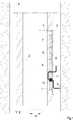
Aus
Von dem Bohrgestänge
Wie aus
Das Absaugen des Rohöls aus der Gesteinsschicht
Die Spektrometerbaugruppe
BezugszeichenlisteLIST OF REFERENCE NUMBERS
- 11
- Spektrometermodulspectrometer module
- 22
- Gestängelinkage
- 33
- Gesteinsschichtrock formation
- 44
- Aussparungrecess
- 55
- Mess- oder PrüfbaugruppeMeasuring or test module
- 66
- Mess- oder PrüfbaugruppeMeasuring or test module
- 77
- Mess- oder PrüfbaugruppeMeasuring or test module
- 88th
- Abdeckungcover
- 99
- Fluidfluid
- 1010
- Saphirfenstersapphire window
- 1111
- Saphirfenstersapphire window
- 1212
- Lichtquellelight source
- 1313
- Strahlungradiation
- 1414
- Spektrometerbaugruppespectrometer assembly
- 1515
- Signalwegpathway
- 1616
- Auswerteeinrichtungevaluation
- 1717
- vom Fluid transmittierte und gestreute Strahlungradiation transmitted and scattered by the fluid
ZITATE ENTHALTEN IN DER BESCHREIBUNG QUOTES INCLUDE IN THE DESCRIPTION
Diese Liste der vom Anmelder aufgeführten Dokumente wurde automatisiert erzeugt und ist ausschließlich zur besseren Information des Lesers aufgenommen. Die Liste ist nicht Bestandteil der deutschen Patent- bzw. Gebrauchsmusteranmeldung. Das DPMA übernimmt keinerlei Haftung für etwaige Fehler oder Auslassungen.This list of the documents listed by the applicant has been generated automatically and is included solely for the better information of the reader. The list is not part of the German patent or utility model application. The DPMA assumes no liability for any errors or omissions.
Zitierte PatentliteraturCited patent literature
- DE 602004012554 T2[0005]DE 602004012554 T2[0005]
- US 2007/0171414 A1[0006]US 2007/0171414 A1[0006]
Claims (14)
Translated fromGermanPriority Applications (1)
| Application Number | Priority Date | Filing Date | Title |
|---|---|---|---|
| DE201110086206DE102011086206A1 (en) | 2011-11-11 | 2011-11-11 | Arrangement for determining spectral characteristics of boring fluid under influence of high temperature and mechanical loads at place of occurrence of fluid, has source for polychromatic electromagnetic radiation source and optical unit |
Applications Claiming Priority (1)
| Application Number | Priority Date | Filing Date | Title |
|---|---|---|---|
| DE201110086206DE102011086206A1 (en) | 2011-11-11 | 2011-11-11 | Arrangement for determining spectral characteristics of boring fluid under influence of high temperature and mechanical loads at place of occurrence of fluid, has source for polychromatic electromagnetic radiation source and optical unit |
Publications (1)
| Publication Number | Publication Date |
|---|---|
| DE102011086206A1true DE102011086206A1 (en) | 2013-05-16 |
Family
ID=48144875
Family Applications (1)
| Application Number | Title | Priority Date | Filing Date |
|---|---|---|---|
| DE201110086206CeasedDE102011086206A1 (en) | 2011-11-11 | 2011-11-11 | Arrangement for determining spectral characteristics of boring fluid under influence of high temperature and mechanical loads at place of occurrence of fluid, has source for polychromatic electromagnetic radiation source and optical unit |
Country Status (1)
| Country | Link |
|---|---|
| DE (1) | DE102011086206A1 (en) |
Citations (8)
| Publication number | Priority date | Publication date | Assignee | Title |
|---|---|---|---|---|
| US5166747A (en)* | 1990-06-01 | 1992-11-24 | Schlumberger Technology Corporation | Apparatus and method for analyzing the composition of formation fluids |
| US20070171413A1 (en)* | 2006-01-26 | 2007-07-26 | Schlumberger Technology Corporation | Method and Apparatus for Downhole Spectral Analysis of Fluids |
| US20070171414A1 (en) | 2006-01-26 | 2007-07-26 | Schlumberger Technology Corporation | Downhole spectral analysis tool |
| US20080030729A1 (en)* | 2006-01-11 | 2008-02-07 | Baker Hughes Incorporated | Method and apparatus for estimating a property of a fluid downhole |
| US20080173445A1 (en)* | 2007-01-24 | 2008-07-24 | Schlumberger Technology Corporation | Methods and Apparatus to Characterize Stock-Tank Oil During Fluid Composition Analysis |
| DE602004012554T2 (en) | 2003-05-02 | 2009-04-16 | Baker-Hughes Inc., Houston | OPTICAL PROCESS AND ANALYZER |
| WO2010068870A2 (en)* | 2008-12-12 | 2010-06-17 | Baker Hughes Incorporated | Apparatus and method for evaluating downhole fluids |
| US20100181472A1 (en)* | 2007-04-09 | 2010-07-22 | Baker Hughes Incorporated | Method and Apparatus to Determine Characteristics of an Oil-Based Mud Downhole |
- 2011
- 2011-11-11DEDE201110086206patent/DE102011086206A1/ennot_activeCeased
Patent Citations (8)
| Publication number | Priority date | Publication date | Assignee | Title |
|---|---|---|---|---|
| US5166747A (en)* | 1990-06-01 | 1992-11-24 | Schlumberger Technology Corporation | Apparatus and method for analyzing the composition of formation fluids |
| DE602004012554T2 (en) | 2003-05-02 | 2009-04-16 | Baker-Hughes Inc., Houston | OPTICAL PROCESS AND ANALYZER |
| US20080030729A1 (en)* | 2006-01-11 | 2008-02-07 | Baker Hughes Incorporated | Method and apparatus for estimating a property of a fluid downhole |
| US20070171413A1 (en)* | 2006-01-26 | 2007-07-26 | Schlumberger Technology Corporation | Method and Apparatus for Downhole Spectral Analysis of Fluids |
| US20070171414A1 (en) | 2006-01-26 | 2007-07-26 | Schlumberger Technology Corporation | Downhole spectral analysis tool |
| US20080173445A1 (en)* | 2007-01-24 | 2008-07-24 | Schlumberger Technology Corporation | Methods and Apparatus to Characterize Stock-Tank Oil During Fluid Composition Analysis |
| US20100181472A1 (en)* | 2007-04-09 | 2010-07-22 | Baker Hughes Incorporated | Method and Apparatus to Determine Characteristics of an Oil-Based Mud Downhole |
| WO2010068870A2 (en)* | 2008-12-12 | 2010-06-17 | Baker Hughes Incorporated | Apparatus and method for evaluating downhole fluids |
Similar Documents
| Publication | Publication Date | Title |
|---|---|---|
| US7826050B2 (en) | System and method for dual path length optical analysis of fluids downhole | |
| DE69601464T2 (en) | ROBUST SPECTROSCOPIC PROBE | |
| DE602004012554T2 (en) | OPTICAL PROCESS AND ANALYZER | |
| DE19856591C2 (en) | Device for the spectroscopic analysis of a fluid medium by means of attenuated reflection | |
| DE60216727T2 (en) | METHOD FOR EVALUATING THE HYDROCARBON POTENTIAL OF SEDIMENTAL BASIN FROM FLUIDE INCLUSIONS | |
| DE102012100794B3 (en) | Apparatus and method for detecting contaminants in a hydraulic system | |
| JP5198287B2 (en) | Downhole spectral analysis tool including inorganic replica diffraction grating | |
| US9651710B2 (en) | Downhole fluid properties analysis device and tools comprising such a device | |
| US20080111064A1 (en) | Downhole measurement of substances in earth formations | |
| DE3418587A1 (en) | METHOD FOR DETERMINING THE PRESENT OF NATURAL HYDROCARBONS WHEN DRILLING A HOLE | |
| DE102013102438B3 (en) | Flow cell for measuring e.g. permittivity of sample fluid in HPLC application, has capillary tubes arranged within protective tube to obviate unwanted mechanical application on side of capillary tubes surrounded along longitudinal direction | |
| WO2009039920A1 (en) | Arrangement, method, and sensor for detecting fluid parameters | |
| DE112015006212T5 (en) | Optical calculation based on a spectrally programmable memristor | |
| EP1511917B1 (en) | Method and apparatus for a high resolution downhole spectrometer | |
| DE102019131698A1 (en) | System and method for the analysis of liquids | |
| EP1530714A1 (en) | X-ray fluorescence analysis using a waveguide connected to the source and to the detector | |
| DE102011086206A1 (en) | Arrangement for determining spectral characteristics of boring fluid under influence of high temperature and mechanical loads at place of occurrence of fluid, has source for polychromatic electromagnetic radiation source and optical unit | |
| DE102014014414B4 (en) | Method and arrangement for hydrogen sensing | |
| DE4425462A1 (en) | Spectrophotometer cell | |
| DE102011016059B4 (en) | Method for correcting Raman spectroscopic data in a multiphase system | |
| DE102005036146A1 (en) | Gas burner flames testing arrangement for use in gas supply system, has camera including spectral sensor with spectral gauge head arranged in housing, where images and spectrum of flames of gas burner are taken up simultaneously | |
| Fujisawa et al. | Development and applications of ruggedized VIS/NIR spectrometer system for oilfield wellbores | |
| EP3770585B1 (en) | Device and method for detecting a concentration of a substance in a fluid | |
| DE112015006227T5 (en) | Mobile assembly for simultaneous recognition of analytical signals and compensation signals in otpic computing | |
| EP1845362B1 (en) | Spectroscopy apparatus |
Legal Events
| Date | Code | Title | Description |
|---|---|---|---|
| R163 | Identified publications notified | ||
| R081 | Change of applicant/patentee | Owner name:CARL ZEISS SPECTROSCOPY GMBH, DE Free format text:FORMER OWNERS: CARL ZEISS AG, 73447 OBERKOCHEN, DE; CARL ZEISS JENA GMBH, 07745 JENA, DE; CARL ZEISS MICROLMAGING GMBH, 07745 JENA, DE | |
| R082 | Change of representative | Representative=s name:PATENTANWAELTE GEYER, FEHNERS & PARTNER MBB, DE Representative=s name:GEYER, FEHNERS & PARTNER (G.B.R.), DE | |
| R079 | Amendment of ipc main class | Free format text:PREVIOUS MAIN CLASS: G01N0021350000 Ipc:G01N0021357700 | |
| R079 | Amendment of ipc main class | Free format text:PREVIOUS MAIN CLASS: G01N0021350000 Ipc:G01N0021357700 Effective date:20131216 | |
| R081 | Change of applicant/patentee | Owner name:CARL ZEISS SPECTROSCOPY GMBH, DE Free format text:FORMER OWNERS: CARL ZEISS AG, 73447 OBERKOCHEN, DE; CARL ZEISS JENA GMBH, 07745 JENA, DE; CARL ZEISS MICROSCOPY GMBH, 07745 JENA, DE | |
| R082 | Change of representative | Representative=s name:GLEIM PETRI OEHMKE PATENT- UND RECHTSANWALTSPA, DE Representative=s name:PATENTANWAELTE GEYER, FEHNERS & PARTNER MBB, DE | |
| R012 | Request for examination validly filed | ||
| R082 | Change of representative | Representative=s name:GLEIM PETRI OEHMKE PATENT- UND RECHTSANWALTSPA, DE | |
| R016 | Response to examination communication | ||
| R002 | Refusal decision in examination/registration proceedings | ||
| R003 | Refusal decision now final |