DE102011084910A1 - Method and device for feeding electrical current into an electrical network - Google Patents
Method and device for feeding electrical current into an electrical networkDownload PDFInfo
- Publication number
- DE102011084910A1 DE102011084910A1DE102011084910ADE102011084910ADE102011084910A1DE 102011084910 A1DE102011084910 A1DE 102011084910A1DE 102011084910 ADE102011084910 ADE 102011084910ADE 102011084910 ADE102011084910 ADE 102011084910ADE 102011084910 A1DE102011084910 A1DE 102011084910A1
- Authority
- DE
- Germany
- Prior art keywords
- voltage
- network
- current
- phase
- phase angle
- Prior art date
- Legal status (The legal status is an assumption and is not a legal conclusion. Google has not performed a legal analysis and makes no representation as to the accuracy of the status listed.)
- Ceased
Links
- 238000000034methodMethods0.000titleclaimsabstractdescription65
- 238000004364calculation methodMethods0.000claimsabstractdescription70
- 230000001131transforming effectEffects0.000claimsabstract2
- 230000009466transformationEffects0.000claimsdescription41
- 238000005259measurementMethods0.000claimsdescription11
- 238000001514detection methodMethods0.000claimsdescription7
- 238000009434installationMethods0.000claims1
- 230000001360synchronised effectEffects0.000description10
- 238000003775Density Functional TheoryMethods0.000description9
- 230000008859changeEffects0.000description7
- 238000000354decomposition reactionMethods0.000description7
- 230000000694effectsEffects0.000description6
- 230000010354integrationEffects0.000description3
- 230000000737periodic effectEffects0.000description3
- 230000008569processEffects0.000description3
- 238000006243chemical reactionMethods0.000description2
- BUHVIAUBTBOHAG-FOYDDCNASA-N(2r,3r,4s,5r)-2-[6-[[2-(3,5-dimethoxyphenyl)-2-(2-methylphenyl)ethyl]amino]purin-9-yl]-5-(hydroxymethyl)oxolane-3,4-diolChemical compoundCOC1=CC(OC)=CC(C(CNC=2C=3N=CN(C=3N=CN=2)[C@H]2[C@@H]([C@H](O)[C@@H](CO)O2)O)C=2C(=CC=CC=2)C)=C1BUHVIAUBTBOHAG-FOYDDCNASA-N0.000description1
- 238000009825accumulationMethods0.000description1
- 230000009471actionEffects0.000description1
- 230000015572biosynthetic processEffects0.000description1
- 239000003990capacitorSubstances0.000description1
- 230000008878couplingEffects0.000description1
- 238000010168coupling processMethods0.000description1
- 238000005859coupling reactionMethods0.000description1
- 230000001419dependent effectEffects0.000description1
- 238000013461designMethods0.000description1
- 238000010586diagramMethods0.000description1
- 230000005611electricityEffects0.000description1
- 238000011156evaluationMethods0.000description1
- 230000006872improvementEffects0.000description1
- 230000007935neutral effectEffects0.000description1
- 230000010363phase shiftEffects0.000description1
- 238000002360preparation methodMethods0.000description1
- 230000009467reductionEffects0.000description1
- 230000002441reversible effectEffects0.000description1
- 238000005070samplingMethods0.000description1
- 239000004065semiconductorSubstances0.000description1
- 230000000087stabilizing effectEffects0.000description1
- 238000012546transferMethods0.000description1
- 230000001960triggered effectEffects0.000description1
Images


Classifications
- H—ELECTRICITY
- H02—GENERATION; CONVERSION OR DISTRIBUTION OF ELECTRIC POWER
- H02J—CIRCUIT ARRANGEMENTS OR SYSTEMS FOR SUPPLYING OR DISTRIBUTING ELECTRIC POWER; SYSTEMS FOR STORING ELECTRIC ENERGY
- H02J3/00—Circuit arrangements for AC mains or AC distribution networks
- F—MECHANICAL ENGINEERING; LIGHTING; HEATING; WEAPONS; BLASTING
- F03—MACHINES OR ENGINES FOR LIQUIDS; WIND, SPRING, OR WEIGHT MOTORS; PRODUCING MECHANICAL POWER OR A REACTIVE PROPULSIVE THRUST, NOT OTHERWISE PROVIDED FOR
- F03D—WIND MOTORS
- F03D7/00—Controlling wind motors
- F03D7/02—Controlling wind motors the wind motors having rotation axis substantially parallel to the air flow entering the rotor
- F03D7/028—Controlling wind motors the wind motors having rotation axis substantially parallel to the air flow entering the rotor controlling wind motor output power
- F03D7/0284—Controlling wind motors the wind motors having rotation axis substantially parallel to the air flow entering the rotor controlling wind motor output power in relation to the state of the electric grid
- H—ELECTRICITY
- H02—GENERATION; CONVERSION OR DISTRIBUTION OF ELECTRIC POWER
- H02J—CIRCUIT ARRANGEMENTS OR SYSTEMS FOR SUPPLYING OR DISTRIBUTING ELECTRIC POWER; SYSTEMS FOR STORING ELECTRIC ENERGY
- H02J3/00—Circuit arrangements for AC mains or AC distribution networks
- H02J3/26—Arrangements for eliminating or reducing asymmetry in polyphase networks
- H—ELECTRICITY
- H02—GENERATION; CONVERSION OR DISTRIBUTION OF ELECTRIC POWER
- H02J—CIRCUIT ARRANGEMENTS OR SYSTEMS FOR SUPPLYING OR DISTRIBUTING ELECTRIC POWER; SYSTEMS FOR STORING ELECTRIC ENERGY
- H02J3/00—Circuit arrangements for AC mains or AC distribution networks
- H02J3/38—Arrangements for parallely feeding a single network by two or more generators, converters or transformers
- H02J3/381—Dispersed generators
- H—ELECTRICITY
- H02—GENERATION; CONVERSION OR DISTRIBUTION OF ELECTRIC POWER
- H02J—CIRCUIT ARRANGEMENTS OR SYSTEMS FOR SUPPLYING OR DISTRIBUTING ELECTRIC POWER; SYSTEMS FOR STORING ELECTRIC ENERGY
- H02J3/00—Circuit arrangements for AC mains or AC distribution networks
- H02J3/38—Arrangements for parallely feeding a single network by two or more generators, converters or transformers
- H02J3/40—Synchronising a generator for connection to a network or to another generator
- H02J3/44—Synchronising a generator for connection to a network or to another generator with means for ensuring correct phase sequence
- H—ELECTRICITY
- H02—GENERATION; CONVERSION OR DISTRIBUTION OF ELECTRIC POWER
- H02J—CIRCUIT ARRANGEMENTS OR SYSTEMS FOR SUPPLYING OR DISTRIBUTING ELECTRIC POWER; SYSTEMS FOR STORING ELECTRIC ENERGY
- H02J3/00—Circuit arrangements for AC mains or AC distribution networks
- H02J3/38—Arrangements for parallely feeding a single network by two or more generators, converters or transformers
- H02J3/46—Controlling of the sharing of output between the generators, converters, or transformers
- H02J3/48—Controlling the sharing of the in-phase component
- H—ELECTRICITY
- H02—GENERATION; CONVERSION OR DISTRIBUTION OF ELECTRIC POWER
- H02J—CIRCUIT ARRANGEMENTS OR SYSTEMS FOR SUPPLYING OR DISTRIBUTING ELECTRIC POWER; SYSTEMS FOR STORING ELECTRIC ENERGY
- H02J3/00—Circuit arrangements for AC mains or AC distribution networks
- H02J3/38—Arrangements for parallely feeding a single network by two or more generators, converters or transformers
- H02J3/46—Controlling of the sharing of output between the generators, converters, or transformers
- H02J3/50—Controlling the sharing of the out-of-phase component
- H—ELECTRICITY
- H02—GENERATION; CONVERSION OR DISTRIBUTION OF ELECTRIC POWER
- H02M—APPARATUS FOR CONVERSION BETWEEN AC AND AC, BETWEEN AC AND DC, OR BETWEEN DC AND DC, AND FOR USE WITH MAINS OR SIMILAR POWER SUPPLY SYSTEMS; CONVERSION OF DC OR AC INPUT POWER INTO SURGE OUTPUT POWER; CONTROL OR REGULATION THEREOF
- H02M5/00—Conversion of AC power input into AC power output, e.g. for change of voltage, for change of frequency, for change of number of phases
- H02M5/40—Conversion of AC power input into AC power output, e.g. for change of voltage, for change of frequency, for change of number of phases with intermediate conversion into DC
- H—ELECTRICITY
- H02—GENERATION; CONVERSION OR DISTRIBUTION OF ELECTRIC POWER
- H02J—CIRCUIT ARRANGEMENTS OR SYSTEMS FOR SUPPLYING OR DISTRIBUTING ELECTRIC POWER; SYSTEMS FOR STORING ELECTRIC ENERGY
- H02J2300/00—Systems for supplying or distributing electric power characterised by decentralized, dispersed, or local generation
- H02J2300/20—The dispersed energy generation being of renewable origin
- H02J2300/28—The renewable source being wind energy
- Y—GENERAL TAGGING OF NEW TECHNOLOGICAL DEVELOPMENTS; GENERAL TAGGING OF CROSS-SECTIONAL TECHNOLOGIES SPANNING OVER SEVERAL SECTIONS OF THE IPC; TECHNICAL SUBJECTS COVERED BY FORMER USPC CROSS-REFERENCE ART COLLECTIONS [XRACs] AND DIGESTS
- Y02—TECHNOLOGIES OR APPLICATIONS FOR MITIGATION OR ADAPTATION AGAINST CLIMATE CHANGE
- Y02E—REDUCTION OF GREENHOUSE GAS [GHG] EMISSIONS, RELATED TO ENERGY GENERATION, TRANSMISSION OR DISTRIBUTION
- Y02E10/00—Energy generation through renewable energy sources
- Y02E10/70—Wind energy
- Y02E10/72—Wind turbines with rotation axis in wind direction
- Y—GENERAL TAGGING OF NEW TECHNOLOGICAL DEVELOPMENTS; GENERAL TAGGING OF CROSS-SECTIONAL TECHNOLOGIES SPANNING OVER SEVERAL SECTIONS OF THE IPC; TECHNICAL SUBJECTS COVERED BY FORMER USPC CROSS-REFERENCE ART COLLECTIONS [XRACs] AND DIGESTS
- Y02—TECHNOLOGIES OR APPLICATIONS FOR MITIGATION OR ADAPTATION AGAINST CLIMATE CHANGE
- Y02E—REDUCTION OF GREENHOUSE GAS [GHG] EMISSIONS, RELATED TO ENERGY GENERATION, TRANSMISSION OR DISTRIBUTION
- Y02E10/00—Energy generation through renewable energy sources
- Y02E10/70—Wind energy
- Y02E10/76—Power conversion electric or electronic aspects
- Y—GENERAL TAGGING OF NEW TECHNOLOGICAL DEVELOPMENTS; GENERAL TAGGING OF CROSS-SECTIONAL TECHNOLOGIES SPANNING OVER SEVERAL SECTIONS OF THE IPC; TECHNICAL SUBJECTS COVERED BY FORMER USPC CROSS-REFERENCE ART COLLECTIONS [XRACs] AND DIGESTS
- Y02—TECHNOLOGIES OR APPLICATIONS FOR MITIGATION OR ADAPTATION AGAINST CLIMATE CHANGE
- Y02E—REDUCTION OF GREENHOUSE GAS [GHG] EMISSIONS, RELATED TO ENERGY GENERATION, TRANSMISSION OR DISTRIBUTION
- Y02E40/00—Technologies for an efficient electrical power generation, transmission or distribution
- Y02E40/50—Arrangements for eliminating or reducing asymmetry in polyphase networks
Landscapes
- Engineering & Computer Science (AREA)
- Power Engineering (AREA)
- Chemical & Material Sciences (AREA)
- Sustainable Energy (AREA)
- Life Sciences & Earth Sciences (AREA)
- Combustion & Propulsion (AREA)
- Mechanical Engineering (AREA)
- General Engineering & Computer Science (AREA)
- Sustainable Development (AREA)
- Supply And Distribution Of Alternating Current (AREA)
- Remote Monitoring And Control Of Power-Distribution Networks (AREA)
- Inverter Devices (AREA)
- Wind Motors (AREA)
- Direct Current Feeding And Distribution (AREA)
- Measurement Of Current Or Voltage (AREA)
- Ac-Ac Conversion (AREA)
Abstract
Translated fromGermanDescription
Translated fromGermanDie vorliegende Erfindung betrifft ein Verfahren und eine Vorrichtung zum Einspeisen elektrischen Stroms in ein elektrisches Dreiphasennetz. Außerdem betrifft die vorliegende Erfindung eine Windenergieanlage, die zum Einspeisen elektrischen Stroms in ein dreiphasiges Netz vorbereitet ist.The present invention relates to a method and apparatus for feeding electrical power into a three-phase electrical network. Moreover, the present invention relates to a wind turbine that is prepared for feeding electric power into a three-phase network.
Verfahren und Vorrichtungen zum Einspeisen elektrischen Stroms in ein elektrisches dreiphasiges Netz wie beispielsweise das europäische Verbundnetz bzw. in einen Teil davon sind allgemein bekannt. Großkraftwerke verwenden hierfür einen Synchrongenerator, der unmittelbar an das elektrische Netz angeschlossen ist. Der Synchrongenerator wird hierfür mit einer entsprechenden Drehzahl betrieben, die genau auf die Frequenz des elektrischen Netzes abgestimmt ist. je nach Bauform des Synchrongenerators beträgt die Drehzahl z. B. 1500 Umdrehungen pro Minute bei einem vierpoligen Synchrongenerator, der an ein Netz mit einer Frequenz von 50 Hz angeschlossen ist. Treten Störungen im Netz auf, wie beispielsweise eine unsymmetrische Belastung des Netzes bei der beispielsweise eine der drei Netzphasen stärker belastet wird, hat dies unmittelbar Auswirkung auf den vom Synchrongenerator gelieferten Strom. Das physikalisch bedingte Verhalten des Synchrongenerators kann hierbei zumindest teilweise wieder zu einer Symmetrierung des Netzes beitragen. Die Art und Weise eines solchen Beitrages des Synchrongenerators kann aber aufgrund der starren Kopplung mit dem Netz in Grunde nicht beeinflusst werden.Methods and devices for feeding electrical current into a three-phase electrical network such as the European interconnected network or in a part thereof are well known. Large power plants use a synchronous generator, which is directly connected to the electrical grid. The synchronous generator is operated for this purpose with a corresponding speed, which is tuned exactly to the frequency of the electrical network. depending on the design of the synchronous generator, the speed is z. B. 1500 revolutions per minute with a four-pole synchronous generator, which is connected to a network with a frequency of 50 Hz. If disturbances occur in the network, such as, for example, an unbalanced load on the network in which, for example, one of the three network phases is more heavily loaded, this has a direct effect on the current supplied by the synchronous generator. The physically related behavior of the synchronous generator can in this case at least partially contribute to a symmetrization of the network. However, the manner of such a contribution of the synchronous generator can not be influenced due to the rigid coupling with the network basically.
Windenergieanlagen sind noch in den 90iger Jahren im wesentlichen in dem Sinne passiv an das Netz angeschlossen gewesen, dass sie soviel Energie in das Netz einspeisen, wie aufgrund der vorherrschenden Windbedingungen jeweils aktuell möglich ist. Ende der 90iger Jahre wurde erstmals erkannt, dass auch Windenergieanlagen zur elektrischen Stützung des Netzes einen Beitrag leisten können. So beschreibt beispielsweise die deutsche Patentanmeldung
Windenergieanlagen gewinnen zunehmend an Bedeutung. Auch hinsichtlich einer Netzstützung gewinnen sie zunehmend an Bedeutung. Die oben beschriebenen Maßnahmen zur Netzstützung – die man wohl als Pionierschritte bezeichnen kann – sind dabei aber insoweit noch verbesserbar, dass auch Netzunsymmetrien berücksichtigt werden.Wind turbines are becoming increasingly important. In terms of network support, they are also becoming increasingly important. The above-described measures for network support - which can probably be described as pioneering steps - are, however, to that extent still be improved, that also Netzunsymmetrien be considered.
Die Berücksichtigung von Netzunsymmetrien weist dabei einige Probleme auf. Zunächst ist es problematisch, Netzunsymmetrien schnell und genau zu erfassen. Weiterhin stellt sich das Problem im Falle einer Erfassung von Unsymmetrien, diese gezielt auszugleichen, was mit einem stark gekoppelten Synchrongenerator nicht oder nur bedingt möglich ist. Gleiche Probleme treten auf bei Systemen, die keinen Synchrongenerator verwenden, sondern einen solchen dem Verhalten nach nachbilden.The consideration of network imbalances has some problems. First, it is problematic to detect network imbalances quickly and accurately. Furthermore, the problem arises in the case of detection of asymmetries to balance these targeted, which is not or only partially possible with a strongly coupled synchronous generator. Similar problems occur in systems that do not use a synchronous generator, but emulate such a behavior.
Der vorliegenden Erfindung liegt somit die Aufgabe zugrunde, wenigstens eins der oben genannten Probleme zu lösen oder zu verringern. Insbesondere soll eine Lösung geschaffen werden, bei der gezielt unsymmetrisch in das Netz eingespeist werden soll, um im Netz vorhandenen Unsymmetrien zu begegnen. Zumindest soll eine alternative Lösung geschaffen werden.The present invention is therefore based on the object to solve or reduce at least one of the above problems. In particular, a solution is to be created in which targeted unbalanced is to be fed into the network to counteract network imbalances existing. At least an alternative solution should be created.
Erfindungsgemäß wird ein Verfahren nach Anspruch 1 vorgeschlagen.According to the invention, a method according to
Entsprechend wird ein Verfahren vorgeschlagen zum Einspeisen elektrischen Stroms in ein elektrisches, dreiphasiges Netz mit einer ersten, zweiten und dritten Phase mit einer ersten, zweiten und dritten Spannung mit einer Netzfrequenz. Das Verfahren geht somit von einem dreiphasigen System mit einer Frequenz, nämlich der Netzfrequenz, aus, bei dem jede Phase eine eigene Spannung aufweist, die sich von den Spannungen der anderen Phasen unterscheiden kann. Das Verfahren berücksichtigt somit insbesondere auch ein unsymmetrisches Dreiphasensystem.Accordingly, a method is proposed for feeding electrical current into an electrical, three-phase network having a first, second and third phase with a first, second and third voltage at a mains frequency. The method is thus based on a three-phase system with a frequency, namely the mains frequency, in which each phase has its own voltage, which may differ from the voltages of the other phases. The method thus takes into account, in particular, an asymmetrical three-phase system.
Gemäß einem Schritt wird die erste, zweite und dritte Spannung gemessen und die Spannungen werden in ein Spannungs-Mitsystem und ein Spannungs-Gegensystem nach der Methode der symmetrischen Komponenten transformiert. Das dreiphasige Spannungssystem kann somit trotz Berücksichtigung von Unsymmetrien auf einfache und allgemeine Weise beschrieben werden. Es wird davon ausgegangen, dass nur drei Leitungen, die üblicherweise als L1, L2 und L3 bezeichnet werden, Strom führen und somit ein Nullsystem nicht vorliegt bzw. zur Beschreibung nicht benötigt wird, sondern eine Beschreibung durch Spannungs-Mitsystem und Spannungs-Gegensystem ausreicht. According to one step, the first, second and third voltages are measured and the voltages are transformed into a voltage system and a voltage negative system according to the symmetrical component method. The three-phase voltage system can thus be described in a simple and general way, despite consideration of asymmetries. It is assumed that only three lines, which are usually referred to as L1, L2 and L3, carry power and thus a zero system is not present or is not needed for the description, but a description by voltage co-system and voltage negative sequence sufficient.
Es erfolgt weiterhin ein Berechnen eines ersten, zweiten und dritten Sollstroms zum Einspeisen in die erste, zweite bzw. dritte Phase des Netzes. Es wird darauf hingewiesen, dass das Vorsehen und Einspeisen eines solchen ersten, zweiten und dritten Stromes – die drei Ströme können auch zusammen als dreiphasiger Strom bezeichnet werden – grundsätzlich und wesentlich von dem Generieren eines dreiphasigen Stroms zum Ansteuern eines Gerätes wie eines Elektromotors unterscheidet. So fehlt es beim Einspeisen eines Stroms in ein elektrisches Netz üblicherweise an einer unmittelbaren und insbesondere deterministischen Reaktion auf die Einspeisung, wie es im Falle eines gut bekannten Verbrauchers der Fall wäre. Zwar reagiert auch das elektrische Netz auf den jeweils eingespeisten Strom, gleichwohl ist eine solche Reaktion mit der eines unmittelbar vorhandenen und klar identifizierbaren Verbrauchers wie beispielsweise eines elektrischen Motors, nicht vergleichbar.Furthermore, a calculation of a first, second and third setpoint current for feeding into the first, second or third phase of the network takes place. It should be noted that the provision and feeding of such a first, second and third current - the three currents may also be referred to together as a three-phase current - fundamentally and substantially different from the generation of a three-phase current for driving a device such as an electric motor. Thus, when feeding a current into an electrical network, it is usually lacking an immediate and in particular deterministic reaction to the feed, as would be the case in the case of a well-known consumer. Although the electrical network also responds to the current fed in each time, such a reaction is not comparable to that of an immediately available and clearly identifiable consumer such as, for example, an electric motor.
Die Berechnung des ersten, zweiten und dritten Sollstroms erfolgt in Abhängigkeit wenigstens eines Wertes des Spannungs-Mitsystems und/oder des Spannungs-Gegensystems. Somit wird zunächst einmal vorgeschlagen, beim Einspeisen in das dreiphasige Netz Unsymmetrien des Netzes zu berücksichtigen und dementsprechend die drei einzuspeisenden Ströme zu berechnen. Für die Berücksichtigung der Netzunsymmetrien wird somit die Berechnung der Sollströme in Abhängigkeit des Spannungs-Mitsystems bzw. des Spannungs-Gegensystems vorgeschlagen. Hierdurch kann gezielt auf entsprechende Unsymmetrien im Netz reagiert werden.The calculation of the first, second and third desired current takes place as a function of at least one value of the voltage co-system and / or the voltage negative sequence system. Thus, it is first proposed, when feeding into the three-phase network to take into account asymmetries of the network and accordingly to calculate the three currents to be fed. For the consideration of the network imbalances, the calculation of the desired currents as a function of the voltage co-system or the voltage negative sequence system is thus proposed. As a result, it is possible to respond specifically to corresponding asymmetries in the network.
Im Gegensatz zu herkömmlichen Großkraftwerken, die über einen Star mit dem Netz gekoppelten Synchrongenerator die Netzeinspeisung vornehmen, wird nun eine gezielte Berechnung der Sollströme in Abhängigkeit der Unsymmetrie bzw. unter Berücksichtigung derselben vorgeschlagen.In contrast to conventional large-scale power plants, which feed the grid via a star coupled to the grid synchronous generator, a targeted calculation of the desired currents depending on the imbalance or taking into account the same is now proposed.
Es erfolgt also eine Berücksichtigung etwaiger Unsymmetrien der Netzspannung, was Konsequenzen auf die Berechnung des einzuspeisenden Stromes hat. Das Mitsystem und/oder Gegensystem der Netzspannung wirkt sich somit aus auf die einzuspeisenden Ströme aus.Thus, consideration is given to any imbalances in the mains voltage, which has consequences for the calculation of the current to be injected. The positive sequence and / or negative sequence of the mains voltage thus affects the currents to be injected.
Gemäß einer Ausführungsform wird vorgeschlagen, dass mittels eines Frequenzwechselrichters elektrische Ströme entsprechend dem ersten, zweiten und dritten Sollstrom zum Einspeisen in das dreiphasige Spannungsnetz erzeugt und eingespeist werden. Es erfolgt somit im Grunde unmittelbar eine Erzeugung der Ströme durch den Wechselrichter, wie dies beispielsweise durch eine Pulsweitenmodulation vorgenommen werden kann. Hierfür kann die einzuspeisende Energie in einem Gleichspannungszwischenkreis bereitgestellt werden, von dem aus die Pulsweitenmodulation durchgeführt wird, um aus dem Gleichspannungssignal des Gleichspannungszwischenkreises einen oszillierenden, insbesondere sinusförmigen Strom jeweils zu generieren.According to one embodiment, it is proposed that electrical currents corresponding to the first, second and third setpoint currents are generated and fed in for feeding into the three-phase voltage network by means of a frequency inverter. Thus, there is basically a direct generation of the currents through the inverter, as can be done for example by a pulse width modulation. For this purpose, the energy to be supplied can be provided in a DC voltage intermediate circuit, from which the pulse width modulation is carried out in order to generate an oscillating, in particular sinusoidal, current from the DC voltage signal of the DC intermediate circuit.
Vorzugsweise wird die elektrische Energie hierfür, insbesondere für den beispielhaft genannten Gleichspannungszwischenkreis, durch eine Windenergieanlage bereitgestellt, die erzeugte Wechselspannungsenergie mittels eines Gleichrichters in Energie mit einer Gleichspannung wandelt. Hierdurch soll insbesondere ermöglicht werden, Windenergieanlagen oder Windparks mit mehreren Windenergieanlagen zum Stabilisieren des Netzes und insbesondere zum Stabilisieren eines unsymmetrischen Netzes einzusetzen. Zumindest wird vorzugsweise die elektrische Energie von Windenergieanlagen so ins Netz eingespeist, dass eine etwaige vorliegende Unsymmetrie nicht verstärkt wird, der Netzzustand also nicht verschlechtert wird.Preferably, the electrical energy for this purpose, in particular for the DC voltage intermediate circuit mentioned by way of example, is provided by a wind power plant, which converts the generated AC voltage energy into a DC voltage by means of a rectifier. This is to be made possible in particular to use wind turbines or wind farms with multiple wind turbines to stabilize the network and in particular to stabilize a single-ended network. At least the electrical energy of wind turbines is preferably fed into the grid so that any unbalance present is not amplified, so the network condition is not deteriorated.
Gemäß einer Ausführungsform ist das Verfahren dadurch gekennzeichnet, dass zum Berechnen der Sollströme ein Berechnungsphasenwinkel zugrunde gelegt wird und der Berechnungsphasenwinkel abhängig von einer Detektion eines Netzfehlers bestimmt wird, insbesondere unter Verwendung eines Bestimmungsfilters bzw. Filterblocks. Dabei wird der Berechnungsphasenwinkel aus einem erfassten Phasenwinkel einer der Netzspannungen bestimmt, wenn kein Netzfehler detektiert wurde. Andernfalls, wenn ein Netzfehler detektiert wurde oder anzunehmen ist, wird vorgeschlagen, dass der Berechnungsphasenwinkel anderweitig, insbesondere aus einem Phasenwinkel des Spannungs-Mitsystems bestimmt wird und/oder dass der Berechnungsphasenwinkel unter Verwendung einer vorgegebenen Netzfrequenz bestimmt wird.According to one embodiment, the method is characterized in that a calculation phase angle is used for calculating the desired currents and the calculation phase angle is determined as a function of a detection of a network error, in particular using a determination filter or filter block. In this case, the calculation phase angle is determined from a detected phase angle of one of the mains voltages if no network error was detected. Otherwise, if a network error has been detected or is to be assumed, it is proposed that the calculation phase angle be determined otherwise, in particular from a phase angle of the voltage co-system and / or that the calculation phase angle is determined using a predetermined network frequency.
Demnach legt die Bestimmung bzw. Berechnung der Sollströme nicht unmittelbar einen bei der Messung der dreiphasigen Spannung erfassten Phasenwinkel zugrunde, sondern es wird ein spezieller Phasenwinkel berechnet, der der Berechnung der Sollströme zugrunde gelegt wird und der deswegen als Berechnungsphasenwinkel bezeichnet wird. Der Berechnungsphasenwinkel sollte sich beispielsweise durch eine hohe Genauigkeit und/oder geringes Rauschen auszeichnen. Der Berechnungsphasenwinkel kann beispielsweise über einen Bestimmungsfilter bzw. Filterblock bestimmt werden. Dieser Bestimmungsfilter bzw. Filterblock kann beispielsweise als Zustandsbeobachter ausgebildet sein. Eine Berechnung des Phasenwinkels kann beispielsweise so erfolgen, wie in der Offenlegungsschrift
Der Berechnungsphasenwinkel wird vorzugsweise aus einem Phasenwinkel des Spannungs-Mitsystems bestimmt, wenn ein Netzfehler detektiert wurde. Hier wird insbesondere auf diese andere Quelle zur Bestimmung umgeschaltet, was auch als Softwarelösung ausgeführt sein kann. Hierfür wird die Verwendung des Phasenwinkels des Spannungs-Mitsystems vorgeschlagen. Zumindest zu Beginn eines auftretenden Netzfehlers kann es möglich sein, dass der Phasenwinkel des Spannungs-Mitsystems einen verlässlichen Wert oder zumindest ausreichend verlässlichen Wert für den Phasenwinkel liefert. Häufig geht ein Netzfehler auch mit Problemen der Spannungsmessung einher. Dies kann beispielsweise darin begründet sein, dass die Spannung nicht, schlecht oder teilweise nicht oder schlecht gemessen werden kann. Ein anderes Problem kann darin bestehen, dass eine Messung bzw. Erfassung der Spannung des dreiphasigen Systems von Bedingungen ausgeht, die möglicherweise im Netzfehlerfall nicht mehr vorliegen.The calculation phase angle is preferably determined from a phase angle of the voltage co-system when a network error has been detected. Here is switched in particular to this other source for determination, which can also be implemented as a software solution. For this purpose, the use of the phase angle of the voltage co-system is proposed. At least at the beginning of an occurring network fault, it may be possible for the phase angle of the voltage co-system to provide a reliable value or at least sufficiently reliable value for the phase angle. Often, a network failure is also associated with problems of voltage measurement. This may be due, for example, to the fact that the tension can not be measured, badly or in part can not be or badly measured. Another problem may be that a measurement or detection of the voltage of the three-phase system of conditions emanating from conditions that may no longer exist in the event of network failure.
Alternativ oder zusätzlich wird vorgeschlagen, im Falle eines Netzfehlers zur Berechnung des Berechnungsphasenwinkels eine vorgegebene Netzfrequenz zu verwenden. Im einfachsten Fall wird eine feste Frequenz wie beispielsweise die Nennfrequenz, also z. B. exakt 50 Hz oder exakt 60 Hz, konstant vorgegeben und der Phasenwinkel daraus, im einfachsten Fall über Integration bestimmt. Vorzugsweise wird die Verwendung einer vorgegebenen Frequenz mit der Verwendung eines Phasenwinkels aus dem Spannungs-Mitsystem kombiniert. Eine solche Kombination kann so erfolgen, dass die Bestimmung des Spannungs-Mitsystems und dabei auch des Spannungs-Gegensystems selbst eine vorgegebene Frequenz verwendet, wobei entsprechend auch der Phasenwinkel des Spannungs-Mitsystems bestimmt wird und somit unter Verwendung der vorgegebenen Frequenz bestimmt wird.Alternatively or additionally, it is proposed to use a predetermined network frequency in the case of a network error for calculating the calculation phase angle. In the simplest case, a fixed frequency such as the nominal frequency, ie z. B. exactly 50 Hz or exactly 60 Hz, given constant and the phase angle thereof, in the simplest case determined by integration. Preferably, the use of a given frequency is combined with the use of a phase angle from the voltage co-system. Such a combination can be carried out such that the determination of the voltage co-system and thereby also the voltage negative sequence system itself uses a predetermined frequency, and accordingly the phase angle of the voltage Mitsystems is determined and thus determined using the predetermined frequency.
Weiter bevorzugt wird vorgeschlagen, dass für die Berechnung der Sollströme, insbesondere wenn ein Netzfehler detektiert wird, auf das Spannungs-Mitsystem, insbesondere auf den Phasenwinkel des Spannungs-Mitsystems referenziert wird. Ein wichtiger Aspekt beim Einspeisen elektrischen Stroms in ein Wechselspannungsnetz, insbesondere in ein dreiphasiges Wechselspannungsnetz, ist der Phasenwinkel, mit dem in das Netz eingespeist wird. Die Vorgabe eines Phasenwinkels des dreiphasigen Sollstroms bzw. eines Phasenwinkels für jeden Sollstrom setzt eine möglichst genaue Kenntnis des Netzphasenwinkels voraus bzw. eine möglichst genaue Kenntnis ist wünschenswert. Problematisch bei der Einspeisung des dreiphasigen Stroms ist daher eine ungenaue Kenntnis des Netzphasenwinkels, die beispielsweise dann auftreten kann, wenn ein Netzfehler vorliegt. Ebenso ist – gegebenenfalls mit dem zusätzlichen Problem einer ungenauen Messung – ein unsymmetrisches Netz problematisch, weil sich bereits Probleme bei der Festlegung eines geeigneten Phasenwinkels für einen solchen unsymmetrischen Fall ergeben können.More preferably, it is proposed that, for the calculation of the desired currents, in particular when a network error is detected, reference is made to the voltage co-system, in particular to the phase angle of the voltage co-system. An important aspect when feeding electric current into an AC voltage network, in particular into a three-phase AC voltage network, is the phase angle with which the network is fed. The specification of a phase angle of the three-phase desired current or of a phase angle for each desired current presupposes the most accurate knowledge of the network phase angle or the most accurate possible knowledge is desirable. The problem with feeding the three-phase current is therefore an inaccurate knowledge of the network phase angle, which can occur, for example, when there is a network error. Likewise, possibly with the added problem of inaccurate measurement, an unbalanced network is problematic because there may already be problems in establishing a suitable phase angle for such an asymmetrical case.
Durch die Referenzierung auf den Phasenwinkel der Spannungs-Mitsystemkomponente wird hier eine Lösung vorgeschlagen, die diese Probleme adressiert. Aus der Bestimmung der Mitsystemkomponente, die das Bestimmen des Phasenwinkels der Mitsystemkomponente beinhaltet, ergibt sich ein verhältnismäßig stabiler Wert, der gleichzeitig etwaige Unsymmetrien des dreiphasigen Netzes berücksichtigt. Die Referenzierung der Bestimmung der Sollströme hierauf, also das Zugrundelegen des Phasenwinkels des Mitsystems bzw. eines hieraus berechneten Phasenwinkels der Spannung, ermöglicht somit eine geeignete Sollstromvorgabe auch für nicht ideale Bedingungen im dreiphasigen Netz.By referencing to the phase angle of the voltage Mitsystemkomponente a solution is proposed here, which addresses these problems. From the determination of the Mitsystemkomponente, which includes determining the phase angle of the Mitsystemkomponente, results in a relatively stable value, which also takes into account any asymmetries of the three-phase network. The referencing of the determination of the desired currents thereon, that is to say the basis of the phase angle of the positive sequence or of a phase angle of the voltage calculated therefrom, thus makes possible a suitable setpoint current specification even for non-ideal conditions in the three-phase network.
Insbesondere wenn ideale Bedingungen im dreiphasigen Netz vorliegen, kann auf die Verwendung des erfassten Phasenwinkels einer der Netzspannungen umgeschaltet werden und umgekehrt. Eine solche Umschaltung erfolgt vorzugsweise eingangsseitig zu einem Filter, insbesondere eingangsseitig des Bestimmungsfilters bzw. Filterblocks. Durch die Verwendung eines Bestimmungsfilters bzw. Filterblocks kann ein entsprechender Umschaltsprung ebenfalls gefiltert werden. Wird beispielsweise ein Berechnungsphasenwinkel aus dem erfassten Phasenwinkel einer Netzspannung oder einem Phasenwinkel des Spannungs-Mitsystems so bestimmt wie dies in der
Als weitere Ausführungsform wird ein Verfahren vorgeschlagen, das dadurch gekennzeichnet ist, dass das Transformieren der ersten, zweiten und dritten Spannung in ein Spannungs-Mitsystem und ein Spannungs-Gegensystem eine Transformation der ersten, zweiten und dritten Spannung mittels einer diskreten Fourier-Transformation (DFT) umfasst, wobei insbesondere die diskrete Fourier-Transformation online und nur über eine halbe Periodendauer durchgeführt wird. Die diskrete Fourier-Transformation bestimmt aus den gemessenen Spannungswerten der drei Phasen komplexe Spannungswerte für die drei Phasen, also für jede der drei Phasenspannungen eine Spannung nach Amplitude und Phase. Um auch nicht ideale Bedingungen des dreiphasigen Netzes berücksichtigen zu können, kann mitunter ein sehr schnelles Erfassen der Netzsituation, insbesondere ein schnelles Erfassen von Änderungen der Spannungen im Netz für eine angepasste Stromeinspeisung wichtig oder sogar von entscheidender Bedeutung sein. Bei Verwendung der Mitsystemkomponente und Gegensystemkomponente, insbesondere bei einer Referenzierung auf den Phasenwinkel der Mitsystemkomponente der Spannung sollte sich auch in diesen Komponenten so schnell wie möglich eine maßgebliche Änderung des Netzzustandes widerspiegeln. Entsprechend sollte auch die diskrete Fourier-Transformation möglichst schnell arbeiten.As a further embodiment, a method is proposed, which is characterized in that the transformation of the first, second and third voltage into a voltage co-system and a voltage negative system, a transformation of the first, second and third voltage by means of a discrete Fourier transform (DFT ), wherein in particular the discrete Fourier transformation is carried out online and only over half a period. The discrete Fourier transformation determines from the measured voltage values of the three phases complex voltage values for the three phases, that is, for each of the three phase voltages, a voltage according to amplitude and phase. In order not to be able to take into account ideal conditions of the three-phase network, sometimes a very rapid detection of the network situation, in particular a rapid detection of changes in the voltages in the network for an adapted power supply can be important or even of crucial importance. When using the Mitsystemkomponente and negative sequence component, especially when referencing the phase angle of the Mitsystemkomponente the voltage should be reflected as soon as possible in these components a significant change in the network condition. Accordingly, the discrete Fourier transformation should work as fast as possible.
Üblicherweise geht eine Fourier-Transformation und somit auch eine diskrete Fourier-Transformation von wenigstens einer ganzen Periodendauer aus. Diese wird zugrunde gelegt und ist auch essentiell für eine korrekte Durchführung einer Fourier-Transformation. Es wurde nun aber erkannt, dass die Zugrundelegung einer halben Periodendauer ausreichend sein kann. Entsprechend wurde die Fourier-Transformation, nämlich die diskrete Fourier-Transformation, darauf angepasst.Usually, a Fourier transformation and thus also a discrete Fourier transformation starts from at least one entire period. This is the basis and is also essential for the correct execution of a Fourier transformation. However, it has now been recognized that the assumption of half a period can be sufficient. Accordingly, the Fourier transform, namely the discrete Fourier transform, has been adapted to it.
Vorzugsweise erfolgt die Transformation online, nämlich in dem Sinne, dass zu jedem Messpunkt die Werte der drei Spannungen aufgenommen werden und in die diskrete Fourier-Transformation einfließen, die ebenfalls zu jedem Messzeitpunkt durchgeführt wird. Somit wirken sich aufgenommene Messwerte sofort auch auf das Ergebnis der diskreten Fourier-Transformation aus. Die jeweils aktuell gemessenen Messwerte fließen als neue Werte ein und die restlichen, bereits zuvor gemessenen Werte der aktuellen Halbwelle fließen ebenfalls ein. Eine Änderung der Situation im Netz wird somit mit dem ersten Messwert erste Auswirkungen haben, nach Messung einer halben Periodendauer werden sie sich vollständig auf das Ergebnis der diskreten Fourier-Transformation ausgewirkt haben.The transformation preferably takes place online, namely in the sense that for each measuring point the values of the three voltages are recorded and included in the discrete Fourier transformation, which is likewise carried out at each measuring time. Thus, recorded measured values immediately also affect the result of the discrete Fourier transformation. The currently measured values in each case flow in as new values and the remaining, already previously measured values of the current half-wave are also included. A change of the situation in the network will thus have first effects with the first measured value, after measuring half a period they will have completely affected the result of the discrete Fourier transformation.
Unter einer diskreten Fourier-Transformation für eine halbe Periodendauer ist somit zu verstehen, dass im Sinne eines gleitenden Wertes jeweils die aktuellen Messwerte bis hin zu den um eine halbe Periodendauer zurückliegenden Messwerten aufgenommen werden und in die diskrete Fourier-Transformation einfließen.A discrete Fourier transformation for half a period is therefore to be understood as meaning that the current measured values in the sense of a sliding value are taken up to the measured values lying half a period longer and are included in the discrete Fourier transformation.
Somit kann die Dauer, nach der sich neue Messwerte vollständig auf das Ergebnis der diskreten Fourier-Transformation auswirken, gegenüber einer herkömmlichen diskreten Fourier-Transformation über eine ganze Periodenlänge halbiert. Entsprechend wird die diskrete Fourier-Transformation doppelt so schnell zu einem Ergebnis führen bzw. es können sich etwaige Erkennungszeiten halbieren.Thus, the duration after which new measurements have a complete effect on the result of the discrete Fourier transform can be halved over a conventional periodic discrete Fourier transform. Accordingly, the discrete Fourier transformation will result in a result twice as fast or possible recognition times may be halved.
Gemäß einer Ausführungsform wird ein Verfahren vorgeschlagen, das dadurch gekennzeichnet ist, dass das Transformieren der ersten, zweiten und dritten Spannung in ein Spannungs-Mitsystem und ein Spannungs-Gegensystem anstelle einer Messung der aktuellen Netzfrequenz eine vorbestimmte Frequenz verwendet. Eine solche vorbestimmte Frequenz kann beispielsweise die Nennfrequenz des Netzes sein, also insbesondere 50 Hz im Falle des europäischen Verbundnetzes oder beispielsweise 60 Hz in den USA. Die vorbestimmte Frequenz kann aber auch anderweitig festgelegt werden, entweder als anderer fester Wert oder auch durch eine Berechnungsvorschrift oder die verwendete Netzfrequenz wird einem Modell entnommen.According to one embodiment, a method is proposed, which is characterized in that the transformation of the first, second and third voltage into a voltage co-system and a voltage negative system instead of a measurement of the current network frequency uses a predetermined frequency. Such a predetermined frequency may be, for example, the nominal frequency of the network, ie in particular 50 Hz in the case of the European interconnected network or, for example, 60 Hz in the USA. The predetermined frequency can also be determined otherwise, either as another fixed value or by a calculation rule or the network frequency used is taken from a model.
Dieser Ausführungsform liegt der Gedanke zugrunde, dass durch die Vorgabe einer Netzfrequenz die Transformation beeinflusst, insbesondere verbessert werden kann, insbesondere im Sinne einer Stabilisierung der Transformation. Ein solches Vorgehen ist gerade dann einsetzbar, wenn ein Netzfehler vorliegt und die tatsächliche Netzfrequenz schwierig, ungenau oder gar nicht messbar ist.This embodiment is based on the idea that by specifying a network frequency, the transformation can be influenced, in particular improved, in particular in the sense of stabilizing the transformation. Such a procedure can be used precisely when there is a network error and the actual network frequency is difficult, inaccurate or not measurable.
Vorzugsweise kann als vorbestimmte Netzfrequenz der Wert der Netzfrequenz eines zurückliegenden Messzeitpunktes verwendet werden. In diesem Fall orientiert sich die Transformation an dem letzten, insbesondere verlässlich messbaren Wert der tatsächlichen Netzfrequenz.Preferably, the value of the network frequency of a past measurement time can be used as the predetermined network frequency. In this case, the transformation is based on the last, in particular reliably measurable, value of the actual grid frequency.
Eine bevorzugte Ausgestaltung schlägt vor, dass das Verfahren dadurch gekennzeichnet ist, dass die Sollströme nach der Methode der symmetrischen Komponenten über ein Strom-Mitsystem und ein Strom-Gegensystem vorgegeben werden. Insbesondere wird hierbei das Mitsystem durch eine komplexe Mitsystemstromkomponente nach Betrag und Phase und das Gegensystem durch eine komplexe Gegensystemstromkomponente nach Betrag und Phase berücksichtigt. A preferred embodiment proposes that the method is characterized in that the desired currents are predetermined by the method of the symmetrical components via a current Mitsystem and a current negative sequence system. In particular, the co-system is taken into account here by amount and phase by means of a complex co-system current component and the negative sequence by a complex negative sequence current component by amount and phase.
Die Methode der symmetrischen Komponenten ist als Methode zum Erfassen eines vorhandenen unsymmetrischen dreiphasigen Systems bekannt, also im Grunde als Messverfahren. Hier wird nun vorgeschlagen, die Ströme basierend auf einer Zerlegung gemäß der Methode der symmetrischen Komponenten vorzugeben. Diese Vorgabe kann insbesondere so erfolgen, dass zwei komplexe Ströme, nämlich die Mitsystemstromkomponente und die Gegensystemstromkomponente vorgegeben wird. Darauf basierend werden dann die einzelnen drei Sollströme jeweils nach Betrag und Phase vorgegeben.The method of symmetrical components is known as a method for detecting an existing unbalanced three-phase system, that is basically as a measuring method. Here it is now proposed to specify the currents based on a decomposition according to the symmetric component method. This specification can in particular be such that two complex currents, namely the Mitsystemstromkomponente and the negative sequence current component is specified. Based on this, the individual three nominal currents are then specified according to amount and phase.
Gemäß einer Ausführungsform wird somit die Berechnung des ersten, zweiten und dritten Stromsollwertes in Abhängigkeit eines Wertes eines Spannungs-Mitsystems und/oder Spannungs-Gegensystems der dreiphasigen, vorliegenden Netzspannung durchgeführt, wobei die konkrete Vorgabe des dreiphasigen, zu erzeugenden Stroms über die Vorgabe von Mitsystemstromkomponenten und Gegensystemstromkomponenten folgt. Es liegen in diesem Fall zwei völlig unterschiedliche Vorgehensweisen bzw. Schritte zugrunde.According to one embodiment, the calculation of the first, second and third current setpoint value is thus carried out as a function of a value of a voltage co-system and / or voltage negative sequence of the three-phase, present mains voltage, wherein the concrete specification of the three-phase, to be generated current on the specification of Mitsystemstromkomponenten and negative sequence current components follows. In this case, there are two completely different procedures or steps.
Im ersten Schritt wird von dem Istzustand eines dreiphasigen Systems, und zwar des dreiphasigen Spannungssystems ausgegangen und dieser Istzustand unter Zuhilfenahme der Methode der symmetrischen Komponenten abgebildet.In the first step, the actual state of a three-phase system, namely the three-phase voltage system, is assumed and this actual state is mapped using the method of the symmetrical components.
Im zweiten Schritte sind die Sollströme betroffen, wobei gänzlich anders vorgegangen wird, indem nämlich eine Vorgabe im Bildbereich erfolgt. Insbesondere kann über die Mitsystemskomponente und Gegensystemkomponente ein gewünschter Unsymmetriegrad vorgegeben werden. Ebenso kann in diesem Bildbereich, also der Darstellungsbereich durch Verwendung von Mit- und Gegensystemkomponente, der Phasenwinkel vorgegeben werden. Davon ausgehend werden dann die tatsächlichen Sollströme, also die Sollströme im Zeitbereich, bestimmt und schließlich entsprechend umgesetzt.In the second step, the target currents are affected, whereby the procedure is completely different, namely by presetting in the image area. In particular, a desired degree of asymmetry can be specified via the positive sequence component and negative sequence component. Likewise, the phase angle can be specified in this image area, that is to say the area of representation by using the positive and negative sequence components. Based on this, the actual setpoint currents, that is to say the setpoint currents in the time domain, are then determined and finally converted accordingly.
Vorzugsweise werden die Sollströme über ein Mit- und Gegensystem vorgegeben. Bei der Umsetzung dieser Sollströme als einzelne Sollströme im Zeitbereich referenzieren diese vorzugsweise auf einen Phasenwinkel des Spannungs-Mitsystems, also des Mitsystems, das dem Istzustand der Spannungen im dreiphasigen Netz zuzuordnen ist.Preferably, the desired currents are given via a positive and negative sequence. When implementing these desired currents as individual desired currents in the time domain, these preferably refer to a phase angle of the voltage co-system, that is to say the co-system, which is to be assigned to the actual state of the voltages in the three-phase network.
Vorzugsweise werden die Sollströme abhängig von dem Strom-Mitsystem bzw. der Mitsystemstromkomponente berechnet und bei Annahme eines Netzfehlers werden sie zusätzlich abhängig von dem Strom-Gegensystem bzw. der Gegensystemstromkomponente berechnet. Somit kann insbesondere ein dreiphasiger Sollstrom über Mitsystem- und Gegensystemstromkomponente vorgegeben werden, wohingegen abhängig von der Netzsituation beide Komponenten verwendet werden, nämlich im Falle eines Netzfehlers, oder nur die Mitsystemkomponente verwendet wird, wenn nicht von einem Netzfehler auszugehen ist. Hierdurch kann eine Berücksichtigung von Netzproblemen, wie Netzfehlern und/oder Netzunsymmetrien erfolgen.Preferably, the desired currents are calculated as a function of the current co-system or the co-system current component, and assuming a network fault, they are additionally calculated as a function of the current negative sequence system or the negative sequence current component. Thus, in particular, a three-phase setpoint current can be predetermined via positive sequence and negative sequence current components, whereas depending on the network situation, both components are used, namely in the case of a network error, or only the positive sequence component is used, unless a network fault is to be assumed. As a result, consideration of network problems, such as network errors and / or network imbalances can take place.
Dabei wird insbesondere bei Vorliegen eines symmetrischen fehlerfreien Netzes eine effiziente Methode zum Einspeisen vorgeschlagen, die hinsichtlich der Sollströme nur die Mitsystemstromkomponente berücksichtigt, die im Grunde das symmetrische Netz widerspiegelt. Ist das Netz im mathematischen Sinne vollständig symmetrisch, ergibt sich die Gegenstromkomponente zu null und entsprechend wird die Gegenstromkomponente klein sein, wenn von geringen Unsymmetrien ausgegangen werden kann. Es wird somit vorgeschlagen, in geeigneten Fällen auf die Berücksichtigung der Gegenstromkomponente zu verzichten. Der Vollständigkeit halber wird darauf hingewiesen, dass der Begriff Gegenstromkomponente die Gegensystemstromkomponente und der Begriff Mitstromkomponente die Mitsystemstromkomponente bezeichnet. Das Netz kann als Spannungsnetz bezeichnet werden, um hervorzuheben, dass das Netz spannungsbasierend arbeitet.In this case, an efficient method for feeding in particular is proposed in the presence of a symmetrical error-free network, which takes into account only the Mitsystemstromkomponente respect of the desired currents, which basically reflects the symmetric network. If the network is completely symmetrical in the mathematical sense, the countercurrent component will be zero and, accordingly, the countercurrent component will be small, if it can be assumed that there are small asymmetries. It is thus proposed to dispense with the consideration of the countercurrent component in suitable cases. For the sake of completeness, it is pointed out that the term countercurrent component denotes the negative sequence current component and the term cogeneral component denotes the positive sequence current component. The grid can be referred to as a voltage grid to emphasize that the grid is voltage based.
Gemäß einer bevorzugten Ausführungsform ist das Verfahren dadurch gekennzeichnet, dass das Strom-Mitsystem bzw. die Mitsystemstromkomponente und das Strom-Gegensystem bzw. die Gegensystemstromkomponente abhängig von einer Vorgabe eines Wirkleistungsanteils des Mitsystems, einer Vorgabe eines Blindleistungsanteils des Mitsystems und/oder einer Vorgabe eines Quotienten des Betrags der Gegensystemstromkomponente im Verhältnis zum Betrag der Mitsystemstromkomponente bestimmt wird.According to a preferred embodiment, the method is characterized in that the current co-system or the co-system current component and the current negative sequence or the negative sequence current component depending on a specification of an active power component of the Mitsystems, a specification of a reactive power component of the Mitsystems and / or a specification of a quotient the amount of the negative sequence current component is determined in relation to the amount of Mitsystemstromkomponente.
Hierdurch kann auf einfache Art und Weise ein Wirkleistungsanteil und ein Blindleistungsanteil vorgegeben werden. Vorzugsweise wird die Gegenstromkomponente eingesetzt, um einer Unsymmetrie des elektrischen dreiphasigen Netzes entgegenzuwirken. Unabhängig davon kann ein Wirk- und Blindleistungsanteil des einzuspeisenden Stroms über die Mitsystemstromkomponente vorgegeben werden. Dies ist insbesondere dann vorteilhaft und sinnvoll, wenn die Einspeisung der Sollströme auf den Phasenwinkel des Spannungs-Mitsystems referenziert. So kann es gelingen, im Wesentlichen einen symmetrischen Stromanteil angepasst an den symmetrischen Spannungsanteil einzuspeisen und gleichzeitig Unsymmetrien sowohl bei der Erfassung als auch bei der Einspeisung zu berücksichtigen. As a result, an active power component and a reactive power component can be predefined in a simple manner. Preferably, the countercurrent component is used to counteract an asymmetry of the electrical three-phase network. Irrespective of this, an active and reactive power component of the current to be injected can be preset via the positive sequence current component. This is particularly advantageous and useful if the supply of the desired currents referenced to the phase angle of the voltage Mitsystems. In this way, it is possible to essentially feed in a symmetrical current component adapted to the symmetrical voltage component and, at the same time, to take into account asymmetries both during the detection and during the feed-in.
Die Vorgabe eines Unsymmetriegrades oder einer zu einem Unsymmetriegrad charakteristischen Größe kann auf einfache Weise bei der Vorgabe des dreiphasigen Sollstroms über Mit- und Gegensystemkomponente erfolgen, wenn deren Quotient, nämlich der Quotient von Gegensystemkomponente zu Mitsystemkomponente festgelegt wird. Alternativ kann auch statt eines festen Wertes eine Obergrenze für einen Unsymmetriegrad vorgegeben werden.The specification of a degree of asymmetry or of a variable characteristic of an asymmetry degree can be carried out in a simple manner when specifying the three-phase nominal current via the positive and negative sequence components if their quotient, namely the quotient of the negative sequence component to the positive sequence component, is established. Alternatively, instead of a fixed value, an upper limit can be specified for a degree of asymmetry.
Vorzugsweise wird die Gegensystemstromkomponente unabhängig von der Mitsystemstromkomponente eingestellt und/oder variiert. So kann beispielsweise über die Mitsystemstromkomponente zunächst einmal die im Wesentlichen einzuspeisende Leistung, insbesondere Wirkleistung der Amplitude nach vorgegeben werden. Entsprechend wird hierdurch – vereinfacht ausgedrückt – der Gesamtstrom in erster Näherung in seiner Amplitude vorgegeben. Bei der Vorgabe der komplexen Mitsystemstromkomponente erfolgt auch über den Phasenwinkel eine Aufteilung von Wirk- und Blindleistung bzw. Wirk- und Blindleistungsanteil, wie oben beschrieben wurde.Preferably, the negative sequence current component is adjusted and / or varied independently of the co-system current component. Thus, for example, the power to be substantially fed in, in particular active power of the amplitude, can first be preset via the positive sequence current component. Accordingly, this simplifies the total current in a first approximation in terms of its amplitude. When specifying the complex Mitsystemstromkomponente also takes place on the phase angle, a division of active and reactive power or active and reactive power component, as described above.
Über die Gegenstromkomponente kann zunächst einmal dem Grunde nach eine Unsymmetrie vorgegeben werden. Insbesondere kann eine Unsymmetriekomponente gezielt, insbesondere nach Qualität und Quantität, zum zumindest teilweisen Kompensieren einer Unsymmetrie in elektrischen Spannungsnetzen vorgegeben werden. Entsprechend verschafft die Verwendung von Mitsystemstromkomponente und Gegensystemstromkomponente einen hohen Freiheitsgrad bei der Vorgabe des einzuspeisenden dreiphasigen Stroms. Die Größe der Mitsystemstromkomponente wird insbesondere auch wesentlich von der zur Verfügung stehenden Leistung der Windenergieanlage und dabei abhängig der vorherrschenden Windbedingungen eingestellt werden.About the countercurrent component can initially be given an unbalance basically once. In particular, an asymmetry component can be specified in a targeted manner, in particular with regard to quality and quantity, for the at least partial compensation of an asymmetry in electrical voltage networks. Accordingly, the use of co-system current component and negative sequence current component provides a high degree of freedom in setting the three-phase current to be supplied. In particular, the size of the co-system current component will also be substantially adjusted by the available power of the wind energy plant and thereby dependent on the prevailing wind conditions.
Vorzugsweise wird das Verfahren online durchgeführt. Insbesondere werden vorzugsweise alle Verfahrensschritte online durchgeführt. Hierdurch kann so schnell wie möglich auf etwaige Netzveränderungen reagiert und die Einspeisung des elektrischen Stroms entsprechend angepasst werden. Insbesondere sind die beschriebenen Ausführungsformen für eine solche Online-Durchführung vorbereitet, wie das insbesondere für die Transformation des erfassten dreiphasigen Spannungssystems in Mit- und Gegenspannungssystemkomponente der Fall ist. Insbesondere die beschriebene auf die Verwendung nur einer halben Periodendauer angepasste diskrete Fourier-Transformation ermöglicht ein solches Online-Durchführen des Verfahrens zum Erfassen und Einspeisen des elektrischen Stroms.Preferably, the process is carried out online. In particular, preferably all method steps are carried out online. As a result, it can react as quickly as possible to any network changes and the supply of electrical power can be adjusted accordingly. In particular, the described embodiments are prepared for such an online implementation, as is the case in particular for the transformation of the detected three-phase voltage system in the positive and negative voltage system components. In particular, the discrete Fourier transform described adapted to the use of only half a period allows such on-line implementation of the method for detecting and feeding the electric current.
Erfindungsgemäß wird zudem eine Windenergieanlage vorgeschlagen, die ein Verfahren zum Einspeisen elektrischen Stroms in ein elektrisches dreiphasiges Spannungsnetz wenigstens einer der beschriebenen Ausführungsformen einsetzt.According to the invention, a wind energy plant is proposed, which uses a method for feeding electrical current into an electrical three-phase voltage network of at least one of the described embodiments.
Erfindungsgemäß wird zudem ein Windpark mit mehreren solcher Windenergieanlagen vorgeschlagen. Ein solcher Windpark kann mit heutigen modernen Windenergieanlagen Größenordnungen annehmen, die eine signifikante Beeinflussung des elektrischen Netzes, insbesondere Stützung des elektrischen Netzes und auch Qualitätsverbesserung des Stromes im elektrischen Netz ermöglicht.According to the invention, a wind farm with several such wind turbines is also proposed. Such a wind farm can take on orders of magnitude with today's modern wind turbines, which allows a significant influence on the electrical network, in particular support of the electrical network and also quality improvement of the electricity in the electrical network.
Dabei ist unter einem Windpark eine Ansammlung mehrerer Windenergieanlagen zu verstehen, die miteinander interagieren, insbesondere einen oder mehrere gemeinsame Einspeisepunkte zum Einspeisen elektrischen Stroms in ein elektrisches Netzwerk verwenden.Here, a wind farm is to be understood as meaning an accumulation of several wind energy plants which interact with one another, in particular using one or more common feed points for feeding electrical current into an electrical network.
Nachfolgen wird die Erfindung anhand von Ausführungsbeispielen unter Bezugnahme auf die begleitenden Figuren exemplarisch erläutert.The invention will be explained by way of example with reference to exemplary embodiments with reference to the accompanying figures.
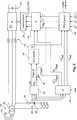
Die Struktur einer Ausführungsform der Erfindung gemäß
Der Wechselrichter
Der Wechseltrichter
Die Berechnung der Schaltzeiten basierend auf den Stromsollwerten durch den Toleranzbandblock
Ein wesentlicher Aspekt der vorliegenden Erfindung ist die Bestimmung dieser Sollwerte i1, i2 und i3 und/oder der Verlauf der drei Sollströme. Dabei ist der Verlauf der Sollströme auch im Zusammenhang mit dem Netzverhalten zu verstehen bzw. zu bewerten.An essential aspect of the present invention is the determination of these setpoint values i1 , i2 and i3 and / or the profile of the three setpoint currents. The course of the nominal currents should also be understood or evaluated in connection with the network behavior.
Um bedarfsgerecht ins Netz einzuspeisen – anstelle des Begriffes Netz kann auch synonym der Begriff Netzwerk verwendet werden – ist das Messfilter
Die gemessenen Spannungen uL1(p), uL2(t) und uL3(t) werden in den Transformationsblock
Diese Gleichungen und weitere Erläuterungen dazu sind im Übrigen in der bereits genannten deutschen Offenlegungsschrift
Die so bestimmte Netzspannung UN und der so bestimmte Netzphasenwinkel ϕN werden in den Zustandsbeobachterblock
Der Zustandsbeobachterblock
Eine mögliche Ausführung des Transformationsblocks
Der geschätzte Phasenwinkel ϕ wird direkt in einen Entscheidungsblock
Der Entscheidungsblock
Eine Zerlegung der gemessenen Spannungen U1(t), U2(t) und U3(t) in ein Mitsystem oder Gegensystem wird in dem Berechnungsblock
Der Entscheidungsblock
Ist das Flag 0, liegt also kein Fehlerfall vor, werden die drei Ströme wie folgt berechnet:
Der jeweilige Momentanwert des jeweiligen Sollstromes basiert somit auf dem Betrag des Mitsystemsollstroms I+, dem geschätzten Netzphasenwinkel φ und dem Phasenwinkel des Sollstromes des Mitsystems

Wenn das Flag den Wert 1 annimmt (Flag = 1) wird von einem Netzfehler ausgegangen. Zu solchen Netzfehlern oder Netzstörungen gehört:
- – der Verlust der Winkelstabilität,
- – das Auftreten einer Inselnetzbildung,
- – das Auftreten eines drei-phasigen Kurzschlusses, und
- – das Auftreten eines zwei-poligen Kurzschlusses.
- - the loss of angular stability,
- - the occurrence of islanding,
- The occurrence of a three-phase short circuit, and
- - the occurrence of a two-pole short circuit.
Weitere Ausführungen zu der Art solcher Netzstörungen finden sich auch in der bereits genannten Offenlegungsschrift
Bei Annahme eines Netzfehlers (Flag = 1) wird nach Berechnung bzw. Bestimmung der Sollströme i1(t), i2(t) und i3(t) in den folgenden drei Schritten vorgeschlagen. Die nachfolgenden Berechnungsschritte – und auch die oben genannte Berechnung im Fall ohne Netzfehler – erfolgt für jeden Zeitpunkt, an dem für die drei Sollströme i1(t), i2(t) und i3(t) jeweils ein Momentanwert an den Toleranzbandblock
Im ersten Schritt wird für das Mitsystem und das Gegensystem jeweils eine cos-KomponenteI+c undI–c sowie eine sin-KomponenteI+s bzw.I–s wie folgt berechnet:
In obigem Gleichungssystem des ersten Schrittes bezeichnetI+ den Betrag der Mitstromkomponente und entsprechendI– den Betrag der Gegenstromkomponente.

Es ist zu beachten, dass in dem Berechnungsblock
Aus den so berechneten cos- und sin-Komponenten für das Mitsystem als auch für das GegensystemI+c,I+s,I–c,I–s wird nun ein Hilfsstromwert i* und ein Hilfswinkelwert φ* im zweiten Schritt wie folgt berechnet:
Aus dem Hilfsstromwert i* und dem Hilfswinkelwert φ* wird schließlich im dritten Schritt für jeden der Sollströme i1(t), i2(t) und i3(t) jeweils ein Wert für den betreffenden Zeitpunkt wie folgt berechnet.
Es ist zu beachten, dass in diesem dritten Schritt drei einzelne Werte für die drei Sollströme i1(t), i2(t) und i3(t) berechnet werden. Dies erfolgt für jeden Berechnungszeitpunkt, also mehrfach für jede Periodendauer. Es ist weiter zu beachten, dass sich in jedem Zeitpunkt der Hilfsstromwert i* und der Hilfswinkelwert φ* verändern. Je nach Veränderung dieser Werte muss daher das Ergebnis der Berechnung dieses Schritts 3 nicht zu einem symmetrischen dreiphasigen Stromsystem führen, obwohl sich die drei Gleichungen der Berechnung des Schritts 3 nur in einem Winkeloffset von 2/3π bzw. 4/3π unterscheiden. Es ist also gleichwohl eine unsymmetrische Vorgabe der drei Ströme und damit unsymmetrische Einspeisung genauso möglich wie eine symmetrische Einspeisung. Dasselbe gilt im Übrigen auch sinngemäß für die oben dargestellte Berechnung der Sollströme i1(t), i2(t) und i3(t) in dem Entscheidungsblock
Die drei komplexen SpannungenU1,U2 undU3 definieren somit ein dreiphasiges Spannungssystem, das aber unsymmetrisch sein kann. Entsprechend erfolgt eine Zerlegung dieses dreiphasigen Systems in eine Mitsystemkomponente und eine Gegensystemkomponente basierend auf der Methode der symmetrischen Komponenten. Die Mitsystemkomponente, nämlich dessen Betrag U+fset und dessen Phase ϕU+fset wird in dem Mitsystemtransformationsblock
Die Berechnung eines Mitsystems, das auch als Mitsystemkomponente bezeichnet werden kann und eines Gegensystems, das auch als Gegensystemkomponente bezeichnet werden kann, ist grundsätzlich aus der Theorie der Methode der symmetrischen Komponenten bekannt. Dabei wir ein unsymmetrisches dreiphasiges System von sogenannten Phasoren in Mitsystem, Gegensystem und Nullsystem aufgeteilt. Das Mitsystem besitzt die gleiche Umlaufrichtung wie das zugrunde liegende dreiphasige System wohingegen das Gegensystem eine gegenläufige Richtung zu diesem ursprünglichen System aufweist. Das Mitsystem für sich gesehen und auch das Gegensystem für sich gesehen, sind jeweils in sich symmetrisch. Das Nullsystem bezeichnet ein System, bei dem alle Phasoren die gleiche Richtung und die gleiche Länge aufweisen. Dieses Nullsystem gleicht eine etwaige Abweichung von Null der Addition des ursprünglichen Systems aus. Im vorliegenden Fall wird aber – was auch dadurch begründet ist, dass ein Nullleiter nicht vorliegt bzw. nicht berücksichtigt wird – ein Nullsystem nicht betrachtet und damit auch nicht berechnet, sondern nur das Mitsystem bzw. die Mitsystemkomponente und das Gegensystem bzw. die Gegensystemkomponente.The calculation of a co-system, which can also be referred to as Mitsystemkomponente and a negative sequence system, which can also be referred to as a negative sequence component, is basically known from the theory of the method of symmetrical components. Here, we split an unbalanced three-phase system of so-called phasors into positive sequence, negative sequence and zero system. The co-system has the same orbital direction as the underlying three-phase system, whereas the counter-system has an opposite direction to this original system. The co-system itself, and also the counter-system itself, are each symmetrical. The zero system denotes a system in which all the phasors have the same direction and the same length. This zero system compensates for any deviation from zero in the addition of the original system. In the present case, however - and this is due to the fact that a neutral is not present or not considered - a zero system is not considered and therefore not calculated, but only the co-system or the Mitsystemkomponente and the negative sequence or the negative sequence component.
Die Berechnung eines Mitsystems und eines Gegensystems aus einem dreiphasigen, unsymmetrischen System ist dem Fachmann aus Lehrbüchern bekannt und wird insoweit hier nicht näher erläutert.The calculation of a positive sequence system and a negative sequence system from a three-phase, asymmetrical system is known to the person skilled in the art from textbooks and will not be explained in detail here.
Der Berechnung der komplexen SpannungswerteU1,U2 undU3, liegt das dem Grunde nach bekannte Verfahren einer diskreten Foriertransformation, kurz als DFT bezeichnet, zugrunde. Bei einer diskreten Foriertransformation wird ein periodisches Signal als Superposition, also Überlagerung eines Gleichanteils, einer Grundschwingung und ihrer Oberschwingung in eineindeutiger, d. h. umkehrbarer Weise beschrieben. Im einfachsten Fall liegt weder ein Gleichanteil noch eine Oberschwingung vor bzw. können solche Anteile vernachlässigt werden. In diesem Fall fallen die entsprechenden beschreibenden Komponenten weg und eine Beschreibung es Signals nach Betrag, Phase und Frequenz wird ausschließlich verwendet. Um eine solche diskrete Foriertransformation durchzuführen, ist eine Periodendauer des periodischen Signals zu erfassen. Liegt ein sinusförmiges Signal mit einer Frequenz von 50 Hz vor, wie das bei der elektrischen Spannung im europäischen Verbundnetz der Fall ist – sinngemäß ist dies auf ein 60 Hz-Netz wie beispielsweise in den U. S. A. übertragbar – so beträgt eine Periodenlänge T1/f = 1/50 Hz = 20 ms. Für eine diskrete Fouriertransformation des Spannungssignals eines 50 Hz-Spannungsnetzes werden also zumindest 20 ms benötigt. Diese Zeit kann sehr lang sein, wenn im Netz auf Netzfehler schnell reagiert werden soll.The calculation of the complex voltage valuesU1 ,U2 andU3 is based on the basically known method of a discrete Foriertransformation, referred to as DFT for short. In a discrete foriertransformation a periodic signal is described as a superposition, ie superposition of a DC component, a fundamental and its harmonic in a one-to-one, ie reversible way. In the simplest case, there is neither a direct component nor a harmonic or such components can be neglected. In this case, the corresponding descriptive components are omitted and a description of the signal by magnitude, phase and frequency is used exclusively. To perform such a discrete foriertransformation, a period of the periodic signal is to be detected. If a sinusoidal signal with a frequency of 50 Hz is present, as is the case with the electrical voltage in the European interconnected network - analogously, this can be applied to a 60 Hz network, for example in the USA - then a period length T1 / f = 1 / 50 Hz = 20 ms. For a discrete Fourier transformation of the voltage signal of a 50 Hz voltage network, at least 20 ms are required. This time can be very long if the network is to respond quickly to network errors.
Es wird nun vorgeschlagen, nur eine halbe Periodenlänge des zu transformierenden Signals zu verwenden. Vorliegend wird also von jedem Spannungssignal U1(t), U2(t) und U3(t) jeweils nur eine halbe Periodenlänge berücksichtig. Das Ergebnis dieser modifizierten DFT, die auch als Half-Cycle-DFT hier, bezeichnet wird, wird in dem Transformationsblock

Diese Berechnung wird für jede Phase berechnet, was durch den Index i angezeigt wird, der somit je nach Phase den Wert 1, 2 oder 3 annimmt. Somit wird zunächst ein erster Spannungsanteil Ui' und ein zweiter Spannungsanteil Ui'' mittels des jeweils angegebenen Integrals berechnet. Es wird somit nämlich ein bestimmtes Integral von 0 bis
Bei der Berechnung der beiden Integrale für den ersten und zweiten Spannungsanteil ist zu beachten, dass jeweils die bis zu einer halben Periodendauer zurückliegenden Spannungswerte von ui(t) berücksichtigt werden. Im Falle eines sinusförmigen Spannungssignales mit einer Frequenz von 50 Hz – um ein praktisches Beispiel zu nennen – ergibt sich eine halbe Periodendauer zu 10 ms. Demnach werden Änderungen etwa nach 10 ms durch diese modifizierte DFT bzw. Half-Cycle-DFT vollständig erfasst. Die ersten Auswirkungen haben solche Änderungen aber bereits bei ihrem Auftreten. Die in den Transformationsblock
Entsprechend ergibt sich auch nach etwa dieser Zeit eine Auswirkung bei den Werten des Mit- und Gegensystems, also für U+fset,

Der Zustandsschalter
Wird jedoch von einem Netzfehler ausgegangen, ist Flag = 1 und der Zustandsschalter
Der Phasenwinkel des Gegensystems,


Die Spannungsbeträge des Mitsystems U+fset und des Gegensystems U–fset, die im Berechnungsblock
Die Berechnung dieses vorgegebenen Stroms kann verschiedene Vorgaben berücksichtigen, nämlich den einzuspeisenden Wirkleistungsanteil, insbesondere den Wirkleistungsanteil des Mitsystems P+ und den einzuspeisende Blindleistungsanteil, nämlich insbesondere den Wirkleistungsanteil des Mitsystems Q+. Weiterhin kann ein Verhältnis der Beträge des Stromes des Gegensystems I– zu dem Strom des Mitsystems I+, nämlich I–/I+ berücksichtigt werden. Dieser Quotient ist ein Maß für den Unsymmetriegrad des dreiphasigen Systems, das durch diese Mitsystemkomponente und Gegensystemkoponente beschrieben wird.The calculation of this predetermined current can take into account various requirements, namely the active power component to be fed in, in particular the active power component of the positive system P+ and the reactive power component to be fed in, namely in particular the effective power component of the positive sequence system Q+ . Furthermore, a ratio of the amounts of the current of the negative sequence I- to the current of the Mitsystems I+ , namely I- / I+ be taken into account. This quotient is a measure of the degree of asymmetry of the three-phase system, which is described by this Mitsystemkomponente and Gegensystemkoponente.
Weiterhin berücksichtigt der PQ-Steuerungsblock
Der PQ-Block kann auf unterschiedliche Arten und Weisen ausgeführt sein. Er kann z. B. U+fset und U–fset und U gleichzeitig berücksichtigen. Beispielsweise müssen U+fset und U–fset, die im Grunde synthetische Werte sind, U, das für die reale Spannung steht, nicht korrekt wiedergeben. So können U+fset und U–fset bspw. einen Frequenzfehler haben. Abhängig von der konkreten Situation wird die eine oder die andere oder beide Werte verwendet.The PQ block can be implemented in different ways. He can z. For example, consider U+fset and U-fset and U at the same time. For example, U+fset and U-fset , which are basically synthetic values, U must not correctly represent the real voltage. For example, U+fset and U-fset may have a frequencyerror . Depending on the specific situation, one or the other or both values are used.
ZITATE ENTHALTEN IN DER BESCHREIBUNG QUOTES INCLUDE IN THE DESCRIPTION
Diese Liste der vom Anmelder aufgeführten Dokumente wurde automatisiert erzeugt und ist ausschließlich zur besseren Information des Lesers aufgenommen. Die Liste ist nicht Bestandteil der deutschen Patent- bzw. Gebrauchsmusteranmeldung. Das DPMA übernimmt keinerlei Haftung für etwaige Fehler oder Auslassungen.This list of the documents listed by the applicant has been generated automatically and is included solely for the better information of the reader. The list is not part of the German patent or utility model application. The DPMA assumes no liability for any errors or omissions.
Zitierte PatentliteraturCited patent literature
- DE 10022974 A1[0003]DE 10022974 A1[0003]
- DE 10119624 A1[0003]DE 10119624 A1[0003]
- WO 02/086315 A1[0003]WO 02/086315 A1[0003]
- DE 19756777 A1[0003]DE 19756777 A1[0003]
- DE 102009031017 A1[0017, 0022, 0058, 0060, 0063, 0071]DE 102009031017 A1[0017, 0022, 0058, 0060, 0063, 0071]
Claims (15)
Translated fromGermanPriority Applications (24)
| Application Number | Priority Date | Filing Date | Title |
|---|---|---|---|
| DE102011084910ADE102011084910A1 (en) | 2011-10-20 | 2011-10-20 | Method and device for feeding electrical current into an electrical network |
| RU2014120171ARU2613357C2 (en) | 2011-10-20 | 2012-10-10 | Method and device for electric current input into electric network |
| CN201280051810.9ACN103891081B (en) | 2011-10-20 | 2012-10-10 | Method and device for feeding electric current into a grid |
| AU2012325039AAU2012325039B2 (en) | 2011-10-20 | 2012-10-10 | Method and apparatus for feeding electrical current into an electrical power supply system |
| ES14176502TES2727631T3 (en) | 2011-10-20 | 2012-10-10 | Procedure and device for the supply of electrical current in an electrical network |
| BR112014009345ABR112014009345A2 (en) | 2011-10-20 | 2012-10-10 | Method for supplying electric current in a three phase power grid, wind power installation, and wind farm |
| EP14176502.4AEP2806523B1 (en) | 2011-10-20 | 2012-10-10 | Method and apparatus for feeding electrical current into an electrical power supply system |
| ES12784480TES2774281T3 (en) | 2011-10-20 | 2012-10-10 | Procedure for supplying electrical current in an electrical network |
| PT14176502TPT2806523T (en) | 2011-10-20 | 2012-10-10 | Method and apparatus for feeding electrical current into an electrical power supply system |
| CA2848362ACA2848362C (en) | 2011-10-20 | 2012-10-10 | Method and apparatus for feeding electrical current into an electrical power supply system |
| DK12784480.1TDK2769448T3 (en) | 2011-10-20 | 2012-10-10 | Method of feeding electric power to a power grid |
| MX2014004237AMX2014004237A (en) | 2011-10-20 | 2012-10-10 | Method and apparatus for feeding electrical current into an electrical power supply system. |
| PCT/EP2012/070089WO2013057028A1 (en) | 2011-10-20 | 2012-10-10 | Method and apparatus for feeding electrical current into an electrical power supply system |
| JP2014536189AJP5933016B2 (en) | 2011-10-20 | 2012-10-10 | Method and apparatus for supplying current to a power system |
| PT127844801TPT2769448T (en) | 2011-10-20 | 2012-10-10 | Method and apparatus for feeding electrical current into an electrical power supply system |
| DK14176502.4TDK2806523T3 (en) | 2011-10-20 | 2012-10-10 | Method and device for supplying electric power to a power grid |
| NZ622293ANZ622293B2 (en) | 2011-10-20 | 2012-10-10 | Method and apparatus for feeding electrical current into an electrical power supply system |
| KR1020147013344AKR101657855B1 (en) | 2011-10-20 | 2012-10-10 | Method and apparatus for feeding electrical current into an electrical power supply system |
| EP12784480.1AEP2769448B1 (en) | 2011-10-20 | 2012-10-10 | Method for feeding electrical current into a power grid |
| US14/352,250US9362837B2 (en) | 2011-10-20 | 2012-10-10 | Method and apparatus for feeding electrical current into an electrical power supply system |
| TW101138769ATWI559644B (en) | 2011-10-20 | 2012-10-19 | Method for feeding electric current into an electric network, wind power installation and wind park |
| ARP120103905AAR088396A1 (en) | 2011-10-20 | 2012-10-19 | PROCEDURE AND DEVICE FOR POWERING AN ELECTRICAL NETWORK WITH ELECTRICAL CURRENT |
| ZA2014/01761AZA201401761B (en) | 2011-10-20 | 2014-03-11 | Method and apparatus for feeding electrical current into an electrical power supply system |
| CL2014000977ACL2014000977A1 (en) | 2011-10-20 | 2014-04-16 | Procedure for feeding an electrical network, three-phase network with first, second and third phase under first, second and third voltage with network frequency, which comprises measuring the voltages, transforming the voltages into a voltage cosystem and a contra-system according to the method of symmetric components, calculate a first, second and third theoretical electric current, where these are calculated based on at least one value of the cosystem and / or counter-system; electric power installation |
Applications Claiming Priority (1)
| Application Number | Priority Date | Filing Date | Title |
|---|---|---|---|
| DE102011084910ADE102011084910A1 (en) | 2011-10-20 | 2011-10-20 | Method and device for feeding electrical current into an electrical network |
Publications (1)
| Publication Number | Publication Date |
|---|---|
| DE102011084910A1true DE102011084910A1 (en) | 2013-04-25 |
Family
ID=47177908
Family Applications (1)
| Application Number | Title | Priority Date | Filing Date |
|---|---|---|---|
| DE102011084910ACeasedDE102011084910A1 (en) | 2011-10-20 | 2011-10-20 | Method and device for feeding electrical current into an electrical network |
Country Status (19)
| Country | Link |
|---|---|
| US (1) | US9362837B2 (en) |
| EP (2) | EP2806523B1 (en) |
| JP (1) | JP5933016B2 (en) |
| KR (1) | KR101657855B1 (en) |
| CN (1) | CN103891081B (en) |
| AR (1) | AR088396A1 (en) |
| AU (1) | AU2012325039B2 (en) |
| BR (1) | BR112014009345A2 (en) |
| CA (1) | CA2848362C (en) |
| CL (1) | CL2014000977A1 (en) |
| DE (1) | DE102011084910A1 (en) |
| DK (2) | DK2806523T3 (en) |
| ES (2) | ES2727631T3 (en) |
| MX (1) | MX2014004237A (en) |
| PT (2) | PT2769448T (en) |
| RU (1) | RU2613357C2 (en) |
| TW (1) | TWI559644B (en) |
| WO (1) | WO2013057028A1 (en) |
| ZA (1) | ZA201401761B (en) |
Cited By (8)
| Publication number | Priority date | Publication date | Assignee | Title |
|---|---|---|---|---|
| DE102012212777A1 (en) | 2012-07-20 | 2014-01-23 | Wobben Properties Gmbh | Method for controlling a wind farm |
| WO2015022206A1 (en)* | 2013-08-15 | 2015-02-19 | Wobben Properties Gmbh | Method for feeding electric power into a supply grid |
| WO2016012411A1 (en)* | 2014-07-24 | 2016-01-28 | Alstom Technology Ltd | A voltage source converter |
| WO2017016870A1 (en)* | 2015-07-24 | 2017-02-02 | Wobben Properties Gmbh | Method and device for detecting an electrical voltage in a supply network |
| WO2017129749A1 (en)* | 2016-01-27 | 2017-08-03 | Wobben Properties Gmbh | Method for feeding electrical power into an electric supply network |
| DE102019105861A1 (en)* | 2019-03-07 | 2020-09-10 | Sma Solar Technology Ag | Method and device for the approximate determination of voltages on a high-voltage side of a transformer |
| US10958077B2 (en) | 2016-09-23 | 2021-03-23 | Wobben Properties Gmbh | Method for generating an alternating current by means of an inverter of a wind turbine |
| CN117849692A (en)* | 2024-03-08 | 2024-04-09 | 武汉格蓝若智能技术股份有限公司 | Method and system for monitoring phase sequence abnormality of secondary circuit of transformer in transformer substation |
Families Citing this family (18)
| Publication number | Priority date | Publication date | Assignee | Title |
|---|---|---|---|---|
| ES2260497T7 (en) | 2001-11-21 | 2009-11-05 | Millennium Pharmaceuticals, Inc. | ANTAGONISTS OF CHEMIOKININE RECEPTORS AND METHODS OF USE OF THE SAME. |
| DE102012220582A1 (en)* | 2012-11-12 | 2014-07-03 | Wobben Properties Gmbh | Wind energy plant and method for feeding electrical energy |
| DE102013210812A1 (en) | 2013-06-10 | 2014-12-11 | Wobben Properties Gmbh | Method for feeding electrical power into an electrical supply network |
| GB2515358B (en)* | 2013-11-06 | 2017-01-18 | Reactive Tech Ltd | Grid Frequency Response |
| DE102014219052A1 (en)* | 2014-09-22 | 2016-03-24 | Wobben Properties Gmbh | Method for generating an alternating electrical current |
| CN105790298B (en)* | 2014-12-23 | 2019-03-12 | 台达电子工业股份有限公司 | wind power generation control device and wind power generation system |
| CN105552953A (en)* | 2015-12-15 | 2016-05-04 | 云南电网有限责任公司电力科学研究院 | Fully-open real-time monitoring dual-fed wind power generation test system |
| CN105591402B (en)* | 2016-01-28 | 2018-05-04 | 云南电网有限责任公司电力科学研究院 | A kind of modeling and simulation method and apparatus of direct-drive permanent-magnetism Wind turbines |
| CN105576675B (en)* | 2016-01-28 | 2018-05-15 | 云南电网有限责任公司电力科学研究院 | A kind of method and system of the damping control of the electric system containing more Fans |
| DE102016107614A1 (en)* | 2016-04-25 | 2017-10-26 | Wobben Properties Gmbh | Inverter and method for generating an alternating current |
| CN107480406B (en)* | 2017-08-02 | 2020-09-08 | 华北水利水电大学 | A dynamic vector model building method for short-circuit current calculation of doubly-fed wind turbines |
| US10847211B2 (en)* | 2018-04-18 | 2020-11-24 | Arm Limited | Latch circuitry for memory applications |
| EP3813218A1 (en)* | 2019-10-25 | 2021-04-28 | Wobben Properties GmbH | Arrangement for feeding electric power into an electricity supply network |
| EP3840160A1 (en)* | 2019-12-16 | 2021-06-23 | Wobben Properties GmbH | Method for controlling a wind energy system |
| CN111475929B (en)* | 2020-03-20 | 2022-12-20 | 广西电网有限责任公司电力科学研究院 | Inversion verification method and system based on monitoring data of power distribution network real-world test platform |
| CN114509639A (en)* | 2020-11-17 | 2022-05-17 | 国网河南省电力公司封丘县供电公司 | Power distribution network fault section judgment method and system based on fault current positive sequence component |
| US12300338B2 (en) | 2022-06-14 | 2025-05-13 | Arm Limited | Configurable scan chain architecture for multi-port memory |
| KR102704617B1 (en)* | 2022-10-18 | 2024-09-11 | 울산광역시 | Artificial intelligence wind power generation forecasting device |
Citations (6)
| Publication number | Priority date | Publication date | Assignee | Title |
|---|---|---|---|---|
| DE19756777A1 (en) | 1997-12-19 | 1999-07-01 | Aloys Wobben | Method for operating a wind energy installation and wind energy installation |
| DE10022974A1 (en) | 2000-05-11 | 2001-11-22 | Aloys Wobben | Control of wind power generator plant feeding grid, regulates power delivery as a function of measured grid frequency |
| WO2002086315A1 (en) | 2001-04-24 | 2002-10-31 | Aloys Wobben | Method for operating a wind energy plant |
| DE10119624A1 (en) | 2001-04-20 | 2002-11-21 | Aloys Wobben | Operating wind energy plant involves regulating power delivered from generator to electrical load, especially of electrical network, depending on current delivered to the load |
| WO2010028689A1 (en)* | 2008-09-11 | 2010-03-18 | Woodward Seg Gmbh & Co. Kg | Direct power control with component separation |
| DE102009031017A1 (en) | 2009-06-29 | 2011-02-03 | Wobben, Aloys, Dipl.-Ing. | Method and device for network state observation |
Family Cites Families (27)
| Publication number | Priority date | Publication date | Assignee | Title |
|---|---|---|---|---|
| RU2105403C1 (en)* | 1996-04-09 | 1998-02-20 | Юрий Сергеевич Макаров | Supply mains voltage unbalance corrector |
| DE19737590C1 (en)* | 1997-08-28 | 1998-10-22 | Siemens Ag | Voltage supply quality improvement method e.g. for automated processes |
| JP3428885B2 (en)* | 1997-12-10 | 2003-07-22 | 三菱電機株式会社 | Synchronous machine simulator and synchronous machine simulation method |
| JP2001231169A (en)* | 2000-02-18 | 2001-08-24 | Sato Benec Co Ltd | Compensating device for unbalanced load in distribution system and building facility |
| JP2004180363A (en)* | 2002-11-25 | 2004-06-24 | Tm T & D Kk | Reversed phase voltage compensation system for power grid system |
| JP2006025549A (en)* | 2004-07-08 | 2006-01-26 | Tokyo Electric Power Co Inc:The | Power supply device and power system including the same |
| JP4220973B2 (en)* | 2005-02-28 | 2009-02-04 | 三菱重工業株式会社 | Wind power generator and control method for wind power generator |
| CH697550B1 (en)* | 2005-03-30 | 2008-11-28 | Alstom Technology Ltd | Method for controlling a frequency converter. |
| US7423412B2 (en)* | 2006-01-31 | 2008-09-09 | General Electric Company | Method, apparatus and computer program product for injecting current |
| DE102006050077A1 (en)* | 2006-10-24 | 2008-05-08 | Repower Systems Ag | Inverter with controllable phase angle |
| US7725295B2 (en)* | 2006-11-01 | 2010-05-25 | Abb Research Ltd. | Cable fault detection |
| DE102006054870A1 (en)* | 2006-11-20 | 2008-06-12 | Repower Systems Ag | Wind turbine with negative sequence control and operating procedure |
| JP5047278B2 (en)* | 2007-05-08 | 2012-10-10 | 三菱電機株式会社 | Power quality compensator |
| CN100530889C (en)* | 2007-06-04 | 2009-08-19 | 天津大学 | Integrated power quality adjustment control method and device |
| DE102007049251A1 (en)* | 2007-10-12 | 2009-04-23 | Repower Systems Ag | Wind turbines with regulation for network faults and operating methods therefor |
| CN101809837B (en)* | 2007-12-14 | 2013-10-16 | 三菱重工业株式会社 | wind power plant |
| DE102008034532A1 (en)* | 2008-02-20 | 2009-08-27 | Repower Systems Ag | Wind turbine with inverter control |
| JP5408889B2 (en)* | 2008-03-18 | 2014-02-05 | 川崎重工業株式会社 | Power converter |
| JP4834691B2 (en)* | 2008-05-09 | 2011-12-14 | 株式会社日立製作所 | Wind power generation system |
| CN101557190A (en) | 2009-01-22 | 2009-10-14 | 北京清能华福风电技术有限公司 | Control method of net-side rectifier of double-fed asynchronous wind power generator under unbalanced network voltage |
| CN101534065B (en) | 2009-04-20 | 2010-12-01 | 浙江大学 | Asymmetric direct power control method for grid-connected three-phase voltage source converter |
| JP5004366B2 (en)* | 2009-12-07 | 2012-08-22 | 株式会社京三製作所 | Unbalance voltage compensation method, unbalance voltage compensation device, control method for three-phase converter, and control device for three-phase converter |
| US7978445B2 (en)* | 2009-12-31 | 2011-07-12 | General Electric Company | Systems and apparatus relating to wind turbine electrical control and operation |
| DE102010015440A1 (en)* | 2010-04-16 | 2011-10-20 | Kenersys Gmbh | Method for power supply and power supply system |
| WO2012031992A2 (en)* | 2010-09-06 | 2012-03-15 | Sma Solar Technology Ag | Method for stabilizing an electric grid |
| CN102055205A (en) | 2010-10-26 | 2011-05-11 | 天津理工大学 | Voltage unbalanced mathematical model-based control strategy for brushless double-feed motor grid-side converter |
| US9382898B2 (en)* | 2010-11-10 | 2016-07-05 | Vestas Wind Systems A/S | Wind turbine power production using positive and negative sequence current component parameters generated based on operational mode |
- 2011
- 2011-10-20DEDE102011084910Apatent/DE102011084910A1/ennot_activeCeased
- 2012
- 2012-10-10PTPT127844801Tpatent/PT2769448T/enunknown
- 2012-10-10ESES14176502Tpatent/ES2727631T3/enactiveActive
- 2012-10-10AUAU2012325039Apatent/AU2012325039B2/enactiveActive
- 2012-10-10WOPCT/EP2012/070089patent/WO2013057028A1/enactiveApplication Filing
- 2012-10-10PTPT14176502Tpatent/PT2806523T/enunknown
- 2012-10-10JPJP2014536189Apatent/JP5933016B2/enactiveActive
- 2012-10-10DKDK14176502.4Tpatent/DK2806523T3/enactive
- 2012-10-10ESES12784480Tpatent/ES2774281T3/enactiveActive
- 2012-10-10USUS14/352,250patent/US9362837B2/enactiveActive
- 2012-10-10KRKR1020147013344Apatent/KR101657855B1/ennot_activeExpired - Fee Related
- 2012-10-10CACA2848362Apatent/CA2848362C/enactiveActive
- 2012-10-10CNCN201280051810.9Apatent/CN103891081B/enactiveActive
- 2012-10-10EPEP14176502.4Apatent/EP2806523B1/enactiveActive
- 2012-10-10EPEP12784480.1Apatent/EP2769448B1/enactiveActive
- 2012-10-10BRBR112014009345Apatent/BR112014009345A2/ennot_activeApplication Discontinuation
- 2012-10-10RURU2014120171Apatent/RU2613357C2/ennot_activeIP Right Cessation
- 2012-10-10DKDK12784480.1Tpatent/DK2769448T3/enactive
- 2012-10-10MXMX2014004237Apatent/MX2014004237A/enactiveIP Right Grant
- 2012-10-19TWTW101138769Apatent/TWI559644B/ennot_activeIP Right Cessation
- 2012-10-19ARARP120103905Apatent/AR088396A1/enactiveIP Right Grant
- 2014
- 2014-03-11ZAZA2014/01761Apatent/ZA201401761B/enunknown
- 2014-04-16CLCL2014000977Apatent/CL2014000977A1/enunknown
Patent Citations (6)
| Publication number | Priority date | Publication date | Assignee | Title |
|---|---|---|---|---|
| DE19756777A1 (en) | 1997-12-19 | 1999-07-01 | Aloys Wobben | Method for operating a wind energy installation and wind energy installation |
| DE10022974A1 (en) | 2000-05-11 | 2001-11-22 | Aloys Wobben | Control of wind power generator plant feeding grid, regulates power delivery as a function of measured grid frequency |
| DE10119624A1 (en) | 2001-04-20 | 2002-11-21 | Aloys Wobben | Operating wind energy plant involves regulating power delivered from generator to electrical load, especially of electrical network, depending on current delivered to the load |
| WO2002086315A1 (en) | 2001-04-24 | 2002-10-31 | Aloys Wobben | Method for operating a wind energy plant |
| WO2010028689A1 (en)* | 2008-09-11 | 2010-03-18 | Woodward Seg Gmbh & Co. Kg | Direct power control with component separation |
| DE102009031017A1 (en) | 2009-06-29 | 2011-02-03 | Wobben, Aloys, Dipl.-Ing. | Method and device for network state observation |
Cited By (20)
| Publication number | Priority date | Publication date | Assignee | Title |
|---|---|---|---|---|
| EP4181339A1 (en) | 2012-07-20 | 2023-05-17 | Wobben Properties GmbH | Method for controlling a wind farm |
| DE102012212777A1 (en) | 2012-07-20 | 2014-01-23 | Wobben Properties Gmbh | Method for controlling a wind farm |
| WO2015022206A1 (en)* | 2013-08-15 | 2015-02-19 | Wobben Properties Gmbh | Method for feeding electric power into a supply grid |
| RU2651804C2 (en)* | 2013-08-15 | 2018-04-24 | Воббен Пропертиз Гмбх | Method for feeding electrical power into a supply grid |
| US10132294B2 (en) | 2013-08-15 | 2018-11-20 | Wobben Properties Gmbh | Method for feeding electric power into a supply grid |
| WO2016012411A1 (en)* | 2014-07-24 | 2016-01-28 | Alstom Technology Ltd | A voltage source converter |
| EP3172825B1 (en)* | 2014-07-24 | 2023-03-01 | General Electric Technology GmbH | A voltage source converter |
| US10840703B2 (en) | 2015-07-24 | 2020-11-17 | Wobben Properties Gmbh | Method and device for detecting an electrical voltage in a supply network |
| WO2017016870A1 (en)* | 2015-07-24 | 2017-02-02 | Wobben Properties Gmbh | Method and device for detecting an electrical voltage in a supply network |
| CN107851995A (en)* | 2015-07-24 | 2018-03-27 | 乌本产权有限公司 | For detecting the method and apparatus for supplying the voltage in power network |
| CN107851995B (en)* | 2015-07-24 | 2021-04-02 | 乌本产权有限公司 | Method and device for detecting a voltage in a supply network |
| US10794364B2 (en) | 2016-01-27 | 2020-10-06 | Wobben Properties Gmbh | Method for feeding electrical power into an electric supply network |
| CN108604798B (en)* | 2016-01-27 | 2022-02-01 | 乌本产权有限公司 | Method for feeding electrical power into a power supply network |
| CN108604798A (en)* | 2016-01-27 | 2018-09-28 | 乌本产权有限公司 | For by the method in electrical power feed-in power supply network |
| WO2017129749A1 (en)* | 2016-01-27 | 2017-08-03 | Wobben Properties Gmbh | Method for feeding electrical power into an electric supply network |
| US10958077B2 (en) | 2016-09-23 | 2021-03-23 | Wobben Properties Gmbh | Method for generating an alternating current by means of an inverter of a wind turbine |
| EP3516763B1 (en)* | 2016-09-23 | 2022-10-12 | Wobben Properties GmbH | Method for generating an alternating current by means of an inverter of a wind turbine |
| DE102019105861A1 (en)* | 2019-03-07 | 2020-09-10 | Sma Solar Technology Ag | Method and device for the approximate determination of voltages on a high-voltage side of a transformer |
| CN117849692A (en)* | 2024-03-08 | 2024-04-09 | 武汉格蓝若智能技术股份有限公司 | Method and system for monitoring phase sequence abnormality of secondary circuit of transformer in transformer substation |
| CN117849692B (en)* | 2024-03-08 | 2024-05-31 | 武汉格蓝若智能技术股份有限公司 | Method and system for monitoring phase sequence abnormality of secondary circuit of transformer in transformer substation |
Also Published As
| Publication number | Publication date |
|---|---|
| BR112014009345A2 (en) | 2017-04-18 |
| WO2013057028A1 (en) | 2013-04-25 |
| CA2848362A1 (en) | 2013-04-25 |
| ZA201401761B (en) | 2014-12-23 |
| CN103891081A (en) | 2014-06-25 |
| US20140254216A1 (en) | 2014-09-11 |
| PT2806523T (en) | 2019-06-17 |
| TW201338335A (en) | 2013-09-16 |
| AR088396A1 (en) | 2014-05-28 |
| KR101657855B1 (en) | 2016-09-20 |
| RU2014120171A (en) | 2015-11-27 |
| DK2769448T3 (en) | 2020-03-30 |
| CL2014000977A1 (en) | 2014-07-25 |
| EP2769448A1 (en) | 2014-08-27 |
| CA2848362C (en) | 2016-12-20 |
| DK2806523T3 (en) | 2019-05-20 |
| EP2806523B1 (en) | 2019-03-13 |
| ES2727631T3 (en) | 2019-10-17 |
| EP2806523A2 (en) | 2014-11-26 |
| RU2613357C2 (en) | 2017-03-16 |
| JP5933016B2 (en) | 2016-06-08 |
| MX2014004237A (en) | 2014-06-11 |
| JP2014531184A (en) | 2014-11-20 |
| ES2774281T3 (en) | 2020-07-20 |
| AU2012325039A1 (en) | 2014-03-27 |
| TWI559644B (en) | 2016-11-21 |
| AU2012325039B2 (en) | 2015-11-19 |
| PT2769448T (en) | 2020-03-13 |
| CN103891081B (en) | 2017-02-22 |
| KR20140079492A (en) | 2014-06-26 |
| NZ622293A (en) | 2016-05-27 |
| EP2806523A3 (en) | 2015-03-18 |
| EP2769448B1 (en) | 2019-12-25 |
| US9362837B2 (en) | 2016-06-07 |
Similar Documents
| Publication | Publication Date | Title |
|---|---|---|
| EP2806523B1 (en) | Method and apparatus for feeding electrical current into an electrical power supply system | |
| EP3818608B1 (en) | Method for controlling a wind farm in order to damp subsynchronous oscillations | |
| EP2872777B1 (en) | Method for controlling an electric generator | |
| EP2179498B1 (en) | Method and apparatus for compensation of vibration effects of network asymmetry in a doubly-fed asynchronous machine | |
| EP3008334B1 (en) | Method for feeding electric power into an electric supply network | |
| EP2449387B1 (en) | Method and device for monitoring the state of a network | |
| EP3011668B1 (en) | Control method for self-commutated converter for controlling power exchange | |
| EP2873129B1 (en) | Method and apparatus for feeding electric energy into an electric supply network | |
| EP2917989B1 (en) | Wind power plant and method for supplying electrical energy | |
| EP2614573B1 (en) | Method for stabilizing an electric grid | |
| DE102011054002B4 (en) | Decentralized power generation plant with device and method for island detection | |
| WO2017016870A1 (en) | Method and device for detecting an electrical voltage in a supply network | |
| EP4181339A1 (en) | Method for controlling a wind farm | |
| EP3836337A1 (en) | Procedure for current limiting of a virtual synchronous machine, in particular during a mains fault | |
| EP3033816B1 (en) | Method for feeding electric power into a supply grid | |
| EP3818384A1 (en) | Wind energy system and method for identifying low-frequency oscillations in an electrical supply network | |
| EP3032686A1 (en) | Method for current control | |
| EP3890136A1 (en) | Method for operating a converter, in particular a wind energy plant | |
| DE102019105861A1 (en) | Method and device for the approximate determination of voltages on a high-voltage side of a transformer | |
| EP3311481B1 (en) | Method for controlling a voltage source inverter, voltage source inverter, and installation for transferring electrical energy | |
| DE102017108637A1 (en) | Method for detecting islanding | |
| DE102007041793B4 (en) | Method and device for determining the losses of an energy converter, in particular a power converter or synchronous generator, and associated energy converter | |
| EP3840160A1 (en) | Method for controlling a wind energy system | |
| EP4099531A1 (en) | Method for determining network parameters for controlling a petersen coil | |
| EP2639955A2 (en) | Method for regulating a self-regulated frequency converter |
Legal Events
| Date | Code | Title | Description |
|---|---|---|---|
| R012 | Request for examination validly filed | ||
| R082 | Change of representative | Representative=s name:EISENFUEHR SPEISER PATENTANWAELTE RECHTSANWAEL, DE Representative=s name:EISENFUEHR, SPEISER & PARTNER, DE | |
| R002 | Refusal decision in examination/registration proceedings | ||
| R003 | Refusal decision now final |