DE102011083063B4 - Method for generating planning data for an implant - Google Patents
Method for generating planning data for an implantDownload PDFInfo
- Publication number
- DE102011083063B4 DE102011083063B4DE102011083063.4ADE102011083063ADE102011083063B4DE 102011083063 B4DE102011083063 B4DE 102011083063B4DE 102011083063 ADE102011083063 ADE 102011083063ADE 102011083063 B4DE102011083063 B4DE 102011083063B4
- Authority
- DE
- Germany
- Prior art keywords
- image data
- data
- implant
- patient
- generated
- Prior art date
- Legal status (The legal status is an assumption and is not a legal conclusion. Google has not performed a legal analysis and makes no representation as to the accuracy of the status listed.)
- Active
Links
Images


Classifications
- G—PHYSICS
- G06—COMPUTING OR CALCULATING; COUNTING
- G06T—IMAGE DATA PROCESSING OR GENERATION, IN GENERAL
- G06T19/00—Manipulating 3D models or images for computer graphics
- G—PHYSICS
- G06—COMPUTING OR CALCULATING; COUNTING
- G06T—IMAGE DATA PROCESSING OR GENERATION, IN GENERAL
- G06T7/00—Image analysis
- G06T7/30—Determination of transform parameters for the alignment of images, i.e. image registration
- G—PHYSICS
- G16—INFORMATION AND COMMUNICATION TECHNOLOGY [ICT] SPECIALLY ADAPTED FOR SPECIFIC APPLICATION FIELDS
- G16H—HEALTHCARE INFORMATICS, i.e. INFORMATION AND COMMUNICATION TECHNOLOGY [ICT] SPECIALLY ADAPTED FOR THE HANDLING OR PROCESSING OF MEDICAL OR HEALTHCARE DATA
- G16H20/00—ICT specially adapted for therapies or health-improving plans, e.g. for handling prescriptions, for steering therapy or for monitoring patient compliance
- G16H20/40—ICT specially adapted for therapies or health-improving plans, e.g. for handling prescriptions, for steering therapy or for monitoring patient compliance relating to mechanical, radiation or invasive therapies, e.g. surgery, laser therapy, dialysis or acupuncture
- G—PHYSICS
- G16—INFORMATION AND COMMUNICATION TECHNOLOGY [ICT] SPECIALLY ADAPTED FOR SPECIFIC APPLICATION FIELDS
- G16H—HEALTHCARE INFORMATICS, i.e. INFORMATION AND COMMUNICATION TECHNOLOGY [ICT] SPECIALLY ADAPTED FOR THE HANDLING OR PROCESSING OF MEDICAL OR HEALTHCARE DATA
- G16H30/00—ICT specially adapted for the handling or processing of medical images
- G16H30/40—ICT specially adapted for the handling or processing of medical images for processing medical images, e.g. editing
- G—PHYSICS
- G16—INFORMATION AND COMMUNICATION TECHNOLOGY [ICT] SPECIALLY ADAPTED FOR SPECIFIC APPLICATION FIELDS
- G16H—HEALTHCARE INFORMATICS, i.e. INFORMATION AND COMMUNICATION TECHNOLOGY [ICT] SPECIALLY ADAPTED FOR THE HANDLING OR PROCESSING OF MEDICAL OR HEALTHCARE DATA
- G16H50/00—ICT specially adapted for medical diagnosis, medical simulation or medical data mining; ICT specially adapted for detecting, monitoring or modelling epidemics or pandemics
- G16H50/50—ICT specially adapted for medical diagnosis, medical simulation or medical data mining; ICT specially adapted for detecting, monitoring or modelling epidemics or pandemics for simulation or modelling of medical disorders
- G—PHYSICS
- G06—COMPUTING OR CALCULATING; COUNTING
- G06T—IMAGE DATA PROCESSING OR GENERATION, IN GENERAL
- G06T2207/00—Indexing scheme for image analysis or image enhancement
- G06T2207/10—Image acquisition modality
- G06T2207/10072—Tomographic images
- G—PHYSICS
- G06—COMPUTING OR CALCULATING; COUNTING
- G06T—IMAGE DATA PROCESSING OR GENERATION, IN GENERAL
- G06T2207/00—Indexing scheme for image analysis or image enhancement
- G06T2207/10—Image acquisition modality
- G06T2207/10116—X-ray image
- G—PHYSICS
- G06—COMPUTING OR CALCULATING; COUNTING
- G06T—IMAGE DATA PROCESSING OR GENERATION, IN GENERAL
- G06T2207/00—Indexing scheme for image analysis or image enhancement
- G06T2207/30—Subject of image; Context of image processing
- G06T2207/30004—Biomedical image processing
- G06T2207/30008—Bone
- G—PHYSICS
- G06—COMPUTING OR CALCULATING; COUNTING
- G06T—IMAGE DATA PROCESSING OR GENERATION, IN GENERAL
- G06T2210/00—Indexing scheme for image generation or computer graphics
- G06T2210/41—Medical
Landscapes
- Engineering & Computer Science (AREA)
- Health & Medical Sciences (AREA)
- Medical Informatics (AREA)
- Public Health (AREA)
- Epidemiology (AREA)
- General Health & Medical Sciences (AREA)
- Primary Health Care (AREA)
- Nuclear Medicine, Radiotherapy & Molecular Imaging (AREA)
- Theoretical Computer Science (AREA)
- General Physics & Mathematics (AREA)
- Physics & Mathematics (AREA)
- Computer Hardware Design (AREA)
- Computer Graphics (AREA)
- General Engineering & Computer Science (AREA)
- Software Systems (AREA)
- Radiology & Medical Imaging (AREA)
- Urology & Nephrology (AREA)
- Surgery (AREA)
- Biomedical Technology (AREA)
- Data Mining & Analysis (AREA)
- Databases & Information Systems (AREA)
- Pathology (AREA)
- Computer Vision & Pattern Recognition (AREA)
- Apparatus For Radiation Diagnosis (AREA)
Abstract
Translated fromGermanDescription
Translated fromGermanDie Erfindung betrifft ein Verfahren zum Erzeugen von Planungsdaten, die mit einer Platzierung eines Implantats an einem Einsatzort in einem Patienten korreliert sind.The invention relates to a method for generating planning data which are correlated with a placement of an implant at a point of use in a patient.
Viele Patienten, die z.B. eine Fraktur an ihren Knochen erlitten haben, benötigen eine chirurgische Versorgung mit einem Implantat. Das Implantat ist hierbei an einem Einsatzort im Patienten, also z.B. zur Überbrückung und Fixierung der Fraktur, zu platzieren. Bei einer chirurgischen Versorgung mit einem Implantat wird eine 2D-Bildgebung gegenüber einer 3D-Bildgebung, in der Regel Röntgenbildgebung bevorzugt, da der Patient mit einer geringeren Strahlendosis belastet wird und eine 2D-Bildgebung - bzw. das entsprechende Bildgebungssystem - besser handhabbar ist. Mit einer 2D-Bildgebung ist jedoch in der räumlichen Tiefe in Blickrichtung der Bildaufnahme, also z.B. in Projektionsrichtung einer Röntgenanlage - eine Unsicherheit verbunden. Dies wirkt sich z.B. dahingehend aus, dass es schwer ist zu klären, ob ein Implantat richtig am Patienten, d.h. an dessen Knochen anliegt. Andere Unsicherheiten bestehen dahingehend, ob Befestigungsmittel für das Implantat, z.B. Schrauben, richtig im Knochen greifen oder ob sie gar über den Knochen hinausstehen oder sogar in Nachbarknochen eindringen. So kann z.B. ein Gelenk unabsichtlich blockiert werden. Frakturen sind hier lediglich beispielhaft genannt, auch andere Anwendungszwecke von Implantaten an Einsatzorten in Patienten sind hier erfasst.Many patients who have suffered a fracture in their bones, for example, require surgical repair with an implant. The implant is to be placed at a location in the patient, e.g. to bridge and fix the fracture. In the case of a surgical treatment with an implant, 2D imaging is preferred over 3D imaging, usually X-ray imaging, since the patient is exposed to a lower radiation dose and 2D imaging - or the corresponding imaging system - is easier to handle. With 2D imaging, however, there is an uncertainty in the spatial depth in the viewing direction of the image recording, e.g. in the projection direction of an X-ray system. This has the effect, for example, that it is difficult to clarify whether an implant is correctly attached to the patient, i.e. to their bone. There are other uncertainties as to whether attachments for the implant, e.g. screws, grip properly in the bone or whether they protrude beyond the bone or even penetrate into neighboring bones. For example, a joint can be blocked unintentionally. Fractures are only mentioned here as examples; other uses of implants at locations in patients are also included here.
Bekannt ist es, eine sogenannte offene Chirurgie zu verwenden, um die Implantatpositionierung, einschließlich Auswahl und Einsatz entsprechender Befestigungsmittel, durchzuführen. Dies wirkt jedoch relativ stark traumatisierend auf den Patienten ein. Die Planungsdaten, z.B. Implantatposition am Knochen, Länge, Anzahl, Einschraubwinkel von Schrauben, werden mit anderen Worten visuell oder durch Anhalten direkt am Patienten abgeschätzt.It is known to use so-called open surgery to carry out the implant positioning, including the selection and use of appropriate fastening means. However, this has a relatively strong traumatising effect on the patient. In other words, the planning data, e.g. implant position on the bone, length, number, screw-in angle of screws, are estimated visually or by stopping directly at the patient.
Durch die Verwendung der o.g. 2D-Bildgebung wird das Vorgehen etwas schonender, wobei die Beurteilung der OP-Situation in der jeweiligen Tiefenrichtung der 2D-Bilddaten, wie oben erläutert, sehr stark von den Erfahrungen des Operateurs und seiner Fähigkeit zur räumlichen Bildinterpretation der 2D-Bilddaten abhängt. Planungsdaten können hier in Form der 2D-Bilddaten vorliegen bzw. aus diesen z.B. durch Bildbetrachtung oder -vermessung gewonnen werden.The use of the above-mentioned 2D imaging makes the procedure somewhat gentler, whereby the assessment of the surgical situation in the respective depth direction of the 2D image data, as explained above, depends very much on the experience of the surgeon and his ability to interpret the 2D images spatially. image data depends. Planning data can be in the form of 2D image data or can be obtained from this, e.g. by viewing or measuring the image.
Die
Die
Aus dem Artikel von PENNEY, G.P.: Registration of Tomographie Images to X-ray Projections for Use in Image Guided Interventions, PhD Thesis, King's College London, 1999, S. 1-203, sind 2D-/3D-Bildregistrierungsverfahren, welche auf Bilderkennung basieren, bekannt.From the article by PENNEY, G.P.: Registration of Tomographie Images to X-ray Projections for Use in Image Guided Interventions, PhD Thesis, King's College London, 1999, pp. 1-203 are 2D/3D image registration methods based on image recognition based, known.
Aufgabe der vorliegenden Erfindung ist es, ein verbessertes Verfahren zum Erzeugen von Planungsdaten für die Platzierung eines Implantats anzugeben.The object of the present invention is to specify an improved method for generating planning data for the placement of an implant.
Die Aufgabe wird gelöst durch ein Verfahren gemäß Patentanspruch 1. Das Verfahren weist folgende Schritte auf: Zunächst wird ein statistisches 3D-Modell einer am Einsatzort zu versorgenden Struktur des Patienten gewählt, das statistische 3D-Modell wird nach den tatsächlichen Gegebenheiten im Patienten individualisiert und das individualisierte 3D-Modell wird als 3D-Bilddaten verwendet. Erfindungsgemäß werden die 3D-Bilddaten künstlich, d.h. nicht durch eine tatsächliche Aufnahme am Patienten, generiert. Ausgegangen wird hier von einem statistischen 3D-Modell einer am Einsatzort zu versorgenden Struktur, z.B. eines Knochens des Patienten. Dieses wird dann je nach den tatsächlichen Gegebenheiten im Patienten individualisiert. Es wird also ein individualisiertes Modell der zunächst statistischen Struktur erzeugt. Dieses wird dann in Form der 3D-Bilddaten im Verfahren verwendet.The object is achieved by a method according to patent claim 1. The method has the following steps: First, a statistical 3D model of a patient structure to be treated at the site of use is selected, the statistical 3D model is individualized according to the actual conditions in the patient and the individualized 3D model is used as 3D image data. According to the invention, the 3D image data are generated artificially, i.e. not through an actual recording of the patient. The starting point here is a statistical 3D model of a structure to be treated at the site of use, e.g. a bone of the patient. This is then individualized depending on the actual circumstances in the patient. An individualized model of the initially statistical structure is thus generated. This is then used in the form of 3D image data in the process.
Zusätzlich werden vom Einsatzort 2D-Bilddaten mit Hilfe eines Bildgebungssystems erzeugt. In einem weiteren Schritt werden die 3D-Bilddaten dem Koordinatensystem des Bildgebungssystems ortsrichtig zugeordnet. Hierzu finden die 2D-Bilddaten Verwendung, welche mit dem Bildgebungssystem erstellt wurden und somit mit dessen Koordinatensystem verknüpft sind. Mit anderen Worten werden die 3D-Bilddaten mit einer sogenannten bildbasierten Registrierung am Bildgebungssystem registriert.In addition, 2D image data are generated from the site with the help of an imaging system. In a further step, the 3D image data are assigned to the coordinate system of the imaging system in the correct location. For this purpose, the 2D image data are used, which were created with the imaging system and are thus linked to its coordinate system. In other words the 3D image data is registered with a so-called image-based registration on the imaging system.
In einem weiteren Schritt wird ein Modell des Implantats in den 3D-Bilddaten am Einsatzort angepasst. Diese Anpassung erfolgt virtuell, d.h. alleine rechnerisch in den 3D-Bilddaten. In einem letzten Schritt werden dann Planungsdaten, die mit der Platzierung des Implantats am Einsatzort im Patienten korreliert sind, anhand der 3D-Bilddaten, welche inzwischen das platzierte Modell enthalten, erzeugt. Mit anderen Worten werden die Planungsdaten z.B. aus den 3D-Bilddaten erkannt oder ermittelt. Z.B. können virtuell verschiedene Modelle von Schrauben und -längen verwendet werden und verschieden platziert werden. Die optimal passenden Schrauben werden anhand dieser Planung dann real in der Operation verwendet.In a further step, a model of the implant is adapted in the 3D image data at the place of use. This adaptation takes place virtually, i.e. solely by calculation in the 3D image data. In a last step, planning data, which are correlated with the placement of the implant at the place of use in the patient, are generated using the 3D image data, which now contain the placed model. In other words, the planning data is recognized or determined from the 3D image data, for example. For example, virtually different models of screws and lengths can be used and placed differently. The optimally fitting screws are then actually used in the operation on the basis of this planning.
Da die 3D-Bilddaten inzwischen am Koordinatensystem des Bildgebungssystems registriert sind, werden auch die Planungsdaten im Koordinatensystem des Bildgebungssystems erzeugt. Die 2D-Bilddaten sind hier medizinische Bilddaten, z.B. Röntgenaufnahmen. Vor, im Verlauf oder nach Abschluss des Verfahrens ist es möglich, weitere 2D-Bilddaten mit demselben Bildgebungssystem zu erzeugen. Diese liegen dann im selben Koordinatensystem wie die Planungsdaten und können zusammen mit diesen für die Operation verwendet werden. Die entsprechenden Planungsdaten sind für diese 2D-Bilddaten dann ebenfalls gültig.Since the 3D image data are now registered on the coordinate system of the imaging system, the planning data are also generated in the coordinate system of the imaging system. The 2D image data here are medical image data, e.g. X-ray images. Before, during or after the procedure is completed, it is possible to generate further 2D image data with the same imaging system. These are then in the same coordinate system as the planning data and can be used together with them for the operation. The corresponding planning data are then also valid for this 2D image data.
Die Planungsdaten entstehen also auf Basis von 3D-Bilddaten und der Modelleinpassung vollständig in drei Dimensionen. Somit sind auch die Planungsdaten in allen drei Dimensionen überprüft bzw. gültig. Durch die Erfindung wird die Platzierung des Implantats, insbesondere also eine Implantat- und Schraubenpositionierung zur Frakturversorgung oder auch in der Prothetik aufgrund verbesserter Planungsdaten verbessert.The planning data is thus created entirely in three dimensions on the basis of 3D image data and the model fitting. This means that the planning data is checked and valid in all three dimensions. The invention improves the placement of the implant, in particular an implant and screw positioning for fracture treatment or in prosthetics due to improved planning data.
Gemäß der Erfindung werden also insbesondere die 3D-Lagen des Implantats und von dessen Befestigungsmitteln am Einsatzort - z.B. am dafür bestimmten Knochen - mit 3D-Daten bzw. 3D-Informationen abgesichert.According to the invention, in particular the 3D positions of the implant and its attachment means at the place of use - e.g. on the bone intended for it - are secured with 3D data or 3D information.
In der Regel intraoperativ, besonders zu Beginn oder aber auch im Verlauf der Behandlung muss dann eine aktuelle 2D-Aufnahme der Fraktur als bereitstehen. Es ist denkbar, dass ein 3D-Bilddatensatz angefertigt wird, wenn der Patienten bereits auf dem Behandlungstisch liegt. Zu dessen Erzeugung werden dann oft viele 2D-Bilder erzeugt. Bei der 3D-Bildgebung, speziell mit Flächendetektoren, wird nämlich eine Serie von Projektionen gewonnen, aus denen ein 3D-Volumendatensatz rekonstruiert wird. Eines dieser Bilder kann dann als erfindungsgemäße 2D-Bilddaten verwendet werden, z.B. ein 2D-Bild, das eine frontale Ansicht des Patienten zeigt. Vorteilhaft ist hier, dass die Registrierung zwischen 2D-Bilddaten und 3D-Volumendatensatz von vornherein bekannt ist. Ein weiteres Vorgehen mit weiteren 2D-Bildern wird dadurch erleichtert.An up-to-date 2D image of the fracture must then be available, usually intraoperatively, especially at the beginning or during the course of treatment. It is conceivable that a 3D image data record is produced when the patient is already lying on the treatment table. To generate it, many 2D images are then often generated. In 3D imaging, specifically with area detectors, a series of projections is obtained from which a 3D volume data set is reconstructed. One of these images can then be used as 2D image data according to the invention, for example a 2D image showing a frontal view of the patient. It is advantageous here that the registration between the 2D image data and the 3D volume data record is known from the outset. This makes it easier to proceed further with further 2D images.
In einer bevorzugten Ausführungsform werden daher die 3D-Bilddaten präoperativ, d.h. vor dem Beginn der eigentlichen Platzierung des Implantats, und die 2D-Bilddaten intraoperativ erzeugt.In a preferred embodiment, the 3D image data is therefore generated preoperatively, i.e. before the actual placement of the implant begins, and the 2D image data is generated intraoperatively.
In vielen Fällen von Frakturen bei Patienten ist die Dislokation der Frakturstücke nicht allzu groß, d.h. diese liegt in der Größenordnung von maximal ca. 1mm. Der vom Patienten erzeugte 3D-Bilddatensatz kann dann im Verfahren direkt verwendet werden, z.B. mit dem Ziel, einen guten Implantat- und Schraubensitz abzusichern, ohne dass eine Schraube z.B. über ein Fragment hinausragt, was z.B. eine Gelenkfunktion erheblich stören würde. Für Frakturen mit größerer Dislokation kann in einem einfachen Planungsschritt eine virtuelle Reponierung der Fragmente vorgenommen werden, wobei hier die Genauigkeitsanforderungen ebenfalls wieder in der Größenordnung von 1 mm liegen dürfen.In many cases of fractures in patients, the dislocation of the fracture pieces is not too great, i.e. it is in the order of a maximum of about 1mm. The 3D image data set generated by the patient can then be used directly in the procedure, e.g. with the aim of ensuring a good implant and screw fit, without a screw protruding over a fragment, for example, which would significantly disrupt joint function. For fractures with greater dislocation, a virtual repositioning of the fragments can be carried out in a simple planning step, whereby the accuracy requirements here can also be in the order of 1 mm.
Eine virtuelle Reponierung in den 3D-Bilddaten ist in vielen Fällen zumindest bei größeren, insbesondere bei für die Platzierung des Implantats bzw. die Wiederherstellung eines gebrochenen Knochens wesentlichen Fragmenten sinnvoll. Die Reponierung wird z.B. nach einer automatisierten Segmentierung der Fragmente durchgeführt. Hierbei würde auch eine Pseudosegmentierung mit Unterstützung des direkten Volumenrenderns genügen. Bei einer derartigen Pseudosegmentierung wird ähnlich wie beim Grauwertfenstern interaktiv eine Objektauswahl z.B. nach Dichtewerten vorgenommen, so dass z.B. nur Knochen dargestellt werden. Unter den dargestellten Knochen wird nun jeweils ein Teil ausgewählt, um ggf. in eine neue, die reponierte Lage gebracht zu werden.Virtual repositioning in the 3D image data is useful in many cases, at least in the case of larger fragments, particularly those that are essential for placing the implant or restoring a broken bone. Repositioning is carried out, for example, after automated segmentation of the fragments. A pseudo-segmentation with the support of direct volume rendering would also suffice here. With such a pseudo-segmentation, an object selection is made interactively, e.g. according to density values, similar to gray value windows, so that e.g. only bones are displayed. One part is now selected from each of the bones shown in order to be brought into a new, repositioned position, if necessary.
Die im Verfahren weiter zu verwendenden 3D-Bilddaten sind dann nach der virtuellen Reponierung aus den ursprünglichen 3D-Bilddaten hervorgegangen. Mit anderen Worten werden die virtuell reponierten Fragmente als neuer 3D-Datensatz gespeichert und dieser dann im Verfahren weiter verwendet.The 3D image data to be used further in the method then emerged from the original 3D image data after the virtual repositioning. In other words, the virtually repositioned fragments are saved as a new 3D data set and this is then used further in the method.
Die ortsrichtige Zuordnung im erfindungsgemäßen Verfahren entspricht einem 2D/3D-Matching zwischen den 2D-Bilddaten und den 3D-Bilddaten, wobei hier jeweils eine Ansicht des Volumendatensatzes als Referenz für die 2D-Bildaten dienen kann. Durch das Matching ergibt sich ein fester Koordinatenbezug der beiden Darstellungen, also der 3D-Bilddaten und der 2D-Bilddaten. Es ergibt sich ein Bezug des Koordinatensystems der 3D-Koordinaten des Volumendatensatzes, also der 3D-Bilddaten mit dem des Bildgebungssystems.The correct location in the method according to the invention corresponds to a 2D/3D matching between the 2D image data and the 3D image data, with one view of the volume data set being able to serve as a reference for the 2D image data. The matching results in a fixed coor Data reference of the two representations, i.e. the 3D image data and the 2D image data. There is a relationship between the coordinate system of the 3D coordinates of the volume data set, ie the 3D image data, and that of the imaging system.
Die virtuelle Anpassung des Modells des Implantats in den 3D-Bilddaten wird entweder in einer Planungsphase oder während der eigentlichen Operationsprozedur durchgeführt. Neben dem Implantat werden beispielsweise auch Schrauben virtuell im 3D-Volumendatensatz positioniert. Die Darstellung der 3D-Bilddaten erfolgt jetzt mit optimierter 3D-Bildqualität, d.h. z.B. für prägnante Oberflächendarstellung oder semitransparent mit guter Knochendarstellung und verlässlicher Tiefeninformation.The virtual adaptation of the model of the implant in the 3D image data is carried out either in a planning phase or during the actual surgical procedure. In addition to the implant, screws, for example, are also positioned virtually in the 3D volume data set. The 3D image data is now displayed with optimized 3D image quality, i.e. e.g. for concise surface display or semi-transparent with good bone display and reliable depth information.
Im erfindungsgemäßen Verfahren wird im Behandlungsverlauf die Grobpositionierung des Implantats über der Fraktur virtuell durchgeführt, indem eine 3D-Modelldarstellung des vorgesehenen Implantats in den vorhandenen 3D-Bilddaten positioniert wird. Davon ausgehend kann nun virtuell automatisch eine Anpassung an die Knochenoberfläche vorgenommen werden, die sich beispielsweise durch das Volumenrendern des Volumendatensatzes ergibt. So werden auch die benötigten Schrauben eingebracht. In diesem Volumenrendern, welches z.B. auch semitransparent durchgeführt werden kann, ist dann die 3D-Lage von Implantat, Schrauben und 3D-Bilddaten relativ zueinander eindeutig klar. Auf diese Relativlagen kommt es besonders bei der Platzierung des Implantats im Patienten an, diese Informationen und/oder die sich ergebenden Bildinformationen stellen dann die Planungsdaten dar.In the method according to the invention, the rough positioning of the implant over the fracture is carried out virtually during the course of treatment by positioning a 3D model representation of the intended implant in the existing 3D image data. Proceeding from this, an adaptation to the bone surface can now be carried out virtually automatically, which results, for example, from the volume rendering of the volume data set. The required screws are also inserted in this way. In this volume rendering, which can also be semi-transparent, for example, the 3D position of the implant, screws and 3D image data relative to each other is then clearly clear. These relative positions are particularly important when placing the implant in the patient; this information and/or the resulting image information then represents the planning data.
In einer Variante des Verfahrens werden als Planungsdaten solche erzeugt, die eine Wechselbeziehung zwischen Implantat und Patient beschreiben. Mit anderen Worten werden als Planungsdaten z.B. die Passlage des Implantats im Patienten optimiert und/oder funktionale Wechselbeziehungen zwischen Implantat und Patient beschrieben. Durch die Planungsdaten kann virtuell beispielsweise die Beweglichkeit von Gelenken, deren funktionale Kontrolle, oder eine Interaktion des Implantats mit der Anatomie des Patienten geplant bzw. überprüft werden.In a variant of the method, the planning data generated are those that describe an interrelationship between the implant and the patient. In other words, the fitting position of the implant in the patient is optimized and/or functional interactions between implant and patient are described as planning data. For example, the mobility of joints, their functional control, or an interaction of the implant with the patient's anatomy can be planned or checked virtually using the planning data.
In einer weiteren bevorzugten Ausführungsform werden als Planungsdaten solche erzeugt, die das Implantat am Patienten fixierende Befestigungsmittel beschreiben. Die Planungsdaten betreffen dann z.B. die Auswahl der richtigen Längen und Durchmesser von Schrauben oder anderer Hilfsmitteln, die der Befestigung des Implantats am Patienten dienen. So können insbesondere Anzahl, Längen, Radien, Einschraubwinkel von Befestigungsmitteln als Planungsdaten erzeugt werden. Planungsdaten sind auch deren richtige Positionierung im Patienten, so dass diese z.B. vollständig und mit maximaler Tiefe und Eingriff im Knochen des Patienten platziert werden, ohne funktionale Einschränkungen an diesem zu erzeugen.In a further preferred embodiment, the planning data generated are those that describe the fastening means that fix the implant to the patient. The planning data then relate, for example, to the selection of the correct lengths and diameters of screws or other aids used to attach the implant to the patient. In particular, the number, lengths, radii and screw-in angles of fasteners can be generated as planning data. Planning data also includes their correct positioning in the patient, so that they can be placed, for example, completely and with maximum depth and intervention in the patient's bone, without creating functional restrictions on it.
In einer weiteren bevorzugten Ausführungsform des Verfahrens wird das Implantat am Patienten zumindest vorpositioniert und die 2D-Bilddaten so erzeugt, dass sie das am Patienten vorpositionierte reale Implantat abbilden bzw. einschließen. Die Vorpositionierung ist hierbei zumindest eine Grobpositionierung. Hier ergeben sich z.B. zwei Verfahrensvarianten.In a further preferred embodiment of the method, the implant is at least pre-positioned on the patient and the 2D image data are generated in such a way that they depict or enclose the real implant pre-positioned on the patient. In this case, the pre-positioning is at least a rough positioning. Here, for example, there are two process variants.
In einer ersten Variante werden zunächst erste 2D-Bilddaten vom Patienten ohne Implantat erzeugt. Es erfolgt dann eine reale Grobpositionierung des Implantats direkt am Patienten.In a first variant, first 2D image data are generated from the patient without an implant. The implant is then roughly positioned directly on the patient.
Anschließend wird eine zweite 2D-Aufnahme mit demselben Röntgensystem im selben Koordinatensystem erstellt, wobei die Bildaufnahmerichtung parallel zu derjenigen der ersten 2D-Bilddaten liegt. Der Bereich, in welchem das Implantat in den 2D-Bilddaten abgebildet ist, wird in der zweiten 2D-Aufnahme ausgeblendet. Die verbleibenden Pixel der zweiten 2D-Aufnahme werden mit der ersten 2D-Aufnahme überlagert. Dann erfolgt das weitere Vorgehen wie oben beschrieben, um das Implantat virtuell am Knochen anzulegen, die Schrauben zu positionieren und die 3D-Gegebenheiten am Knochen zu überprüfen.A second 2D image is then created with the same X-ray system in the same coordinate system, with the image recording direction being parallel to that of the first 2D image data. The area in which the implant is shown in the 2D image data is hidden in the second 2D image. The remaining pixels of the second 2D image are overlaid with the first 2D image. Then proceed as described above to virtually place the implant on the bone, position the screws and check the 3D conditions on the bone.
In einer alternativen Variante werden bereits die ersten 2D-Bilddaten gleich mit dem vorpositionierten Implantat erzeugt. Auch hier folgt ein Ausblenden des Implantats aus der 2D-Aufnahme. Die ortsrichtige Zuordnung der 3D-Bilddaten zu den 2D-Bilddaten erfolgt nur mit den verbliebenen 2D-Pixeln aus der 2D-Aufnahme, also ohne die Abbildung des Implantats.In an alternative variant, the first 2D image data are already generated with the pre-positioned implant. Here, too, the implant is hidden from the 2D image. The location-correct assignment of the 3D image data to the 2D image data takes place only with the remaining 2D pixels from the 2D recording, i.e. without imaging the implant.
In einer weiteren Ausführungsform des Verfahrens erfolgt die ortsrichtige Zuordnung der 3D-Bilddaten zu den 2D-Bilddaten folgendermaßen: Aus den 3D-Bilddaten werden anhand von Projektionsparametern den 2D-Bilddaten entsprechende synthetische 2D-Projektionsdaten erzeugt. Anschließend wird ein Bildvergleich zwischen den 2D-Bilddaten und den 2D-Projektionsdaten durchgeführt. Die Projektionsparameter werden dann bei Bedarf solange iterativ angepasst und neue 2D-Projektionsdaten erzeugt, bis die 2D-Bilddaten und die 2D-Projektionsdaten ausreichend übereinstimmen.In a further embodiment of the method, the correct location of the 3D image data is assigned to the 2D image data as follows: synthetic 2D projection data corresponding to the 2D image data are generated from the 3D image data using projection parameters. An image comparison between the 2D image data and the 2D projection data is then carried out. If necessary, the projection parameters are then iteratively adjusted and new 2D projection data are generated until the 2D image data and the 2D projection data match sufficiently.
Mit anderen Worten erfolgt ein Bildvergleich der tatsächlichen 2D-Bilddaten mit den 2D-Projektionsdaten bei Variation der Projektionsparameter. Eine ausreichende Übereinstimmung ist z.B. erreicht, wenn die Abweichungen zwischen 2D-Bilddaten und 2D-Projektionsdaten kleiner als ein vorgebbares Toleranzmaß sind. Im Prinzip wird gemäß dieser Verfahrensvariante ein dynamisches Volumenrendern durchgeführt, bei welchem die Lage der Darstellung, also die Position des Projektionszentrums und die Orientierung des Zentralstrahls dynamisch variiert werden. Anstatt einer Darstellung wie sonst beim Volumenrendern z.B. mit prägnanter Oberflächenwiedergabe zu berechnen, wird hierbei jedoch eine Röntgenprojektion nachempfunden. Die Überlagerung des entstehenden virtuellen Röntgenbilds mit den 2D-Bilddaten wird durch relative Lagevariation so lange verändert, bis eine optimale Deckung der beiden Darstellungen erreicht ist.In other words, the actual 2D image data is compared with the 2D projection data when the projection parameters are varied. A sufficient match is e.g achieved when the deviations between 2D image data and 2D projection data are smaller than a predefinable tolerance level. In principle, according to this variant of the method, a dynamic volume rendering is carried out, in which the position of the representation, ie the position of the projection center and the orientation of the central ray, are varied dynamically. Instead of calculating a representation as is usually the case with volume rendering, for example with a concise surface rendering, an X-ray projection is modeled here. The superimposition of the resulting virtual X-ray image with the 2D image data is changed by varying the relative position until optimal coverage of the two representations is achieved.
Für eine weitere Beschreibung der Erfindung wird auf die Ausführungsbeispiele der Zeichnungen verwiesen. Es zeigen, jeweils in einer schematischen Prinzipskizze:
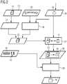
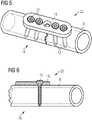
1 einen Patienten, an dem ein Implantat zu platzieren ist, mit Röntgensystem,2 ein Ablaufdiagramm des erfindungsgemäßen Verfahrens,3 3D-Bilddaten des gebrochenen Knochens des Patienten aus1 ,4 den Knochen aus3 mit virtuellem Implantat,5 den Knochen aus 4 mit virtuellen Schrauben,6 ein Schnittbild durch die 3D-Bilddaten aus5 ,7 ein Ablaufdiagramm fürden Matchingschritt aus 2 .
1 a patient on whom an implant is to be placed, with an X-ray system,2 a flowchart of the method according to the invention,3 3D image data of the patient's fractured bone1 ,4 the bone out3 with virtual implant,5 the bone out4 with virtual screws,6 a slice through the 3D image data5 ,7 a flowchart for the matchingstep 2 .
Im Rahmen eines chirurgischen Eingriffs am Patienten 2 soll nun das Implantat 10 am Einsatzort 8 im Patienten 2 platziert werden. Hierzu sollen Planungsdaten 18 erzeugt werden, die mit der Platzierung des Implantats 10 im Patienten 2 korreliert sind.As part of a surgical intervention on the
Ist die Dislokation der Fragmente des Knochens 6 genügend klein, hier kleiner als 1 mm, werden die 3D-Bilddaten 22 direkt weiter verarbeitet. Für den alternativen Fall einer größeren Dislokation wird in einem Reponierschritt 24 an den 3D-Bilddaten 22 eine virtuelle Reponierung der Fragmente des Knochens 6 durchgeführt, bis eine akzeptable Dislokation von wiederum kleiner 1 mm erreicht ist. Abschließend stehen jeweils die 3D-Bilddaten 22 - im Original oder reponiert - für das weitere Verfahren zur Verfügung.If the dislocation of the fragments of the
Erfindungsgemäß werden die 3D-Bilddaten 22 künstlich, d.h. nicht durch eine tatsächliche Aufnahme am Patienten 2, generiert. Ausgehend von einem statistischen 3D-Modell 26 des Knochens 6 wird dieses in einem Anpassungsschritt 28 - je nach den tatsächlichen Gegebenheiten im Patienten 2, also gemäß der 2D-Bilddaten 16 - individualisiert. Es wird also ein individuelles Modell des Knochens 6 angefertigt. Dieses wird dann in Form der 3D-Bilddaten 22 zur Verfügung gestellt, so dass schließlich modellbasierte, individualisierte statistische 3D-Bilddaten 22 erzeugt werden, um für das weitere Verfahren zu dienen.According to the invention, the
In einem weiteren Aufnahmeschritt 30 werden nun mit Hilfe des Bildgebungssystems 14 2D-Bilddaten 16 vom Patienten 2 erzeugt. Im o.g. Fall erfolgt dieser Schritt vorab, um die 2D-Bilddaten 16 im Anpassungsschritt 28 benutzen zu können, und so das 3D-Modell 26 auf den speziellen Patienten 2 bzw. Knochen 6 zu individualisieren.In a
In einer ersten Verfahrensvariante werden die 2D-Bilddaten 16 nur vom Knochen 6, d.h. ohne Implantat 10 aufgenommen.In a first variant of the method, the
In einem Matching-Schritt 32 erfolgt nun ein 2D/3D-Matching zwischen den 3D-Bilddaten 22 und den 2D-Bilddaten 16. Insbesondere werden hierbei die 3D-Bilddaten 22 einem Koordinatensystem 34 des Bildgebungssystems 14 ortsrichtig zugeordnet. So entstehen synthetische 3D-Daten 36, welche die zueinander ortsrichtig zugeordneten 3D-Bilddaten 22 und 2D-Bilddaten 16 beinhalten.In a matching
Im Rahmen eines virtuellen Einpassschrittes 38 werden nun virtuelle Modelle des Implantats 10 bzw. der Befestigungsmittel 12 in die 3D-Bilddaten 22 und damit auch in die synthetischen 3D-Daten 36 und in die 2D-Bilddaten 16 eingepasst.As part of a virtual
Hieraus können dann die Planungsdaten 18 ermittelt werden. Z.B. sind die Planungsdaten 18 die synthetischen 3D-Daten 36 mit eingepassten Modellen von Implantat 10 und Befestigungsmitteln 12 in bildhafter Form. Die Planungsdaten 18 sind dann 3D-Planungsbilddaten. Sie zeigen die Implantatlage in der aktuellen Aufnahmeposition der 2D-Bilddaten 16 und in 3D zusammen mit den Anteilen aus den 3D-Bilddaten 22.The
Die Planungsdaten 18 können aber auch alternativ oder zusätzlich konkrete Daten, z.B. Typen, Längen, Positionen, Winkel, Einschraubwinkel, des Implantats 10 oder der Befestigungsmittel sein, die aus deren virtuellen Modellen und deren korrekten Einpassung ermittelt werden.Alternatively or additionally, the
Das Wichtige im Kern des Verfahrens ist hierbei die zuverlässige 3D-Information, die in Verbindung mit den 3D-Bilddaten 22 gewonnen wird, und die die relative Position des Implantats 10 bzw. der Befestigungsmittel 12 zum Knochen 6 beschreibt. So ist z.B. sicherstellt, dass keine Schraubenspitze unzulässig über den Knochen 6 hinausragt.What is important at the core of the method is the reliable 3D information that is obtained in connection with the
In verschiedenen alternativen Ausführungsformen liegen die Aufnahmezeitpunkte der 2D-Bilddaten 16 und der 3D-Bilddaten 22 präoperativ oder intraoperativ.In various alternative embodiments, the recording times of the
In weiteren verschiedenen Ausführungsformen enthalten die 2D-Bilddaten 16 Abbildungen des Knochens 6 zusammen mit dem real bereits am Patienten 10 vorplatzierten Implantat 10 oder auch nur Abbildungen des Knochens 6 alleine, d.h. ohne eine Abbildung des Implantats 10.In other different embodiments, the
In einer weiteren alternativen Ausführungsform sind die 2D-Bilddaten 16 eines von mehreren 2D-Bildern, die zur Erzeugung der 3D-Bildaten 22 aufgenommen werden, also ein Teil des 3D-Bilddatensatzes.In a further alternative embodiment, the
BezugszeichenlisteReference List
- 22
- Patientpatient
- 44
- Beinleg
- 66
- KnochenBone
- 88th
- Einsatzortlocation
- 1010
- Implantatimplant
- 1212
- Befestigungsmittelfasteners
- 1414
- Bildgebungssystemimaging system
- 1616
- 2D-Bilddaten2D image data
- 1818
- Planungsdatenplanning data
- 2020
- Aufnahmeschrittrecording step
- 2222
- 3D-Bilddaten3D image data
- 2424
- Reponierschrittreduction step
- 2626
- 3D-Modell3D model
- 2828
- Anpassungsschrittadjustment step
- 3030
- Aufnahmeschrittrecording step
- 3232
- Matchingschrittmatching step
- 3434
- Koordinatensystemcoordinate system
- 3636
- 3D-Daten3D data
- 3838
- Einpassschrittfitting step
- 4040
- Anfangswerteinitial values
- 4242
- Projektionsparameterprojection parameters
- 4444
- Abbildungsschrittmapping step
- 4646
- synthetische 2D-Projektionsdatensynthetic 2D projection data
- 4848
- Vergleichsschrittcomparison step
- 5050
- Variationsschrittvariation step
Claims (7)
Translated fromGermanPriority Applications (1)
| Application Number | Priority Date | Filing Date | Title |
|---|---|---|---|
| DE102011083063.4ADE102011083063B4 (en) | 2011-09-20 | 2011-09-20 | Method for generating planning data for an implant |
Applications Claiming Priority (1)
| Application Number | Priority Date | Filing Date | Title |
|---|---|---|---|
| DE102011083063.4ADE102011083063B4 (en) | 2011-09-20 | 2011-09-20 | Method for generating planning data for an implant |
Publications (2)
| Publication Number | Publication Date |
|---|---|
| DE102011083063A1 DE102011083063A1 (en) | 2013-03-21 |
| DE102011083063B4true DE102011083063B4 (en) | 2022-09-01 |
Family
ID=47751100
Family Applications (1)
| Application Number | Title | Priority Date | Filing Date |
|---|---|---|---|
| DE102011083063.4AActiveDE102011083063B4 (en) | 2011-09-20 | 2011-09-20 | Method for generating planning data for an implant |
Country Status (1)
| Country | Link |
|---|---|
| DE (1) | DE102011083063B4 (en) |
Families Citing this family (2)
| Publication number | Priority date | Publication date | Assignee | Title |
|---|---|---|---|---|
| DE102013204552B4 (en) | 2013-03-15 | 2023-09-21 | Siemens Healthcare Gmbh | Method for artifact-free reproduction of metal parts in three-dimensionally reconstructed images |
| DE102020117808A1 (en) | 2020-07-06 | 2022-01-13 | Adrian Kilian | Implant, guide and procedure |
Citations (6)
| Publication number | Priority date | Publication date | Assignee | Title |
|---|---|---|---|---|
| US20050085714A1 (en) | 2003-10-16 | 2005-04-21 | Foley Kevin T. | Method and apparatus for surgical navigation of a multiple piece construct for implantation |
| DE60032475T2 (en) | 1999-03-23 | 2007-09-27 | Medtronic Surgical Navigation Technologies, Louisville | NAVIGATION GUIDANCE ON COMPUTER-BASED FLUOROSCOPIC IMAGING |
| US20080089566A1 (en) | 2006-10-11 | 2008-04-17 | General Electric Company | Systems and methods for implant virtual review |
| US20080119724A1 (en) | 2006-11-17 | 2008-05-22 | General Electric Company | Systems and methods for intraoperative implant placement analysis |
| US20090088830A1 (en) | 2007-02-15 | 2009-04-02 | Siemens Corporate Research, Inc. | System and method for intraoperative guidance of stent placement during endovascular interventions |
| DE102009037251A1 (en) | 2009-08-12 | 2011-02-17 | Siemens Aktiengesellschaft | Method for generating three-dimensional images of body by radioscopy, involves generating two-dimensional image of body from different viewing directions by radioscopy |
- 2011
- 2011-09-20DEDE102011083063.4Apatent/DE102011083063B4/enactiveActive
Patent Citations (6)
| Publication number | Priority date | Publication date | Assignee | Title |
|---|---|---|---|---|
| DE60032475T2 (en) | 1999-03-23 | 2007-09-27 | Medtronic Surgical Navigation Technologies, Louisville | NAVIGATION GUIDANCE ON COMPUTER-BASED FLUOROSCOPIC IMAGING |
| US20050085714A1 (en) | 2003-10-16 | 2005-04-21 | Foley Kevin T. | Method and apparatus for surgical navigation of a multiple piece construct for implantation |
| US20080089566A1 (en) | 2006-10-11 | 2008-04-17 | General Electric Company | Systems and methods for implant virtual review |
| US20080119724A1 (en) | 2006-11-17 | 2008-05-22 | General Electric Company | Systems and methods for intraoperative implant placement analysis |
| US20090088830A1 (en) | 2007-02-15 | 2009-04-02 | Siemens Corporate Research, Inc. | System and method for intraoperative guidance of stent placement during endovascular interventions |
| DE102009037251A1 (en) | 2009-08-12 | 2011-02-17 | Siemens Aktiengesellschaft | Method for generating three-dimensional images of body by radioscopy, involves generating two-dimensional image of body from different viewing directions by radioscopy |
Non-Patent Citations (1)
| Title |
|---|
| PENNEY, G. P: Registration of Tomographic Images to X-ray Projections for Use in Image Guided Interventions. PhD Thesis, King’s College London, 1999, S. 1-203. |
Also Published As
| Publication number | Publication date |
|---|---|
| DE102011083063A1 (en) | 2013-03-21 |
Similar Documents
| Publication | Publication Date | Title |
|---|---|---|
| EP1348393A1 (en) | Medical navigation or pre-operative treatment planning supported by generic patient data | |
| EP1894538B1 (en) | Method and device for determining the position of pelvic planes | |
| WO2014008613A1 (en) | Method for generating a graphical 3d computer model of at least one anatomical structure in a selectable pre-, intra-, or postoperative status | |
| WO2011047960A1 (en) | Method for determining the projection geometry of an x-ray apparatus | |
| DE10202091A1 (en) | Determination of a coordinate transformation between a coordinate system belonging to a surgical navigation system and a coordinate system belonging to an X-ray imaging system by use of appropriate marker sets | |
| DE102010020284A1 (en) | Determination of 3D positions and orientations of surgical objects from 2D X-ray images | |
| EP2997540B1 (en) | Intraoperative image registration using fiducial marks | |
| WO2002062250A1 (en) | Device and method for intraoperative navigation | |
| EP1153572A1 (en) | Method of registering of patient data of an imaging method for navigation supported surgical operations by means of X-ray image correspondance | |
| DE3838011A1 (en) | METHOD AND DEVICE FOR GENERATING IMAGES OF THE ANATOMY | |
| DE102010061777B4 (en) | Method for determining a parameter of a fixing element for an implant to be fixed to a bone | |
| DE102005023194A1 (en) | Method for expanding the display area of 2D image recordings of an object area | |
| DE102013204552B4 (en) | Method for artifact-free reproduction of metal parts in three-dimensionally reconstructed images | |
| EP1348394B1 (en) | Planning or navigation assistance by generic obtained patient data with two-dimensional adaptation | |
| EP1629789B1 (en) | Fluoroscopic image verification | |
| DE102013207463A1 (en) | Control for positioning an endoprosthesis | |
| EP1795230A1 (en) | Medical irradiation device | |
| DE102011083063B4 (en) | Method for generating planning data for an implant | |
| DE102013208285B4 (en) | Method and device for assisting in the treatment of bone fractures | |
| DE102021214741B3 (en) | Method for generating synthetic X-ray images, control unit and computer program | |
| DE10235795B4 (en) | Medical device | |
| DE102008054298B4 (en) | Method and device for 3D visualization of an intervention path of a medical instrument, a medical instrument and / or a specific tissue structure of a patient | |
| DE102009034669B4 (en) | Method for generating a fluoroscopic image of a limb to be repositioned | |
| DE102012217942A1 (en) | Medical instrument, medical system and method for displaying the position of a placemark | |
| EP2584960A2 (en) | Method for displaying stored high-resolution diagnostic 3-d image data and 2-d realtime sectional image data simultaneously, continuously, and in parallel during a medical intervention of a patient and arrangement for carrying out said method |
Legal Events
| Date | Code | Title | Description |
|---|---|---|---|
| R012 | Request for examination validly filed | ||
| R016 | Response to examination communication | ||
| R016 | Response to examination communication | ||
| R081 | Change of applicant/patentee | Owner name:SIEMENS HEALTHCARE GMBH, DE Free format text:FORMER OWNER: SIEMENS AKTIENGESELLSCHAFT, 80333 MUENCHEN, DE | |
| R016 | Response to examination communication | ||
| R018 | Grant decision by examination section/examining division | ||
| R020 | Patent grant now final | ||
| R081 | Change of applicant/patentee | Owner name:SIEMENS HEALTHINEERS AG, DE Free format text:FORMER OWNER: SIEMENS HEALTHCARE GMBH, MUENCHEN, DE |