DE102011082102A1 - Electrode arrangement and electronic gripping instrument - Google Patents
Electrode arrangement and electronic gripping instrumentDownload PDFInfo
- Publication number
- DE102011082102A1 DE102011082102A1DE102011082102ADE102011082102ADE102011082102A1DE 102011082102 A1DE102011082102 A1DE 102011082102A1DE 102011082102 ADE102011082102 ADE 102011082102ADE 102011082102 ADE102011082102 ADE 102011082102ADE 102011082102 A1DE102011082102 A1DE 102011082102A1
- Authority
- DE
- Germany
- Prior art keywords
- electrode
- heating element
- insulator
- electrode arrangement
- tissue
- Prior art date
- Legal status (The legal status is an assumption and is not a legal conclusion. Google has not performed a legal analysis and makes no representation as to the accuracy of the status listed.)
- Withdrawn
Links
- 238000010438heat treatmentMethods0.000claimsabstractdescription75
- 239000012212insulatorSubstances0.000claimsabstractdescription56
- 239000004033plasticSubstances0.000claimsdescription8
- 229920003023plasticPolymers0.000claimsdescription8
- 239000000919ceramicSubstances0.000claimsdescription5
- 239000011521glassSubstances0.000claimsdescription3
- 239000010703siliconSubstances0.000claimsdescription3
- 229910052710siliconInorganic materials0.000claimsdescription3
- 239000004642PolyimideSubstances0.000claimsdescription2
- 229920002457flexible plasticPolymers0.000claimsdescription2
- 229920001721polyimidePolymers0.000claimsdescription2
- 230000004927fusionEffects0.000description9
- 239000000463materialSubstances0.000description5
- 238000000576coating methodMethods0.000description3
- 238000013461designMethods0.000description3
- 239000011248coating agentSubstances0.000description2
- 239000003822epoxy resinSubstances0.000description2
- 238000004519manufacturing processMethods0.000description2
- 238000012986modificationMethods0.000description2
- 230000004048modificationEffects0.000description2
- 230000003287optical effectEffects0.000description2
- 229920000647polyepoxidePolymers0.000description2
- BUHVIAUBTBOHAG-FOYDDCNASA-N(2r,3r,4s,5r)-2-[6-[[2-(3,5-dimethoxyphenyl)-2-(2-methylphenyl)ethyl]amino]purin-9-yl]-5-(hydroxymethyl)oxolane-3,4-diolChemical compoundCOC1=CC(OC)=CC(C(CNC=2C=3N=CN(C=3N=CN=2)[C@H]2[C@@H]([C@H](O)[C@@H](CO)O2)O)C=2C(=CC=CC=2)C)=C1BUHVIAUBTBOHAG-FOYDDCNASA-N0.000description1
- 229910001030Iron–nickel alloyInorganic materials0.000description1
- GTDPSWPPOUPBNX-UHFFFAOYSA-Nac1mqpvaChemical compoundCC12C(=O)OC(=O)C1(C)C1(C)C2(C)C(=O)OC1=OGTDPSWPPOUPBNX-UHFFFAOYSA-N0.000description1
- 239000000853adhesiveSubstances0.000description1
- 230000001070adhesive effectEffects0.000description1
- 150000004984aromatic diaminesChemical class0.000description1
- 238000003491arrayMethods0.000description1
- 125000003118aryl groupChemical group0.000description1
- 230000000712assemblyEffects0.000description1
- 238000000429assemblyMethods0.000description1
- 239000000560biocompatible materialSubstances0.000description1
- 239000008280bloodSubstances0.000description1
- 210000004369bloodAnatomy0.000description1
- 238000009529body temperature measurementMethods0.000description1
- 230000015271coagulationEffects0.000description1
- 238000005345coagulationMethods0.000description1
- 239000004020conductorSubstances0.000description1
- 238000005520cutting processMethods0.000description1
- 238000009826distributionMethods0.000description1
- 230000000694effectsEffects0.000description1
- 230000020169heat generationEffects0.000description1
- 238000002955isolationMethods0.000description1
- 238000010030laminatingMethods0.000description1
- 229910052751metalInorganic materials0.000description1
- 239000002184metalSubstances0.000description1
- 150000002739metalsChemical class0.000description1
- 239000000615nonconductorSubstances0.000description1
- 229920003223poly(pyromellitimide-1,4-diphenyl ether)Polymers0.000description1
- 238000006068polycondensation reactionMethods0.000description1
- 238000007639printingMethods0.000description1
- 238000004544sputter depositionMethods0.000description1
- 239000010935stainless steelSubstances0.000description1
- 229910001220stainless steelInorganic materials0.000description1
- 239000000126substanceSubstances0.000description1
- 230000007704transitionEffects0.000description1
- 210000003462veinAnatomy0.000description1
Images


Classifications
- A—HUMAN NECESSITIES
- A61—MEDICAL OR VETERINARY SCIENCE; HYGIENE
- A61B—DIAGNOSIS; SURGERY; IDENTIFICATION
- A61B18/00—Surgical instruments, devices or methods for transferring non-mechanical forms of energy to or from the body
- A61B18/04—Surgical instruments, devices or methods for transferring non-mechanical forms of energy to or from the body by heating
- A61B18/08—Surgical instruments, devices or methods for transferring non-mechanical forms of energy to or from the body by heating by means of electrically-heated probes
- A61B18/082—Probes or electrodes therefor
- A61B18/085—Forceps, scissors
- A—HUMAN NECESSITIES
- A61—MEDICAL OR VETERINARY SCIENCE; HYGIENE
- A61B—DIAGNOSIS; SURGERY; IDENTIFICATION
- A61B18/00—Surgical instruments, devices or methods for transferring non-mechanical forms of energy to or from the body
- A61B18/04—Surgical instruments, devices or methods for transferring non-mechanical forms of energy to or from the body by heating
- A61B18/12—Surgical instruments, devices or methods for transferring non-mechanical forms of energy to or from the body by heating by passing a current through the tissue to be heated, e.g. high-frequency current
- A61B18/14—Probes or electrodes therefor
- A61B18/1442—Probes having pivoting end effectors, e.g. forceps
- A—HUMAN NECESSITIES
- A61—MEDICAL OR VETERINARY SCIENCE; HYGIENE
- A61B—DIAGNOSIS; SURGERY; IDENTIFICATION
- A61B18/00—Surgical instruments, devices or methods for transferring non-mechanical forms of energy to or from the body
- A61B2018/00053—Mechanical features of the instrument of device
- A61B2018/00059—Material properties
- A61B2018/00071—Electrical conductivity
- A61B2018/00083—Electrical conductivity low, i.e. electrically insulating
- A—HUMAN NECESSITIES
- A61—MEDICAL OR VETERINARY SCIENCE; HYGIENE
- A61B—DIAGNOSIS; SURGERY; IDENTIFICATION
- A61B18/00—Surgical instruments, devices or methods for transferring non-mechanical forms of energy to or from the body
- A61B2018/00053—Mechanical features of the instrument of device
- A61B2018/00059—Material properties
- A61B2018/00089—Thermal conductivity
- A61B2018/00095—Thermal conductivity high, i.e. heat conducting
- A—HUMAN NECESSITIES
- A61—MEDICAL OR VETERINARY SCIENCE; HYGIENE
- A61B—DIAGNOSIS; SURGERY; IDENTIFICATION
- A61B18/00—Surgical instruments, devices or methods for transferring non-mechanical forms of energy to or from the body
- A61B2018/00571—Surgical instruments, devices or methods for transferring non-mechanical forms of energy to or from the body for achieving a particular surgical effect
- A61B2018/0063—Sealing
- A—HUMAN NECESSITIES
- A61—MEDICAL OR VETERINARY SCIENCE; HYGIENE
- A61B—DIAGNOSIS; SURGERY; IDENTIFICATION
- A61B18/00—Surgical instruments, devices or methods for transferring non-mechanical forms of energy to or from the body
- A61B2018/00636—Sensing and controlling the application of energy
- A61B2018/00773—Sensed parameters
- A61B2018/00791—Temperature
- A61B2018/00797—Temperature measured by multiple temperature sensors
- A—HUMAN NECESSITIES
- A61—MEDICAL OR VETERINARY SCIENCE; HYGIENE
- A61B—DIAGNOSIS; SURGERY; IDENTIFICATION
- A61B18/00—Surgical instruments, devices or methods for transferring non-mechanical forms of energy to or from the body
- A61B2018/00994—Surgical instruments, devices or methods for transferring non-mechanical forms of energy to or from the body combining two or more different kinds of non-mechanical energy or combining one or more non-mechanical energies with ultrasound
Landscapes
- Health & Medical Sciences (AREA)
- Surgery (AREA)
- Engineering & Computer Science (AREA)
- Life Sciences & Earth Sciences (AREA)
- Biomedical Technology (AREA)
- Molecular Biology (AREA)
- Nuclear Medicine, Radiotherapy & Molecular Imaging (AREA)
- Plasma & Fusion (AREA)
- Physics & Mathematics (AREA)
- Heart & Thoracic Surgery (AREA)
- Medical Informatics (AREA)
- Otolaryngology (AREA)
- Animal Behavior & Ethology (AREA)
- General Health & Medical Sciences (AREA)
- Public Health (AREA)
- Veterinary Medicine (AREA)
- Surgical Instruments (AREA)
- Resistance Heating (AREA)
Abstract
Translated fromGermanDescription
Translated fromGermanDie Erfindung betrifft eine Elektrodenanordnung für ein elektrochirurgisches Greifinstrument mit einer Elektrode, einem Heizelement und einem zwischen der Elektrode und dem Heizelement angeordneten, diese voneinander isolierenden Isolator. Des Weiteren betrifft die Erfindung ein elektrochirurgisches Greifinstrument mit einem Maulteil.The invention relates to an electrode assembly for an electrosurgical gripping instrument comprising an electrode, a heating element and an insulator arranged between the electrode and the heating element and insulating them from each other. Furthermore, the invention relates to an electrosurgical gripping instrument with a jaw part.
Elektrochirurgische Greifinstrumente werden verwendet, um Gewebe, beispielsweise blutführende Adern, zu koagulieren und/oder zu durchschneiden. Außerdem werden sie verwendet, um zwei lose Gewebeteile zu fusionieren, d. h. dauerhaft zu verbinden, wodurch eine Naht überflüssig wird. Hierzu weisen elektrochirurgische Greifinstrumente typischerweise zwei Maulteile auf, zwischen welchen das zu koagulierende, zu durchschneidende oder zu fusionierende Gewebe gegriffen wird. Auf den Maulteilen sind typischerweise Elektrodenanordnungen aufgebracht, durch welche eine hochfrequente (HF) Spannung an das Gewebe angelegt werden kann.Electrosurgical gripping instruments are used to coagulate and / or cut tissue, such as blood-bearing veins. In addition, they are used to fuse two loose pieces of tissue, i. H. permanently connect, making a seam superfluous. For this purpose, electrosurgical gripping instruments typically have two jaws between which the tissue to be coagulated, cut or fused is gripped. Electrode arrays are typically applied to the jaws through which a high frequency (RF) voltage can be applied to the tissue.
Bei bestimmten Anwendungen, wie z. B. beim Fusionieren, kann es von Vorteil sein, zusätzlich zu der Elektrode auch noch ein Heizelement im Instrument zu haben. So kann z. B. zunächst mittels HF-Energie fusioniert und anschließend, wenn der erhöhte Gewebewiderstand die Fusion mittels HF stoppt, über die Wärmeenergie des Heizelements weiter fusioniert werden. Die Elektroden werden beheizt, um einen vom Stromfluss unabhängigen Energieeintrag vorzusehen. Hierzu können Heizelemente zum Beheizen der Elektrode vorgesehen sein. Da sowohl durch die Elektrode wie auch durch die Heizelemente Strom fließt, sind diese voneinander elektrisch zu isolieren. Typischerweise erfolgt dies mittels eines keramischen Isolators. Allerdings besteht bei keramischen Isolatoren die Gefahr, dass sie bei dem hohen Druck, welcher beim Koagulieren und Schneiden auftritt, brechen und somit ihre Eigenschaft als Isolator verlieren.For certain applications, such as As in fusion, it may be advantageous to have in addition to the electrode also has a heating element in the instrument. So z. B. initially fused by means of RF energy and then, when the increased tissue resistance stops the fusion by means of HF, are further fused via the heat energy of the heating element. The electrodes are heated to provide an energy input independent of the current flow. For this purpose, heating elements can be provided for heating the electrode. Since current flows through both the electrode and the heating elements, they are to be electrically insulated from one another. Typically, this is done by means of a ceramic insulator. However, ceramic insulators are in danger of breaking at the high pressure encountered during coagulation and cutting, thus losing their insulator character.
Das Dokument
Das Dokument
Ein Heizelement ist außerdem in dem Dokument
Es ist wünschenswert, die Zuverlässigkeit der Elektrodenanordnung auch zu erhöhen.It is desirable to increase the reliability of the electrode assembly as well.
Dies wird erfindungsgemäß durch eine Elektrodenanordnung gemäß Anspruch 1 sowie durch ein elektrochirurgisches Greifinstrument gemäß Anspruch 14 erreicht. Vorteilhafte Ausgestaltungen können den jeweiligen Unteransprüchen entnommen werden.This is inventively achieved by an electrode assembly according to claim 1 and by an electrosurgical gripping instrument according to claim 14. Advantageous embodiments can be taken from the respective subclaims.
Gemäß einem ersten Aspekt betrifft die Erfindung eine Elektrodenanordnung für ein elektrochirurgisches Greifinstrument. Diese weist eine Elektrode, ein Heizelement und einen zwischen der Elektrode und dem Heizelement angeordneten, diese voneinander isolierenden Isolator auf. Der Isolator ist dabei biegeweich.According to a first aspect, the invention relates to an electrode assembly for an electrosurgical gripping instrument. It has an electrode, a heating element and an insulator arranged between the electrode and the heating element and insulating them from each other. The insulator is bendable.
Die Erfinder haben erkannt, dass die Zuverlässigkeit der Elektrodenanordnung dadurch beeinträchtigt sein kann, dass bei Ausübung eines hohen Drucks auf ein Gewebe sich ein Maulteil eines Greifinstruments, an welchem die Elektrodenanordnung angebracht ist, verbiegen kann. Hierbei wirkt auf den Isolator eine hohe Zugbelastung. Die Elektrodenanordnung gemäß dem ersten Aspekt der Erfindung ermöglicht, dass der Isolator bei einer solchen Biegung nicht bricht.The inventors have recognized that the reliability of the electrode assembly may be affected by the fact that when a high pressure is applied to a tissue, a jaw portion of a grasping instrument to which the electrode assembly is attached may bend. Here, a high tensile load acts on the insulator. The electrode assembly according to the first aspect of the invention allows the insulator not to break in such a bend.
Unter einem Isolator im Sinne dieser Anmeldung wird grundsätzlich ein elektrischer Isolator verstanden, also ein Material mit einem ausreichend hohen elektrischen Widerstand zur Verhinderung eines Stromflusses. Bevorzugt weist der Isolator eine gute Wärmeleitfähigkeit auf.Under an insulator in the sense of this application is basically an electrical insulator understood, ie a material with a sufficiently high electrical resistance to prevent current flow. Preferably, the insulator has a good thermal conductivity.
Eine Elektrode besteht typischerweise aus einem leitfähigen Material, und insbesondere aus einem biokompatiblen Material. Beispielsweise bieten sich hier verschiedene Metalle an. Bevorzugt ist die Elektrode flächig, wodurch eine ebene, gleichmäßige Kontaktfläche zum Gewebe erreicht wird.An electrode is typically made of a conductive material, and more particularly of a biocompatible material. For example, different metals are available here. Preferably, the electrode is flat, whereby a flat, uniform contact surface to the tissue is achieved.
Typischerweise ist die Elektrode steif, insbesondere erheblich steifer als der Isolator. Die Elektrode stellt somit eine ebene Kontaktfläche zur Verfügung, die sich jedoch aufgrund der bei der Anwendung auftretenden Kräfte mehr oder weniger stark biegen kann. Alternativ kann die Elektrode auch leicht verformbar, beispielsweise biegeweich, sein. In diesem Fall kann sie sich Unebenheiten des Gewebes anpassen.Typically, the electrode is stiff, in particular significantly stiffer than the insulator. The electrode thus provides a flat contact surface which, however, can bend more or less due to the forces occurring during application. Alternatively, the electrode may also be easily deformable, for example bendable. In this case, it can adapt to unevenness of the tissue.
Die Elektrode kann als Schicht auf der dem Heizelement abgewandten Seite des Isolators ausgebildet sein. Beispielsweise kann dies durch ein Beschichtungsverfahren erreicht werden, bei welchem der Isolator mit der Elektrode beschichtet wird. In diesem Fall wäre die Elektrode eine Beschichtung des Isolators.The electrode may be formed as a layer on the side facing away from the heating element of the insulator. For example, this can be achieved by a coating method in which the insulator is coated with the electrode. In this case, the electrode would be a coating of the insulator.
Die umgekehrte Anordnung ist jedoch ebenfalls vorteilhaft. Dabei wird der Isolator auf die Elektrode beschichtet. Durch die Beschichtung werden Luftblasen zwischen Elektrode und Isolator vermieden. Die Elektrode bildet hier das tragende Element der Elektrodenanordnung.However, the reverse arrangement is also advantageous. The insulator is coated on the electrode. The coating creates air bubbles between the electrode and the insulator avoided. The electrode forms the supporting element of the electrode arrangement here.
Das Heizelement besteht typischerweise aus einem Material, welches über einen geeigneten Widerstand verfügt, so dass ein durchfließender Strom zur Erwärmung führt. Die entstandene Wärme wird über den Isolator an die Elektrode abgegeben. Von der Elektrode wird die Wärme an das Gewebe abgegeben. Beispielsweise kann das Heizelement ganz oder teilweise aus einer Eisen-Nickel-Legierung bestehen.The heating element typically consists of a material which has a suitable resistance, so that a current flowing through it leads to heating. The resulting heat is released via the insulator to the electrode. The electrode transfers the heat to the tissue. For example, the heating element may consist wholly or partly of an iron-nickel alloy.
Das Heizelement ist bevorzugt flächig ausgebildet. Es kann beispielsweise als Schicht auf dem Isolator ausgebildet sein. Besonders bevorzugt überdeckt das Heizelement einen Großteil einer Fläche des Isolators, beispielsweise mehr als 80% einer Fläche des Isolators. Der Isolator überdeckt wiederum bevorzugt mindestens etwa 90% der Fläche der Elektrode. Damit wird eine besonders gleichmäßige Erzeugung und Verteilung von Wärme erreicht.The heating element is preferably flat. It may be formed for example as a layer on the insulator. Particularly preferably, the heating element covers a major part of a surface of the insulator, for example more than 80% of a surface of the insulator. Again, the insulator preferably covers at least about 90% of the area of the electrode. This achieves a particularly uniform generation and distribution of heat.
Es sei erwähnt, dass die erfindungsgemäß biegeweiche Ausführung des Isolators auch bei Verwendung eines flächigen Heizelements die Zuverlässigkeit des Isolators sicherstellt. Der Isolator kann auch aus dünnen Schichten aus Keramik, Glas oder Silizium bestehen, die so auch flexibel sind. Bevorzugt beträgt die Materialdicke dann wenige zehntel Millimeter. Das Heizelement ist bevorzugt wenigstens doppelt, besonders bevorzugt wenigstens viermal so dick wie der Isolator ausgebildet.It should be noted that the inventive flexible design of the insulator ensures the reliability of the insulator even when using a flat heating element. The insulator can also consist of thin layers of ceramic, glass or silicon, which are also flexible. The material thickness is then preferably a few tenths of a millimeter. The heating element is preferably formed at least twice, more preferably at least four times as thick as the insulator.
Die Elektrodenanordnung weist bevorzugt eine oder mehrere Ausnehmungen für Temperatursensoren auf. Mit derartigen Temperatursensoren kann die Temperatur der Elektrode oder des behandelten Körpergewebes überwacht werden. Es kann sich hierbei um optische Temperatursensoren handeln. Die Ausnehmungen können beispielsweise in Form von Löchern in einem flächig ausgebildeten Heizelement ausgestaltet sein.The electrode arrangement preferably has one or more recesses for temperature sensors. With such temperature sensors, the temperature of the electrode or the treated body tissue can be monitored. These may be optical temperature sensors. The recesses can be configured, for example, in the form of holes in a flat heating element.
Als eine Alternative zu einem flächigen Heizelement kann das Heizelement jedoch auch durch einen Heizdraht ausgebildet sein, welcher in geeigneter Weise auf dem Isolator verlegt ist. Beispielsweise kann der Heizdraht zumindest teilweise gefaltet oder wendelförmig verlegt sein. Damit kann ebenfalls eine gleichmäßige Wärmeerzeugung erreicht werden.However, as an alternative to a flat heating element, the heating element may also be formed by a heating wire, which is laid in a suitable manner on the insulator. For example, the heating wire may be at least partially folded or helically laid. Thus, a uniform heat generation can also be achieved.
Der Isolator besteht bevorzugt ganz oder teilweise aus einem flexiblen Kunststoff. Besonders eignet sich hierfür ein Polyimid. Ein geeigneter Kunststoff wird beispielsweise durch Polykondensation eines aromatischen Dianhydrids und eines aromatischen Diamins hergestellt. Ein besonders geeigneter Kunststoff ist beispielsweise Poly(
Bevorzugt ist der Isolator flächig ausgebildet. Gemäß einer bevorzugten Ausführungsform ist der Isolator eine Folie aus isolierendem, biegeweichem Kunststoff, auf welche das Heizelement sowie Zuleitungen zum Heizelement aufgebracht sind. Durch die Verwendung einer Folie wird eine besonders einfach herzustellende Ausführung erreicht. Das Heizelement kann, nachdem es auf die Folie aufgebracht wurde, gemeinsam mit der Folie verarbeitet werden.Preferably, the insulator is formed flat. According to a preferred embodiment, the insulator is a film of insulating, pliable plastic, to which the heating element and supply lines are applied to the heating element. By using a film, a particularly easy to manufacture design is achieved. The heating element, after it has been applied to the film, can be processed together with the film.
Bevorzugt bilden das Heizelement, der Isolator und die Elektrode einen Schichtstapel. Dies ergibt eine besonders einfache und robuste Ausführung der Elektrodenanordnung.Preferably, the heating element, the insulator and the electrode form a layer stack. This results in a particularly simple and robust design of the electrode assembly.
Zuleitungen zum Heizelement dienen der Versorgung des Heizelements mit elektrischem Strom. Typischerweise benötigt ein Heizelement zwei Zuleitungen, um Strom durch das Heizelement zu leiten. Die Zuleitungen sind typischerweise mit elektrischen Anschlüssen verbunden, welche zu einer externen Strom- oder Spannungsquelle führen.Supply lines to the heating element serve to supply the heating element with electric current. Typically, a heating element requires two leads to conduct current through the heating element. The leads are typically connected to electrical terminals which lead to an external source of current or voltage.
Besonders bevorzugt ist es in diesem Fall, wenn die Folie und die Zuleitungen gemeinsam eine Kontaktfahne bilden, die seitlich von einer Fläche absteht, die von dem Heizelement eingenommen wird. Dies ermöglicht eine besonders einfache Herstellung, da die Kontaktfahne lediglich aus einer Ebene herausgebogen werden muss. Die Zuleitungen, welche Teil der Kontaktfahne sind, können bei dieser Ausführung mit elektrischen Anschlüssen verbunden werden, ohne dass ein unmittelbarer Kontakt zum Heizelement nötig wäre.It is particularly preferred in this case if the film and the leads together form a contact lug, which projects laterally from a surface which is occupied by the heating element. This allows a particularly simple production, since the contact lug must be bent out of one plane only. The leads, which are part of the contact lug, can be connected in this embodiment with electrical connections without direct contact with the heating element would be necessary.
Stellen, an welchen elektrische Anschlüsse mit Zuleitungen verbunden sind, beispielsweise solche Stellen auf einer Kontaktfahre, werden bevorzugt mit einem elektrisch isolierenden Kunststoff, besonders bevorzugt mit einem Epoxidharz abgedeckt. Hierfür eignet sich beispielsweise ein Kunststoff, welcher unter dem Handelnamen „Glob-Top“ vertrieben wird. Damit werden die abgedeckten Bereiche elektrisch isoliert und gegen mechanische Beschädigungen geschützt.Sites where electrical connections are connected to leads, such as those locations on a Kontaktfahre, are preferably covered with an electrically insulating plastic, more preferably with an epoxy resin. For this example, a plastic which is sold under the trade name "Glob-Top" is suitable. Thus, the covered areas are electrically insulated and protected against mechanical damage.
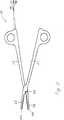
Gemäß einem zweiten Aspekt betrifft die Erfindung ein elektrochirurgisches Greifinstrument mit einem steifen Maulteil. Dabei trägt das Maulteil eine Elektrodenanordnung gemäß einer oder mehrerer Ausführungen des ersten Aspekts der Erfindung, wobei das Heizelement dem Maulteil und die Elektrode dem Gewebe zugewandt ist. Ein elektrochirurgisches Greifinstrument weist typischerweise mindestens ein Griffteil sowie zwei Maulteile auf. Mit dem Griffteil kann das elektrochirurgische Greifinstrument in der Hand gehalten werden. Unter einem Maulteil versteht man demgegenüber einen Teil des elektrochirurgischen Greifinstruments, welcher beim Greifen mit dem Gewebe in Kontakt kommt und dazu dient, einen Druck auf das Gewebe auszuüben.According to a second aspect, the invention relates to an electrosurgical gripping instrument with a rigid jaw part. In this case, the jaw part carries an electrode arrangement according to one or more embodiments of the first aspect of the invention, wherein the heating element faces the jaw part and the electrode faces the tissue. An electrosurgical gripping instrument typically has at least one handle part and two jaw parts. With the handle part, the electrosurgical gripping instrument can be held in the hand. Under a jaw part In contrast, one understands a part of the electrosurgical gripping instrument, which comes into contact with the tissue when gripping and serves to exert a pressure on the tissue.
In einer beispielhaften Ausführungsform ist ein Maulteil starr mit dem Griffteil verbunden, während ein weiteres Maulteil drehbar mit dem Griffteil verbunden ist. Durch Drehung des weiteren Maulteils relativ zum Griffteil und zum ersten Maulteil können die beiden Maulteile zusammen eine zangenartige Greifbewegung ausführen. Dabei ist das weitere Maulteil mit dem Griffteil und dem ersten Maulteil typischerweise mittels eines Gelenks verbunden, beispielsweise mittels eines Drehgelenks, eines Schraubgelenks oder Ähnlichem. In diesem Fall werden typischerweise die Teile des elektrochirurgischen Greifinstruments, welche sich bezüglich des Gelenks auf einer dem Griffteil abgewandten Seite befinden, als Maulteile bezeichnet.In an exemplary embodiment, one jaw member is rigidly connected to the handle member while another jaw member is rotatably connected to the handle member. By rotation of the other jaw part relative to the handle part and the first jaw part, the two jaw parts can perform together a pincer-like gripping movement. In this case, the further jaw part is typically connected to the grip part and the first jaw part by means of a joint, for example by means of a swivel joint, a screw joint or the like. In this case, typically the parts of the electrosurgical gripping instrument, which are located with respect to the joint on a side facing away from the handle part, referred to as jaw parts.
Alternativ kann das elektrochirurgische Greifinstrument jedoch auch zwei Griffteile aufweisen, wobei jeder Griffteil jeweils starr mit einem Maulteil verbunden ist, und wobei die beiden Griffteile sowie ihre jeweils zugehörigen Maulteile relativ zueinander um ein Gelenk drehbar angeordnet sind. Durch Zusammendrücken der beiden Griffteile kann in diesem Fall eine zangenartige Greifbewegung der beiden Maulteile erreicht werden.Alternatively, however, the electrosurgical gripping instrument can also have two gripping parts, each gripping part being respectively rigidly connected to a jaw part, and the two gripping parts and their respective associated jaw parts being arranged rotatable relative to one another around a joint. By squeezing the two handle parts, a pincer-like gripping movement of the two jaw parts can be achieved in this case.
Durch die Verwendung einer Elektrodenanordnung gemäß dem ersten Aspekt der Erfindung werden die Vorteile der Elektrodenanordnung für das elektrochirurgische Greifinstrument verwirklicht. Bevorzugt befindet sich dabei jeweils eine solche Elektrodenanordnung auf jedem der beiden Maulteile, wobei die beiden Elektrodenanordnungen aufeinander zu gewandt sind. Alternativ kann sich jedoch auch nur auf einem Maulteil des elektrochirurgischen Greifinstruments eine Elektrodenanordnung gemäß dem ersten Aspekt der Erfindung befinden.By using an electrode assembly according to the first aspect of the invention, the advantages of the electrode assembly for the electrosurgical gripping instrument are realized. In each case, such an electrode arrangement is preferably located on each of the two jaw parts, with the two electrode arrangements facing one another. Alternatively, however, an electrode arrangement according to the first aspect of the invention can also be located on only one jaw part of the electrosurgical gripping instrument.
Das Maulteil ist typischerweise steif ausgebildet, um den notwendigen Druck auf das Gewebe ausüben zu können. Dafür besteht das Maulteil typischerweise ganz oder teilweise aus Edelstahl oder anderem geeignetem Material.The jaw member is typically stiff to apply the necessary pressure to the tissue. For this, the jaw part is typically entirely or partially made of stainless steel or other suitable material.
Weitere Merkmale, Vorteile und Ausführungen der Erfindung werden mit Bezug auf die beigefügten Zeichnungen offensichtlich werden.Other features, advantages and embodiments of the invention will become apparent with reference to the accompanying drawings.
Wenn das erste Griffteil
Das erste Maulteil
Das elektrochirurgische Greifinstrument
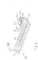
Geeignete Elektrodenanordnungen
Die Schichten des Stapels aus Elektrode, Isolator und Heizelement sind untereinander gut wärmeleitend verbunden. Dies kann beispielsweise durch einen geeigneten Kleber geschehen, oder auch durch laminieren, drucken oder sputtern.The layers of the stack of electrode, insulator and heating element are connected to each other with good thermal conductivity. This can be done for example by a suitable adhesive, or by laminating, printing or sputtering.
Des Weiteren sind auf dem Isolator
Der Isolator
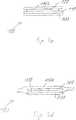
Die Elektrodenanordnung in
Eine Abwandlung des Ausführungsbeispiels von
Der Isolator
Bei einer Gewebefusion wird das erfindungsgemäße Greifinstrument
Nun wird zunächst das Zuführen von HF-Energie zu den Elektroden
Durch den HF-Strom beginnt das Gewebe auszutrocknen und der Gewebewiderstand steigt. Bevor zu wenig HF-Strom fließt, um Gewebe weiter zu erwärmen und zu fusionieren, werden die Heizelemente
Die HF-Elektroden
Die Heizelemente
Diese weist eine flächige Elektrode
Des Weiteren weisen das Heizelement
Zuleitungen und Anschlussleitungen sind in
ZITATE ENTHALTEN IN DER BESCHREIBUNG QUOTES INCLUDE IN THE DESCRIPTION
Diese Liste der vom Anmelder aufgeführten Dokumente wurde automatisiert erzeugt und ist ausschließlich zur besseren Information des Lesers aufgenommen. Die Liste ist nicht Bestandteil der deutschen Patent- bzw. Gebrauchsmusteranmeldung. Das DPMA übernimmt keinerlei Haftung für etwaige Fehler oder Auslassungen.This list of the documents listed by the applicant has been generated automatically and is included solely for the better information of the reader. The list is not part of the German patent or utility model application. The DPMA assumes no liability for any errors or omissions.
Zitierte PatentliteraturCited patent literature
- DE 202004010311 U1[0004]DE 202004010311 U1[0004]
- DE 112008000288 T5[0005]DE 112008000288 T5[0005]
- EP 2106762 A1[0006]EP 2106762 A1[0006]
Claims (14)
Translated fromGermanPriority Applications (5)
| Application Number | Priority Date | Filing Date | Title |
|---|---|---|---|
| DE102011082102ADE102011082102A1 (en) | 2011-09-02 | 2011-09-02 | Electrode arrangement and electronic gripping instrument |
| PCT/EP2012/066977WO2013030349A1 (en) | 2011-09-02 | 2012-08-31 | Electrode arrangement and electrosurgical gripping instrument |
| US14/342,429US9724152B2 (en) | 2011-09-02 | 2012-08-31 | Electrode arrangement and electrosurgical gripping instrument |
| JP2014527676AJP6116566B2 (en) | 2011-09-02 | 2012-08-31 | Electrode array and electrosurgical gripping device |
| CN201280042185.1ACN104023660B (en) | 2011-09-02 | 2012-08-31 | Electrode is arranged and electrosurgery grasps apparatus |
Applications Claiming Priority (1)
| Application Number | Priority Date | Filing Date | Title |
|---|---|---|---|
| DE102011082102ADE102011082102A1 (en) | 2011-09-02 | 2011-09-02 | Electrode arrangement and electronic gripping instrument |
Publications (1)
| Publication Number | Publication Date |
|---|---|
| DE102011082102A1true DE102011082102A1 (en) | 2013-03-07 |
Family
ID=46758770
Family Applications (1)
| Application Number | Title | Priority Date | Filing Date |
|---|---|---|---|
| DE102011082102AWithdrawnDE102011082102A1 (en) | 2011-09-02 | 2011-09-02 | Electrode arrangement and electronic gripping instrument |
Country Status (5)
| Country | Link |
|---|---|
| US (1) | US9724152B2 (en) |
| JP (1) | JP6116566B2 (en) |
| CN (1) | CN104023660B (en) |
| DE (1) | DE102011082102A1 (en) |
| WO (1) | WO2013030349A1 (en) |
Families Citing this family (159)
| Publication number | Priority date | Publication date | Assignee | Title |
|---|---|---|---|---|
| US11229472B2 (en) | 2001-06-12 | 2022-01-25 | Cilag Gmbh International | Modular battery powered handheld surgical instrument with multiple magnetic position sensors |
| US8182501B2 (en) | 2004-02-27 | 2012-05-22 | Ethicon Endo-Surgery, Inc. | Ultrasonic surgical shears and method for sealing a blood vessel using same |
| US20060079879A1 (en) | 2004-10-08 | 2006-04-13 | Faller Craig N | Actuation mechanism for use with an ultrasonic surgical instrument |
| US20070191713A1 (en) | 2005-10-14 | 2007-08-16 | Eichmann Stephen E | Ultrasonic device for cutting and coagulating |
| US7621930B2 (en) | 2006-01-20 | 2009-11-24 | Ethicon Endo-Surgery, Inc. | Ultrasound medical instrument having a medical ultrasonic blade |
| US8142461B2 (en) | 2007-03-22 | 2012-03-27 | Ethicon Endo-Surgery, Inc. | Surgical instruments |
| US8057498B2 (en) | 2007-11-30 | 2011-11-15 | Ethicon Endo-Surgery, Inc. | Ultrasonic surgical instrument blades |
| US8911460B2 (en) | 2007-03-22 | 2014-12-16 | Ethicon Endo-Surgery, Inc. | Ultrasonic surgical instruments |
| US8523889B2 (en) | 2007-07-27 | 2013-09-03 | Ethicon Endo-Surgery, Inc. | Ultrasonic end effectors with increased active length |
| US8808319B2 (en) | 2007-07-27 | 2014-08-19 | Ethicon Endo-Surgery, Inc. | Surgical instruments |
| US8430898B2 (en) | 2007-07-31 | 2013-04-30 | Ethicon Endo-Surgery, Inc. | Ultrasonic surgical instruments |
| US9044261B2 (en) | 2007-07-31 | 2015-06-02 | Ethicon Endo-Surgery, Inc. | Temperature controlled ultrasonic surgical instruments |
| US8512365B2 (en) | 2007-07-31 | 2013-08-20 | Ethicon Endo-Surgery, Inc. | Surgical instruments |
| EP2217157A2 (en) | 2007-10-05 | 2010-08-18 | Ethicon Endo-Surgery, Inc. | Ergonomic surgical instruments |
| US10010339B2 (en) | 2007-11-30 | 2018-07-03 | Ethicon Llc | Ultrasonic surgical blades |
| ES2442241T3 (en) | 2008-03-31 | 2014-02-10 | Applied Medical Resources Corporation | Electrosurgical system with a switching mechanism |
| US9089360B2 (en) | 2008-08-06 | 2015-07-28 | Ethicon Endo-Surgery, Inc. | Devices and techniques for cutting and coagulating tissue |
| US9700339B2 (en) | 2009-05-20 | 2017-07-11 | Ethicon Endo-Surgery, Inc. | Coupling arrangements and methods for attaching tools to ultrasonic surgical instruments |
| US8663220B2 (en) | 2009-07-15 | 2014-03-04 | Ethicon Endo-Surgery, Inc. | Ultrasonic surgical instruments |
| US9050093B2 (en) | 2009-10-09 | 2015-06-09 | Ethicon Endo-Surgery, Inc. | Surgical generator for ultrasonic and electrosurgical devices |
| US10172669B2 (en) | 2009-10-09 | 2019-01-08 | Ethicon Llc | Surgical instrument comprising an energy trigger lockout |
| US10441345B2 (en) | 2009-10-09 | 2019-10-15 | Ethicon Llc | Surgical generator for ultrasonic and electrosurgical devices |
| US11090104B2 (en) | 2009-10-09 | 2021-08-17 | Cilag Gmbh International | Surgical generator for ultrasonic and electrosurgical devices |
| US8469981B2 (en) | 2010-02-11 | 2013-06-25 | Ethicon Endo-Surgery, Inc. | Rotatable cutting implement arrangements for ultrasonic surgical instruments |
| US8486096B2 (en) | 2010-02-11 | 2013-07-16 | Ethicon Endo-Surgery, Inc. | Dual purpose surgical instrument for cutting and coagulating tissue |
| US8951272B2 (en) | 2010-02-11 | 2015-02-10 | Ethicon Endo-Surgery, Inc. | Seal arrangements for ultrasonically powered surgical instruments |
| US8834518B2 (en) | 2010-04-12 | 2014-09-16 | Ethicon Endo-Surgery, Inc. | Electrosurgical cutting and sealing instruments with cam-actuated jaws |
| GB2480498A (en) | 2010-05-21 | 2011-11-23 | Ethicon Endo Surgery Inc | Medical device comprising RF circuitry |
| US8795327B2 (en) | 2010-07-22 | 2014-08-05 | Ethicon Endo-Surgery, Inc. | Electrosurgical instrument with separate closure and cutting members |
| US9192431B2 (en) | 2010-07-23 | 2015-11-24 | Ethicon Endo-Surgery, Inc. | Electrosurgical cutting and sealing instrument |
| AU2011308509B8 (en) | 2010-10-01 | 2015-04-02 | Applied Medical Resources Corporation | Electrosurgical instrument |
| US9259265B2 (en) | 2011-07-22 | 2016-02-16 | Ethicon Endo-Surgery, Llc | Surgical instruments for tensioning tissue |
| US9044243B2 (en) | 2011-08-30 | 2015-06-02 | Ethcon Endo-Surgery, Inc. | Surgical cutting and fastening device with descendible second trigger arrangement |
| US9333025B2 (en) | 2011-10-24 | 2016-05-10 | Ethicon Endo-Surgery, Llc | Battery initialization clip |
| WO2013119545A1 (en) | 2012-02-10 | 2013-08-15 | Ethicon-Endo Surgery, Inc. | Robotically controlled surgical instrument |
| US9439668B2 (en) | 2012-04-09 | 2016-09-13 | Ethicon Endo-Surgery, Llc | Switch arrangements for ultrasonic surgical instruments |
| US20140005705A1 (en) | 2012-06-29 | 2014-01-02 | Ethicon Endo-Surgery, Inc. | Surgical instruments with articulating shafts |
| US9326788B2 (en) | 2012-06-29 | 2016-05-03 | Ethicon Endo-Surgery, Llc | Lockout mechanism for use with robotic electrosurgical device |
| US9408622B2 (en) | 2012-06-29 | 2016-08-09 | Ethicon Endo-Surgery, Llc | Surgical instruments with articulating shafts |
| US9226767B2 (en) | 2012-06-29 | 2016-01-05 | Ethicon Endo-Surgery, Inc. | Closed feedback control for electrosurgical device |
| US9198714B2 (en) | 2012-06-29 | 2015-12-01 | Ethicon Endo-Surgery, Inc. | Haptic feedback devices for surgical robot |
| US9351754B2 (en) | 2012-06-29 | 2016-05-31 | Ethicon Endo-Surgery, Llc | Ultrasonic surgical instruments with distally positioned jaw assemblies |
| US9393037B2 (en) | 2012-06-29 | 2016-07-19 | Ethicon Endo-Surgery, Llc | Surgical instruments with articulating shafts |
| US20140005702A1 (en) | 2012-06-29 | 2014-01-02 | Ethicon Endo-Surgery, Inc. | Ultrasonic surgical instruments with distally positioned transducers |
| US9820768B2 (en) | 2012-06-29 | 2017-11-21 | Ethicon Llc | Ultrasonic surgical instruments with control mechanisms |
| EP2900158B1 (en) | 2012-09-28 | 2020-04-15 | Ethicon LLC | Multi-function bi-polar forceps |
| US9095367B2 (en) | 2012-10-22 | 2015-08-04 | Ethicon Endo-Surgery, Inc. | Flexible harmonic waveguides/blades for surgical instruments |
| US20140135804A1 (en) | 2012-11-15 | 2014-05-15 | Ethicon Endo-Surgery, Inc. | Ultrasonic and electrosurgical devices |
| US10226273B2 (en) | 2013-03-14 | 2019-03-12 | Ethicon Llc | Mechanical fasteners for use with surgical energy devices |
| US9814514B2 (en) | 2013-09-13 | 2017-11-14 | Ethicon Llc | Electrosurgical (RF) medical instruments for cutting and coagulating tissue |
| US9265926B2 (en) | 2013-11-08 | 2016-02-23 | Ethicon Endo-Surgery, Llc | Electrosurgical devices |
| GB2521228A (en) | 2013-12-16 | 2015-06-17 | Ethicon Endo Surgery Inc | Medical device |
| GB2521229A (en) | 2013-12-16 | 2015-06-17 | Ethicon Endo Surgery Inc | Medical device |
| US9795436B2 (en) | 2014-01-07 | 2017-10-24 | Ethicon Llc | Harvesting energy from a surgical generator |
| US10130413B2 (en) | 2014-02-11 | 2018-11-20 | Covidien Lp | Temperature-sensing electrically-conductive tissue-contacting plate and methods of manufacturing same |
| US9554854B2 (en) | 2014-03-18 | 2017-01-31 | Ethicon Endo-Surgery, Llc | Detecting short circuits in electrosurgical medical devices |
| US10463421B2 (en) | 2014-03-27 | 2019-11-05 | Ethicon Llc | Two stage trigger, clamp and cut bipolar vessel sealer |
| US10092310B2 (en) | 2014-03-27 | 2018-10-09 | Ethicon Llc | Electrosurgical devices |
| US10524852B1 (en) | 2014-03-28 | 2020-01-07 | Ethicon Llc | Distal sealing end effector with spacers |
| US9737355B2 (en) | 2014-03-31 | 2017-08-22 | Ethicon Llc | Controlling impedance rise in electrosurgical medical devices |
| US9913680B2 (en) | 2014-04-15 | 2018-03-13 | Ethicon Llc | Software algorithms for electrosurgical instruments |
| US9757186B2 (en) | 2014-04-17 | 2017-09-12 | Ethicon Llc | Device status feedback for bipolar tissue spacer |
| WO2015176074A2 (en) | 2014-05-16 | 2015-11-19 | Applied Medical Resources Corporation | Electrosurgical system |
| JP6735272B2 (en)* | 2014-05-30 | 2020-08-05 | アプライド メディカル リソーシーズ コーポレイション | Electrosurgical sealing and incision system |
| US10285724B2 (en) | 2014-07-31 | 2019-05-14 | Ethicon Llc | Actuation mechanisms and load adjustment assemblies for surgical instruments |
| US9877776B2 (en) | 2014-08-25 | 2018-01-30 | Ethicon Llc | Simultaneous I-beam and spring driven cam jaw closure mechanism |
| US10194976B2 (en) | 2014-08-25 | 2019-02-05 | Ethicon Llc | Lockout disabling mechanism |
| US10194972B2 (en) | 2014-08-26 | 2019-02-05 | Ethicon Llc | Managing tissue treatment |
| US10639092B2 (en) | 2014-12-08 | 2020-05-05 | Ethicon Llc | Electrode configurations for surgical instruments |
| US9848937B2 (en) | 2014-12-22 | 2017-12-26 | Ethicon Llc | End effector with detectable configurations |
| US10159524B2 (en) | 2014-12-22 | 2018-12-25 | Ethicon Llc | High power battery powered RF amplifier topology |
| US10092348B2 (en) | 2014-12-22 | 2018-10-09 | Ethicon Llc | RF tissue sealer, shear grip, trigger lock mechanism and energy activation |
| US10111699B2 (en) | 2014-12-22 | 2018-10-30 | Ethicon Llc | RF tissue sealer, shear grip, trigger lock mechanism and energy activation |
| KR102545505B1 (en) | 2014-12-23 | 2023-06-20 | 어플라이드 메디컬 리소시스 코포레이션 | Bipolar Electrosurgical Sealers and Dividers |
| US10245095B2 (en) | 2015-02-06 | 2019-04-02 | Ethicon Llc | Electrosurgical instrument with rotation and articulation mechanisms |
| US10321950B2 (en) | 2015-03-17 | 2019-06-18 | Ethicon Llc | Managing tissue treatment |
| US10342602B2 (en) | 2015-03-17 | 2019-07-09 | Ethicon Llc | Managing tissue treatment |
| US10595929B2 (en) | 2015-03-24 | 2020-03-24 | Ethicon Llc | Surgical instruments with firing system overload protection mechanisms |
| US10314638B2 (en) | 2015-04-07 | 2019-06-11 | Ethicon Llc | Articulating radio frequency (RF) tissue seal with articulating state sensing |
| US10117702B2 (en) | 2015-04-10 | 2018-11-06 | Ethicon Llc | Surgical generator systems and related methods |
| US10130410B2 (en) | 2015-04-17 | 2018-11-20 | Ethicon Llc | Electrosurgical instrument including a cutting member decouplable from a cutting member trigger |
| US9872725B2 (en) | 2015-04-29 | 2018-01-23 | Ethicon Llc | RF tissue sealer with mode selection |
| US11020140B2 (en) | 2015-06-17 | 2021-06-01 | Cilag Gmbh International | Ultrasonic surgical blade for use with ultrasonic surgical instruments |
| US11141213B2 (en) | 2015-06-30 | 2021-10-12 | Cilag Gmbh International | Surgical instrument with user adaptable techniques |
| US10034704B2 (en) | 2015-06-30 | 2018-07-31 | Ethicon Llc | Surgical instrument with user adaptable algorithms |
| US10357303B2 (en) | 2015-06-30 | 2019-07-23 | Ethicon Llc | Translatable outer tube for sealing using shielded lap chole dissector |
| US11129669B2 (en) | 2015-06-30 | 2021-09-28 | Cilag Gmbh International | Surgical system with user adaptable techniques based on tissue type |
| US10898256B2 (en) | 2015-06-30 | 2021-01-26 | Ethicon Llc | Surgical system with user adaptable techniques based on tissue impedance |
| US11051873B2 (en) | 2015-06-30 | 2021-07-06 | Cilag Gmbh International | Surgical system with user adaptable techniques employing multiple energy modalities based on tissue parameters |
| US10154852B2 (en) | 2015-07-01 | 2018-12-18 | Ethicon Llc | Ultrasonic surgical blade with improved cutting and coagulation features |
| US10194973B2 (en) | 2015-09-30 | 2019-02-05 | Ethicon Llc | Generator for digitally generating electrical signal waveforms for electrosurgical and ultrasonic surgical instruments |
| US10595930B2 (en) | 2015-10-16 | 2020-03-24 | Ethicon Llc | Electrode wiping surgical device |
| US10959771B2 (en) | 2015-10-16 | 2021-03-30 | Ethicon Llc | Suction and irrigation sealing grasper |
| US10179022B2 (en) | 2015-12-30 | 2019-01-15 | Ethicon Llc | Jaw position impedance limiter for electrosurgical instrument |
| US10959806B2 (en) | 2015-12-30 | 2021-03-30 | Ethicon Llc | Energized medical device with reusable handle |
| US10575892B2 (en) | 2015-12-31 | 2020-03-03 | Ethicon Llc | Adapter for electrical surgical instruments |
| US11229471B2 (en) | 2016-01-15 | 2022-01-25 | Cilag Gmbh International | Modular battery powered handheld surgical instrument with selective application of energy based on tissue characterization |
| US11129670B2 (en) | 2016-01-15 | 2021-09-28 | Cilag Gmbh International | Modular battery powered handheld surgical instrument with selective application of energy based on button displacement, intensity, or local tissue characterization |
| US11051840B2 (en) | 2016-01-15 | 2021-07-06 | Ethicon Llc | Modular battery powered handheld surgical instrument with reusable asymmetric handle housing |
| US12193698B2 (en) | 2016-01-15 | 2025-01-14 | Cilag Gmbh International | Method for self-diagnosing operation of a control switch in a surgical instrument system |
| US10716615B2 (en) | 2016-01-15 | 2020-07-21 | Ethicon Llc | Modular battery powered handheld surgical instrument with curved end effectors having asymmetric engagement between jaw and blade |
| US10555769B2 (en) | 2016-02-22 | 2020-02-11 | Ethicon Llc | Flexible circuits for electrosurgical instrument |
| US10702329B2 (en) | 2016-04-29 | 2020-07-07 | Ethicon Llc | Jaw structure with distal post for electrosurgical instruments |
| US10856934B2 (en) | 2016-04-29 | 2020-12-08 | Ethicon Llc | Electrosurgical instrument with electrically conductive gap setting and tissue engaging members |
| US10646269B2 (en) | 2016-04-29 | 2020-05-12 | Ethicon Llc | Non-linear jaw gap for electrosurgical instruments |
| US10485607B2 (en) | 2016-04-29 | 2019-11-26 | Ethicon Llc | Jaw structure with distal closure for electrosurgical instruments |
| US10987156B2 (en) | 2016-04-29 | 2021-04-27 | Ethicon Llc | Electrosurgical instrument with electrically conductive gap setting member and electrically insulative tissue engaging members |
| US10456193B2 (en) | 2016-05-03 | 2019-10-29 | Ethicon Llc | Medical device with a bilateral jaw configuration for nerve stimulation |
| US10245064B2 (en) | 2016-07-12 | 2019-04-02 | Ethicon Llc | Ultrasonic surgical instrument with piezoelectric central lumen transducer |
| US10893883B2 (en) | 2016-07-13 | 2021-01-19 | Ethicon Llc | Ultrasonic assembly for use with ultrasonic surgical instruments |
| US10842522B2 (en) | 2016-07-15 | 2020-11-24 | Ethicon Llc | Ultrasonic surgical instruments having offset blades |
| US10376305B2 (en) | 2016-08-05 | 2019-08-13 | Ethicon Llc | Methods and systems for advanced harmonic energy |
| US10285723B2 (en) | 2016-08-09 | 2019-05-14 | Ethicon Llc | Ultrasonic surgical blade with improved heel portion |
| USD847990S1 (en) | 2016-08-16 | 2019-05-07 | Ethicon Llc | Surgical instrument |
| US10952759B2 (en) | 2016-08-25 | 2021-03-23 | Ethicon Llc | Tissue loading of a surgical instrument |
| US10736649B2 (en) | 2016-08-25 | 2020-08-11 | Ethicon Llc | Electrical and thermal connections for ultrasonic transducer |
| US10751117B2 (en) | 2016-09-23 | 2020-08-25 | Ethicon Llc | Electrosurgical instrument with fluid diverter |
| CN109922749B (en)* | 2016-11-09 | 2021-10-12 | 奥林巴斯株式会社 | Medical device |
| US10603064B2 (en) | 2016-11-28 | 2020-03-31 | Ethicon Llc | Ultrasonic transducer |
| US11266430B2 (en) | 2016-11-29 | 2022-03-08 | Cilag Gmbh International | End effector control and calibration |
| US11033325B2 (en) | 2017-02-16 | 2021-06-15 | Cilag Gmbh International | Electrosurgical instrument with telescoping suction port and debris cleaner |
| US10799284B2 (en) | 2017-03-15 | 2020-10-13 | Ethicon Llc | Electrosurgical instrument with textured jaws |
| US11497546B2 (en) | 2017-03-31 | 2022-11-15 | Cilag Gmbh International | Area ratios of patterned coatings on RF electrodes to reduce sticking |
| US10603117B2 (en) | 2017-06-28 | 2020-03-31 | Ethicon Llc | Articulation state detection mechanisms |
| US10820920B2 (en) | 2017-07-05 | 2020-11-03 | Ethicon Llc | Reusable ultrasonic medical devices and methods of their use |
| US11033323B2 (en) | 2017-09-29 | 2021-06-15 | Cilag Gmbh International | Systems and methods for managing fluid and suction in electrosurgical systems |
| US11484358B2 (en) | 2017-09-29 | 2022-11-01 | Cilag Gmbh International | Flexible electrosurgical instrument |
| US11490951B2 (en) | 2017-09-29 | 2022-11-08 | Cilag Gmbh International | Saline contact with electrodes |
| JP7610777B2 (en) | 2018-09-05 | 2025-01-09 | アプライド メディカル リソーシーズ コーポレイション | Electrosurgical Generator Control System |
| US11696796B2 (en) | 2018-11-16 | 2023-07-11 | Applied Medical Resources Corporation | Electrosurgical system |
| US12343063B2 (en) | 2019-12-30 | 2025-07-01 | Cilag Gmbh International | Multi-layer clamp arm pad for enhanced versatility and performance of a surgical device |
| US11937863B2 (en) | 2019-12-30 | 2024-03-26 | Cilag Gmbh International | Deflectable electrode with variable compression bias along the length of the deflectable electrode |
| US11684412B2 (en) | 2019-12-30 | 2023-06-27 | Cilag Gmbh International | Surgical instrument with rotatable and articulatable surgical end effector |
| US11660089B2 (en) | 2019-12-30 | 2023-05-30 | Cilag Gmbh International | Surgical instrument comprising a sensing system |
| US11452525B2 (en) | 2019-12-30 | 2022-09-27 | Cilag Gmbh International | Surgical instrument comprising an adjustment system |
| US12053224B2 (en) | 2019-12-30 | 2024-08-06 | Cilag Gmbh International | Variation in electrode parameters and deflectable electrode to modify energy density and tissue interaction |
| US11786294B2 (en) | 2019-12-30 | 2023-10-17 | Cilag Gmbh International | Control program for modular combination energy device |
| US12082808B2 (en) | 2019-12-30 | 2024-09-10 | Cilag Gmbh International | Surgical instrument comprising a control system responsive to software configurations |
| US11779387B2 (en) | 2019-12-30 | 2023-10-10 | Cilag Gmbh International | Clamp arm jaw to minimize tissue sticking and improve tissue control |
| US12262937B2 (en) | 2019-12-30 | 2025-04-01 | Cilag Gmbh International | User interface for surgical instrument with combination energy modality end-effector |
| US11911063B2 (en) | 2019-12-30 | 2024-02-27 | Cilag Gmbh International | Techniques for detecting ultrasonic blade to electrode contact and reducing power to ultrasonic blade |
| US12064109B2 (en) | 2019-12-30 | 2024-08-20 | Cilag Gmbh International | Surgical instrument comprising a feedback control circuit |
| US11812957B2 (en) | 2019-12-30 | 2023-11-14 | Cilag Gmbh International | Surgical instrument comprising a signal interference resolution system |
| US11786291B2 (en) | 2019-12-30 | 2023-10-17 | Cilag Gmbh International | Deflectable support of RF energy electrode with respect to opposing ultrasonic blade |
| US11950797B2 (en) | 2019-12-30 | 2024-04-09 | Cilag Gmbh International | Deflectable electrode with higher distal bias relative to proximal bias |
| US11944366B2 (en) | 2019-12-30 | 2024-04-02 | Cilag Gmbh International | Asymmetric segmented ultrasonic support pad for cooperative engagement with a movable RF electrode |
| US11937866B2 (en) | 2019-12-30 | 2024-03-26 | Cilag Gmbh International | Method for an electrosurgical procedure |
| US11986201B2 (en) | 2019-12-30 | 2024-05-21 | Cilag Gmbh International | Method for operating a surgical instrument |
| US12076006B2 (en) | 2019-12-30 | 2024-09-03 | Cilag Gmbh International | Surgical instrument comprising an orientation detection system |
| US12114912B2 (en) | 2019-12-30 | 2024-10-15 | Cilag Gmbh International | Non-biased deflectable electrode to minimize contact between ultrasonic blade and electrode |
| US12023086B2 (en) | 2019-12-30 | 2024-07-02 | Cilag Gmbh International | Electrosurgical instrument for delivering blended energy modalities to tissue |
| US12336747B2 (en) | 2019-12-30 | 2025-06-24 | Cilag Gmbh International | Method of operating a combination ultrasonic / bipolar RF surgical device with a combination energy modality end-effector |
| US11696776B2 (en) | 2019-12-30 | 2023-07-11 | Cilag Gmbh International | Articulatable surgical instrument |
| US20210196357A1 (en) | 2019-12-30 | 2021-07-01 | Ethicon Llc | Electrosurgical instrument with asynchronous energizing electrodes |
| US20210196362A1 (en) | 2019-12-30 | 2021-07-01 | Ethicon Llc | Electrosurgical end effectors with thermally insulative and thermally conductive portions |
| US11779329B2 (en) | 2019-12-30 | 2023-10-10 | Cilag Gmbh International | Surgical instrument comprising a flex circuit including a sensor system |
| CN112168343B (en)* | 2020-10-09 | 2023-05-16 | 杭州埃杜医疗科技有限公司 | Disposable radio frequency plasma operation electrode |
| US11957342B2 (en) | 2021-11-01 | 2024-04-16 | Cilag Gmbh International | Devices, systems, and methods for detecting tissue and foreign objects during a surgical operation |
| EP4472539A1 (en)* | 2022-02-01 | 2024-12-11 | Covidien LP | Thermal elements for surgical instruments and surgical instruments incorporating the same |
Citations (4)
| Publication number | Priority date | Publication date | Assignee | Title |
|---|---|---|---|---|
| DE202004010311U1 (en) | 2004-06-23 | 2004-08-26 | Aesculap Ag & Co. Kg | Surgical instrument has heated tissue holder made using heater tracks deposited on high thermal conductivity plastic sections |
| US20080015575A1 (en)* | 2006-07-14 | 2008-01-17 | Sherwood Services Ag | Vessel sealing instrument with pre-heated electrodes |
| EP2106762A1 (en) | 2008-04-01 | 2009-10-07 | Olympus Medical Systems Corporation | Treatment system based on biological information of the living tissue |
| DE112008000288T5 (en) | 2007-02-01 | 2010-01-07 | Conmed Corp. | Device for fast, reliable electrothermal tissue fusion |
Family Cites Families (9)
| Publication number | Priority date | Publication date | Assignee | Title |
|---|---|---|---|---|
| US15575A (en) | 1856-08-19 | Cart-saddle | ||
| US7083613B2 (en)* | 1997-03-05 | 2006-08-01 | The Trustees Of Columbia University In The City Of New York | Ringed forceps |
| GB0130975D0 (en)* | 2001-12-27 | 2002-02-13 | Gyrus Group Plc | A surgical instrument |
| US6602252B2 (en)* | 2002-01-03 | 2003-08-05 | Starion Instruments Corporation | Combined dissecting, cauterizing, and stapling device |
| JP2005040408A (en) | 2003-07-24 | 2005-02-17 | Olympus Corp | Heating element |
| US7776033B2 (en)* | 2005-01-08 | 2010-08-17 | Boston Scientific Scimed, Inc. | Wettable structures including conductive fibers and apparatus including the same |
| US8348947B2 (en)* | 2008-04-25 | 2013-01-08 | Olympus Medical Systems Corp. | Treatment system, and treatment method for living tissue using energy |
| CN201426776Y (en)* | 2009-07-08 | 2010-03-24 | 丁文京 | Multifunctional soft tissue ablation electrode |
| JP5631716B2 (en) | 2010-12-14 | 2014-11-26 | オリンパス株式会社 | Therapeutic treatment device |
- 2011
- 2011-09-02DEDE102011082102Apatent/DE102011082102A1/ennot_activeWithdrawn
- 2012
- 2012-08-31CNCN201280042185.1Apatent/CN104023660B/ennot_activeExpired - Fee Related
- 2012-08-31JPJP2014527676Apatent/JP6116566B2/ennot_activeExpired - Fee Related
- 2012-08-31USUS14/342,429patent/US9724152B2/ennot_activeExpired - Fee Related
- 2012-08-31WOPCT/EP2012/066977patent/WO2013030349A1/enactiveApplication Filing
Patent Citations (4)
| Publication number | Priority date | Publication date | Assignee | Title |
|---|---|---|---|---|
| DE202004010311U1 (en) | 2004-06-23 | 2004-08-26 | Aesculap Ag & Co. Kg | Surgical instrument has heated tissue holder made using heater tracks deposited on high thermal conductivity plastic sections |
| US20080015575A1 (en)* | 2006-07-14 | 2008-01-17 | Sherwood Services Ag | Vessel sealing instrument with pre-heated electrodes |
| DE112008000288T5 (en) | 2007-02-01 | 2010-01-07 | Conmed Corp. | Device for fast, reliable electrothermal tissue fusion |
| EP2106762A1 (en) | 2008-04-01 | 2009-10-07 | Olympus Medical Systems Corporation | Treatment system based on biological information of the living tissue |
Also Published As
| Publication number | Publication date |
|---|---|
| CN104023660B (en) | 2016-08-24 |
| US20140228844A1 (en) | 2014-08-14 |
| WO2013030349A1 (en) | 2013-03-07 |
| JP2014529452A (en) | 2014-11-13 |
| US9724152B2 (en) | 2017-08-08 |
| JP6116566B2 (en) | 2017-04-19 |
| CN104023660A (en) | 2014-09-03 |
Similar Documents
| Publication | Publication Date | Title |
|---|---|---|
| DE102011082102A1 (en) | Electrode arrangement and electronic gripping instrument | |
| DE102016100588B4 (en) | Electrosurgical instrument with electrically conductive stop elements and method for manufacturing a jaw element for an electrosurgical instrument | |
| DE112016007183T5 (en) | treatment tool | |
| DE60013495T2 (en) | Molopolar tissue ablation device | |
| EP1844526B1 (en) | Arrangement for generating an electrical flow of current through carbon fibers | |
| EP3723585B1 (en) | Multi-layer structure, system, use and method | |
| DE112014001630T5 (en) | Contact pressure sensor and manufacturing method therefor | |
| EP2196237B1 (en) | Bioelectrode | |
| WO2019072337A1 (en) | TEMPERATURE SEALING ELEMENT AND SEAL ASSEMBLY WITH THIS | |
| DE102008018614B4 (en) | Clamp for electrosurgical applications | |
| DE102018215879A1 (en) | Plug connection with redundancy and vehicle with such | |
| DE102020122784B4 (en) | Electronic power switching device with a three-dimensionally preformed insulating body and method for its production | |
| DE112016006992T5 (en) | treatment instrument | |
| DE102016101619A1 (en) | Method for producing an electrode lead or a catheter and associated semifinished product | |
| DE112014007211T5 (en) | Therapeutic treatment device | |
| DE102021113173A1 (en) | ELECTROSURGICAL INSTRUMENT WITH IMPROVED SEALING | |
| DE112015004590T5 (en) | Treatment energy application structure and medical treatment device | |
| EP3035771B1 (en) | Electrically conductive polymeric fabric | |
| EP2021068B1 (en) | Surface electrode | |
| DE202010017918U1 (en) | Electrosurgical bipolar scalpel | |
| DE102011004543B4 (en) | Resistor, circuit board and electrical or electronic device | |
| DE102011076071A1 (en) | Electrosurgical gripping element | |
| DE2414584A1 (en) | Electrode to connect an electrical lead to patient - has conducting plate with internal metal mesh and protective rubber sleeve and isolator | |
| DE102017212579A1 (en) | Heating element and method of manufacturing a heating element | |
| DE202008011596U1 (en) | Heating element and heating system |
Legal Events
| Date | Code | Title | Description |
|---|---|---|---|
| R163 | Identified publications notified | ||
| R082 | Change of representative | Representative=s name:EISENFUEHR, SPEISER & PARTNER, DE | |
| R081 | Change of applicant/patentee | Owner name:OLYMPUS WINTER & LBE GMBH, DE Free format text:FORMER OWNER: OLYMPUS WINTER & LBE GMBH, TECHNISCHE UNIVERSITAET BERLIN, , DE Effective date:20130515 Owner name:OLYMPUS WINTER & LBE GMBH, DE Free format text:FORMER OWNER: CELON AG MEDICAL INSTRUMENTS, TECHNISCHE UNIVERSITAET BERLIN, , DE Effective date:20130515 Owner name:OLYMPUS WINTER & LBE GMBH, DE Free format text:FORMER OWNERS: CELON AG MEDICAL INSTRUMENTS, 14513 TELTOW, DE; TECHNISCHE UNIVERSITAET BERLIN, 10623 BERLIN, DE Effective date:20130515 Owner name:OLYMPUS WINTER & LBE GMBH, DE Free format text:FORMER OWNERS: OLYMPUS WINTER & LBE GMBH, 22045 HAMBURG, DE; TECHNISCHE UNIVERSITAET BERLIN, 10623 BERLIN, DE Effective date:20130515 | |
| R082 | Change of representative | Representative=s name:EISENFUEHR, SPEISER & PARTNER, DE Effective date:20130515 Representative=s name:EISENFUEHR SPEISER PATENTANWAELTE RECHTSANWAEL, DE Effective date:20130515 | |
| R012 | Request for examination validly filed | ||
| R016 | Response to examination communication | ||
| R119 | Application deemed withdrawn, or ip right lapsed, due to non-payment of renewal fee |