DE102011081565A1 - Gas turbine arrangement, power plant and method for its operation - Google Patents
Gas turbine arrangement, power plant and method for its operationDownload PDFInfo
- Publication number
- DE102011081565A1 DE102011081565A1DE102011081565ADE102011081565ADE102011081565A1DE 102011081565 A1DE102011081565 A1DE 102011081565A1DE 102011081565 ADE102011081565 ADE 102011081565ADE 102011081565 ADE102011081565 ADE 102011081565ADE 102011081565 A1DE102011081565 A1DE 102011081565A1
- Authority
- DE
- Germany
- Prior art keywords
- gas turbine
- thermoelectric generator
- turbine arrangement
- combustion gases
- power plant
- Prior art date
- Legal status (The legal status is an assumption and is not a legal conclusion. Google has not performed a legal analysis and makes no representation as to the accuracy of the status listed.)
- Ceased
Links
- 238000000034methodMethods0.000titleclaimsdescription10
- 239000007789gasSubstances0.000claimsabstractdescription76
- 239000000567combustion gasSubstances0.000claimsabstractdescription28
- 238000002485combustion reactionMethods0.000claimsabstractdescription13
- 239000000446fuelSubstances0.000claimsabstractdescription9
- 239000002826coolantSubstances0.000claimsdescription14
- 238000012546transferMethods0.000claimsdescription14
- 230000002093peripheral effectEffects0.000claimsdescription2
- 239000002918waste heatSubstances0.000abstractdescription11
- 239000003344environmental pollutantSubstances0.000abstractdescription3
- 231100000719pollutantToxicity0.000abstractdescription3
- 238000013461designMethods0.000description5
- 238000001816coolingMethods0.000description3
- 239000004065semiconductorSubstances0.000description3
- 230000005679Peltier effectEffects0.000description2
- 230000005678Seebeck effectEffects0.000description2
- 238000004519manufacturing processMethods0.000description2
- VNWKTOKETHGBQD-UHFFFAOYSA-NmethaneChemical compoundCVNWKTOKETHGBQD-UHFFFAOYSA-N0.000description2
- 238000011084recoveryMethods0.000description2
- 230000003197catalytic effectEffects0.000description1
- 238000010531catalytic reduction reactionMethods0.000description1
- 238000004140cleaningMethods0.000description1
- 230000002301combined effectEffects0.000description1
- 230000008878couplingEffects0.000description1
- 238000010168coupling processMethods0.000description1
- 238000005859coupling reactionMethods0.000description1
- 230000005611electricityEffects0.000description1
- 230000007613environmental effectEffects0.000description1
- 230000002349favourable effectEffects0.000description1
- 238000009413insulationMethods0.000description1
- 238000012423maintenanceMethods0.000description1
- 239000000463materialSubstances0.000description1
- 239000003345natural gasSubstances0.000description1
- 238000013021overheatingMethods0.000description1
- 239000007921spraySubstances0.000description1
- 238000005507sprayingMethods0.000description1
- 231100000331toxicToxicity0.000description1
- 230000002588toxic effectEffects0.000description1
Images


Classifications
- F—MECHANICAL ENGINEERING; LIGHTING; HEATING; WEAPONS; BLASTING
- F01—MACHINES OR ENGINES IN GENERAL; ENGINE PLANTS IN GENERAL; STEAM ENGINES
- F01D—NON-POSITIVE DISPLACEMENT MACHINES OR ENGINES, e.g. STEAM TURBINES
- F01D15/00—Adaptations of machines or engines for special use; Combinations of engines with devices driven thereby
- F01D15/10—Adaptations for driving, or combinations with, electric generators
- F—MECHANICAL ENGINEERING; LIGHTING; HEATING; WEAPONS; BLASTING
- F02—COMBUSTION ENGINES; HOT-GAS OR COMBUSTION-PRODUCT ENGINE PLANTS
- F02C—GAS-TURBINE PLANTS; AIR INTAKES FOR JET-PROPULSION PLANTS; CONTROLLING FUEL SUPPLY IN AIR-BREATHING JET-PROPULSION PLANTS
- F02C6/00—Plural gas-turbine plants; Combinations of gas-turbine plants with other apparatus; Adaptations of gas-turbine plants for special use
- F02C6/18—Plural gas-turbine plants; Combinations of gas-turbine plants with other apparatus; Adaptations of gas-turbine plants for special use using the waste heat of gas-turbine plants outside the plants themselves, e.g. gas-turbine power heat plants
- H—ELECTRICITY
- H10—SEMICONDUCTOR DEVICES; ELECTRIC SOLID-STATE DEVICES NOT OTHERWISE PROVIDED FOR
- H10N—ELECTRIC SOLID-STATE DEVICES NOT OTHERWISE PROVIDED FOR
- H10N10/00—Thermoelectric devices comprising a junction of dissimilar materials, i.e. devices exhibiting Seebeck or Peltier effects
- H10N10/10—Thermoelectric devices comprising a junction of dissimilar materials, i.e. devices exhibiting Seebeck or Peltier effects operating with only the Peltier or Seebeck effects
- H10N10/13—Thermoelectric devices comprising a junction of dissimilar materials, i.e. devices exhibiting Seebeck or Peltier effects operating with only the Peltier or Seebeck effects characterised by the heat-exchanging means at the junction
- F—MECHANICAL ENGINEERING; LIGHTING; HEATING; WEAPONS; BLASTING
- F05—INDEXING SCHEMES RELATING TO ENGINES OR PUMPS IN VARIOUS SUBCLASSES OF CLASSES F01-F04
- F05D—INDEXING SCHEME FOR ASPECTS RELATING TO NON-POSITIVE-DISPLACEMENT MACHINES OR ENGINES, GAS-TURBINES OR JET-PROPULSION PLANTS
- F05D2220/00—Application
- F05D2220/60—Application making use of surplus or waste energy
- F05D2220/64—Application making use of surplus or waste energy for domestic central heating or production of electricity
- F—MECHANICAL ENGINEERING; LIGHTING; HEATING; WEAPONS; BLASTING
- F05—INDEXING SCHEMES RELATING TO ENGINES OR PUMPS IN VARIOUS SUBCLASSES OF CLASSES F01-F04
- F05D—INDEXING SCHEME FOR ASPECTS RELATING TO NON-POSITIVE-DISPLACEMENT MACHINES OR ENGINES, GAS-TURBINES OR JET-PROPULSION PLANTS
- F05D2220/00—Application
- F05D2220/70—Application in combination with
- F05D2220/76—Application in combination with an electrical generator
Landscapes
- Engineering & Computer Science (AREA)
- Mechanical Engineering (AREA)
- General Engineering & Computer Science (AREA)
- Chemical & Material Sciences (AREA)
- Combustion & Propulsion (AREA)
- Engine Equipment That Uses Special Cycles (AREA)
Abstract
Translated fromGermanDescription
Translated fromGermanDie Erfindung betrifft eine Gasturbinenanordnung nach dem Oberbegriff von Patentanspruch 1, ein Kraftwerk mit einer solchen Gasturbinenanordnung sowie ein Verfahren zum Betreiben eines Kraftwerks nach dem Oberbegriff von Patentanspruch 15.The invention relates to a gas turbine arrangement according to the preamble of claim 1, a power plant with such a gas turbine arrangement and a method for operating a power plant according to the preamble of patent claim 15.
In Gasturbinenkraftwerken wird Treibstoff, beispielsweise Erdgas, in einer Gasturbine verbrannt, welche einen Generator zur Stromerzeugung antreibt. Gasturbinenkraftwerke besitzen zwar einen geringeren Wirkungsgrad als Gas- und Dampfturbinenkraftwerke, sind jedoch besonders kostengünstig und flexibel. Von besonderer Bedeutung ist dabei die kurze Anfahrzeit eines solchen Kraftwerks, welches in wenigen Minuten vom Stillstand zum Volllastbetrieb übergehen kann. Gasturbinenkraftwerke eignen sich daher besonders als Standby-Anlagen und zur Abdeckung von Lastspitzen im Stromnetz.In gas turbine power plants, fuel, such as natural gas, is burned in a gas turbine, which drives a generator to generate electricity. Although gas turbine power plants have a lower efficiency than gas and steam turbine power plants, they are particularly cost-effective and flexible. Of particular importance is the short start-up time of such a power plant, which can go from standstill to full load operation in a few minutes. Gas turbine power plants are therefore particularly suitable as standby systems and to cover peak loads in the power grid.
Gegenwärtig erreichen Gasturbinenkraftwerke einen Wirkungsgrad von 35%–40%, 60%–65% der Primärenergie gehen also als Abwärme verloren. Der Einsatz von aus Gas- und Dampfturbinenkraftwerken bekannten Abwärmenutzungsverfahren, wie beispielsweise die Verwendung von Abwärmedampferzeugern verbietet sich, da diese die Anlaufzeit des Gasturbinenkraftwerks erhöhen würden und beträchtliche Investitionskosten nach sich ziehen.At present, gas turbine power plants achieve an efficiency of 35% -40%, so 60% -65% of the primary energy is lost as waste heat. The use of known from gas and steam turbine power plants waste heat recovery processes, such as the use of waste heat steam generators prohibits, as they would increase the startup time of the gas turbine power plant and entail considerable investment costs.
Der vorliegenden Erfindung liegt somit die Aufgabe zugrunde, eine Gasturbinenanordnung nach dem Oberbegriff von Patentanspruch 1, ein Kraftwerk mit einer solchen Gasturbinenanordnung sowie ein Verfahren nach dem Oberbegriff von Patentanspruch 15 anzugeben, die einen Gasturbinenbetrieb mit erhöhtem Wirkungsgrad ohne Einschränkung der Flexibilität und Kosteneffizienz erlauben.The present invention is therefore an object of the invention to provide a gas turbine arrangement according to the preamble of claim 1, a power plant with such a gas turbine arrangement and a method according to the preamble of claim 15, which allow a gas turbine operation with increased efficiency without limiting the flexibility and cost efficiency.
Diese Aufgabe wird durch eine Gasturbinenanordnung mit den Merkmalen des Patentanspruchs 1, ein Kraftwerk mit den Merkmalen des Patentanspruchs 12, sowie durch ein Verfahren mit den Merkmalen des Patentanspruchs 15 gelöst.This object is achieved by a gas turbine arrangement having the features of patent claim 1, a power plant having the features of
Eine solche Gasturbinenanordnung umfasst einen Kompressor zum Verdichten von Verbrennungsluft, welcher über eine Welle mechanisch mit einer Turbine gekoppelt ist. Durch Verbrennung von Treibstoff mit der verdichteten Luft erzeugbare Verbrennungsgase treiben die Turbine an und werden über einen Abgasstrang an die Umgebung abgegeben. Erfindungsgemäß ist dabei vorgesehen, dass wenigstens ein thermoelektrischer Generator im Abgasstrang angeordnet ist.Such a gas turbine arrangement comprises a compressor for compressing combustion air, which is mechanically coupled to a turbine via a shaft. Combustion gases that can be generated by combustion of fuel with the compressed air drive the turbine and are discharged to the environment via an exhaust gas line. According to the invention, it is provided that at least one thermoelectric generator is arranged in the exhaust gas line.
Thermoelektrische Generatoren wandeln unter kombinierter Wirkung des Peltier- und Seebeck-Effekts einen durch sie geleiteten Wärmestrom unmittelbar in elektrischen Gleichstrom um. Die erfindungsgemäße Gasturbinenanordnung ermöglicht somit die Rückgewinnung von Energie aus der Abwärme des Abgases und damit eine Erhöhung des Gesamtwirkungsgrads der Gasturbinenanordnung. Da bei gleichem Treibstoffeinsatz mehr nutzbare elektrische Energie bereitgestellt werden kann, weist die erfindungsgemäße Gasturbinenanordnung verglichen zum Stand der Technik zudem reduzierte CO2-Emissionen auf und ist daher besonders umwelt- und klimafreundlich.Thermoelectric generators convert directly under the combined effect of the Peltier and Seebeck effect a heat flow passed through them into direct electrical current. The gas turbine arrangement according to the invention thus enables the recovery of energy from the waste heat of the exhaust gas and thus an increase in the overall efficiency of the gas turbine arrangement. Since more usable electrical energy can be provided with the same fuel use, the gas turbine arrangement according to the invention also has reduced CO2 emissions compared to the prior art and is therefore particularly environmentally friendly and climate-friendly.
Da durch die Nutzung der Restwärme des Abgases zudem die Abgastemperatur gesenkt wird, ermöglicht die erfindungsgemäße Gasturbinenanordnung zudem die Verwendung von dem thermoelektrischen Generator im Abgasstrang nachgelagerten katalytischen Abgasaufbereitungsanlagen, beispielsweise nach dem Verfahren der selektiven katalytischen Reduktion. Auch dies trägt zur besonderen Umweltfreundlichkeit des Erfindungsgegenstandes bei.In addition, since the use of the residual heat of the exhaust gas, the exhaust gas temperature is lowered, the inventive gas turbine arrangement also allows the use of the thermoelectric generator in the exhaust gas downstream catalytic exhaust gas treatment plants, for example by the method of selective catalytic reduction. This also contributes to the particular environmental friendliness of the subject invention.
Aufgrund der besonders kurzen Anfahrzeiten thermoelektrischer Generatoren wird die Flexibilität der Gasturbinenanordnung durch diese Art der Abwärmenutzung ferner nicht beeinträchtigt, so dass sich die erfindungsgemäße Gasturbinenanordnung besonders für die Verwendung in Standby- und Spitzenlastkraftwerken eignet.Due to the particularly short start-up times of thermoelectric generators, the flexibility of the gas turbine arrangement is also not affected by this type of waste heat utilization, so that the gas turbine arrangement according to the invention is particularly suitable for use in standby and peak load power plants.
Die Abwärmenutzung mittels thermoelektrischer Generatoren kommt zudem ohne bewegliche Teile und ohne zusätzliche, gegebenenfalls toxische oder brennbare Betriebsmedien aus und ist daher besonders wartungsarm und verschleißbeständig. Da thermoelektrische Generatoren auch modular aufgebaut werden können, ist zudem eine problemlose Skalierung bezüglich der zu nutzenden Abgasmenge und auch Abgastemperatur möglich.The use of waste heat by means of thermoelectric generators also requires no moving parts and no additional, possibly toxic or combustible operating media and is therefore particularly low maintenance and wear resistant. Since thermoelectric generators can also be constructed modularly, a problem-free scaling with regard to the exhaust gas quantity to be used and also the exhaust gas temperature is also possible.
Da thermoelektrische Generatoren eine definierte Arbeitsrichtung aufweisen, ist es zweckmäßig, die Generatoren so anzuordnen, dass ihre Heißseite – also diejenige Seite auf welcher im Generatorbetrieb Wärme eintritt – thermisch mit dem Strömungskanal für die Verbrennungsgase gekoppelt ist. Die Kaltseite ist dagegen vorzugsweise einer Kühlmittelleitung zugewandt und thermisch mit dieser gekoppelt. Durch die aktive Kühlung der Kaltseite wird ein besonders steiler thermischer Gradient über den thermoelektrischen Generator erzielt und damit der Wirkungsgrad verbessert.Since thermoelectric generators have a defined working direction, it is expedient to arrange the generators so that their hot side - that is, the side on which heat is generated during generator operation - is thermally coupled to the flow channel for the combustion gases. By contrast, the cold side is preferably facing a coolant line and thermally coupled thereto. Due to the active cooling of the cold side, a particularly steep thermal gradient is achieved via the thermoelectric generator and thus the efficiency is improved.
Zur weiteren Verbesserung des Wirkungsgrads ist es vorteilhaft, Wärmeübertragungselemente zur thermischen Kopplung der Heißseite mit den Verbrennungsgasen vorzusehen. Dabei kann es sich beispielsweise um Rippen oder ähnliche Strukturen zur Oberflächenvergrößerung handeln. Damit kann eine besonders große Wärmemenge aus dem Strom der Verbrennungsgase entnommen und für die thermoelektrische Erzeugung elektrischer Energie verwendet werden.To further improve the efficiency, it is advantageous to provide heat transfer elements for thermal coupling of the hot side with the combustion gases. These may, for example, be ribs or similar structures for surface enlargement. So that can taken a particularly large amount of heat from the flow of combustion gases and used for the thermoelectric generation of electrical energy.
Derartige Wärmeübertragungselemente können ferner vorteilhaft genutzt werden, um die Arbeitstemperatur des thermoelektrischen Generators auf dessen optimalen Betriebspunkt einzustellen. Insbesondere ist es von Vorteil, wenn durch geeignete Dimensionierung der Kontaktflächen der Wärmeleitwert an einer dem Strömungskanal zugewandten Oberfläche des Wärmeübertragungselements (d. h. zwischen freier Abgasströmung und zugewandter äußerer Oberfläche des Wärmeübertragers) kleiner ist als der Wärmeleitwert an einer dem zugeordneten thermoelektrischen Generator zugewandten Seite des Wärmeübertragungselements (d. h. zwischen äußerer und innerer Oberfläche). Auf diese Art wird erreicht, dass ein wesentlicher Teil der erforderlichen Temperaturdifferenz beim konvektiven Wärmetransport in der Strömungsgrenzschicht des Verbrennungsgases erreicht wird. Damit kann auch bei sehr heißen Verbrennungsgasen sichergestellt werden, dass die maximal zulässige Betriebstemperatur des thermoelektrischen Generators nicht überschritten wird.Such heat transfer elements can also be advantageously used to adjust the operating temperature of the thermoelectric generator to its optimum operating point. In particular, it is advantageous if, by suitable dimensioning of the contact surfaces, the heat conduction value at a surface of the heat transfer element facing the flow channel (ie between free exhaust gas flow and facing outer surface of the heat transfer device) is smaller than the heat conduction value at a side of the heat transfer element facing the associated thermoelectric generator ( ie between outer and inner surface). In this way it is achieved that a substantial part of the required temperature difference in the convective heat transport is achieved in the flow boundary layer of the combustion gas. This ensures that even with very hot combustion gases that the maximum permissible operating temperature of the thermoelectric generator is not exceeded.
Die Flächenverhältnisse zwischen Wärmeübertragungselement und Heißseite des thermoelektrischen Generators werden dabei zweckmäßigerweise auf die mittlere Gastemperatur entlang der Erstreckung des thermoelektrischen Generators ausgelegt – aufgrund der thermischen Leitfähigkeit des Wärmeübertragungselements kommt es dann zu einem Temperaturausgleich über die gesamte Fläche, so dass auch lokale Überhitzungen des thermoelektrischen Generators vermieden werden.The area ratios between the heat transfer element and the hot side of the thermoelectric generator are expediently designed for the average gas temperature along the extension of the thermoelectric generator - due to the thermal conductivity of the heat transfer element then comes to a temperature compensation over the entire surface, so that local overheating of the thermoelectric generator avoided become.
Besonders vorteilhaft für die genaue Einstellung der Wärmeströme im Betrieb der Gasturbinenanordnung ist eine modulare Gestaltung, bei welcher eine Mehrzahl thermoelektrischer Generatoren in Strömungsrichtung der Verbrennungsgase hintereinander angeordnet ist. Dies ermöglicht die individuelle Einstellung der thermischen Verhältnisse für jeden einzelnen der thermoelektrischen Generatoren. Dabei ist es besonders zweckmäßig, die thermoelektrischen Generatoren thermisch voneinander zu entkoppeln.Particularly advantageous for the precise adjustment of the heat flows during operation of the gas turbine arrangement is a modular design, in which a plurality of thermoelectric generators in the flow direction of the combustion gases is arranged one behind the other. This allows the individual adjustment of the thermal conditions for each one of the thermoelectric generators. It is particularly useful to thermally decouple the thermoelectric generators from each other.
Es ist bei einer solchen Anordnung ferner vorteilhaft, wenn für jeweils benachbarte thermoelektrische Generatoren der in Strömungsrichtung vordere thermoelektrische Generator ein geringeres Verhältnis zwischen der dem Gasstrom zugewandten Oberfläche des zugeordneten Wärmeübertragungselements und der Oberfläche der Heißseite des thermoelektrischen Generators aufweist, als der in Strömungsrichtung hintere thermoelektrische Generator. Damit kann der Abkühlung des Gasstromes aufgrund der Wärmeübertragung zu den thermoelektrischen Generatoren Rechnung getragen werden, so dass jeder thermoelektrische Generator unabhängig von seiner Position an seinem optimalen Betriebspunkt betrieben werden kann.It is also advantageous in such an arrangement, if for adjacent thermoelectric generators each of the front in the flow direction thermoelectric generator has a lower ratio between the gas flow surface facing the associated heat transfer element and the surface of the hot side of the thermoelectric generator, as the downstream thermoelectric generator , Thus, the cooling of the gas stream due to the heat transfer to the thermoelectric generators can be accommodated, so that each thermoelectric generator can be operated regardless of its position at its optimum operating point.
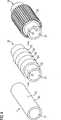
In einer bevorzugten Ausführungsform der Erfindung umschließt der wenigstens eine thermoelektrische Generator die Kühlmittelleitung außenumfänglich. Besonders zweckmäßig ist es, wenn der thermoelektrische Generator auf der Außenumfangsfläche einer Kühlmittelleitung mit rundem Querschnitt angeordnet ist. Der thermoelektrische Generator wird also mit anderen Worten in einen im Abgasstrom angeordneten Rohrwärmetauscher integriert. Dies ist eine besonders einfache und robuste Anordnung. Der thermoelektrische Generator kann in dieser Ausführungsform beispielsweise besonders einfach durch Aufspritzen von alternierenden p- und n-dotierten Halbleiterelementen auf den Rohrumfang gefertigt werden.In a preferred embodiment of the invention, the at least one thermoelectric generator surrounds the outside of the coolant line. It is particularly expedient if the thermoelectric generator is arranged on the outer peripheral surface of a coolant line with a round cross section. In other words, the thermoelectric generator is integrated into a tube heat exchanger arranged in the exhaust gas stream. This is a particularly simple and robust arrangement. The thermoelectric generator can be made in this embodiment, for example, particularly simple by spraying of alternating p- and n-doped semiconductor elements on the tube circumference.
Alternativ können auch plattenförmige thermoelektrische Generator-Module Anwendung finden. Derartige Module können beispielsweise so angeordnet werden, dass die Kühlmittelleitung als Spalt zwischen gegenüberliegenden Paaren von plattenförmigen thermoelektrischen Generatoren ausgebildet ist. Durch die Sandwich-artige Bauweise werden die Module jeweils paarweise mit Kühlmedium der gleichen Temperatur beaufschlagt, was eine besonders effiziente Kühlung erlaubt. Gleichzeitig ermöglicht diese Ausführungsform die Verwendung von Modulen im üblichen Flachbauformat, die mit gängigen Rippenwärmetauschern versehen werden können, und ist daher besonders kostengünstig.Alternatively, plate-shaped thermoelectric generator modules can be used. Such modules may for example be arranged so that the coolant line is formed as a gap between opposing pairs of plate-shaped thermoelectric generators. Due to the sandwich-like design, the modules are each exposed in pairs to cooling medium of the same temperature, which allows a particularly efficient cooling. At the same time, this embodiment allows the use of modules in the usual flat design, which can be provided with common rib heat exchangers, and is therefore particularly cost.
Die Erfindung betrifft ferner ein Kraftwerk mit einer Gasturbinenanordnung der geschilderten Art.The invention further relates to a power plant with a gas turbine arrangement of the type described.
Die von dem wenigstens einen thermoelektrischen Generator im Betrieb bereitgestellte elektrische Energie kann bei einem solchen Kraftwerk über eine Leistungselektronik gemeinsam mit von einem durch die Turbinenanordnung angetriebenen elektrischen Generator im Betrieb bereitgestellter elektrischer Energie in ein mit dem Kraftwerk gekoppeltes Stromnetz eingespeist werden, um den Gesamtwirkungsgrad des Kraftwerks zu erhöhen und mehr Netzenergie bereitzustellen.The electrical energy provided by the at least one thermoelectric generator in operation can be fed into a power grid coupled to the power plant in such a power plant via power electronics together with electrical power provided by the turbine generator in operation to provide the overall efficiency of the power plant increase and provide more network power.
Alternativ ist es auch möglich, dass von dem wenigstens einen thermoelektrischen Generator im Betrieb bereitgestellte elektrische Energie in ein kraftwerksinternes Stromnetz zum Versorgen von dem Kraftwerk zugeordneten Verbrauchern einspeisbar ist. Auch dies führt zur gewünschten Wirkungsgraderhöhung und hat den zusätzlichen Vorteil, eine gegebenenfalls vorhandene Abhängigkeit der Kraftwerksverbraucher von externen Stromquellen zu reduzieren, so dass außerhalb einer unmittelbaren Kaltstartphase ein autonomer Betrieb des Kraftwerks ermöglicht wird.Alternatively, it is also possible for electrical energy provided by the at least one thermoelectric generator during operation to be fed into a power plant internal power network for supplying consumers assigned to the power plant. This also leads to the desired increase in efficiency and has the additional advantage of an optionally existing dependence of To reduce power plant consumers from external power sources, so that outside of an immediate cold start phase autonomous operation of the power plant is made possible.
Schließlich betrifft die Erfindung noch ein Verfahren zum Betreiben eines Kraftwerks mit einer Gasturbinenanordnung, in welcher Treibstoff zusammen mit mittels eines Kompressors verdichteter Verbrennungsluft verbrannt wird und mittels der Verbrennungsgase eine mit dem Kompressor mechanisch gekoppelte Turbine angetrieben wird, wobei die Verbrennungsgase über einen Abgasstrang an die Umgebung abgegeben werden. Erfindungsgemäß ist dabei vorgesehen, dass Restwärme der Abgase mittels wenigstens eines thermoelektrischen Generators zumindest teilweise in elektrische Energie umgewandelt wird.Finally, the invention also relates to a method for operating a power plant with a gas turbine arrangement in which fuel is burned together with compressed by a compressor combustion air and combustion means of the combustion gases mechanically coupled to the compressor turbine is driven, the combustion gases via an exhaust system to the environment be delivered. According to the invention it is provided that residual heat of the exhaust gases is at least partially converted into electrical energy by means of at least one thermoelectric generator.
Wie bereits anhand der erfindungsgemäßen Gasturbinenanordnung erläutert, wird auf diese Art der Gesamtwirkungsgrad des Kraftwerks erhöht, so dass bei gleicher Energieabgabe weniger Kraftstoff verbraucht und weniger CO2 und andere Schadstoffe an die Umwelt abgegeben werden. Auch hier bestehen die anhand der Ausführungsbeispiele des erfindungsgemäßen Kraftwerks erläuterten Möglichkeiten und Vorteile bezüglich der Einspeisung der gewonnenen elektrischen Energie.As already explained with reference to the gas turbine arrangement according to the invention, in this way the overall efficiency of the power plant is increased, so that with the same energy output less fuel consumed and less CO2 and other pollutants are released to the environment. Again, there are explained with reference to the embodiments of the power plant according to the invention possibilities and advantages with respect to the feed of the electrical energy obtained.
Im Folgenden werden die Erfindung und ihre Ausführungsformen anhand der Zeichnung näher erläutert. Es zeigen:In the following the invention and its embodiments will be explained in more detail with reference to the drawing. Show it:
Eine im Ganzen mit
Nach Durchtritt durch die Turbine
Wärmeenergie aus den heißen Verbrennungsgasen passiert entlang des Gradienten zwischen Wärmetauscher
Durch die Abwärmenutzung kann der Wirkungsgrad der Gasturbinenanordnung
Bei der Auslegung von Wärmetauscher
Die Betriebstemperatur des thermoelektrischen Generators
Ein erstes Ausführungsbeispiel einer Moduleinheit
Im Abgasstrang
Auch in Richtung der Gasströmung kann eine Mehrzahl von Moduleinheiten
Für eine Abwärmenutzung im Abgastemperaturbereich von 570°C–230°C mittels durchgängig angeordneter Moduleinheiten
Werden dagegen streifenförmige Moduleinheiten
Metallische Verbindungsringe
Claims (17)
Translated fromGermanPriority Applications (5)
| Application Number | Priority Date | Filing Date | Title |
|---|---|---|---|
| DE102011081565ADE102011081565A1 (en) | 2011-08-25 | 2011-08-25 | Gas turbine arrangement, power plant and method for its operation |
| US14/236,555US9806247B2 (en) | 2011-08-25 | 2012-08-08 | Gas turbine arrangement, power plant and method for the operation thereof |
| EP12748002.8AEP2707584B1 (en) | 2011-08-25 | 2012-08-08 | Gas turbine arrangement, power plant and method for the operation thereof |
| JP2014526440AJP6008966B2 (en) | 2011-08-25 | 2012-08-08 | Gas turbine device, power plant and method of operating the power plant |
| PCT/EP2012/065493WO2013026702A2 (en) | 2011-08-25 | 2012-08-08 | Gas turbine arrangement, power plant and method for the operation thereof |
Applications Claiming Priority (1)
| Application Number | Priority Date | Filing Date | Title |
|---|---|---|---|
| DE102011081565ADE102011081565A1 (en) | 2011-08-25 | 2011-08-25 | Gas turbine arrangement, power plant and method for its operation |
Publications (1)
| Publication Number | Publication Date |
|---|---|
| DE102011081565A1true DE102011081565A1 (en) | 2013-02-28 |
Family
ID=46682814
Family Applications (1)
| Application Number | Title | Priority Date | Filing Date |
|---|---|---|---|
| DE102011081565ACeasedDE102011081565A1 (en) | 2011-08-25 | 2011-08-25 | Gas turbine arrangement, power plant and method for its operation |
Country Status (5)
| Country | Link |
|---|---|
| US (1) | US9806247B2 (en) |
| EP (1) | EP2707584B1 (en) |
| JP (1) | JP6008966B2 (en) |
| DE (1) | DE102011081565A1 (en) |
| WO (1) | WO2013026702A2 (en) |
Cited By (2)
| Publication number | Priority date | Publication date | Assignee | Title |
|---|---|---|---|---|
| WO2016001117A1 (en)* | 2014-06-30 | 2016-01-07 | Würth Elektronik eiSos Gmbh & Co. KG | Device and method for generating electrical energy |
| DE102020212473B3 (en) | 2020-10-01 | 2021-12-09 | Vitesco Technologies GmbH | Heat exchanger with thermoelectric generator |
Families Citing this family (36)
| Publication number | Priority date | Publication date | Assignee | Title |
|---|---|---|---|---|
| DE102010038314A1 (en)* | 2010-07-23 | 2012-01-26 | Bayerische Motoren Werke Aktiengesellschaft | Drive system for a vehicle |
| DE102012219968A1 (en)* | 2012-10-31 | 2014-06-12 | Bayerische Motoren Werke Aktiengesellschaft | Exhaust system with thermoelectric generator |
| WO2015073101A2 (en) | 2013-09-16 | 2015-05-21 | United Technologies Corporation | Systems for generating auxillary electrical power for jet aircraft propulsion systems |
| KR101745522B1 (en) | 2015-12-01 | 2017-06-20 | 재단법인 포항산업과학연구원 | Auxiliary combustion device of exhaust gas cleaning equipment |
| US11222830B2 (en)* | 2018-01-03 | 2022-01-11 | Lenovo (Beijing) Co., Ltd. | Heat dissipation structure and electronic device |
| CA3092865C (en) | 2019-09-13 | 2023-07-04 | Bj Energy Solutions, Llc | Power sources and transmission networks for auxiliary equipment onboard hydraulic fracturing units and associated methods |
| US10815764B1 (en) | 2019-09-13 | 2020-10-27 | Bj Energy Solutions, Llc | Methods and systems for operating a fleet of pumps |
| US12065968B2 (en) | 2019-09-13 | 2024-08-20 | BJ Energy Solutions, Inc. | Systems and methods for hydraulic fracturing |
| US10895202B1 (en) | 2019-09-13 | 2021-01-19 | Bj Energy Solutions, Llc | Direct drive unit removal system and associated methods |
| CA3197583A1 (en) | 2019-09-13 | 2021-03-13 | Bj Energy Solutions, Llc | Fuel, communications, and power connection systems and related methods |
| CA3092829C (en) | 2019-09-13 | 2023-08-15 | Bj Energy Solutions, Llc | Methods and systems for supplying fuel to gas turbine engines |
| US11015594B2 (en) | 2019-09-13 | 2021-05-25 | Bj Energy Solutions, Llc | Systems and method for use of single mass flywheel alongside torsional vibration damper assembly for single acting reciprocating pump |
| CA3092863C (en) | 2019-09-13 | 2023-07-18 | Bj Energy Solutions, Llc | Fuel, communications, and power connection systems and related methods |
| US11002189B2 (en) | 2019-09-13 | 2021-05-11 | Bj Energy Solutions, Llc | Mobile gas turbine inlet air conditioning system and associated methods |
| US12338772B2 (en) | 2019-09-13 | 2025-06-24 | Bj Energy Solutions, Llc | Systems, assemblies, and methods to enhance intake air flow to a gas turbine engine of a hydraulic fracturing unit |
| US11708829B2 (en) | 2020-05-12 | 2023-07-25 | Bj Energy Solutions, Llc | Cover for fluid systems and related methods |
| US10968837B1 (en) | 2020-05-14 | 2021-04-06 | Bj Energy Solutions, Llc | Systems and methods utilizing turbine compressor discharge for hydrostatic manifold purge |
| US11428165B2 (en) | 2020-05-15 | 2022-08-30 | Bj Energy Solutions, Llc | Onboard heater of auxiliary systems using exhaust gases and associated methods |
| US11208880B2 (en) | 2020-05-28 | 2021-12-28 | Bj Energy Solutions, Llc | Bi-fuel reciprocating engine to power direct drive turbine fracturing pumps onboard auxiliary systems and related methods |
| US11208953B1 (en) | 2020-06-05 | 2021-12-28 | Bj Energy Solutions, Llc | Systems and methods to enhance intake air flow to a gas turbine engine of a hydraulic fracturing unit |
| US11109508B1 (en) | 2020-06-05 | 2021-08-31 | Bj Energy Solutions, Llc | Enclosure assembly for enhanced cooling of direct drive unit and related methods |
| US11066915B1 (en) | 2020-06-09 | 2021-07-20 | Bj Energy Solutions, Llc | Methods for detection and mitigation of well screen out |
| US10954770B1 (en) | 2020-06-09 | 2021-03-23 | Bj Energy Solutions, Llc | Systems and methods for exchanging fracturing components of a hydraulic fracturing unit |
| US11125066B1 (en) | 2020-06-22 | 2021-09-21 | Bj Energy Solutions, Llc | Systems and methods to operate a dual-shaft gas turbine engine for hydraulic fracturing |
| US11939853B2 (en) | 2020-06-22 | 2024-03-26 | Bj Energy Solutions, Llc | Systems and methods providing a configurable staged rate increase function to operate hydraulic fracturing units |
| US11028677B1 (en) | 2020-06-22 | 2021-06-08 | Bj Energy Solutions, Llc | Stage profiles for operations of hydraulic systems and associated methods |
| US11933153B2 (en) | 2020-06-22 | 2024-03-19 | Bj Energy Solutions, Llc | Systems and methods to operate hydraulic fracturing units using automatic flow rate and/or pressure control |
| US20220065125A1 (en)* | 2020-06-23 | 2022-03-03 | Bj Energy Solutions, Llc | Energy recovery for high power pumping systems and methods using exhaust gas heat to generate thermoelectric power |
| US11466680B2 (en) | 2020-06-23 | 2022-10-11 | Bj Energy Solutions, Llc | Systems and methods of utilization of a hydraulic fracturing unit profile to operate hydraulic fracturing units |
| US11473413B2 (en) | 2020-06-23 | 2022-10-18 | Bj Energy Solutions, Llc | Systems and methods to autonomously operate hydraulic fracturing units |
| US11220895B1 (en) | 2020-06-24 | 2022-01-11 | Bj Energy Solutions, Llc | Automated diagnostics of electronic instrumentation in a system for fracturing a well and associated methods |
| US11149533B1 (en) | 2020-06-24 | 2021-10-19 | Bj Energy Solutions, Llc | Systems to monitor, detect, and/or intervene relative to cavitation and pulsation events during a hydraulic fracturing operation |
| US11193360B1 (en) | 2020-07-17 | 2021-12-07 | Bj Energy Solutions, Llc | Methods, systems, and devices to enhance fracturing fluid delivery to subsurface formations during high-pressure fracturing operations |
| CN112727603A (en)* | 2020-12-09 | 2021-04-30 | 华电电力科学研究院有限公司 | Combined power generation method applied to land desert simple cycle gas turbine power generation and thermoelectric power generation |
| US11639654B2 (en) | 2021-05-24 | 2023-05-02 | Bj Energy Solutions, Llc | Hydraulic fracturing pumps to enhance flow of fracturing fluid into wellheads and related methods |
| CA3180024A1 (en) | 2021-10-25 | 2023-04-25 | Bj Energy Solutions, Llc | Systems and methods to reduce acoustic resonance or disrupt standing wave formation in a fluid manifold of a high-pressure fracturing system |
Citations (4)
| Publication number | Priority date | Publication date | Assignee | Title |
|---|---|---|---|---|
| DE1149573B (en)* | 1959-06-01 | 1963-05-30 | Havilland Engine Company De | Thermal power plant with a gas turbine system consisting of a compressor, combustion chamber and gas turbine |
| US3719532A (en)* | 1969-06-25 | 1973-03-06 | Siemens Ag | Thermogenerator with thermoelectric elements in exhaust ducts |
| US5550410A (en)* | 1994-08-02 | 1996-08-27 | Titus; Charles H. | Gas turbine electrical power generation scheme utilizing remotely located fuel sites |
| US20040045594A1 (en)* | 2002-09-10 | 2004-03-11 | Enhanced Energy Systems, Inc. | Turbine engine with thermoelectric waste heat recovery system |
Family Cites Families (24)
| Publication number | Priority date | Publication date | Assignee | Title |
|---|---|---|---|---|
| DE1476854A1 (en) | 1965-11-09 | 1969-10-09 | Plessey Co Ltd | Gas turbine engine |
| JP2808456B2 (en)* | 1989-03-09 | 1998-10-08 | 三菱重工業株式会社 | Steam turbine power plant |
| JPH0638560A (en)* | 1992-07-20 | 1994-02-10 | Aisin Seiki Co Ltd | Exhaust gas power generator |
| JPH11289783A (en)* | 1998-03-31 | 1999-10-19 | Hakko Denki Kk | Solar power generator |
| EP1245052A2 (en)* | 2000-01-07 | 2002-10-02 | University Of Southern California | Microcombustor and combustion-based thermoelectric microgenerator |
| JP3526026B2 (en)* | 2000-06-05 | 2004-05-10 | トヨタ自動車株式会社 | Waste heat recovery method for gas turbine power generation system |
| JP2002238272A (en)* | 2001-02-06 | 2002-08-23 | Tokyo Gas Co Ltd | High-temperature waste heat power generator |
| JP2002325470A (en) | 2001-04-23 | 2002-11-08 | Sango Co Ltd | Automotive thermoelectric generator |
| US6698500B2 (en)* | 2002-01-22 | 2004-03-02 | The Furukawa Electric Co., Ltd. | Heat sink with fins |
| US20030188848A1 (en)* | 2002-04-08 | 2003-10-09 | Yu-Chen Kuo | Complex heat-radiator |
| EP1611323B1 (en) | 2002-12-26 | 2010-11-17 | Toyota Jidosha Kabushiki Kaisha | Exhaust system |
| JP2004208476A (en) | 2002-12-26 | 2004-07-22 | Toyota Motor Corp | Waste heat power generator |
| JP4366114B2 (en)* | 2003-05-15 | 2009-11-18 | 株式会社小松製作所 | Thermoelectric generator |
| US20050022855A1 (en)* | 2003-07-30 | 2005-02-03 | Raver Bernard J. | Thermoelectric power generator for a gas turbine engine |
| JP2006214350A (en)* | 2005-02-03 | 2006-08-17 | Toyota Motor Corp | Thermoelectric generator |
| US7228887B2 (en)* | 2005-02-23 | 2007-06-12 | Asia Vital Component Co., Ltd. | Radiator structure |
| JP4660240B2 (en)* | 2005-03-25 | 2011-03-30 | 株式会社東芝 | Temperature difference power generation system |
| JP4929004B2 (en)* | 2007-03-23 | 2012-05-09 | 三菱重工業株式会社 | Gas turbine power generation system |
| JP2009293390A (en)* | 2008-06-02 | 2009-12-17 | Honda Motor Co Ltd | Gas turbine engine |
| JP2010057335A (en)* | 2008-08-29 | 2010-03-11 | Techno Sansho:Kk | Water-cooling power generation unit |
| FR2942077B1 (en) | 2009-02-06 | 2013-08-16 | Turbomeca | THERMOELECTRIC GENERATION FOR GAS TURBINE |
| DE102009033613A1 (en)* | 2009-07-17 | 2011-01-20 | Emitec Gesellschaft Für Emissionstechnologie Mbh | Thermoelectric device with tube bundles |
| US8578696B2 (en)* | 2010-08-03 | 2013-11-12 | General Electric Company | Turbulated arrangement of thermoelectric elements for utilizing waste heat generated from turbine engine |
| US20120118345A1 (en)* | 2010-11-15 | 2012-05-17 | The Boeing Company | Thermal integration of thermoelectronic device |
- 2011
- 2011-08-25DEDE102011081565Apatent/DE102011081565A1/ennot_activeCeased
- 2012
- 2012-08-08WOPCT/EP2012/065493patent/WO2013026702A2/enactiveApplication Filing
- 2012-08-08JPJP2014526440Apatent/JP6008966B2/enactiveActive
- 2012-08-08USUS14/236,555patent/US9806247B2/enactiveActive
- 2012-08-08EPEP12748002.8Apatent/EP2707584B1/enactiveActive
Patent Citations (4)
| Publication number | Priority date | Publication date | Assignee | Title |
|---|---|---|---|---|
| DE1149573B (en)* | 1959-06-01 | 1963-05-30 | Havilland Engine Company De | Thermal power plant with a gas turbine system consisting of a compressor, combustion chamber and gas turbine |
| US3719532A (en)* | 1969-06-25 | 1973-03-06 | Siemens Ag | Thermogenerator with thermoelectric elements in exhaust ducts |
| US5550410A (en)* | 1994-08-02 | 1996-08-27 | Titus; Charles H. | Gas turbine electrical power generation scheme utilizing remotely located fuel sites |
| US20040045594A1 (en)* | 2002-09-10 | 2004-03-11 | Enhanced Energy Systems, Inc. | Turbine engine with thermoelectric waste heat recovery system |
Cited By (2)
| Publication number | Priority date | Publication date | Assignee | Title |
|---|---|---|---|---|
| WO2016001117A1 (en)* | 2014-06-30 | 2016-01-07 | Würth Elektronik eiSos Gmbh & Co. KG | Device and method for generating electrical energy |
| DE102020212473B3 (en) | 2020-10-01 | 2021-12-09 | Vitesco Technologies GmbH | Heat exchanger with thermoelectric generator |
Also Published As
| Publication number | Publication date |
|---|---|
| JP2014524543A (en) | 2014-09-22 |
| JP6008966B2 (en) | 2016-10-19 |
| EP2707584A2 (en) | 2014-03-19 |
| US9806247B2 (en) | 2017-10-31 |
| WO2013026702A2 (en) | 2013-02-28 |
| WO2013026702A3 (en) | 2013-05-02 |
| US20140174097A1 (en) | 2014-06-26 |
| EP2707584B1 (en) | 2018-12-12 |
Similar Documents
| Publication | Publication Date | Title |
|---|---|---|
| EP2707584B1 (en) | Gas turbine arrangement, power plant and method for the operation thereof | |
| EP2694878B1 (en) | Gas turbine assembly and corresponding operating method | |
| EP3129610B1 (en) | Method and device for storing and recovering energy | |
| EP2329555B1 (en) | Air supply unit for a fuel cell stack, fuel cell system and method for operating an air supply unit | |
| EP2808500A1 (en) | Heat pump cycle with a first thermal fluid energy machine and a second thermal fluid energy machine | |
| CH698466B1 (en) | Combustion system with gas turbine and oxygen source. | |
| EP2447506A2 (en) | System for generating mechanical and/or electrical energy | |
| DE102011102599A1 (en) | Method for operating a small gas turbine arrangement, and small gas turbine arrangement itself | |
| DE19501471A1 (en) | Internal combustion gas turbine | |
| EP2439799A1 (en) | Thermoelectric converter and heat exchanger tubes | |
| EP0462458A1 (en) | Method to increase the compressor pressure ratio of a gas turbine plant | |
| EP2839135A1 (en) | Micro gas turbine system with a pipe-shaped recuperator | |
| CH701999A2 (en) | Steam turbine with cooling of the steam turbine impellers. | |
| EP2876280B1 (en) | Micro gas turbine assembly | |
| DE102007027725A1 (en) | Method for producing useful heating and cooling energy, involves absorbing ambient air with turbo-heat pump, where compressed and warmed up air is produced in compression impeller of heat pump | |
| DE102020212473B3 (en) | Heat exchanger with thermoelectric generator | |
| DE102004004914B4 (en) | Method for generating electricity and heat | |
| EP1798472B1 (en) | Gas turbine combustion chamber | |
| DE4317947C1 (en) | Heat-conversion system into mechanical work | |
| EP1500808A1 (en) | System and method for controlling the temperature of an internal combustion engine exhaust gas temperature | |
| EP1557607B1 (en) | Burner with cooled component, gas turbine and method for cooling the component | |
| DE102012004275A1 (en) | Device for generating electricity from waste heat in hermetically operated heat- and power-combination plant, has liquefier whose outlet is moved to pump, where exhaust system downstream to power engine is guided in direction of liquefier | |
| DE102013100342B4 (en) | A gas turbine apparatus and method of operating a gas turbine apparatus | |
| EP3690204A1 (en) | Storage device and method for heat storage and (back) conversion into electrical energy | |
| EP2876281A1 (en) | Micro gas turbine assembly |
Legal Events
| Date | Code | Title | Description |
|---|---|---|---|
| R012 | Request for examination validly filed | ||
| R002 | Refusal decision in examination/registration proceedings | ||
| R003 | Refusal decision now final | Effective date:20130702 |