DE102011079136A1 - Direct plug-in element with integrated lock - Google Patents
Direct plug-in element with integrated lockDownload PDFInfo
- Publication number
- DE102011079136A1 DE102011079136A1DE102011079136ADE102011079136ADE102011079136A1DE 102011079136 A1DE102011079136 A1DE 102011079136A1DE 102011079136 ADE102011079136 ADE 102011079136ADE 102011079136 ADE102011079136 ADE 102011079136ADE 102011079136 A1DE102011079136 A1DE 102011079136A1
- Authority
- DE
- Germany
- Prior art keywords
- contact
- direct
- plug
- direct contact
- tab
- Prior art date
- Legal status (The legal status is an assumption and is not a legal conclusion. Google has not performed a legal analysis and makes no representation as to the accuracy of the status listed.)
- Withdrawn
Links
- 230000000295complement effectEffects0.000claimsabstractdescription4
- 239000000463materialSubstances0.000claimsdescription24
- 238000004519manufacturing processMethods0.000claimsdescription13
- 238000004080punchingMethods0.000claimsdescription5
- 238000005452bendingMethods0.000claimsdescription3
- 239000004020conductorSubstances0.000claimsdescription3
- 239000011248coating agentSubstances0.000claimsdescription2
- 238000000576coating methodMethods0.000claimsdescription2
- 238000003780insertionMethods0.000description8
- 230000037431insertionEffects0.000description8
- 238000000034methodMethods0.000description7
- PXHVJJICTQNCMI-UHFFFAOYSA-NNickelChemical compound[Ni]PXHVJJICTQNCMI-UHFFFAOYSA-N0.000description2
- ATJFFYVFTNAWJD-UHFFFAOYSA-NTinChemical compound[Sn]ATJFFYVFTNAWJD-UHFFFAOYSA-N0.000description1
- 230000001133accelerationEffects0.000description1
- 238000002788crimpingMethods0.000description1
- 230000001419dependent effectEffects0.000description1
- 238000011161developmentMethods0.000description1
- 230000018109developmental processEffects0.000description1
- 238000009713electroplatingMethods0.000description1
- 238000004049embossingMethods0.000description1
- PCHJSUWPFVWCPO-UHFFFAOYSA-NgoldChemical compound[Au]PCHJSUWPFVWCPO-UHFFFAOYSA-N0.000description1
- 229910052737goldInorganic materials0.000description1
- 239000010931goldSubstances0.000description1
- 229910052759nickelInorganic materials0.000description1
- 239000011295pitchSubstances0.000description1
- 238000003825pressingMethods0.000description1
- 238000000926separation methodMethods0.000description1
- 239000000758substrateSubstances0.000description1
- 229910052718tinInorganic materials0.000description1
- 239000011135tinSubstances0.000description1
- 238000003466weldingMethods0.000description1
Images


Classifications
- H—ELECTRICITY
- H01—ELECTRIC ELEMENTS
- H01R—ELECTRICALLY-CONDUCTIVE CONNECTIONS; STRUCTURAL ASSOCIATIONS OF A PLURALITY OF MUTUALLY-INSULATED ELECTRICAL CONNECTING ELEMENTS; COUPLING DEVICES; CURRENT COLLECTORS
- H01R13/00—Details of coupling devices of the kinds covered by groups H01R12/70 or H01R24/00 - H01R33/00
- H01R13/40—Securing contact members in or to a base or case; Insulating of contact members
- H01R13/42—Securing in a demountable manner
- H01R13/428—Securing in a demountable manner by resilient locking means on the contact members; by locking means on resilient contact members
- H—ELECTRICITY
- H01—ELECTRIC ELEMENTS
- H01R—ELECTRICALLY-CONDUCTIVE CONNECTIONS; STRUCTURAL ASSOCIATIONS OF A PLURALITY OF MUTUALLY-INSULATED ELECTRICAL CONNECTING ELEMENTS; COUPLING DEVICES; CURRENT COLLECTORS
- H01R13/00—Details of coupling devices of the kinds covered by groups H01R12/70 or H01R24/00 - H01R33/00
- H01R13/62—Means for facilitating engagement or disengagement of coupling parts or for holding them in engagement
- H—ELECTRICITY
- H01—ELECTRIC ELEMENTS
- H01R—ELECTRICALLY-CONDUCTIVE CONNECTIONS; STRUCTURAL ASSOCIATIONS OF A PLURALITY OF MUTUALLY-INSULATED ELECTRICAL CONNECTING ELEMENTS; COUPLING DEVICES; CURRENT COLLECTORS
- H01R43/00—Apparatus or processes specially adapted for manufacturing, assembling, maintaining, or repairing of line connectors or current collectors or for joining electric conductors
- H01R43/26—Apparatus or processes specially adapted for manufacturing, assembling, maintaining, or repairing of line connectors or current collectors or for joining electric conductors for engaging or disengaging the two parts of a coupling device
- Y—GENERAL TAGGING OF NEW TECHNOLOGICAL DEVELOPMENTS; GENERAL TAGGING OF CROSS-SECTIONAL TECHNOLOGIES SPANNING OVER SEVERAL SECTIONS OF THE IPC; TECHNICAL SUBJECTS COVERED BY FORMER USPC CROSS-REFERENCE ART COLLECTIONS [XRACs] AND DIGESTS
- Y10—TECHNICAL SUBJECTS COVERED BY FORMER USPC
- Y10T—TECHNICAL SUBJECTS COVERED BY FORMER US CLASSIFICATION
- Y10T29/00—Metal working
- Y10T29/49—Method of mechanical manufacture
- Y10T29/49002—Electrical device making
- Y10T29/49117—Conductor or circuit manufacturing
- Y10T29/49204—Contact or terminal manufacturing
- Y10T29/49224—Contact or terminal manufacturing with coating
Landscapes
- Engineering & Computer Science (AREA)
- Manufacturing & Machinery (AREA)
- Coupling Device And Connection With Printed Circuit (AREA)
- Connector Housings Or Holding Contact Members (AREA)
- Details Of Connecting Devices For Male And Female Coupling (AREA)
- Manufacturing Of Electrical Connectors (AREA)
Abstract
Translated fromGermanDescription
Translated fromGermanStand der TechnikState of the art
Die vorliegende Erfindung betrifft ein Direktsteckelement mit einem Steckergehäuse und einem Direktkontakt für eine Direktkontaktierung von freiliegenden Kontaktbereichen an einem Gegenstück, beispielsweise einer Leiterplatte, sowie eine elektrische Anordnung mit einem derartigen Direktsteckelement.The present invention relates to a direct plug-in element with a plug housing and a direct contact for direct contacting of exposed contact areas on a counterpart, for example a printed circuit board, and an electrical arrangement with such a direct plug-in element.
In jüngster Zeit werden vermehrt Direktsteckkontakte verwendet, bei denen ein Direktsteckelement unmittelbar auf ein Gegenstück, wie z. B. eine Leiterplatte oder ein Stanzgitter oder Substrat gesteckt wird. Insbesondere bei der Verwendung im Fahrzeugbereich ergeben sich jedoch erhöhte Anforderungen hinsichtlich einer Robustheit und Kontaktsicherheit derartiger Direktsteckverbindungen. Bisher weisen Direktsteckelemente einen aufwändigen Aufbau auf, bei dem Direktkontakte durch zusätzliche Bauteile auf ein Gegenstück angepresst bzw. in einem Steckergehäuse verrastet werden. Es ist jedoch wünschenswert, insbesondere bei Massenprodukten, wie beispielsweise Direktsteckelementen für Steuergeräte in Fahrzeugen, einen möglichst einfachen Aufbau mit hoher Kontaktsicherheit bereitzustellen, der zudem eine wirtschaftliche Herstellung ermöglicht.Recently, more direct plug contacts are used in which a direct plug directly on a counterpart such. B. a circuit board or a lead frame or substrate is inserted. However, in particular when used in the vehicle sector, there are increased requirements with regard to the robustness and contact reliability of such direct plug connections. So far, direct plug-in elements have a complex structure in which direct contacts are pressed by additional components on a counterpart or locked in a connector housing. However, it is desirable, in particular for mass products, such as direct plug-in elements for control units in vehicles, to provide the simplest possible structure with high contact reliability, which also enables economical production.
Offenbarung der ErfindungDisclosure of the invention
Das erfindungsgemäße Direktsteckelement mit den Merkmalen des Anspruchs 1 weist den Vorteil auf, dass keine zusätzlichen Bauteile zur Erzeugung der Kontaktkraft auf einem Gegenstück erforderlich sind und ein Direktkontakt selbstverrastend ist. Somit wird ein einfach aufgebautes Direktsteckelement mit einer integrierten Verriegelung bereitgestellt. Dies wird erfindungsgemäß dadurch erreicht, dass das Direktsteckelement ein Steckergehäuse und einen Direktkontakt mit einer Kontaktlasche umfasst, wobei die Kontaktlasche wenigstens einen Kontaktabschnitt für eine Direktkontaktierung mit einem freiliegenden Kontaktbereich an einem Gegenstück aufweist. Ferner ist eine Rastverbindung zwischen dem Steckergehäuse und dem Direktkontakt vorgesehen, um den im Steckergehäuse angeordneten Direktkontakt im Steckergehäuse zu halten. Die Rastvorrichtung weist ein erstes Rastelement am Direktkontakt auf, welches eingerichtet ist, um mit einem komplementär zum ersten Rastelement gebildeten zweiten Rastelement am Steckergehäuse in Rastverbindung zu treten. Hierbei ist das erste Rastelement an einer Flachseite des Direktkontakts angeordnet und der Kontaktabschnitt an einer der Schmalseiten der Kontaktlasche angeordnet. Hierdurch wird ein Direktsteckelement mit einer Rastvorrichtung bereitgestellt, welche eine selbsttätige Verrastung des Direktkontakts mit dem Steckergehäuse durch deren jeweilige Eigenform ermöglicht. Aufgrund der minimierten Bauteileanzahl wird zudem eine kosteneffiziente und wirtschaftliche Massenfertigung der Bauteile erreicht. Die erfindungsgemäße Kontaktlasche weist somit eine sehr weiche Federfunktion auf, da die Kontaktlasche eine große Länge aufweisen kann, vorzugsweise mehr als die Hälfte, besonders bevorzugt mehr als 3/4 einer Gesamtlänge des Direktsteckelements. Dabei ist die erfindungsgemäße Kontaktlasche sehr stabil und kann auch höheren Belastungen widerstehen. Dies ist insbesondere bei miniaturisierten Kontakten ein wesentlicher Vorteil.The direct plug-in element according to the invention with the features of
Die Unteransprüche zeigen bevorzugte Weiterbildungen der Erfindung.The dependent claims show preferred developments of the invention.
Gemäß einer bevorzugten Ausgestaltung der Erfindung weist die Kontaktlasche einen ersten und zweiten Kontaktabschnitt auf, wobei jeweils einer der Kontaktabschnitte an einer der Schmalseiten der Kontaktlasche angeordnet ist. Durch die gegenüberliegende, seitliche Anordnung der Kontaktabschnitte an der Kontaktlasche wird eine unter allen Betriebsbedingungen und Einsatzarten besonders betriebssichere Direktkontaktierung mit den Kontaktbereichen des Gegenstücks gewährleistet. Zudem kann die Kontaktlasche durch einfache Stanz- und Biegeschritte in kurzen Taktzeiten kostengünstig gefertigt werden.According to a preferred embodiment of the invention, the contact tab on a first and second contact portion, wherein each one of the contact portions is disposed on one of the narrow sides of the contact tab. By the opposite, lateral arrangement of the contact portions on the contact tab a particularly reliable direct contact with the contact areas of the counterpart is guaranteed under all operating conditions and types of use. In addition, the contact tab can be manufactured inexpensively by simple punching and bending steps in short cycle times.
Besonders bevorzugt ist die Kontaktlasche bogenförmig gebildet und weist federnde Eigenschaften in Richtung der Rastvorrichtung auf. Weiterhin bevorzugt ist das erste Rastelement an einem konvexen Bereich der bogenförmigen Kontaktlasche angeordnet. Beim Rastvorgang kann die Kontaktlasche aufgrund dieser Formgebung senkrecht zu einer Einschubrichtung elastisch einfedern bzw. durch ihre Eigenform gebogen werden, sodass das erste Rastelement über das zweite Rastelement am Steckergehäuse geschoben werden kann und mit diesem selbsttätig verrastet. Für die Feder- und Rastfunktion sind hierbei keine zusätzlichen Bauteile erforderlich.Particularly preferably, the contact tab is arc-shaped and has resilient properties in the direction of the latching device. Further preferably, the first latching element is arranged on a convex region of the arcuate contact tab. During the latching process, the contact tab can be elastically deflected perpendicular to an insertion direction due to this shape or be bent by their own shape, so that the first locking element can be pushed over the second locking element on the connector housing and locked automatically with this. For the spring and latching function here no additional components are required.
Gemäß einer bevorzugten Ausgestaltung der Erfindung ist die Rastverbindung lösbar. Dadurch ist z. B. im Reparaturfall ein Austausch der Bauteile des Direktsteckelements und/oder des Kabels möglich.According to a preferred embodiment of the invention, the latching connection is releasable. This is z. B. in case of repair replacement of the components of the direct plug and / or cable possible.
Weiterhin bevorzugt weist das Steckergehäuse eine stirnseitige Öffnung auf. Mittels eines speziellen Demontagewerkzeugs, das in die stirnseitige Öffnung des Steckergehäuses eingeführt wird, kann das erste Rastelement am Direktkontakt senkrecht zur Einschubrichtung elastisch verformt und über das zweite Rastelement am Steckergehäuse angehoben werden. Dadurch wird die Verrastung aufgehoben und der Direktkontakt kann auf einfache Weise am Kabel aus dem Steckergehäuse herausgezogen werden.Furthermore, the plug housing preferably has an end opening. By means of a special disassembly tool, which is inserted into the frontal opening of the plug housing, the first locking element can be elastically deformed on the direct contact perpendicular to the insertion direction and raised via the second locking element on the connector housing. As a result, the latch is released and the direct contact can be easily pulled out of the connector housing on the cable.
Vorzugsweise ist eine zweite Rastvorrichtung zwischen dem Direktkontakt und dem Steckergehäuse gebildet. Dadurch kann eine redundante Verrastung der Bauteile erreicht werden, die selbst unter erschwerten Betriebsbedingungen eine hohe Kontaktsicherheit des Direktsteckelements gewährleistet. Preferably, a second locking device between the direct contact and the connector housing is formed. As a result, a redundant locking of the components can be achieved, which ensures a high contact reliability of the direct plug-in element even under difficult operating conditions.
Weiterhin bevorzugt ist der Direktkontakt im Wesentlichen in Richtung eines Kabels ausgerichtet, welches am Direktkontakt, z. B. durch Crimpen oder Schweißen, fixiert ist. Durch die lineare Ausrichtung wird eine kompakte Bauform des Direktsteckelement mit minimaler Bauhöhe realisiert und ferner eine einfache Bestückung im Steckergehäuse bzw. Demontage aus dem Steckergehäuse ermöglicht.Further preferably, the direct contact is substantially aligned in the direction of a cable, which at the direct contact, z. B. by crimping or welding, is fixed. Due to the linear alignment a compact design of the direct plug element is realized with minimal height and also allows easy placement in the connector housing or disassembly from the connector housing.
Die Erfindung betrifft ferner eine elektrische Anordnung, die ein Gegenstück mit freiliegenden Kontaktbereichen und ein erfindungsgemäßes Direktsteckelement umfasst.The invention further relates to an electrical arrangement comprising a counterpart with exposed contact areas and a direct plug-in element according to the invention.
Weiterhin betrifft die Erfindung ein Verfahren zur Herstellung eines Direktkontakts, umfassend eine Kontaktlasche mit mindestens einem Kontaktabschnitt und einem Rastelement mit folgenden Schritten: Ausstanzen einer Außenkontur des Direktkontakts aus einem Bandmaterial und Stanzen eines Bereichs für das Rastelement an einer Flachseite des Direktkontakts, wobei der Direktkontakt noch an einem Bandmaterialrest hängt. Danach erfolgt das Herstellen des Kontaktabschnitts durch Umbiegen wenigstens eines Konturbereichs der Außenkontur und das Herstellen des Rastelements durch Herausdrücken des gestanzten Bereichs. In abschließenden Arbeitsschritten erfolgt das Drehen des Direktkontakts, welcher noch an dem Bandmaterialrest hängt, um einen Winkel, vorzugsweise 90°, relativ zum Bandmaterialrest, so dass der Kontaktabschnitt aus einer Bandmaterialebene vorsteht und das Beschichten des Kontaktabschnitts des Direktkontakts mit einem elektrisch leitfähigen Material. Hierbei werden die Kontaktabschnitte in einem einzigen Galvanikprozess, wie z. B. einem Roll-Brush-Verfahren, partiell vernickelt bzw. verzinnt oder vergoldet und dadurch hinsichtlich ihrer elektrischen Leitfähigkeitseigenschaften veredelt. Nachfolgend können die Kontaktabschnitte vom Bandmaterialrest abgeschnitten und vereinzelt werden.Furthermore, the invention relates to a method for producing a direct contact, comprising a contact tab having at least one contact portion and a latching element with the following steps: punching an outer contour of the direct contact of a strip material and punching a region for the latching element on a flat side of the direct contact, the direct contact still hanging on a piece of tape material. Thereafter, the production of the contact portion by bending at least a contour region of the outer contour and the manufacture of the locking element by pressing out of the stamped area. In concluding steps, the direct contact, which still hangs from the strip of strip material, is rotated by an angle, preferably 90 °, relative to the strip material so that the contact section protrudes from a strip of material plane and the contact section of the direct contact is coated with an electrically conductive material. Here, the contact portions in a single electroplating process, such. As a roll-brush method, partially nickel-plated or tinned or gold-plated and thereby finished in terms of their electrical conductivity properties. Subsequently, the contact portions of the strip material residue can be cut and separated.
Die Erfindung wird vorzugsweise bei Steuergeräten von Fahrzeugen verwendet.The invention is preferably used in control devices of vehicles.
Zeichnungdrawing
Nachfolgend wird ein Ausführungsbeispiel der Erfindung unter Bezugnahme auf die begleitende Zeichnung im Detail beschrieben. In der Zeichnung ist:Hereinafter, an embodiment of the invention will be described in detail with reference to the accompanying drawings. In the drawing is:
Bevorzugte Ausführungsform der ErfindungPreferred embodiment of the invention
Nachfolgend wird unter Bezugnahme auf
Wie aus
An der ersten Schmalseite
Wenn der Direktkontakt
Wie aus
Mittels der im erfindungsgemäßen Direktsteckelement
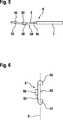
Zur Herstellung des Direktkontakts
Danach wird ein Endabschnitt
Wie in
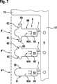
Nachfolgend wird mit Bezug auf
Die Herstellung des Direktkontakts
Wie in
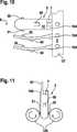
Ferner ermöglicht die erfindungsgemäße Herstellung des Direktsteckelements auch eine Montage in einem Stecker mit einer Vielzahl von Direktsteckelementen, wobei benachbarte Direktsteckelemente jeweils um 180° gedreht um ihre Längsachse abwechselnd bestückt sein können. Dabei ist es möglich, dass sich jeweils nur einer Kontaktabschnitte
Claims (10)
Translated fromGermanPriority Applications (7)
| Application Number | Priority Date | Filing Date | Title |
|---|---|---|---|
| DE102011079136ADE102011079136A1 (en) | 2011-07-14 | 2011-07-14 | Direct plug-in element with integrated lock |
| PCT/EP2012/063316WO2013007659A1 (en) | 2011-07-14 | 2012-07-06 | Direct plug-in element with integrated locking mechanism |
| KR1020147000836AKR101931094B1 (en) | 2011-07-14 | 2012-07-06 | Direct plug-in element with integrated locking mechanism |
| CN201280034533.0ACN103650248B (en) | 2011-07-14 | 2012-07-06 | Direct plug-in element with integrated locking mechanism |
| JP2014519510AJP5714183B2 (en) | 2011-07-14 | 2012-07-06 | Direct plug-in element with built-in locking device |
| US14/232,692US9608365B2 (en) | 2011-07-14 | 2012-07-06 | Direct plug-in element with integrated locking mechanism |
| EP12733701.2AEP2732508B1 (en) | 2011-07-14 | 2012-07-06 | Directly connecting element with latch |
Applications Claiming Priority (1)
| Application Number | Priority Date | Filing Date | Title |
|---|---|---|---|
| DE102011079136ADE102011079136A1 (en) | 2011-07-14 | 2011-07-14 | Direct plug-in element with integrated lock |
Publications (1)
| Publication Number | Publication Date |
|---|---|
| DE102011079136A1true DE102011079136A1 (en) | 2013-01-17 |
Family
ID=46506383
Family Applications (1)
| Application Number | Title | Priority Date | Filing Date |
|---|---|---|---|
| DE102011079136AWithdrawnDE102011079136A1 (en) | 2011-07-14 | 2011-07-14 | Direct plug-in element with integrated lock |
Country Status (7)
| Country | Link |
|---|---|
| US (1) | US9608365B2 (en) |
| EP (1) | EP2732508B1 (en) |
| JP (1) | JP5714183B2 (en) |
| KR (1) | KR101931094B1 (en) |
| CN (1) | CN103650248B (en) |
| DE (1) | DE102011079136A1 (en) |
| WO (1) | WO2013007659A1 (en) |
Families Citing this family (4)
| Publication number | Priority date | Publication date | Assignee | Title |
|---|---|---|---|---|
| US9847610B2 (en)* | 2014-01-16 | 2017-12-19 | Ford Global Technologies, Llc | Electric vehicle service disconnect position indicator |
| DE202019106842U1 (en)* | 2019-12-09 | 2019-12-18 | Häfele Berlin Gmbh & Co Kg | Connection bolt and associated connection fitting |
| DE202020104684U1 (en)* | 2020-08-12 | 2020-08-19 | Georg Schlegel Gmbh & Co. Kg | Device for assembling a housing |
| DE102021100806A1 (en) | 2021-01-15 | 2022-07-21 | Te Connectivity Germany Gmbh | Contact device and method for producing the contact device |
Citations (5)
| Publication number | Priority date | Publication date | Assignee | Title |
|---|---|---|---|---|
| DE1930199A1 (en)* | 1968-06-14 | 1970-01-29 | Amp Inc | Electrical tongue contact connector |
| US4018495A (en)* | 1975-10-02 | 1977-04-19 | Sperry Rand Corporation | Connector device |
| US5848918A (en)* | 1997-01-28 | 1998-12-15 | General Signal Corporation | Electrical appliance with novel electrical power connector structure |
| DE19808727A1 (en)* | 1998-03-02 | 1999-09-16 | Grote & Hartmann | Contact element is simplified in design and manufacture and w.r.t. contacting, esp. under effects of vibration. |
| DE10261331A1 (en)* | 2001-12-25 | 2003-07-17 | Aisan Ind | fuel pump |
Family Cites Families (27)
| Publication number | Priority date | Publication date | Assignee | Title |
|---|---|---|---|---|
| GB405733A (en) | 1932-09-07 | 1934-02-15 | Charles Blampied Colston | Improvements in or relating to electrical couplings |
| US3037183A (en)* | 1958-06-26 | 1962-05-29 | Gen Motors Corp | Electric terminal means |
| BE658280A (en)* | 1964-01-15 | 1965-04-30 | ||
| BE793077A (en) | 1971-12-22 | 1973-06-20 | Amp Inc | ELECTRICAL CONNECTOR BOX |
| JPS524543Y2 (en)* | 1972-07-19 | 1977-01-29 | ||
| US3923365A (en)* | 1974-11-05 | 1975-12-02 | Amp Inc | Press fitted terminal post |
| US4037911A (en)* | 1976-06-09 | 1977-07-26 | International Telephone And Telegraph Corporation | Electrical connector |
| US4174880A (en)* | 1978-01-26 | 1979-11-20 | General Motors Corporation | Spade terminal |
| US4296988A (en)* | 1980-02-20 | 1981-10-27 | Amp Incorporated | Connector with improved terminal support |
| US4429459A (en)* | 1981-06-17 | 1984-02-07 | Amp Incorporated | Electrical terminal with cavity compensator |
| US4482198A (en)* | 1982-11-08 | 1984-11-13 | Amp Incorporated | Shunt |
| CA1209661A (en) | 1983-08-05 | 1986-08-12 | Thomas M. Cairns | Miniature electrical terminal for low energy electronic circuits |
| JPS60123976U (en)* | 1984-01-30 | 1985-08-21 | ヒロセ電機株式会社 | Electrical connector terminal locking structure |
| US4671590A (en) | 1985-03-06 | 1987-06-09 | Minnesota Mining And Manufacturing Company | Test clip for PLCC |
| GB2201049A (en) | 1987-01-29 | 1988-08-17 | Brian Anthony Marshall | Electrical connector |
| US5260549A (en)* | 1991-12-23 | 1993-11-09 | Methode Electronics, Inc. | Automobile windshield heater connector |
| JP3057424B2 (en)* | 1996-07-18 | 2000-06-26 | 日本航空電子工業株式会社 | Contact and connector provided with the contact |
| JP3608372B2 (en)* | 1998-01-27 | 2005-01-12 | 松下電工株式会社 | Manufacturing method of rod-type crimp terminal |
| JP3286783B2 (en)* | 1999-02-18 | 2002-05-27 | 日本航空電子工業株式会社 | contact |
| DE19917549C1 (en) | 1999-04-19 | 2000-11-02 | Dunkel Otto Gmbh | Electrical jack-plug connector e.g. for electrical device lead cable, has sliding locking sleeve rotated to bring raised elements into contact with locking claws for securing plug part in cooperating socket part |
| TW421314U (en)* | 1999-08-24 | 2001-02-01 | Hon Hai Prec Ind Co Ltd | Cable connector having a grounding device |
| JP2005183160A (en)* | 2003-12-19 | 2005-07-07 | Jst Mfg Co Ltd | Female contact |
| CN101147297A (en)* | 2005-03-24 | 2008-03-19 | 旭硝子株式会社 | Wire connection structure of laminated glass and laminated glass having wire connection structure |
| DE202006005024U1 (en) | 2006-03-29 | 2006-05-24 | Hoppecke Technologies Gmbh & Co. Kg | Coded contact pin for electrical plug, used to make detachable connection in socket, has opening at one end for inserted contact connected to lead |
| JP2009266609A (en)* | 2008-04-25 | 2009-11-12 | Molex Inc | Electric connector |
| US7766690B2 (en)* | 2008-09-04 | 2010-08-03 | Tyco Electronics Corporation | Connector assembly having a plurality of discrete components |
| TWM391220U (en)* | 2010-05-14 | 2010-10-21 | Concraft Holding Co Ltd | Signal jack |
- 2011
- 2011-07-14DEDE102011079136Apatent/DE102011079136A1/ennot_activeWithdrawn
- 2012
- 2012-07-06JPJP2014519510Apatent/JP5714183B2/enactiveActive
- 2012-07-06EPEP12733701.2Apatent/EP2732508B1/enactiveActive
- 2012-07-06WOPCT/EP2012/063316patent/WO2013007659A1/enactiveApplication Filing
- 2012-07-06KRKR1020147000836Apatent/KR101931094B1/enactiveActive
- 2012-07-06USUS14/232,692patent/US9608365B2/enactiveActive
- 2012-07-06CNCN201280034533.0Apatent/CN103650248B/enactiveActive
Patent Citations (5)
| Publication number | Priority date | Publication date | Assignee | Title |
|---|---|---|---|---|
| DE1930199A1 (en)* | 1968-06-14 | 1970-01-29 | Amp Inc | Electrical tongue contact connector |
| US4018495A (en)* | 1975-10-02 | 1977-04-19 | Sperry Rand Corporation | Connector device |
| US5848918A (en)* | 1997-01-28 | 1998-12-15 | General Signal Corporation | Electrical appliance with novel electrical power connector structure |
| DE19808727A1 (en)* | 1998-03-02 | 1999-09-16 | Grote & Hartmann | Contact element is simplified in design and manufacture and w.r.t. contacting, esp. under effects of vibration. |
| DE10261331A1 (en)* | 2001-12-25 | 2003-07-17 | Aisan Ind | fuel pump |
Also Published As
| Publication number | Publication date |
|---|---|
| EP2732508A1 (en) | 2014-05-21 |
| KR20140036001A (en) | 2014-03-24 |
| US20140213092A1 (en) | 2014-07-31 |
| WO2013007659A1 (en) | 2013-01-17 |
| JP5714183B2 (en) | 2015-05-07 |
| US9608365B2 (en) | 2017-03-28 |
| JP2014523091A (en) | 2014-09-08 |
| KR101931094B1 (en) | 2018-12-21 |
| CN103650248B (en) | 2017-02-15 |
| EP2732508B1 (en) | 2015-04-22 |
| CN103650248A (en) | 2014-03-19 |
Similar Documents
| Publication | Publication Date | Title |
|---|---|---|
| EP1207588B1 (en) | Electrical connector for flat cable or flexible printed circuit | |
| DE102011005073A1 (en) | Tandem Multi Fork press-in pin | |
| EP3018761B1 (en) | Circuit board connecting terminal | |
| DE102009042385A9 (en) | Multi Fork press-in pin | |
| WO2017182633A1 (en) | Plug contact | |
| EP3446367B1 (en) | Plug contact | |
| DE102017100724A1 (en) | Electrical press-fit contact element | |
| EP2732508B1 (en) | Directly connecting element with latch | |
| EP1927163B1 (en) | Electric plug-in connector comprising pre-strained contact plates | |
| EP1930987A2 (en) | Contact holder with resilient contact | |
| DE69013734T2 (en) | Electrical connector. | |
| DE4310369A1 (en) | adapter | |
| DE2405464A1 (en) | MULTIPLE CONNECTORS FOR MAKING SEVERAL ELECTRICAL CONNECTIONS | |
| DE202016008242U1 (en) | plug contact | |
| EP3782235A1 (en) | Direct plug connector | |
| DE102010039747A1 (en) | Contact element for contacting a consumer with a control device, arrangement of a consumer and a control device, and method for assembling such an arrangement | |
| LU101643B1 (en) | Plug contact element, direct plug connector, method for producing a plug contact element and method for producing a direct plug connector | |
| DE10320460A1 (en) | Electrical plug-in system is used for electrical or electronic module mounted in door or seat of road vehicle, has housing for sockets engaging with housing for contact pins actuated by lever | |
| EP3930112A1 (en) | Electric connector and method for mounting of a connector | |
| DE4136031C1 (en) | Double plug contact for car electric installation - consists of 2 terminal contact fins integral with strip conductor web | |
| AT527481B1 (en) | Device for contacting battery modules | |
| DE102011089020A1 (en) | Contact connector for contacting e.g. electrical component in receiver contact regions, has long and short partial sections whose end is exposed as plug contact at contact sections, where long partial section is partially embedded in body | |
| DE102007034389B4 (en) | Multi-pin electrical connector | |
| LU101641B1 (en) | System consisting of a plug contact carrier and at least one plug contact element, plug contact carrier, plug contact element and connector | |
| DE102012215780B4 (en) | Dimensionally stable contact, manufactured by deep drawing process |
Legal Events
| Date | Code | Title | Description |
|---|---|---|---|
| R123 | Application deemed withdrawn due to non-payment of filing fee | ||
| R409 | Internal rectification of the legal status completed | ||
| R409 | Internal rectification of the legal status completed | ||
| R163 | Identified publications notified | ||
| R005 | Application deemed withdrawn due to failure to request examination |