DE102011079059A1 - DETECTION DEVICE FOR A PROJECTOR - Google Patents
DETECTION DEVICE FOR A PROJECTORDownload PDFInfo
- Publication number
- DE102011079059A1 DE102011079059A1DE201110079059DE102011079059ADE102011079059A1DE 102011079059 A1DE102011079059 A1DE 102011079059A1DE 201110079059DE201110079059DE 201110079059DE 102011079059 ADE102011079059 ADE 102011079059ADE 102011079059 A1DE102011079059 A1DE 102011079059A1
- Authority
- DE
- Germany
- Prior art keywords
- detection device
- projector
- color filters
- wavelength
- color
- Prior art date
- Legal status (The legal status is an assumption and is not a legal conclusion. Google has not performed a legal analysis and makes no representation as to the accuracy of the status listed.)
- Withdrawn
Links
Images


Classifications
- G—PHYSICS
- G03—PHOTOGRAPHY; CINEMATOGRAPHY; ANALOGOUS TECHNIQUES USING WAVES OTHER THAN OPTICAL WAVES; ELECTROGRAPHY; HOLOGRAPHY
- G03B—APPARATUS OR ARRANGEMENTS FOR TAKING PHOTOGRAPHS OR FOR PROJECTING OR VIEWING THEM; APPARATUS OR ARRANGEMENTS EMPLOYING ANALOGOUS TECHNIQUES USING WAVES OTHER THAN OPTICAL WAVES; ACCESSORIES THEREFOR
- G03B21/00—Projectors or projection-type viewers; Accessories therefor
- G03B21/14—Details
- G03B21/20—Lamp housings
- G03B21/2053—Intensity control of illuminating light
- G—PHYSICS
- G01—MEASURING; TESTING
- G01J—MEASUREMENT OF INTENSITY, VELOCITY, SPECTRAL CONTENT, POLARISATION, PHASE OR PULSE CHARACTERISTICS OF INFRARED, VISIBLE OR ULTRAVIOLET LIGHT; COLORIMETRY; RADIATION PYROMETRY
- G01J3/00—Spectrometry; Spectrophotometry; Monochromators; Measuring colours
- G01J3/02—Details
- G01J3/0205—Optical elements not provided otherwise, e.g. optical manifolds, diffusers, windows
- G01J3/0208—Optical elements not provided otherwise, e.g. optical manifolds, diffusers, windows using focussing or collimating elements, e.g. lenses or mirrors; performing aberration correction
- G—PHYSICS
- G01—MEASURING; TESTING
- G01J—MEASUREMENT OF INTENSITY, VELOCITY, SPECTRAL CONTENT, POLARISATION, PHASE OR PULSE CHARACTERISTICS OF INFRARED, VISIBLE OR ULTRAVIOLET LIGHT; COLORIMETRY; RADIATION PYROMETRY
- G01J3/00—Spectrometry; Spectrophotometry; Monochromators; Measuring colours
- G01J3/02—Details
- G01J3/0205—Optical elements not provided otherwise, e.g. optical manifolds, diffusers, windows
- G01J3/0235—Optical elements not provided otherwise, e.g. optical manifolds, diffusers, windows using means for replacing an element by another, for replacing a filter or a grating
- G—PHYSICS
- G01—MEASURING; TESTING
- G01J—MEASUREMENT OF INTENSITY, VELOCITY, SPECTRAL CONTENT, POLARISATION, PHASE OR PULSE CHARACTERISTICS OF INFRARED, VISIBLE OR ULTRAVIOLET LIGHT; COLORIMETRY; RADIATION PYROMETRY
- G01J3/00—Spectrometry; Spectrophotometry; Monochromators; Measuring colours
- G01J3/02—Details
- G01J3/0291—Housings; Spectrometer accessories; Spatial arrangement of elements, e.g. folded path arrangements
- G—PHYSICS
- G01—MEASURING; TESTING
- G01J—MEASUREMENT OF INTENSITY, VELOCITY, SPECTRAL CONTENT, POLARISATION, PHASE OR PULSE CHARACTERISTICS OF INFRARED, VISIBLE OR ULTRAVIOLET LIGHT; COLORIMETRY; RADIATION PYROMETRY
- G01J3/00—Spectrometry; Spectrophotometry; Monochromators; Measuring colours
- G01J3/28—Investigating the spectrum
- G01J3/30—Measuring the intensity of spectral lines directly on the spectrum itself
- G01J3/32—Investigating bands of a spectrum in sequence by a single detector
- G—PHYSICS
- G01—MEASURING; TESTING
- G01J—MEASUREMENT OF INTENSITY, VELOCITY, SPECTRAL CONTENT, POLARISATION, PHASE OR PULSE CHARACTERISTICS OF INFRARED, VISIBLE OR ULTRAVIOLET LIGHT; COLORIMETRY; RADIATION PYROMETRY
- G01J3/00—Spectrometry; Spectrophotometry; Monochromators; Measuring colours
- G01J3/28—Investigating the spectrum
- G01J3/30—Measuring the intensity of spectral lines directly on the spectrum itself
- G01J3/36—Investigating two or more bands of a spectrum by separate detectors
- G—PHYSICS
- G01—MEASURING; TESTING
- G01J—MEASUREMENT OF INTENSITY, VELOCITY, SPECTRAL CONTENT, POLARISATION, PHASE OR PULSE CHARACTERISTICS OF INFRARED, VISIBLE OR ULTRAVIOLET LIGHT; COLORIMETRY; RADIATION PYROMETRY
- G01J3/00—Spectrometry; Spectrophotometry; Monochromators; Measuring colours
- G01J3/46—Measurement of colour; Colour measuring devices, e.g. colorimeters
- G01J3/50—Measurement of colour; Colour measuring devices, e.g. colorimeters using electric radiation detectors
- G01J3/505—Measurement of colour; Colour measuring devices, e.g. colorimeters using electric radiation detectors measuring the colour produced by lighting fixtures other than screens, monitors, displays or CRTs
- G—PHYSICS
- G01—MEASURING; TESTING
- G01J—MEASUREMENT OF INTENSITY, VELOCITY, SPECTRAL CONTENT, POLARISATION, PHASE OR PULSE CHARACTERISTICS OF INFRARED, VISIBLE OR ULTRAVIOLET LIGHT; COLORIMETRY; RADIATION PYROMETRY
- G01J3/00—Spectrometry; Spectrophotometry; Monochromators; Measuring colours
- G01J3/46—Measurement of colour; Colour measuring devices, e.g. colorimeters
- G01J3/50—Measurement of colour; Colour measuring devices, e.g. colorimeters using electric radiation detectors
- G01J3/51—Measurement of colour; Colour measuring devices, e.g. colorimeters using electric radiation detectors using colour filters
- G01J3/513—Measurement of colour; Colour measuring devices, e.g. colorimeters using electric radiation detectors using colour filters having fixed filter-detector pairs
- G—PHYSICS
- G03—PHOTOGRAPHY; CINEMATOGRAPHY; ANALOGOUS TECHNIQUES USING WAVES OTHER THAN OPTICAL WAVES; ELECTROGRAPHY; HOLOGRAPHY
- G03B—APPARATUS OR ARRANGEMENTS FOR TAKING PHOTOGRAPHS OR FOR PROJECTING OR VIEWING THEM; APPARATUS OR ARRANGEMENTS EMPLOYING ANALOGOUS TECHNIQUES USING WAVES OTHER THAN OPTICAL WAVES; ACCESSORIES THEREFOR
- G03B21/00—Projectors or projection-type viewers; Accessories therefor
- G03B21/14—Details
- G03B21/20—Lamp housings
- G03B21/2006—Lamp housings characterised by the light source
- G03B21/2033—LED or laser light sources
- G—PHYSICS
- G03—PHOTOGRAPHY; CINEMATOGRAPHY; ANALOGOUS TECHNIQUES USING WAVES OTHER THAN OPTICAL WAVES; ELECTROGRAPHY; HOLOGRAPHY
- G03B—APPARATUS OR ARRANGEMENTS FOR TAKING PHOTOGRAPHS OR FOR PROJECTING OR VIEWING THEM; APPARATUS OR ARRANGEMENTS EMPLOYING ANALOGOUS TECHNIQUES USING WAVES OTHER THAN OPTICAL WAVES; ACCESSORIES THEREFOR
- G03B21/00—Projectors or projection-type viewers; Accessories therefor
- G03B21/14—Details
- G03B21/20—Lamp housings
- G03B21/206—Control of light source other than position or intensity
- H—ELECTRICITY
- H04—ELECTRIC COMMUNICATION TECHNIQUE
- H04N—PICTORIAL COMMUNICATION, e.g. TELEVISION
- H04N9/00—Details of colour television systems
- H04N9/12—Picture reproducers
- H04N9/31—Projection devices for colour picture display, e.g. using electronic spatial light modulators [ESLM]
- H04N9/3129—Projection devices for colour picture display, e.g. using electronic spatial light modulators [ESLM] scanning a light beam on the display screen
- H—ELECTRICITY
- H04—ELECTRIC COMMUNICATION TECHNIQUE
- H04N—PICTORIAL COMMUNICATION, e.g. TELEVISION
- H04N9/00—Details of colour television systems
- H04N9/12—Picture reproducers
- H04N9/31—Projection devices for colour picture display, e.g. using electronic spatial light modulators [ESLM]
- H04N9/3191—Testing thereof
Landscapes
- Physics & Mathematics (AREA)
- Spectroscopy & Molecular Physics (AREA)
- General Physics & Mathematics (AREA)
- Engineering & Computer Science (AREA)
- Multimedia (AREA)
- Signal Processing (AREA)
- Optics & Photonics (AREA)
- Spectrometry And Color Measurement (AREA)
Abstract
Translated fromGermanDescription
Translated fromGermanDie Erfindung betrifft eine Detektionseinrichtung für einen Projektor, insbesondere für eine Detektion einer Wellenlänge und/oder eines Lichtstroms eines multichromes Licht abstrahlenden Laserprojektors (multichromer Laserprojektor), insbesondere eines RGB-Laserprojektors. Die Erfindung betrifft ferner ein System mit einem Projektor und einer Detektionseinrichtung. Die Erfindung betrifft auch ein Verfahren zum Detektieren mindestens einer Eigenschaft eines Lichtstrahls, insbesondere eines multichromen Laserprojektors. Die Erfindung ist insbesondere einsetzbar zur Detektierung und Korrektur einer temperaturabhängigen Drift einer Wellenlänge und/oder eines Lichtstroms. Der Laserprojektor kann insbesondere ein Lichtpunkt-Laserprojektor, insbesondere "Flying-Spot"-Projektor, oder ein mit einer bildgebenden Reflektionseinrichtung ("Imager") ausgerüsteter Laserprojektor sein.The invention relates to a detection device for a projector, in particular for a detection of a wavelength and / or a luminous flux of a multichromic light-emitting laser projector (multichromic laser projector), in particular an RGB laser projector. The invention further relates to a system with a projector and a detection device. The invention also relates to a method for detecting at least one property of a light beam, in particular a multichrome laser projector. The invention can be used in particular for detecting and correcting a temperature-dependent drift of a wavelength and / or a luminous flux. The laser projector may in particular be a light-point laser projector, in particular a "flying spot" projector, or a laser projector equipped with an imaging reflector ("imager").
Bei Projektoren, insbesondere Projektoren mit Laserlichtquellen ("Laserprojektoren"), kann durch eine Erwärmung oder Abkühlung der Lichtquellen eine Verschiebung oder Drift einer Spitzenwellenlänge (oder eines Schwerpunkts eines emittierten Lichtspektrums) und/oder eine Änderung eines Lichtstroms des von ihnen emittierten Lichts auftreten. Durch diese thermisch induzierte Drift der Wellenlänge ergibt sich eine für einen Betrachter erkennbare Farbverschiebung, insbesondere eines durch verschiedenfarbiges Licht erzeugten Mischlichts. Beispielsweise kann aus RGB-Farbkomponenten zusammengesetztes weißes Mischlicht erkennbar farbstichig werden. Typische thermische Driften betragen 0,2 nm/K bis 0,25 nm/K für rotes Licht (mit einer Spitzenwellenlänge von 635 nm bis 645 nm) emittierende Laserdioden und 0,05 nm/K für grünes Licht (510 nm bis 535 nm Spitzenwellenlänge) oder blaues Licht (440 nm bis 465 nm) emittierende Laserdioden. Eine typische spektrale Breite der Laserdioden beträgt typischerweise weniger als 1 nm. Innerhalb dieser Bandbreite können mehrere longitudinale Moden auftreten.In projectors, particularly projectors with laser light sources ("laser projectors"), heating or cooling of the light sources may cause a shift or drift of a peak wavelength (or center of gravity of an emitted light spectrum) and / or a change in a luminous flux of the light emitted by them. This thermally induced drift of the wavelength results in a discernible color shift for a viewer, in particular a mixed light produced by differently colored light. For example, white mixed light composed of RGB color components can become visibly rich in color. Typical thermal drifts are 0.2 nm / K to 0.25 nm / K laser light emitting diodes for red light (having a peak wavelength of 635 nm to 645 nm) and 0.05 nm / K for green light (510 nm to 535 nm peak wavelength ) or blue light (440 nm to 465 nm) emitting laser diodes. A typical spectral width of the laser diodes is typically less than 1 nm. Within this bandwidth, multiple longitudinal modes may occur.
Analog bewirkt eine Änderung des Lichtstroms eine erkennbare Änderung einer Helligkeit, z.B. eines durch den Projektor erzeugten Bilds.Similarly, a change in luminous flux causes a noticeable change in brightness, e.g. a picture created by the projector.
Eine Messmethode zur Bestimmung einer (Spitzen-)Wellenlänge und eines Lichtstroms einer Farbkomponente eines multichromen Mischlichts (d.h., eines Mischlichts mit mehreren Farbkomponenten oder Spitzenwellenlängen oder Wellenlängenbereichen) besteht in einer Verwendung einer Leuchtdichtemesskamera (z.B. Technoteam LMK 40). Dabei wird ein Mess-Lichtstrahl mit potenziell mehreren Farbkomponenten mittels einer CCD-Kamera mit vorgelagerten Farbfiltern aufgenommen. Beispielsweise können ein bis vier Farbfilter verwendet werden, z.B. zur Nachbildung einer Tri-Stimulus-Charakteristik ("Color Matching Function") oder einer V_Lambda-Charakteristik nur für eine Bestimmung einer Helligkeit. Die Farbfilter sind an einem motorgetriebenen, rotierenden Farbrad angeordnet, welches einen jeweiligen Farbfilter vor die CCD-Kamera dreht. Ein Summenfarbort des Mischlichts wird bestimmt durch eine Bildaufnahme für jeden einzelnen Farbfilter und eine anschließende Berechnung des Summenfarborts. Eine typische Messzeit liegt im Bereich von mehreren zehn Sekunden. Diese Messmethode weist verschiedene Nachteile auf. So ist die Messzeit für praktische Anwendungen häufig zu langsam, so dass insbesondere keine Echtzeiteffekte gemessen werden können. Um schmalbandiges Laserlicht messen zu können, müssen zudem die Filtercharakteristiken aller Farbfilter über den gesamten sichtbaren Spektralbereich eine hohe Absolutgenauigkeit aufweisen. Reale (dielektrisch beschichtete oder dichroitische) Farbfilter können hingegen von Ihren entsprechenden Soll-Hüllkurven. Während sich bei spektral breitbandigen Lichtquellen diese Artefakte wegmitteln, entstehen bei Lasern Messfehler, die größer sind als drei MacAdams-Standardabweichungen. Diese Messmethode ist folglich für Laserprojektoren nicht anwendbar.A measurement method for determining a (peak) wavelength and a luminous flux of a color component of a multichromic mixed light (i.e., a mixed light having a plurality of color components or peak wavelengths or wavelength ranges) is to use a luminance measurement camera (e.g., Technoteam LMK 40). A measuring light beam with potentially several color components is recorded by means of a CCD camera with upstream color filters. For example, one to four color filters may be used, e.g. for simulating a tri-stimulus characteristic ("Color Matching Function") or a V_Lambda characteristic only for a determination of a brightness. The color filters are arranged on a motorized, rotating color wheel which rotates a respective color filter in front of the CCD camera. A sum color location of the mixed light is determined by taking an image for each individual color filter and then calculating the sum color location. A typical measurement time is in the range of several tens of seconds. This measurement method has several disadvantages. Thus, the measurement time for practical applications is often too slow, so that in particular no real-time effects can be measured. In order to be able to measure narrow-band laser light, the filter characteristics of all color filters must also have a high absolute accuracy over the entire visible spectral range. Real (dielectrically coated or dichroic) color filters, on the other hand, can be affected by their corresponding desired envelopes. While these artefacts are lost in the case of spectrally broadband light sources, lasers produce measurement errors that are greater than three MacAdams standard deviations. This measurement method is therefore not applicable to laser projectors.
Eine weitere Messmethode beruht auf einer Verwendung eines Spektrometers, z.B. Instruments System CAS Typ 140. Dabei werden ein Gitter-Monochromator mit feststehendem Gitter und eine CCD-Zeile verwendet. Die Messzeit liegt im Bereich von mehreren 100 Millisekunden. Auch diese Messmethode ist für praktische Anwendungen häufig zu langsam. Zudem ist eine spektrale Auflösung zu gering. Bei Verwendung eines feineren Gitters des Gitter-Monochromators kann nicht mehr das volle RGB-Spektrum gemessen werden. Außerdem ist keine Aufnahme und Bewertung von vollständigen Projektionsbildern möglich.Another method of measurement relies on the use of a spectrometer, e.g. Instruments System CAS Type 140. A grid monochromator with a fixed grid and a CCD line are used. The measuring time is in the range of several 100 milliseconds. Again, this measurement method is often too slow for practical applications. In addition, a spectral resolution is too low. By using a finer grating of the grating monochromator, the full RGB spectrum can no longer be measured. In addition, recording and evaluation of complete projection images is not possible.
Es ist die Aufgabe der vorliegenden Erfindung, die Nachteile des Standes der Technik zu überwinden und insbesondere eine Möglichkeit zur schnellen und einfachen Bestimmung eines Farborts und einer Helligkeit eines Lichtstrahls eines Projektors, insbesondere Laserprojektors, bereitzustellen.It is the object of the present invention to overcome the disadvantages of the prior art and in particular to provide a possibility for the quick and easy determination of a color location and a brightness of a light beam of a projector, in particular a laser projector.
Diese Aufgabe wird gemäß den Merkmalen der unabhängigen Ansprüche gelöst. Bevorzugte Ausführungsformen sind insbesondere den abhängigen Ansprüchen entnehmbar.This object is achieved according to the features of the independent claims. Preferred embodiments are in particular the dependent claims.
Die Aufgabe wird gelöst durch eine Detektionseinrichtung, wobei die Detektionseinrichtung mindestens ein Paar von Farbfiltern mit einem gemeinsamen vorbestimmten Wellenlängen-Arbeitsbereich und mindestens einen den Farbfiltern nachgeschalteten Fotodetektor aufweist. Die Farbfilter eines Paars von Farbfiltern weisen innerhalb ihres Wellenlängen-Arbeitsbereichs einen jeweiligen sich streng monoton in Abhängigkeit von einer Wellenlänge ändernden Transmissionsgrad mit zueinander unterschiedlichem Vorzeichen auf (d.h., dass eines der Farbfilter einen mit der Wellenlänge streng monoton steigenden Transmissionsgrad aufweist und der andere Farbfilter einen mit der Wellenlänge streng monoton fallenden Transmissionsgrad aufweist). The object is achieved by a detection device, wherein the detection device has at least one pair of color filters with a common predetermined wavelength working range and at least one photo detector connected downstream of the color filters. The color filters of a pair of color filters have, within their wavelength operating range, a respective transmittance that varies strictly monotonously with respect to a wavelength with mutually different signs (ie, one of the color filters has a transmittance that increases strictly monotonically with the wavelength and the other color filter has one with the wavelength strictly monotonically decreasing transmittance).
Diese Detektionseinrichtung weist den Vorteil auf, dass sie mit einem geringen apparativen Aufwand und ohne oder mit nur wenigen aktiv anzusteuernden Komponenten auswertbare Sensorsignale erzeugt, die eine schnelle und hochgenaue Bestimmung einer Lichteigenschaft (insbesondere einer Wellenlänge und eines Lichtstroms) in Echtzeit erlauben. Dadurch wird beispielsweise eine Regelung eines die Detektionseinrichtung nutzenden Projektors zur Korrektur von Farb- und/oder Helligkeitsabweichungen möglich. Dies wiederum erhöht eine Bildkonstanz und folglich Bildqualität.This detection device has the advantage that it generates evaluable sensor signals with a low outlay on equipment and without or with only a few components to be actively controlled, which allow rapid and highly accurate determination of a light characteristic (in particular of a wavelength and a luminous flux) in real time. This makes it possible, for example, to control a projector using the detection device for the correction of color and / or brightness deviations. This in turn increases image consistency and thus image quality.
Die Detektionseinrichtung ist insbesondere zur Zusammenarbeit mit einem Projektor, insbesondere Bildprojektor, geeignet. Die Detektionseinrichtung ist insbesondere zur Zusammenarbeit mit einem Laserprojektor geeignet.The detection device is particularly suitable for cooperation with a projector, in particular image projector. The detection device is particularly suitable for cooperation with a laser projector.
Die Transmissionsgrade der Farbfilter eines Paars von Farbfiltern können einen gleichen oder einen unterschiedlichen Absolutwert ihrer (lokalen) Steigung aufweisen. Ein Transmissionsgrad kann insbesondere zumindest im Wesentlichen linear steigend bzw. fallend sein.The transmittances of the color filters of a pair of color filters may have the same or a different absolute value of their (local) slope. In particular, a transmittance may be at least substantially linearly increasing or decreasing.
In einer besonders schnell detektierenden Ausführung ist einem jeweiligen Paar von Farbfiltern ein gemeinsamer Strahlteiler vorgeschaltet, einem ersten Farbfilter des Paars von Farbfiltern ein erster Fotodetektor nachgeschaltet und einem zweiten Farbfilter des Paars von Farbfiltern ein zweiter Fotodetektor nachgeschaltet. Dadurch können die Sensorsignale der Fotodetektoren des zugehörigen Wellenlängen-Arbeitsbereichs simultan erzeugt werden.In a particularly fast-detecting embodiment, a common beam splitter is connected upstream of a respective pair of color filters, a first photodetector is connected downstream of a first color filter of the pair of color filters, and a second photodetector is connected downstream of a second color filter of the pair of color filters. Thereby, the sensor signals of the photodetectors of the associated wavelength working range can be simultaneously generated.
Es ist möglich, dass die Detektionseinrichtung nur ein Paar von Farbfiltern und zugehörigen Fotodetektoren aufweist, beispielsweise zur Detektion von Licht eines einfarbig oder monochrom strahlenden Projektors.It is possible that the detection device has only a pair of color filters and associated photodetectors, for example for detecting light of a monochrome or monochrome projecting projector.
Es ist eine für eine gleichzeitige Detektion mehrerer Farbkomponenten vorteilhafte Ausgestaltung, dass die Detektionseinrichtung mehrere Paare von Farbfiltern und zugehörigen Fotodetektoren aufweist. So können insbesondere die Lichteigenschaften mehrerer Farbkomponenten gleichzeitig bestimmt werden. Beispielsweise können die Paare von Farbfiltern den Farben rot, grün bzw. blau entsprechen.It is an embodiment which is advantageous for a simultaneous detection of several color components that the detection device has a plurality of pairs of color filters and associated photodetectors. In particular, the light properties of several color components can be determined simultaneously. For example, the pairs of color filters may correspond to the colors red, green and blue, respectively.
Es ist eine alternative Ausgestaltung, dass das mindestens eine Paar von Farbfiltern auf einem Farbrad angeordnet ist und dem Farbrad ein Fotodetektor nachgeschaltet ist. Auf den Fotodetektor fällt also nur das zeitlich sequenziell durch die Farbfilter gefilterte Licht. Durch diese Ausgestaltung ist ein apparativer Aufwand verringerbar. Insbesondere kann eine Umdrehungsgeschwindigkeit des Farbrads an eine Bildwiderholrate des Projektors angepasst sein.It is an alternative embodiment that the at least one pair of color filters is arranged on a color wheel and the color wheel is followed by a photodetector. So only the temporally sequentially filtered through the color filter light falls on the photodetector. By this configuration, an expenditure on equipment can be reduced. In particular, a rotational speed of the color wheel can be adapted to a picture refresh rate of the projector.
Es ist noch eine weitere Ausgestaltung, dass die Fotodetektoren jeweils mindestens eine Fotodiode aufweisen. Fotodioden sind preiswert und schnell reagierend. Mit der Hilfe einer mit Fotodioden ausgerüsteten Detektionseinrichtung kann insbesondere ein Lichtpunkt-Laserprojektor ausgemessen werden, welcher einen Bildaufbau über eine sequenzielle Folge von Bildpunkten ("Pixel-by-Pixel") durchführt. Hierbei können die Lichteigenschaften (Wellenlänge, Lichtstrom usw.) für jeden Bildpunkt sequenziell und unabhängig vom nächsten Bildpunkt ("Pixel") bestimmt werden. Dies ist auch für Bilder mit einer hohen Zahl an Bildpunkten möglich, da schnelle Fotodioden mit einer Anstiegszeit von unter einer Nanosekunde erhältlich sind. Lichtpunkt-Laserprojektor umfassen beispielsweise Flying-Spot-Projektoren, bei denen ein bildpunktweise modulierter Lichtstrahl über mindestens einen beweglichen Spiegel rasterweise auf eine Projektionsfläche gelenkt wird.It is yet a further embodiment that the photodetectors each have at least one photodiode. Photodiodes are cheap and fast acting. With the aid of a detection device equipped with photodiodes, it is possible in particular to measure a light-point laser projector which performs an image construction via a sequential sequence of pixels ("pixel-by-pixel"). Here, the light characteristics (wavelength, luminous flux, etc.) for each pixel can be determined sequentially and independently of the next pixel ("pixel"). This is also possible for images with a high number of pixels, since fast photodiodes with a rise time of less than a nanosecond are available. Light point laser projectors include, for example, flying spot projectors, in which a pixel-modulated light beam is directed in raster fashion to a projection surface via at least one movable mirror.
Es ist noch eine Ausgestaltung, dass die Fotodetektoren als CCD-Sensoren (insbesondere CCD-Kameras) ausgestaltet sind. Dadurch kann ein ganzes Bild oder Teilbild analysiert bzw. können simultan die Lichteigenschaft(en) der Bildpunkte eines ganzen Bilds oder Teilbilds detektiert werden. Mit der Hilfe einer mit CCD-Sensoren ausgerüsteten Detektionseinrichtung kann insbesondere ein Projektor ausgemessen werden, welcher mit einer bildgebenden Reflektoreinrichtung ausgerüstet ist. Typischerweise wird diese großflächig mit mindestens einem Lichtstrahl bestrahlt, und eine Reflexion an der Reflektoreinrichtung wird bildpunktabhängig durchgeführt. Die bildgebende Reflektoreinrichtung kann beispielsweise einen Flächenlichtmodulator (engl. "Spatial Light Modulator", SLM), insbesondere bestehend aus matrixförmig angeordneten Mikrospiegelaktoren, aufweisen, z.B. einen DMD ("Digital Mirror Device") der Fa. Texas Instruments. Die bildgebende Reflektoreinrichtung kann auch ein LCoS-Display umfassen.It is still an embodiment that the photodetectors are configured as CCD sensors (in particular CCD cameras). As a result, an entire image or partial image can be analyzed or the light property (s) of the pixels of an entire image or partial image can be detected simultaneously. With the aid of a detection device equipped with CCD sensors, in particular a projector can be measured, which is equipped with an imaging reflector device. Typically, this is irradiated over a large area with at least one light beam, and a reflection at the reflector device is performed pixel-dependent. The imaging reflector device may, for example, a surface light modulator (English: "Spatial Light Modulator", SLM), in particular consisting of matrix-like arranged micromirror actuators, have, for example, a DMD ("Digital Mirror Device") from the company Texas Instruments. The imaging reflector device may also include an LCoS display.
Es ist auch eine Ausgestaltung, dass die Detektionseinrichtung dazu eingerichtet ist, aus den Sensorsignalen des mindestens einen Fotodetektors für ein Paar von Farbfiltern einen Lichtstrom, eine Wellenlänge (absolute Wellenlänge und/oder Differenzwellenlänge) und/oder mindestens eine daraus abgeleitete oder damit zusammenhängende Größe (beispielsweise eine Helligkeit) zu bestimmen, insbesondere eines oder mehrerer Bildpunkte. Insbesondere können der Lichtstrom als auch die Wellenlänge unabhängig voneinander bestimmt werden. Dies vereinfacht eine Erkennung und Korrektur von Abweichungen, insbesondere thermisch indizierten Abweichungen.It is also an embodiment that the detection device is set up to convert from the sensor signals of the at least one photodetector for a pair of color filters a luminous flux, a wavelength (absolute wavelength and / or difference wavelength) and / or at least one quantity derived therefrom or related thereto ( for example, a brightness), in particular one or more pixels. In particular, the luminous flux and the wavelength can be determined independently. This simplifies recognition and correction of deviations, in particular thermally indicated deviations.
Es sei nun rein beispielhaft angenommen, dass der erste Farbfilter zumindest in seinem Wellenlängen-Arbeitsbereich einen mit steigender Wellenlänge streng monoton (insbesondere linear) steigenden Transmissionsgrad T1 aufweist und dass der zweite Farbfilter dort mit steigender Wellenlänge einen streng monoton (insbesondere linear) fallenden Transmissionsgrad T2 aufweist.It is now assumed purely by way of example that the first color filter has a monotonically (in particular linearly) increasing transmittance T1 increasing at increasing wavelength, and that the second color filter has a strictly monotonous (in particular linear) falling transmittance with increasing wavelength T2 has.
Die aktuelle absolute Wellenlänge λL des auf die Farbfilter einfallenden Lichts kann als
Folglich können die Transmissionsgrade T1 und T2 für die Wellenlänge λL des auf die Farbfilter einfallenden Lichts (welches eine temperaturbedingte Erhöhung oder Verringerung seiner Wellenlänge erfahren kann) ausgedrückt werden als
Je stärker sich die Steigungen der Kurven der beiden Transmissionsgrade T1 und T2 unterscheiden und je größer die Steigungen sind, desto höher ist die Auflösung bezüglich der Wellenlänge. Es ist vorteilhaft, aber nicht zwingend, dass sich die Transmissionsgrade T1 und T2 linear mit der Wellenlänge ändern. Die Kurven der Transmissionsgrade T1 und T2 können, aber brauchen sich nicht zu schneiden.The more the slopes of the curves of the two transmittances T1 and T2 differ and the larger the slopes, the higher the resolution with respect to the wavelength. It is advantageous, but not mandatory, for the transmittances T1 and T2 to change linearly with the wavelength. The curves of transmittances T1 and T2 may, but need not intersect.
Es folgt, dass sich die Sensorsignale IP1 und IP2 des ersten Fotodetektors bzw. des zweiten Fotodetektors ausdrücken lassen als:It follows that the sensor signals IP1 and IP2 of the first photodetector and the second photodetector can be expressed as:

α und β stellen bekannte Proportionalitätskonstanten dar, welche insbesondere ein Verhältnis der Höhe des Sensorsignals IP1 bzw. IP2 zu dem Lichtstrom P herstellen können.α and β represent known proportionality constants, which can in particular produce a ratio of the height of the sensor signal IP1 or IP2 to the luminous flux P.
Für die Annahme, dass ein Spektrum des auf die Fotodetektoren auftreffenden Lichts im Wesentlichen nur eine (Spitzen-)Wellenlänge zeigt, also ähnlich einer Dirac'schen Delta-Funktion ist, d.h.
Der Lichtstrom P (häufig auch als Lichtleistung bezeichnet) kann dann mit Hilfe der Beziehung
Aus den obigen Parametern kann auch die Differenzwellenlänge oder Wellenlängendifferenz ∆λ (und damit gemäß Gl. (1) die aktuelle Wellenlänge λL) bestimmt werden, insbesondere mit Hilfe der Beziehung
Für einen ersten Spezialfall, dass

Dies ermöglicht eine vereinfachte Berechnung oder Bestimmung. Unter der weiteren Annahme für einen zweiten Spezialfall, dass

Anhand der Formeln lassen sich also die Wellenlänge λL und/oder die Wellenlängendifferenz ∆λ zu der Referenzwellenlänge λRef und der Lichtstrom P auf einfache Weise unabhängig voneinander bestimmen.On the basis of the formulas, the wavelength λL and / or the wavelength difference Δλ to the reference wavelength λRef and the luminous flux P can thus be determined independently of one another in a simple manner.
Ein zeitliches Auflösungsvermögen kann insbesondere von einer Auslesegeschwindigkeit (d.h. einer Anstiegszeit und einer Integrationszeit) des Fotodetektors und eines nachgeschalteten elektronischen Schaltkreises abhängen. Fotodioden mit Anstiegszeiten von weniger als einer Nanosekunde sind bekannt, z.B. Alphalas UPD-500.In particular, a temporal resolving power may depend on a read-out speed (i.e., a rise time and an integration time) of the photodetector and a downstream electronic circuit. Photodiodes with rise times of less than a nanosecond are known, e.g. Alphalas UPD-500.
Eine Auflösungsgenauigkeit bezüglich der Wellenlänge und des Lichtstroms hängt u.a. von einer spektralen Steilheit der Filtertransmission und von einem Signal-zu-Rausch-Verhältnis der Fotodetektoren ab. Bei einem Transmissionsgrad im Bereich von ca. 50%, einer Änderung des Transmissionsgrads von ca. 10%/nm und einer Genauigkeit des Fotodetektors von 8 bit beträgt die Wellenlängenauflösung ca. 0,02 nm.A resolution accuracy with respect to the wavelength and luminous flux depends i.a. from a spectral steepness of the filter transmission and from a signal-to-noise ratio of the photodetectors. With a transmittance in the range of approximately 50%, a change in the transmittance of approximately 10% / nm and an accuracy of the photodetector of 8 bits, the wavelength resolution is approximately 0.02 nm.
Die oben angestellten Berechnungen können auch auf nicht-Dirac'sche Spektren abgewandet werden. Es kann dann z.B. der Schwerpunkt des Spektrums bzw. der Wellenlängen ermittelt werden. Für die Form des Spektrums kann beispielsweise
Zusammen mit Gl.(4) ergibt sich
Die Aufgabe wird auch gelöst durch ein System mit einem Projektor und einer Detektionseinrichtung wie oben beschrieben. Dieses System weist die gleichen Vorteile auf wie die Detektionseinrichtung und kann analog ausgestaltet sein. Die Detektionseinrichtung kann insbesondere in den Projektor integriert sein. Die Detektionseinrichtung kann alternativ als ein separates Gerät vorliegen, welches insbesondere datentechnisch mit dem Projektor verbunden ist.The object is also achieved by a system with a projector and a detection device as described above. This system has the same advantages as the detection device and can be configured analogously. The detection device can be integrated in particular in the projector. Alternatively, the detection device can be present as a separate device, which in particular is connected to the projector in terms of data technology.
Der Projektor kann insbesondere eine Reflektoreinrichtung aufweisen, wobei die Reflektoreinrichtung dazu eingerichtet ist, Licht von der mindestens einen Lichtquelle als Bild auf eine Projektionsfläche zu reflektieren.In particular, the projector may have a reflector device, wherein the reflector device is set up to reflect light from the at least one light source as an image onto a projection surface.
Es ist eine Ausgestaltung, dass der Projektor mindestens eine Laserlichtquelle oder Laser aufweist. Die mindestens eine Laserlichtquelle kann beispielsweise mindestens eine Laserdiode umfassen, was den Vorteil einer besonders kompakten Bauform und preiswerten Herstellung ermöglicht. It is an embodiment that the projector has at least one laser light source or laser. The at least one laser light source may for example comprise at least one laser diode, which allows the advantage of a particularly compact design and inexpensive production.
Laserdioden weisen typischerweise eine spektrale Breite von weniger als einem Nanometer auf.Laser diodes typically have a spectral width of less than one nanometer.
Es ist noch eine Ausgestaltung, dass der Projektor mehrere Lichtquellen, insbesondere Laserlichtquellen, aufweist, die Licht unterschiedlicher Farbe (insbesondere unterschiedlicher Spitzenwellenlänge) emittieren. Dadurch kann der Projektor Mischlicht mit einem Summenfarbort in einem entsprechend aufgespannten Farbbereich (Gamut) erzeugen. Das Mischlicht mag ein paralleles Mischlicht sein, d.h., dass ein von den Lichtquellen erzeugter Lichtstrahl zu einem bestimmten Zeitpunkt mehrere Farbkomponenten aufweisen kann. Das Mischlicht mag alternativ ein sequenzielles Mischlicht sein, d.h., dass das Mischlicht durch eine zeitliche Abfolge mehrerer einzelner Farbkomponenten gekennzeichnet ist, welche durch die Trägheit des Auges als Mischlicht wahrgenommen werden.It is yet an embodiment that the projector has a plurality of light sources, in particular laser light sources, which emit light of different color (in particular different peak wavelength). This allows the projector to produce mixed light with a sum color location in a correspondingly spanned color gamut. The mixed light may be a parallel mixed light, that is, a light beam generated by the light sources may have a plurality of color components at a certain time. Alternatively, the mixed light may be a sequential mixed light, that is, the mixed light is characterized by a temporal succession of a plurality of individual color components which are perceived by the inertia of the eye as mixed light.
Es ist eine Weiterbildung, dass der Projektor mehrere Lichtquellen, insbesondere Laserlichtquellen, aufweist, welche Licht der Farben rot, grün bzw. blau emittieren können ("RGB-Projektor"). So kann mittels des Projektors insbesondere ein weißes Mischlicht erzeugt werden und im Wesentlichen der gesamte dem Menschen zugängliche Farbraum abgedeckt werden. Der Projektor mag aber zusätzlich oder alternativ andersfarbige Lichtquellen aufweisen (z.B. bernsteinfarben), beispielsweise um einen noch realistischeren Farbeindruck zu erzeugen.It is a development that the projector has a plurality of light sources, in particular laser light sources, which can emit light of the colors red, green or blue ("RGB projector"). Thus, in particular a white mixed light can be generated by means of the projector and essentially the entire color space accessible to humans can be covered. The projector may additionally or alternatively have different colored light sources (for example amber), for example in order to produce a more realistic color impression.
Durch die Detektionseinrichtung kann insbesondere eine Lichteigenschaft (Wellenlänge, Lichtstrom usw.) für jede Farbkomponente des Projektors bestimmt werden und jede Farbkomponente bezüglich dieser Lichteigenschaft unabhängig korrigiert werden. Insbesondere können so Summenfarborte von farblich gemischtem Licht konstant gehalten werden. Dazu mag eine entsprechende Regeleinrichtung vorgehen sein. Dies kann insbesondere für jeden einzelnen Bildpunkt durchgeführt werden. Alternativ, insbesondere bei einem einen Imager aufweisenden Projektor, kann die Bestimmung für die Farbkomponenten eines gesamten Bilds durchgeführt werden.In particular, a light characteristic (wavelength, luminous flux, etc.) for each color component of the projector can be determined by the detection device and each color component can be corrected independently with respect to this light property. In particular, sum color locations of color-mixed light can thus be kept constant. This may be done by an appropriate control device. This can be done in particular for each individual pixel. Alternatively, especially in a projector having an imager, the determination for the color components of an entire image may be performed.
Die Detektionseinrichtung kann das zu analysierende Licht grundsätzlich an verschiedenen Orten abgreifen. So kann ein in die Detektionseinrichtung einfallender oder geführter Lichtstrahl ("Mess-Lichtstrahl") vor der Reflektoreinrichtung abgezweigt werden. Damit können die (ggf. farbkomponentenabhängigen) Lichteigenschaften eines Lichtstrahls insbesondere eines Lichtpunkt-Laserprojektors, insbesondere eines Flying-Spot-Projektors, auch bildpunktweise erfasst werden.The detection device can basically pick up the light to be analyzed at different locations. Thus, a light beam ("measuring light beam") incident or guided into the detection device can be branched off in front of the reflector device. In this way, the (possibly color component-dependent) light properties of a light beam, in particular of a light point laser projector, in particular of a flying spot projector, can also be detected pixel by pixel.
Alternativ mag der Mess-Lichtstrahl nach der Reflektoreinrichtung abgezweigt werden.Alternatively, the measuring light beam may be branched off after the reflector device.
Auch mag der Mess-Lichtstrahl eine Reflexion eines durch den Projektor auf eine Projektionsfläche geworfenen Bilds sein.Also, the measuring light beam may be a reflection of an image projected onto a projection surface by the projector.
Es ist ferner eine Ausgestaltung, dass der Projektor ein Lichtpunkt-Laserprojektor, insbesondere Flying-Spot-Projektor, ist und die Detektionseinrichtung eine Detektionseinrichtung ist, bei der die Fotodetektoren jeweils mindestens eine Fotodiode aufweisen. Dieser Detektor ermöglicht mit besonders einfachen Mitteln in Echtzeit eine, auch bildpunktweise, Bestimmung mindestens einer Lichteigenschaft des modulierten Lichtstrahls des Lichtpunkt-Laserprojektors, insbesondere einer Wellenlänge und eines Lichtstroms für jede Farbkomponente.It is also an embodiment that the projector is a light-point laser projector, in particular flying-spot projector, and the detection device is a detection device, in which the photodetectors each have at least one photodiode. This detector makes it possible, with particularly simple means in real time, to determine at least one light property of the modulated light beam of the light point laser projector, in particular one wavelength and one luminous flux for each color component, even pixel by pixel.
Es ist ferner eine Ausgestaltung, dass der Projektor ein Projektor ist, bei dem die Reflektoreinrichtung eine bildgebende Reflektoreinrichtung oder Imager ist und die Detektionseinrichtung Fotodetektoren aufweist, die als CCD-Sensoren ausgestaltet sind. Dadurch lässt sich in Echtzeit für ganze Bilder eine, auch bildpunktweise, Bestimmung mindestens einer Lichteigenschaft des Lichtstrahls des Projektors erreichen, insbesondere einer Wellenlänge und eines Lichtstroms für jede Farbkomponente. Es ist dazu besonders vorteilhaft, wenn die Bildauflösung des CCD-Sensors höher ist als die Bildauflösung des Projektors.It is also an embodiment that the projector is a projector in which the reflector device is an imaging reflector device or imager and the detection device has photodetectors which are designed as CCD sensors. As a result, it is possible to achieve in real time for whole images a determination of at least one light characteristic of the light beam of the projector, in particular one pixel-by-pixel, in particular one wavelength and one luminous flux for each color component. It is particularly advantageous if the image resolution of the CCD sensor is higher than the image resolution of the projector.
Die Aufgabe wird auch gelöst durch ein Verfahren zum Bestimmen mindestens einer Eigenschaft eines Lichtstrahls, insbesondere eines multichromen Laserprojektors, wobei das Verfahren mindestens die folgenden Schritte aufweist: Getrenntes Filtern des Lichtstrahls mittels mindestens eines Paars von Farbfiltern mit einem gemeinsamen vorbestimmten Wellenlängen-Arbeitsbereich; Detektieren des durch die Farbfilter gefilterten Lichtstrahls mittels mindestens eines Fotodetektors; und Bestimmen der mindestens einen Eigenschaft des Lichtstrahls aus einer Verknüpfung von zu zwei Farbfiltern eines Paars von Farbfiltern gehörigen Sensorsignalen des mindestens einen Fotodetektors, wobei die Farbfilter eines Paars von Farbfiltern innerhalb des Wellenlängen-Arbeitsbereichs einen jeweiligen sich streng monoton in Abhängigkeit von einer Wellenlänge ändernden Transmissionsgrad mit zueinander unterschiedlichem Vorzeichen aufweisen.The object is also achieved by a method for determining at least one property of a light beam, in particular a multichrome laser projector, the method comprising at least the following steps: separately filtering the light beam by means of at least one pair of color filters having a common predetermined wavelength range of operation; Detecting the light beam filtered by the color filters by means of at least one photodetector; and determining the at least one property of the light beam from a combination of sensor signals belonging to two color filters of a pair of color filters of the at least one photodetector, wherein the color filters of a pair of color filters within the wavelength range of operation have a respective transmittance with a different sign which varies strictly monotonically as a function of a wavelength.
Es ist eine Ausgestaltung, dass das Bestimmen der mindestens einen Eigenschaft des Lichtstrahls ein Bestimmen eines Lichtstroms des Lichtstrahls, z.B. mit Hilfe der Beziehung nach Gleichung (9), und/oder ein Bestimmen einer Wellenlänge bzw. Wellenlängendifferenz des Lichtstrahls mit Hilfe der Beziehung nach Gleichung (10) umfasst.It is an embodiment that determining the at least one property of the light beam comprises determining a luminous flux of the light beam, e.g. with the aid of the relationship according to equation (9), and / or determining a wavelength or wavelength difference of the light beam by means of the relationship according to equation (10).
Die oben beschriebenen Eigenschaften, Merkmale und Vorteile dieser Erfindung sowie die Art und Weise, wie diese erreicht werden, werden klarer und deutlicher verständlich im Zusammenhang mit der folgenden schematischen Beschreibung von Ausführungsbeispielen, die im Zusammenhang mit den Zeichnungen näher erläutert werden. Dabei können zur Übersichtlichkeit gleiche oder gleichwirkende Elemente mit gleichen Bezugszeichen versehen sein.The above-described characteristics, features, and advantages of this invention, as well as the manner in which they will be achieved, will become clearer and more clearly understood in connection with the following schematic description of exemplary embodiments which will be described in detail in conjunction with the drawings. In this case, the same or equivalent elements may be provided with the same reference numerals for clarity.
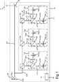
In die Detektionseinrichtung
In diesem Ausführungsbeispiel wird angenommen, dass der Mess-Lichtstrahl LM ein RGB-Lichtstrahl ist, d.h. eine rote, eine grüne und eine blaue Farbkomponente aufweist. Der Mess-Lichtstrahl LM kann, wie gezeigt, insbesondere aus einem Projektionslichtstrahl LP zur Erzeugung eines Projektionsbilds abgezweigt werden (z.B. mittels eines Strahlteilers oder zeitweilig mittels eines Spiegels) oder alternativ sogar der Projektionslichtstrahl sein.In this embodiment, it is assumed that the measuring light beam LM is an RGB light beam, i. has a red, a green and a blue color component. The measuring light beam LM may, as shown, be branched in particular from a projection light beam LP for producing a projection image (for example by means of a beam splitter or temporarily by means of a mirror) or alternatively even the projection light beam.
Der Mess-Lichtstrahl LM durchquert drei Strahlteiler
Im Folgenden wird die Arbeitsweise für jeden einem zugehörigen Strahlteiler
Der Teil-Mess-Lichtstrahl Lr des roten Farbkanals
Der erste Teilstrahl Lr1 durchläuft einen ersten Farbfilter
Wieder zurück zu

Diese Detektionseinrichtung
Der Teil-Mess-Lichtstrahl Lr1 wird zunächst mittels einer Linse
Die Detektionseinrichtung
Obwohl die Erfindung im Detail durch die gezeigten Ausführungsbeispiele näher illustriert und beschrieben wurde, so ist die Erfindung nicht darauf eingeschränkt und andere Variationen können vom Fachmann hieraus abgeleitet werden, ohne den Schutzumfang der Erfindung zu verlassen.Although the invention has been further illustrated and described in detail by the illustrated embodiments, the invention is not so limited and other variations can be derived therefrom by those skilled in the art without departing from the scope of the invention.
Claims (15)
Translated fromGerman


Priority Applications (2)
| Application Number | Priority Date | Filing Date | Title |
|---|---|---|---|
| DE201110079059DE102011079059A1 (en) | 2011-07-13 | 2011-07-13 | DETECTION DEVICE FOR A PROJECTOR |
| PCT/EP2012/060253WO2013007445A1 (en) | 2011-07-13 | 2012-05-31 | Detection device for a projector |
Applications Claiming Priority (1)
| Application Number | Priority Date | Filing Date | Title |
|---|---|---|---|
| DE201110079059DE102011079059A1 (en) | 2011-07-13 | 2011-07-13 | DETECTION DEVICE FOR A PROJECTOR |
Publications (1)
| Publication Number | Publication Date |
|---|---|
| DE102011079059A1true DE102011079059A1 (en) | 2013-01-17 |
Family
ID=46210237
Family Applications (1)
| Application Number | Title | Priority Date | Filing Date |
|---|---|---|---|
| DE201110079059WithdrawnDE102011079059A1 (en) | 2011-07-13 | 2011-07-13 | DETECTION DEVICE FOR A PROJECTOR |
Country Status (2)
| Country | Link |
|---|---|
| DE (1) | DE102011079059A1 (en) |
| WO (1) | WO2013007445A1 (en) |
Cited By (2)
| Publication number | Priority date | Publication date | Assignee | Title |
|---|---|---|---|---|
| DE102013219930A1 (en)* | 2013-10-01 | 2015-04-02 | Osram Gmbh | Lighting device with measuring device and method for operating this lighting device |
| WO2020251678A1 (en)* | 2019-06-13 | 2020-12-17 | Microsoft Technology Licensing, Llc | Monitoring system for improved laser display systems |
Citations (6)
| Publication number | Priority date | Publication date | Assignee | Title |
|---|---|---|---|---|
| DE19951320A1 (en)* | 1999-10-25 | 2001-04-26 | Siemens Ag | Arrangement for detecting an object on and/or in front of a surface comprises a receiving device and a computer to determine reflected waves from the object |
| DE10244821A1 (en)* | 2002-09-26 | 2004-04-01 | Philips Intellectual Property & Standards Gmbh | projection system |
| DE102005054184A1 (en)* | 2005-11-14 | 2007-05-16 | Zeiss Carl Jena Gmbh | Multispectral lighting device |
| US20090027630A1 (en)* | 2007-07-24 | 2009-01-29 | Emiscape, Inc. | One-Way Display Using Color Filter |
| US20090103923A1 (en)* | 2007-10-22 | 2009-04-23 | Kazuhiko Hosomi | Optical Transmitter/Receiver Module |
| US20090237622A1 (en)* | 2008-03-19 | 2009-09-24 | Funai Electric Co., Ltd. | Image display device |
Family Cites Families (6)
| Publication number | Priority date | Publication date | Assignee | Title |
|---|---|---|---|---|
| US4308456A (en)* | 1979-11-19 | 1981-12-29 | Versatile Integrated Modules | Method and apparatus for measuring the frequency of radiation |
| JPH03277929A (en)* | 1990-03-28 | 1991-12-09 | Toshiba Corp | Wavelength measuring device and variable-wavelength semiconductor laser device |
| US6424412B1 (en)* | 2000-08-30 | 2002-07-23 | Sony Corporation | Efficient system and method for detecting and correcting laser misalignment of plural laser beams |
| US7265794B2 (en)* | 2005-09-01 | 2007-09-04 | Texas Instruments Incorporated | Managing the color temperature for a light source array |
| JP2010503169A (en)* | 2006-09-06 | 2010-01-28 | コーニンクレッカ フィリップス エレクトロニクス エヌ ヴィ | Light generation by color mixing |
| CN101755300B (en)* | 2008-05-21 | 2014-02-05 | 松下电器产业株式会社 | Projector |
- 2011
- 2011-07-13DEDE201110079059patent/DE102011079059A1/ennot_activeWithdrawn
- 2012
- 2012-05-31WOPCT/EP2012/060253patent/WO2013007445A1/enactiveApplication Filing
Patent Citations (6)
| Publication number | Priority date | Publication date | Assignee | Title |
|---|---|---|---|---|
| DE19951320A1 (en)* | 1999-10-25 | 2001-04-26 | Siemens Ag | Arrangement for detecting an object on and/or in front of a surface comprises a receiving device and a computer to determine reflected waves from the object |
| DE10244821A1 (en)* | 2002-09-26 | 2004-04-01 | Philips Intellectual Property & Standards Gmbh | projection system |
| DE102005054184A1 (en)* | 2005-11-14 | 2007-05-16 | Zeiss Carl Jena Gmbh | Multispectral lighting device |
| US20090027630A1 (en)* | 2007-07-24 | 2009-01-29 | Emiscape, Inc. | One-Way Display Using Color Filter |
| US20090103923A1 (en)* | 2007-10-22 | 2009-04-23 | Kazuhiko Hosomi | Optical Transmitter/Receiver Module |
| US20090237622A1 (en)* | 2008-03-19 | 2009-09-24 | Funai Electric Co., Ltd. | Image display device |
Cited By (3)
| Publication number | Priority date | Publication date | Assignee | Title |
|---|---|---|---|---|
| DE102013219930A1 (en)* | 2013-10-01 | 2015-04-02 | Osram Gmbh | Lighting device with measuring device and method for operating this lighting device |
| WO2020251678A1 (en)* | 2019-06-13 | 2020-12-17 | Microsoft Technology Licensing, Llc | Monitoring system for improved laser display systems |
| US11233980B2 (en) | 2019-06-13 | 2022-01-25 | Microsoft Technologly Licensing, LLC | Monitoring and correction system for improved laser display systems |
Also Published As
| Publication number | Publication date |
|---|---|
| WO2013007445A1 (en) | 2013-01-17 |
Similar Documents
| Publication | Publication Date | Title |
|---|---|---|
| DE69805645T2 (en) | DISPLAY UNIT WITH A GRID LIGHT VALVE ARRAY AND INTERFEROMETRIC OPTICAL SYSTEM | |
| EP1101362B1 (en) | Device for projecting a colour image | |
| DE19902110C2 (en) | Video projection system for the projection of several single images | |
| DE102011077142B4 (en) | Neighborhood brightness adjustment for uniformity in a tiled display screen | |
| EP1570682B1 (en) | Brightness and colour control of a projection appliance | |
| EP2357831B1 (en) | Method and system for light-beam projection of images on a screen | |
| EP3298345B1 (en) | Camera and method for the three-dimensional measurement and colour measurement of a dental object | |
| DE112015000863T5 (en) | Imaging device, endoscope device and microscope device | |
| DE19607510C2 (en) | LCD projector and method for sharing a light flux | |
| DE69407078T2 (en) | Image projector with autofocus system | |
| WO2007042171A1 (en) | Method for spectral integrated calibration of an image sensor by means of a monochromatic light source | |
| DE102011083718A1 (en) | Confocal spectrometer and method of imaging in a confocal spectrometer | |
| DE102011083726A1 (en) | Confocal spectrometer and method of imaging in a confocal spectrometer | |
| DE4416314C2 (en) | Method and device for recording an image scene and use of the device in a copier | |
| DE10357245A1 (en) | Optical image scanner with moving calibration target | |
| EP0907902A1 (en) | Method of three-dimensional imaging on a large-screen projection surface using a laser projector | |
| WO2018050888A1 (en) | Light microscope | |
| DE112018002190T5 (en) | Image display device and light source device | |
| DE69431399T2 (en) | DICHROITIC IMMERSION SYSTEM FOR VIDEO PROJECTOR WITH A SINGLE PROJECTION LENS | |
| DE102011079059A1 (en) | DETECTION DEVICE FOR A PROJECTOR | |
| DE102019135521A1 (en) | Measuring arrangement, light microscope and measuring method for imaging depth measurement | |
| DE102013105102A1 (en) | Method and device for determining features on objects to be measured | |
| DE102009056178A1 (en) | Image recorder, imaging device and spectroscope for spatially resolved spectroscopy | |
| WO2004105380A1 (en) | Device and method for the multispectral scanning of a color image model | |
| DE102016001663A1 (en) | Recording arrangement for photographic and geometric object data |
Legal Events
| Date | Code | Title | Description |
|---|---|---|---|
| R163 | Identified publications notified | ||
| R081 | Change of applicant/patentee | Owner name:OSRAM GMBH, DE Free format text:FORMER OWNER: OSRAM GESELLSCHAFT MIT BESCHRAENKTER HAFTUNG, 81543 MUENCHEN, DE Effective date:20111212 Owner name:OSRAM GMBH, DE Free format text:FORMER OWNER: OSRAM AG, 81543 MUENCHEN, DE Effective date:20130205 | |
| R081 | Change of applicant/patentee | Owner name:OSRAM GMBH, DE Free format text:FORMER OWNER: OSRAM GMBH, 81543 MUENCHEN, DE Effective date:20130826 | |
| R005 | Application deemed withdrawn due to failure to request examination |