DE102011056589A1 - Gas inlet member of a CVD reactor - Google Patents
Gas inlet member of a CVD reactorDownload PDFInfo
- Publication number
- DE102011056589A1 DE102011056589A1DE102011056589ADE102011056589ADE102011056589A1DE 102011056589 A1DE102011056589 A1DE 102011056589A1DE 102011056589 ADE102011056589 ADE 102011056589ADE 102011056589 ADE102011056589 ADE 102011056589ADE 102011056589 A1DE102011056589 A1DE 102011056589A1
- Authority
- DE
- Germany
- Prior art keywords
- gas
- gas inlet
- outlet plate
- gas outlet
- inlet member
- Prior art date
- Legal status (The legal status is an assumption and is not a legal conclusion. Google has not performed a legal analysis and makes no representation as to the accuracy of the status listed.)
- Pending
Links
- 238000000034methodMethods0.000claimsabstractdescription117
- 238000009826distributionMethods0.000claimsabstractdescription21
- 239000002826coolantSubstances0.000claimsabstractdescription11
- 238000006073displacement reactionMethods0.000claimsdescription10
- 238000010926purgeMethods0.000claimsdescription9
- 238000005496temperingMethods0.000claimsdescription4
- 238000004140cleaningMethods0.000abstractdescription7
- 238000006243chemical reactionMethods0.000abstractdescription4
- 239000007789gasSubstances0.000description325
- 230000003071parasitic effectEffects0.000description7
- 238000005192partitionMethods0.000description7
- 238000011161developmentMethods0.000description6
- 239000000758substrateSubstances0.000description6
- 239000012159carrier gasSubstances0.000description4
- 238000000354decomposition reactionMethods0.000description4
- 230000000694effectsEffects0.000description4
- 239000002184metalSubstances0.000description4
- 230000005855radiationEffects0.000description4
- OKTJSMMVPCPJKN-UHFFFAOYSA-NCarbonChemical compound[C]OKTJSMMVPCPJKN-UHFFFAOYSA-N0.000description3
- 238000001816coolingMethods0.000description3
- 238000005530etchingMethods0.000description3
- 229910002804graphiteInorganic materials0.000description3
- 239000010439graphiteSubstances0.000description3
- 150000004678hydridesChemical class0.000description3
- 210000000056organAnatomy0.000description3
- 150000002902organometallic compoundsChemical class0.000description3
- XYFCBTPGUUZFHI-UHFFFAOYSA-NPhosphineChemical compoundPXYFCBTPGUUZFHI-UHFFFAOYSA-N0.000description2
- 230000015572biosynthetic processEffects0.000description2
- 238000005137deposition processMethods0.000description2
- 238000013461designMethods0.000description2
- 239000000463materialSubstances0.000description2
- 239000010453quartzSubstances0.000description2
- VYPSYNLAJGMNEJ-UHFFFAOYSA-Nsilicon dioxideInorganic materialsO=[Si]=OVYPSYNLAJGMNEJ-UHFFFAOYSA-N0.000description2
- BUHVIAUBTBOHAG-FOYDDCNASA-N(2r,3r,4s,5r)-2-[6-[[2-(3,5-dimethoxyphenyl)-2-(2-methylphenyl)ethyl]amino]purin-9-yl]-5-(hydroxymethyl)oxolane-3,4-diolChemical compoundCOC1=CC(OC)=CC(C(CNC=2C=3N=CN(C=3N=CN=2)[C@H]2[C@@H]([C@H](O)[C@@H](CO)O2)O)C=2C(=CC=CC=2)C)=C1BUHVIAUBTBOHAG-FOYDDCNASA-N0.000description1
- 238000013459approachMethods0.000description1
- RBFQJDQYXXHULB-UHFFFAOYSA-NarsaneChemical compound[AsH3]RBFQJDQYXXHULB-UHFFFAOYSA-N0.000description1
- 239000007795chemical reaction productSubstances0.000description1
- 239000003795chemical substances by applicationSubstances0.000description1
- 239000011248coating agentSubstances0.000description1
- 238000000576coating methodMethods0.000description1
- 238000009833condensationMethods0.000description1
- 230000005494condensationEffects0.000description1
- 239000004020conductorSubstances0.000description1
- 238000010276constructionMethods0.000description1
- 230000008021depositionEffects0.000description1
- 238000010574gas phase reactionMethods0.000description1
- 230000005484gravityEffects0.000description1
- 230000017525heat dissipationEffects0.000description1
- 238000011065in-situ storageMethods0.000description1
- 239000000543intermediateSubstances0.000description1
- 239000007788liquidSubstances0.000description1
- 238000004519manufacturing processMethods0.000description1
- 239000000203mixtureSubstances0.000description1
- 125000002524organometallic groupChemical group0.000description1
- 239000002245particleSubstances0.000description1
- 229910000073phosphorus hydrideInorganic materials0.000description1
- 239000000047productSubstances0.000description1
- 230000000284resting effectEffects0.000description1
- 239000004065semiconductorSubstances0.000description1
- 238000003860storageMethods0.000description1
- 238000007725thermal activationMethods0.000description1
- 238000012546transferMethods0.000description1
- 238000009424underpinningMethods0.000description1
Images


Classifications
- C—CHEMISTRY; METALLURGY
- C23—COATING METALLIC MATERIAL; COATING MATERIAL WITH METALLIC MATERIAL; CHEMICAL SURFACE TREATMENT; DIFFUSION TREATMENT OF METALLIC MATERIAL; COATING BY VACUUM EVAPORATION, BY SPUTTERING, BY ION IMPLANTATION OR BY CHEMICAL VAPOUR DEPOSITION, IN GENERAL; INHIBITING CORROSION OF METALLIC MATERIAL OR INCRUSTATION IN GENERAL
- C23C—COATING METALLIC MATERIAL; COATING MATERIAL WITH METALLIC MATERIAL; SURFACE TREATMENT OF METALLIC MATERIAL BY DIFFUSION INTO THE SURFACE, BY CHEMICAL CONVERSION OR SUBSTITUTION; COATING BY VACUUM EVAPORATION, BY SPUTTERING, BY ION IMPLANTATION OR BY CHEMICAL VAPOUR DEPOSITION, IN GENERAL
- C23C16/00—Chemical coating by decomposition of gaseous compounds, without leaving reaction products of surface material in the coating, i.e. chemical vapour deposition [CVD] processes
- C23C16/44—Chemical coating by decomposition of gaseous compounds, without leaving reaction products of surface material in the coating, i.e. chemical vapour deposition [CVD] processes characterised by the method of coating
- C23C16/455—Chemical coating by decomposition of gaseous compounds, without leaving reaction products of surface material in the coating, i.e. chemical vapour deposition [CVD] processes characterised by the method of coating characterised by the method used for introducing gases into reaction chamber or for modifying gas flows in reaction chamber
- C23C16/45587—Mechanical means for changing the gas flow
- C23C16/45591—Fixed means, e.g. wings, baffles
- C—CHEMISTRY; METALLURGY
- C23—COATING METALLIC MATERIAL; COATING MATERIAL WITH METALLIC MATERIAL; CHEMICAL SURFACE TREATMENT; DIFFUSION TREATMENT OF METALLIC MATERIAL; COATING BY VACUUM EVAPORATION, BY SPUTTERING, BY ION IMPLANTATION OR BY CHEMICAL VAPOUR DEPOSITION, IN GENERAL; INHIBITING CORROSION OF METALLIC MATERIAL OR INCRUSTATION IN GENERAL
- C23C—COATING METALLIC MATERIAL; COATING MATERIAL WITH METALLIC MATERIAL; SURFACE TREATMENT OF METALLIC MATERIAL BY DIFFUSION INTO THE SURFACE, BY CHEMICAL CONVERSION OR SUBSTITUTION; COATING BY VACUUM EVAPORATION, BY SPUTTERING, BY ION IMPLANTATION OR BY CHEMICAL VAPOUR DEPOSITION, IN GENERAL
- C23C16/00—Chemical coating by decomposition of gaseous compounds, without leaving reaction products of surface material in the coating, i.e. chemical vapour deposition [CVD] processes
- C23C16/22—Chemical coating by decomposition of gaseous compounds, without leaving reaction products of surface material in the coating, i.e. chemical vapour deposition [CVD] processes characterised by the deposition of inorganic material, other than metallic material
- C23C16/30—Deposition of compounds, mixtures or solid solutions, e.g. borides, carbides, nitrides
- C23C16/301—AIII BV compounds, where A is Al, Ga, In or Tl and B is N, P, As, Sb or Bi
- C—CHEMISTRY; METALLURGY
- C23—COATING METALLIC MATERIAL; COATING MATERIAL WITH METALLIC MATERIAL; CHEMICAL SURFACE TREATMENT; DIFFUSION TREATMENT OF METALLIC MATERIAL; COATING BY VACUUM EVAPORATION, BY SPUTTERING, BY ION IMPLANTATION OR BY CHEMICAL VAPOUR DEPOSITION, IN GENERAL; INHIBITING CORROSION OF METALLIC MATERIAL OR INCRUSTATION IN GENERAL
- C23C—COATING METALLIC MATERIAL; COATING MATERIAL WITH METALLIC MATERIAL; SURFACE TREATMENT OF METALLIC MATERIAL BY DIFFUSION INTO THE SURFACE, BY CHEMICAL CONVERSION OR SUBSTITUTION; COATING BY VACUUM EVAPORATION, BY SPUTTERING, BY ION IMPLANTATION OR BY CHEMICAL VAPOUR DEPOSITION, IN GENERAL
- C23C16/00—Chemical coating by decomposition of gaseous compounds, without leaving reaction products of surface material in the coating, i.e. chemical vapour deposition [CVD] processes
- C23C16/44—Chemical coating by decomposition of gaseous compounds, without leaving reaction products of surface material in the coating, i.e. chemical vapour deposition [CVD] processes characterised by the method of coating
- C23C16/455—Chemical coating by decomposition of gaseous compounds, without leaving reaction products of surface material in the coating, i.e. chemical vapour deposition [CVD] processes characterised by the method of coating characterised by the method used for introducing gases into reaction chamber or for modifying gas flows in reaction chamber
- C23C16/45563—Gas nozzles
- C23C16/45565—Shower nozzles
- C—CHEMISTRY; METALLURGY
- C23—COATING METALLIC MATERIAL; COATING MATERIAL WITH METALLIC MATERIAL; CHEMICAL SURFACE TREATMENT; DIFFUSION TREATMENT OF METALLIC MATERIAL; COATING BY VACUUM EVAPORATION, BY SPUTTERING, BY ION IMPLANTATION OR BY CHEMICAL VAPOUR DEPOSITION, IN GENERAL; INHIBITING CORROSION OF METALLIC MATERIAL OR INCRUSTATION IN GENERAL
- C23C—COATING METALLIC MATERIAL; COATING MATERIAL WITH METALLIC MATERIAL; SURFACE TREATMENT OF METALLIC MATERIAL BY DIFFUSION INTO THE SURFACE, BY CHEMICAL CONVERSION OR SUBSTITUTION; COATING BY VACUUM EVAPORATION, BY SPUTTERING, BY ION IMPLANTATION OR BY CHEMICAL VAPOUR DEPOSITION, IN GENERAL
- C23C16/00—Chemical coating by decomposition of gaseous compounds, without leaving reaction products of surface material in the coating, i.e. chemical vapour deposition [CVD] processes
- C23C16/44—Chemical coating by decomposition of gaseous compounds, without leaving reaction products of surface material in the coating, i.e. chemical vapour deposition [CVD] processes characterised by the method of coating
- C23C16/455—Chemical coating by decomposition of gaseous compounds, without leaving reaction products of surface material in the coating, i.e. chemical vapour deposition [CVD] processes characterised by the method of coating characterised by the method used for introducing gases into reaction chamber or for modifying gas flows in reaction chamber
- C23C16/45563—Gas nozzles
- C23C16/45572—Cooled nozzles
- C—CHEMISTRY; METALLURGY
- C23—COATING METALLIC MATERIAL; COATING MATERIAL WITH METALLIC MATERIAL; CHEMICAL SURFACE TREATMENT; DIFFUSION TREATMENT OF METALLIC MATERIAL; COATING BY VACUUM EVAPORATION, BY SPUTTERING, BY ION IMPLANTATION OR BY CHEMICAL VAPOUR DEPOSITION, IN GENERAL; INHIBITING CORROSION OF METALLIC MATERIAL OR INCRUSTATION IN GENERAL
- C23C—COATING METALLIC MATERIAL; COATING MATERIAL WITH METALLIC MATERIAL; SURFACE TREATMENT OF METALLIC MATERIAL BY DIFFUSION INTO THE SURFACE, BY CHEMICAL CONVERSION OR SUBSTITUTION; COATING BY VACUUM EVAPORATION, BY SPUTTERING, BY ION IMPLANTATION OR BY CHEMICAL VAPOUR DEPOSITION, IN GENERAL
- C23C16/00—Chemical coating by decomposition of gaseous compounds, without leaving reaction products of surface material in the coating, i.e. chemical vapour deposition [CVD] processes
- C23C16/44—Chemical coating by decomposition of gaseous compounds, without leaving reaction products of surface material in the coating, i.e. chemical vapour deposition [CVD] processes characterised by the method of coating
- C23C16/455—Chemical coating by decomposition of gaseous compounds, without leaving reaction products of surface material in the coating, i.e. chemical vapour deposition [CVD] processes characterised by the method of coating characterised by the method used for introducing gases into reaction chamber or for modifying gas flows in reaction chamber
- C23C16/45563—Gas nozzles
- C23C16/45574—Nozzles for more than one gas
- C—CHEMISTRY; METALLURGY
- C23—COATING METALLIC MATERIAL; COATING MATERIAL WITH METALLIC MATERIAL; CHEMICAL SURFACE TREATMENT; DIFFUSION TREATMENT OF METALLIC MATERIAL; COATING BY VACUUM EVAPORATION, BY SPUTTERING, BY ION IMPLANTATION OR BY CHEMICAL VAPOUR DEPOSITION, IN GENERAL; INHIBITING CORROSION OF METALLIC MATERIAL OR INCRUSTATION IN GENERAL
- C23C—COATING METALLIC MATERIAL; COATING MATERIAL WITH METALLIC MATERIAL; SURFACE TREATMENT OF METALLIC MATERIAL BY DIFFUSION INTO THE SURFACE, BY CHEMICAL CONVERSION OR SUBSTITUTION; COATING BY VACUUM EVAPORATION, BY SPUTTERING, BY ION IMPLANTATION OR BY CHEMICAL VAPOUR DEPOSITION, IN GENERAL
- C23C16/00—Chemical coating by decomposition of gaseous compounds, without leaving reaction products of surface material in the coating, i.e. chemical vapour deposition [CVD] processes
- C23C16/44—Chemical coating by decomposition of gaseous compounds, without leaving reaction products of surface material in the coating, i.e. chemical vapour deposition [CVD] processes characterised by the method of coating
- C23C16/455—Chemical coating by decomposition of gaseous compounds, without leaving reaction products of surface material in the coating, i.e. chemical vapour deposition [CVD] processes characterised by the method of coating characterised by the method used for introducing gases into reaction chamber or for modifying gas flows in reaction chamber
- C23C16/45563—Gas nozzles
- C23C16/45576—Coaxial inlets for each gas
- C—CHEMISTRY; METALLURGY
- C30—CRYSTAL GROWTH
- C30B—SINGLE-CRYSTAL GROWTH; UNIDIRECTIONAL SOLIDIFICATION OF EUTECTIC MATERIAL OR UNIDIRECTIONAL DEMIXING OF EUTECTOID MATERIAL; REFINING BY ZONE-MELTING OF MATERIAL; PRODUCTION OF A HOMOGENEOUS POLYCRYSTALLINE MATERIAL WITH DEFINED STRUCTURE; SINGLE CRYSTALS OR HOMOGENEOUS POLYCRYSTALLINE MATERIAL WITH DEFINED STRUCTURE; AFTER-TREATMENT OF SINGLE CRYSTALS OR A HOMOGENEOUS POLYCRYSTALLINE MATERIAL WITH DEFINED STRUCTURE; APPARATUS THEREFOR
- C30B25/00—Single-crystal growth by chemical reaction of reactive gases, e.g. chemical vapour-deposition growth
- C30B25/02—Epitaxial-layer growth
- C30B25/14—Feed and outlet means for the gases; Modifying the flow of the reactive gases
Landscapes
- Chemical & Material Sciences (AREA)
- General Chemical & Material Sciences (AREA)
- Chemical Kinetics & Catalysis (AREA)
- Engineering & Computer Science (AREA)
- Materials Engineering (AREA)
- Metallurgy (AREA)
- Organic Chemistry (AREA)
- Mechanical Engineering (AREA)
- Crystallography & Structural Chemistry (AREA)
- Inorganic Chemistry (AREA)
- Chemical Vapour Deposition (AREA)
Abstract
Translated fromGerman
Description
Translated fromGermanDie Erfindung betrifft ein Gaseinlassorgan eines CVD-Reaktors mit einem Gaseinlassgehäuse, welches zumindest ein erstes, von einer ersten Zuleitung mit einem ersten Prozessgas speisbares Gasverteilplenum aufweist, welches mit einer Vielzahl von ersten Gasleitungen mit einer mit einem Kühlmittel kühlbaren Gaseinlassgehäusewand verbunden ist, vor welcher Gaseinlassgehäusewand eine Gasauslassplatte mit ersten Öffnungen angeordnet ist, durch die das erste Prozessgas hindurchtreten kann.The invention relates to a gas inlet member of a CVD reactor with a gas inlet housing, which has at least a first, supplied by a first supply line with a first process gas Gasverteilplenum which is connected to a plurality of first gas lines with a coolable with a coolant gas inlet housing wall, in front of which Gaseinlassgehäusewand a gas outlet plate is arranged with first openings through which the first process gas can pass.
Ein Gaseinlassorgan der zuvor beschriebenen Art wird in den
Bei CVD-Reaktoren mit Gaseinlassorganen, bei denen die Prozesskammerdecke von der Gaseinlassgehäusewand selbst gebildet ist, kommt es an der gekühlten Gaseinlassgehäusewand zu parasitärem Wachstum. Dies kann zu einer unerwünschten Partikelbildung innerhalb der Prozesskammer führen. Außerdem können die Mündungen der Gaszuleitungen verstopfen. Dies hat zur Folge, dass die Gaseinlassorgane häufig mechanisch gereinigt werden müssen. Zur Reinigung der Gasaustrittsseite des Gaseinlassorganes muss das gesamte Reaktorgehäuse geöffnet werden.In CVD reactors with gas inlet members in which the process chamber ceiling is formed by the gas inlet housing wall itself, parasitic growth occurs at the cooled gas inlet housing wall. This can lead to undesirable particle formation within the process chamber. In addition, the mouths of the gas supply lines can become clogged. This has the consequence that the gas inlet organs often have to be mechanically cleaned. To clean the gas outlet side of the gas inlet member, the entire reactor housing must be opened.
Der Erfindung liegt daher die Aufgabe zu Grunde, Maßnahmen anzugeben, mit denen die Reinigungszyklen verlängert werden können.The invention is therefore based on the object to specify measures with which the cleaning cycles can be extended.
Die aus dem oben genannten Stand der Technik her bekannte Gasauslassplatte besitzt Öffnungen zum Durchtritt des Prozessgases. Die Gasauslassplatte liegt zwar in berührender Anlage an der gekühlten Gaseinlassgehäusewand. Gleichwohl wird die Gasauslassplatte aber durch Wärmeleitung über das Prozessgas durch die Prozesskammer oder über Wärmestrahlung vom Suszeptor her beheizt. Die Mündungen der Öffnungen der Gasauslassplatte können so eine Temperatur erreichen, bei der sich das durch die Öffnungen hindurchtretende Prozessgas zerlegt. Die Zerlegungsprodukte können im Bereich der Mündung miteinander reagieren. Dies kann auch zu parasitären Reaktionen in der Gasphase führen, wo sich unerwünschte Addukte bilden können.The known from the above-mentioned prior art ago gas outlet plate has openings for the passage of the process gas. Although the gas outlet plate is in contact with the cooled gas inlet housing wall. Nevertheless, however, the gas outlet plate is heated by heat conduction via the process gas through the process chamber or via heat radiation from the susceptor. The mouths of the openings of the gas outlet plate can thus reach a temperature at which breaks down the process gas passing through the openings. The decomposition products can react with one another in the region of the mouth. This can also lead to parasitic reactions in the gas phase, where undesirable adducts can form.
Der Erfindung liegt daher die weitere Aufgabe zu Grunde, Maßnahmen anzugeben, mit denen unerwünschte Vorreaktionen vermindert werden.The invention is therefore based on the further object of specifying measures with which unwanted pre-reactions can be reduced.
Bei einem CVD-Reaktor, bei dem die Prozesskammerdecke unmittelbar gekühlt wird, muss wegen der hohen Wärmeabfuhr eine hohe Wärmeleistung aufgebracht werden, um den Suszeptor auf die gewünschten Prozesstemperaturen aufzuheizen.In a CVD reactor in which the process chamber ceiling is cooled directly, a high heat output must be applied because of the high heat dissipation in order to heat the susceptor to the desired process temperatures.
Der Erfindung liegt damit die weitere Aufgabe zu Grunde, die Energieeffizienz zu erhöhen.The invention is thus based on the further object of increasing energy efficiency.
Bei einem Abscheideprozess, bei dem Hydride, beispielsweise Arsin oder Phosphin verwendet werden, die mit metallorganischen Verbindungen der III. Hauptgruppe in der Prozesskammer zusammen reagieren, haben Feuchtigkeitsrückstände negative Auswirkungen auf das Schichtwachstum.In a deposition process in which hydrides, for example arsine or phosphine are used, with the organometallic compounds of III. Main group in the process chamber react together, moisture residues have negative effects on the layer growth.
Der Erfindung liegt daher die weitere Aufgabe zu Grunde, Maßnahmen anzugeben, mit denen sich die feuchtigkeitsverursachten Effekte vermindern lassen.The invention is therefore based on the further object of specifying measures with which the moisture-caused effects can be reduced.
Zumindest eine dieser Aufgabe wird durch die in den Ansprüchen angegebene Erfindung gelöst.At least one of these objects is achieved by the invention defined in the claims.
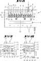
Zunächst und im Wesentlichen wird vorgeschlagen, dass sich die Gasleitungen, durch die ein erstes Prozessgas in die Prozesskammer eingebracht wird über die Gaseinlassgehäusewand fortsetzt. Die Gasleitungen sind bevorzugt Röhrchen, die das erste Gasverteilvolumen durch die von einem Kühlmittel gespülte Kühlkammer hindurch mit der Gaseinlassgehäusewand verbinden. Diese Gasleitungen haben erfindungsgemäß Fortsätze beziehungsweise sind derart verlängert, dass sie bis in die Öffnungen der Gasauslassplatte hineinreichen. Die Gasleitungen können dabei soweit in die Gasauslassplatte hineinreichen, dass ihre Mündungen in der zur Prozesskammer weisenden Oberfläche der Gasauslassplatte liegen. Dabei müssen die Mündungsflächen nicht exakt flächenbündig in der Oberfläche der Gasauslassplatte liegen. Kleinere Stufen insbesondere von der Größenordnung einer Spaltweite um die Gasleitungen sind möglich, gegebenenfalls sogar erwünscht. Ferner ist vorgesehen, dass die Gasauslassplatte gegenüber der gekühlten Gaseinlassgehäusewand thermisch entkoppelt ist. Hierzu ist die Gasauslassplatte bevorzugt durch einen Abstandsfreiraum in Form eines Spaltes von der Gaseinlassgehäusewand beabstandet. Dieser Spalt erstreckt sich bevorzugt über die gesamte Fläche der Gasauslassplatte, so dass die Gasauslassplatte lediglich an ihrem Rand mit dem Gaseinlassorgan verbunden ist.First and foremost, it is proposed that the gas lines, through which a first process gas is introduced into the process chamber, continue via the gas inlet housing wall. The gas lines are preferably tubes which connect the first gas distribution volume through the cooling chamber flushed by a coolant to the gas inlet housing wall. These gas lines according to the invention have extensions or are extended such that they extend into the openings of the gas outlet plate. The gas lines can reach into the gas outlet plate so far that their mouths are in the surface of the gas outlet plate facing the process chamber. The mouth surfaces do not have to lie exactly flush in the surface of the gas outlet plate. Smaller steps in particular of the order of a gap width around the gas lines are possible, if necessary even desirable. It is further provided that the gas outlet plate is thermally decoupled from the cooled gas inlet housing wall. For this purpose, the gas outlet plate is preferably by a clearance clearance in the form of a gap of the Gas inlet housing wall spaced. This gap preferably extends over the entire surface of the gas outlet plate, so that the gas outlet plate is connected only at its edge to the gas inlet member.
In einer Weiterbildung der Erfindung ist vorgesehen, dass mit dem duschkopfartig ausgebildeten Gaseinlassorgan zumindest ein weiteres Prozessgas in die Prozesskammer eingeleitet werden kann. Hierzu bildet das Gaseinlassorgan ein zweites Gasverteilvolumen aus, das ebenfalls mittels Röhrchen, die Gaszuleitungen bilden, mit der Gaseinlassgehäusewand verbunden sind. Die beiden Gasverteilvolumina können übereinander geschichtet angeordnet sein. Die zweiten Gaszuleitungen, durch die das zweite Prozessgas, bei dem es sich bevorzugt um ein Hydrid der V. Hauptgruppe handelt, münden in den Spalt zwischen der Gaseinlassgehäusewand und der Gasauslassplatte. Die Mündung der zweiten Gasleitungen liegen bündig in der Gaseinlassgehäusewand. Die Gasleitungsfortsätze der ersten Gasleitungen, durch die bevorzugt eine metallorganische Verbindung eines Elementes der III. Hauptgruppe in die Prozesskammer eingeleitet wird, liegen bevorzugt bündig in der zur Prozesskammer weisenden Unterseite der Gasauslassplatte. Die Öffnung, durch die die Gasleitungsfortsätze der ersten Gasleitungen ragen, haben vorzugsweise eine größere Öffnungsweite als der Außendurchmesser der Gasleitungsfortsätze, so dass sich um die Gasleitungsfortsätze ein Ringspalt ausbildet, durch den Gas, welches in den Spalt zwischen Gaseinlassgehäusewand und Gasauslassplatte eingebracht wird, hindurchtreten kann.In a further development of the invention, it is provided that at least one further process gas can be introduced into the process chamber with the gas-inlet-type gas inlet element. For this purpose, the gas inlet member forms a second gas distribution volume, which are likewise connected to the gas inlet housing wall by means of tubes which form gas supply lines. The two gas distribution volumes can be arranged stacked one above the other. The second gas supply lines, through which the second process gas, which is preferably a hydride of the V main group, open into the gap between the gas inlet housing wall and the gas outlet plate. The mouth of the second gas lines are flush in the gas inlet housing wall. The gas line extensions of the first gas lines through which preferably an organometallic compound of an element of III. Main group is introduced into the process chamber, are preferably flush in the process chamber facing the bottom of the gas outlet. The opening through which project the gas line extensions of the first gas lines, preferably have a greater opening width than the outer diameter of the gas line extensions, so that forms an annular gap around the gas line extensions, can pass through the gas which is introduced into the gap between the gas inlet housing wall and Gasauslassplatte ,
In einer Weiterbildung der Erfindung ist vorgesehen, dass die Gasauslassplatte weitere Öffnungen aufweist, durch die das in den Spalt gebrachte Gas treten kann. Bei diesem Gas handelt es sich bevorzugt um das zweite Prozessgas, das so in die Prozesskammer eintreten kann. Die dem zweiten Prozessgas zugeordneten Öffnungen der Gasauslassplatte können mit den Mündungen der zweiten Gasleitungen fluchten. Die Röhrchen, die die ersten Gasleitungen ausbilden, sind bevorzugt aus Metall. Die Gasleitungsfortsätze sind materialeinheitlich mit den Röhrchen verbunden. Es handelt sich dabei somit um aus der Gaseinlassgehäusewand vorspringende Abschnitte der die ersten Gasleitungen ausbildenden Metallröhrchen. Zufolge dieser Ausgestaltung sind die Mündungen der ersten Gasleitungen thermisch an den gekühlten Abschnitt des Gaseinlassorgans gekoppelt. Die Mündungen der ersten Gasleitungen werden somit auf Temperaturen gehalten, die unterhalb der Zerlegungstemperatur des ersten Prozessgases sind, das durch die ersten Gasleitungen in die Prozesskammer einströmt. Gegenüber diesen „kalten” Abschnitten der Prozesskammerdecke kann sich die Gasauslassplatte aufheizen. Sie ist thermisch gegenüber dem gekühlten Abschnitt des Gaseinlassorgans entkoppelt und wird durch Wärmeleitung oder durch Wärmestrahlung vom Suszeptor aufgeheizt. Während das erste Prozessgas durch „kalte” Austrittsöffnungen in die Prozesskammer tritt, tritt das zweite Prozessgas durch „heiße” Öffnungen in die Prozesskammer.In a development of the invention, it is provided that the gas outlet plate has further openings through which the gas introduced into the gap can pass. This gas is preferably the second process gas that can enter the process chamber in this way. The second process gas associated openings of the gas outlet plate can be aligned with the mouths of the second gas lines. The tubes that form the first gas lines are preferably made of metal. The gas line extensions are connected to the tubes with the same material. These are thus sections of the metal tubes forming the first gas lines, which project from the gas inlet housing wall. According to this embodiment, the mouths of the first gas lines are thermally coupled to the cooled portion of the gas inlet member. The mouths of the first gas lines are thus maintained at temperatures below the decomposition temperature of the first process gas, which flows through the first gas lines into the process chamber. Opposite these "cold" sections of the process chamber ceiling, the gas outlet plate can heat up. It is thermally decoupled from the cooled portion of the gas inlet member and is heated by conduction or by heat radiation from the susceptor. While the first process gas enters the process chamber through "cold" outlet openings, the second process gas enters the process chamber through "hot" openings.
In einer Weiterbildung der Erfindung, die eine eigenständige Bedeutung besitzt, ist vorgesehen, dass die ersten Zuleitungen in der Gasauslassplatte auf den Eckpunkten gleichseitiger Dreiecke liegen. Hierdurch ergibt sich insgesamt eine hexagonale Anordnung der ersten Zuleitung in der Gasaustrittsebene der Gasauslassplatte. Die zweiten Austrittsöffnungen in der Gasauslassplatte, durch die das zweite Prozessgas in die Prozesskammer eintritt, liegen bevorzugt auf den Mittelpunkten dieser Dreiecke. Demzufolge liegen auch die Mündungen der zweiten Gasleitungen auf den Eckpunkten gleichseitiger Dreiecke. Das zweite Prozessgas kann nicht nur durch diese, ihm zugeordnete Öffnungen der Gasauslassplatte in die Prozesskammer treten. Das zweite Prozessgas kann auch durch den Ringspalt um die Gasleitungsfortsätze in die Prozesskammer eintreten. Durch diese Ringspalte kann aber auch ein Spülgas in die Prozesskammer eingeleitet werden, so dass ein Kontakt zwischen den beiden Prozessgasen in einen Bereich heißerer Gastemperaturen verschoben wird. Zur Einleitung eines Spülgases können die ersten Gasleitungen aber auch konstruktiv weitergebildet sein. Beispielsweise können die ersten Gasleitungen innerhalb eines Rohres mit einem größeren Durchmesser verlaufen, so dass sich um die ersten Gasleitungen ein Ringspalt bildet, durch das ein Spülgas in die Prozesskammer eingleitet wird. Die beiden ineinandergeschachtelten Rohre münden durch die Öffnungen in der Gasauslassplatte in die Prozesskammer. Auch hier kann ein derart ineinandergeschachteltes Röhrchen von einem Ringspalt umgeben sein, durch welches das zweite Prozessgas in die Prozesskammer eingeleitet wird. Es ist aber auch möglich, dass durch den sich um die erste Gasleitung ausbildenden Ringspalt ein weiteres Prozessgas in die Prozesskammer eingeleitet wird.In a further development of the invention, which has an independent meaning, it is provided that the first supply lines in the gas outlet plate lie on the vertices of equilateral triangles. This results overall in a hexagonal arrangement of the first supply line in the gas outlet plane of the gas outlet plate. The second outlet openings in the gas outlet plate, through which the second process gas enters the process chamber, are preferably located at the centers of these triangles. Consequently, the mouths of the second gas lines lie on the vertices of equilateral triangles. The second process gas can not only enter the process chamber through these openings of the gas outlet plate assigned to it. The second process gas can also enter the process chamber through the annular gap around the gas line extensions. Through these annular gaps but also a purge gas can be introduced into the process chamber, so that a contact between the two process gases is shifted to a range of hotter gas temperatures. For the introduction of a purge gas, the first gas lines can also be constructively developed. For example, the first gas lines can run within a tube with a larger diameter, so that forms around the first gas lines an annular gap through which a purge gas is introduced into the process chamber. The two nested tubes open into the process chamber through the openings in the gas outlet plate. Again, such a nested tube may be surrounded by an annular gap through which the second process gas is introduced into the process chamber. However, it is also possible for another process gas to be introduced into the process chamber through the annular gap forming around the first gas line.
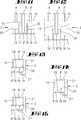
In einer Weiterbildung der Erfindung ist vorgesehen, dass die Gasauslassplatte höhenvariierbar gegenüber der Gaseinlassgehäusewand bzw. dem Suszeptor im Reaktorgehäuse angeordnet ist. Sollen in der Prozesskammer ein oder mehrere auf dem Suszeptor aufliegende Substrate mit einer Schicht beschichtet werden, so befindet sich die Gasauslassplatte in einer Betriebsstellung, in der sie durch einen geringen Abstandsfreiraum von der Gaseinlassgehäusewand getrennt ist. Sie befindet sich in einer thermisch entkoppelten Position gegenüber der Gaseinlassgehäusewand. Die ersten Gasleitungen ragen mit ihren Fortsätzen in die Öffnungen der Gasauslassplatte hinein, wobei die Fortsätze seitlich von der Wandung der Öffnung beabstandet sind. Durch die Fortsätze tritt ein erstes Prozessgas in die Prozesskammer hinein. Durch den Ringspalt zwischen den Fortsätzen und der Öffnungswandung kann das zweite Prozessgas oder ein Spülgas in die Prozesskammer eintreten. Zur Reinigung der Prozesskammer und insbesondere der zur Prozesskammer weisenden Oberfläche der Gasauslassplatte kann in die Prozesskammer ein Ätzgas eingeleitet werden. Es ist aber auch möglich, zusätzlich oder alternativ dazu die Gasauslassplatte in Richtung auf den beheizten Suszeptor zu verlagern und/oder den Abstand zur gekühlten Gaseinlassgehäusewand zu vergrößern. Indem dadurch die Gasauslassplatte näher an die heißere Oberfläche des Suszeptors gebracht wird, lässt sie sich auf eine höhere Temperatur aufheizen, bei der die an der Unterseite der Gasauslassplatte anhaftenden parasitären Beläge entfernt werden können. Zur Vertikalverlagerung kann die Vorrichtung einen Hubmechanismus aufweisen, mit dem der Abstand zwischen Gaseinlassgehäusewand und Gasauslassplatte variierbar ist. In einer Weiterbildung der Erfindung ist die Gasauslassplatte derart an der Unterseite des Gaseinlassorgans befestigt, dass sie in ihrer Erstreckungsrichtung verlagerbar ist. Durch eine derartige Horizontalverlagerbarkeit der Gasauslassplatte lässt sich erreichen, dass die Gaseinleitungsfortsätze von einer Betriebsstellung, in der sie frei in die Öffnungen hineinreichen, in eine andere Betriebsstellung gebracht wird, in der jeweils die Wandung eines gekühlten Gaseinleitungsfortsatzes an der Wandung der Öffnung anliegt. Die Gasauslassplatte ist dadurch in eine Wärmeleitverbindung mit den Gasleitungsfortsätzen bringbar. Mit diesen Maßnahmen ist es möglich, die Gasauslassplatte beim Wachstumsprozess auf Temperaturen unter 450°C, bevorzugt unter 400°C zu halten. Durch eine Modifikation der Lage der Gasauslassplatte gegenüber der Gaseinlassgehäusewand ist es möglich, in einer anschließenden Reinigungsphase die Oberflächentemperatur der zur Prozesskammer weisenden Seite der Gasauslassplatte auf Temperaturen größer 500°C zu bringen. Als besonders bevorzugt wird dabei die Kombination angesehen, in der die Gasauslassplatte nicht nur vertikal, sondern auch horizontal verlagerbar ist. In einer Weiterbildung der Erfindung sind die Öffnungen in der Gasauslassplatte dahingehend modifiziert, dass sie eine in den Abstandsfreiraum ragende Hülse aufweisen. Die Hülse bildet einen Rohrabschnitt, in den teleskopartig die erste Gasleitung hineinragt. Zufolge dieser Ausgestaltung lässt sich die Vertikalposition der Gasauslassplatte über einen relativ großen Bereich variieren, ohne dass die Mündung der Gasleitungsfortsätze aus der ihnen zugeordneten Hülse heraustritt und frei in den Abstandsfreiraum hineinragt. Aus der Mündung der ersten Gasleitung heraustretende Prozessgase geraten somit auch bei einer Vergrößerung des Abstandes zwischen Gaseinlassgehäusewand und Gasauslassplatte nicht in den Abstandsfreiraum. Eine Mischung der Prozessgase findet somit erst innerhalb der durch die Hülse verlängerten Öffnung statt. Das zweite Prozessgas tritt durch den Ringspalt zwischen Hülseninnenwand und Außenwandung des Gasleitungsfortsatzes in die Öffnung hinein. In einer Weiterbildung der Erfindung ist vorgesehen, dass die Wandungen der Öffnung profiliert sind. Beispielsweise können die Öffnungen der Gasauslassplatte Fasen oder Senkungen aufweisen. Diese Profilierungen können sich auf der von der Prozesskammer wegweisenden Seite der Gasauslassplatte befinden. Derartige Fasen vereinfachen darüber hinaus auch die Montage, da sie einen Selbstzentriereffekt bewirken. Liegen Toleranzfehler vor, minimieren die Fasen eventuelle thermische Brücken zwischen den Gasleitungsfortsätzen und dem Öffnungsrand. In diesem Fall kann es vorteilhaft sein, wenn die Profilierungen, also die Fasen bzw. Senkungen auf der zur Prozesskammer weisenden Seite der Gasauslassplatte angeordnet sind. Hierdurch vermindert sich auch die Wachstumsrate an der Kante, so dass die Betriebszeit zwischen zwei Reinigungsschritten verlängert wird. Schließlich ist es von Vorteil, wenn der Querschnitt der Öffnung einen unrunden Verlauf hat, insbesondere in die Öffnung hineinragende Vorsprünge aufweist, die bei einer Horizontalverlagerung der Gasauslassplatte in einen thermischen Kontakt mit den Gasleitfortsätzen treten können.In one embodiment of the invention, it is provided that the gas outlet plate is arranged variable in height relative to the gas inlet housing wall or the susceptor in the reactor housing. If one or more substrates resting on the susceptor are to be coated with a layer in the process chamber, then the gas outlet plate is in an operating position in which it is separated from the gas inlet housing wall by a small clearance. It is in a thermally decoupled position opposite the gas inlet housing wall. The first gas lines protrude with their extensions into the openings of the gas outlet plate, wherein the projections are laterally spaced from the wall of the opening. By the extensions enters a first process gas into the process chamber. Through the annular gap between the extensions and the opening wall, the second process gas or a purge gas can enter the process chamber. For cleaning the process chamber and in particular the surface of the gas outlet plate facing the process chamber, an etching gas can be introduced into the process chamber. However, it is also possible, additionally or alternatively, to displace the gas outlet plate in the direction of the heated susceptor and / or to increase the distance to the cooled gas inlet housing wall. By thereby bringing the gas outlet plate closer to the hotter surface of the susceptor, it can be heated to a higher temperature at which the parasitic deposits adhering to the underside of the gas outlet plate can be removed. For vertical displacement, the device may comprise a lifting mechanism, with which the distance between the gas inlet housing wall and the gas outlet plate is variable. In a further development of the invention, the gas outlet plate is fastened to the underside of the gas inlet member such that it can be displaced in its direction of extent. Such a horizontal displaceability of the gas outlet plate makes it possible to bring the gas introduction extensions from an operating position in which they extend freely into the openings into another operating position in which the wall of a cooled gas introduction extension bears against the wall of the opening. The gas outlet plate can thereby be brought into a heat conduction connection with the gas line extensions. With these measures, it is possible to keep the gas outlet plate in the growth process to temperatures below 450 ° C, preferably below 400 ° C. By modifying the position of the gas outlet plate relative to the gas inlet housing wall, it is possible to bring the surface temperature of the side of the gas outlet plate facing the process chamber to temperatures greater than 500 ° C. in a subsequent cleaning phase. The combination in which the gas outlet plate can be displaced not only vertically but also horizontally is considered to be particularly preferred. In a development of the invention, the openings in the gas outlet plate are modified in such a way that they have a sleeve protruding into the clearance. The sleeve forms a pipe section into which the first gas line protrudes in a telescopic manner. As a result of this configuration, the vertical position of the gas outlet plate can be varied over a relatively large range without the mouth of the gas line extensions emerging from the sleeve assigned to it and protruding freely into the clearance. Process gases which emerge from the mouth of the first gas line therefore do not enter the clearance space even when the distance between the gas inlet housing wall and the gas outlet plate increases. A mixture of the process gases thus takes place only within the extended through the sleeve opening. The second process gas enters the opening through the annular gap between the inner wall of the sleeve and the outer wall of the gas line extension. In one embodiment of the invention it is provided that the walls of the opening are profiled. For example, the openings of the gas outlet plate may have chamfers or countersinks. These profilings can be located on the side of the gas outlet plate pointing away from the process chamber. Moreover, such chamfers also simplify assembly, as they cause a self-centering effect. If tolerance errors exist, the chamfers minimize any thermal bridges between the gas line extensions and the opening edge. In this case, it may be advantageous if the profilings, that is to say the chamfers or depressions, are arranged on the side of the gas outlet plate facing the process chamber. This also reduces the growth rate at the edge, so that the operating time between two cleaning steps is extended. Finally, it is advantageous if the cross-section of the opening has a non-circular course, in particular in the opening protruding projections, which can occur in a horizontal displacement of the gas outlet plate in thermal contact with the Gasleitfortsätzen.
Ausführungsbeispiele der Erfindung werden nachfolgend anhand beigefügter Zeichnungen erläutert. Es zeigen:Embodiments of the invention are explained below with reference to accompanying drawings. Show it:
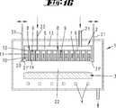
Der erfindungsgemäße CVD-Reaktor besitzt ein nicht dargestelltes Gasbevorratungs- und Dosiersystem, in dem die Prozessgase mit Trägergasen gemischt werden und durch Leitungen den CVD-Reaktor zugeführt werden. In der
Unmittelbar oberhalb der Gaseinlassgehäusewand
Unterhalb der Gaseinlassgehäusewand
Die ebenfalls von Röhrchen ausgebildeten ersten Gasleitungen
Die Gasauslassplatte
Die Gasauslassplatte
Die Öffnungen
Die Gasauslassplatte
Die Zwischenwand
Bei dem in den
Die metallorganischen Komponenten treten durch die ersten Gasleitungen
Mit der erfindungsgemäßen Ausgestaltung des Gaseinlassorgans
Da die Gaseinlassgehäusewand
Bei dem in der
Die in den Zeichnungen 1 bis 4 lediglich in einem vereinfachten Querschnitt dargestellten Gasleitungen liegen in einer bevorzugten Ausgestaltung nicht in einer gemeinsamen Querschnittsebene.The gas lines shown in the
Aus der
Die Öffnungen
Während bei den in den
Zufolge des aus dem Ringspalt
Das in der
Je nach Höhe H des Abstandsfreiraum
Das Maß der Höhe H des Abstandsfreiraumes
Bei dem in den
Das in der
Das in der
Bei dem in der
Das in der
Die
Die
Alle offenbarten Merkmale sind (für sich) erfindungswesentlich. In die Offenbarung der Anmeldung wird hiermit auch der Offenbarungsinhalt der zugehörigen/beigefügten Prioritätsunterlagen (Abschrift der Voranmeldung) vollinhaltlich mit einbezogen, auch zu dem Zweck, Merkmale dieser Unterlagen in Ansprüche vorliegender Anmeldung mit aufzunehmen. Die Unteransprüche charakterisieren in ihrer fakultativ nebengeordneten Fassung eigenständige erfinderische Weiterbildung des Standes der Technik, insbesondere um auf Basis dieser Ansprüche Teilanmeldungen vorzunehmen.All disclosed features are essential to the invention. The disclosure of the associated / attached priority documents (copy of the prior application) is hereby also incorporated in full in the disclosure of the application, also for the purpose of including features of these documents in claims of the present application. The subclaims characterize in their optional sibling version independent inventive development of the prior art, in particular to make on the basis of these claims divisional applications.
BezugszeichenlisteLIST OF REFERENCE NUMBERS
- 11
- Reaktorgehäusereactor housing
- 22
- GaseinlassorganGas inlet element
- 33
- Suszeptorsusceptor
- 44
- Heizungheater
- 55
- erstes Gasverteilvolumenfirst gas distribution volume
- 66
- zweites Gasverteilvolumensecond gas distribution volume
- 77
- KühlmittelkammerCoolant chamber
- 88th
- erste Gasleitungfirst gas line
- 8'8th'
- Mündungmuzzle
- 99
- zweite Gasleitungsecond gas line
- 9'9 '
- Mündungmuzzle
- 1010
- GaseinlassgehäusewandGas inlet housing wall
- 1111
- Zwischenwandpartition
- 1212
- Zwischenwandpartition
- 1313
- GaseinlassgehäusewandGas inlet housing wall
- 1414
- Gasauslassplattegas outlet
- 1515
- GasleitungsfortsatzGas line extension
- 1616
- Öffnungopening
- 1717
- Ringspaltannular gap
- 1818
- Öffnungopening
- 1919
- Temperierkanaltempering
- 2020
- AbstandsfreiraumDistance space
- 2121
- Zuleitungsupply
- 2222
- Prozesskammerprocess chamber
- 2323
- Zuleitungsupply
- 2424
- Zwischenwandpartition
- 2525
- Gasverteilvolumengas distribution volume
- 2626
- Spülgasleitungpurge gas line
- 2727
- Rohrpipe
- 2828
- Profilierungprofiling
- 2929
- Profilierungprofiling
- 3030
- Hülseshell
- 3131
- Verlagerungsmitteldisplacement means
- 31'31 '
- Hakenhook
- 3232
- Vorsprunghead Start
- aa
- Kantenlängeedge length
- HH
- Höheheight
ZITATE ENTHALTEN IN DER BESCHREIBUNG QUOTES INCLUDE IN THE DESCRIPTION
Diese Liste der vom Anmelder aufgeführten Dokumente wurde automatisiert erzeugt und ist ausschließlich zur besseren Information des Lesers aufgenommen. Die Liste ist nicht Bestandteil der deutschen Patent- bzw. Gebrauchsmusteranmeldung. Das DPMA übernimmt keinerlei Haftung für etwaige Fehler oder Auslassungen.This list of the documents listed by the applicant has been generated automatically and is included solely for the better information of the reader. The list is not part of the German patent or utility model application. The DPMA assumes no liability for any errors or omissions.
Zitierte PatentliteraturCited patent literature
- DE 102006018515 A1[0002]DE 102006018515 A1[0002]
Claims (17)
Translated fromGermanPriority Applications (7)
| Application Number | Priority Date | Filing Date | Title |
|---|---|---|---|
| DE102011056589ADE102011056589A1 (en) | 2011-07-12 | 2011-12-19 | Gas inlet member of a CVD reactor |
| EP12734895.1AEP2732069B1 (en) | 2011-07-12 | 2012-07-05 | Gas inlet member of a cvd reactor |
| PCT/EP2012/063072WO2013007580A1 (en) | 2011-07-12 | 2012-07-05 | Gas inlet member of a cvd reactor |
| KR1020147003712AKR102009918B1 (en) | 2011-07-12 | 2012-07-05 | Gas inlet member of a cvd reactor |
| CN201280033705.2ACN103649369B (en) | 2011-07-12 | 2012-07-05 | The admission gear of CVD reactor |
| US14/232,246US9587312B2 (en) | 2011-07-12 | 2012-07-05 | Gas inlet member of a CVD reactor |
| TW101124883ATWI548774B (en) | 2011-07-12 | 2012-07-11 | Air intake mechanism of CVD reactor |
Applications Claiming Priority (3)
| Application Number | Priority Date | Filing Date | Title |
|---|---|---|---|
| DE102011051778.2 | 2011-07-12 | ||
| DE102011051778 | 2011-07-12 | ||
| DE102011056589ADE102011056589A1 (en) | 2011-07-12 | 2011-12-19 | Gas inlet member of a CVD reactor |
Publications (1)
| Publication Number | Publication Date |
|---|---|
| DE102011056589A1true DE102011056589A1 (en) | 2013-01-17 |
Family
ID=47425389
Family Applications (1)
| Application Number | Title | Priority Date | Filing Date |
|---|---|---|---|
| DE102011056589APendingDE102011056589A1 (en) | 2011-07-12 | 2011-12-19 | Gas inlet member of a CVD reactor |
Country Status (7)
| Country | Link |
|---|---|
| US (1) | US9587312B2 (en) |
| EP (1) | EP2732069B1 (en) |
| KR (1) | KR102009918B1 (en) |
| CN (1) | CN103649369B (en) |
| DE (1) | DE102011056589A1 (en) |
| TW (1) | TWI548774B (en) |
| WO (1) | WO2013007580A1 (en) |
Cited By (7)
| Publication number | Priority date | Publication date | Assignee | Title |
|---|---|---|---|---|
| DE102016115614A1 (en) | 2016-08-23 | 2018-03-01 | Aixtron Se | Susceptor for a CVD reactor |
| DE102017100725A1 (en)* | 2016-09-09 | 2018-03-15 | Aixtron Se | CVD reactor and method for cleaning a CVD reactor |
| DE102019119019A1 (en)* | 2019-07-12 | 2021-01-14 | Aixtron Se | Gas inlet element for a CVD reactor |
| WO2021089425A1 (en) | 2019-11-05 | 2021-05-14 | Aixtron Se | Method for depositing a two-dimensional coating and cvd reactor |
| WO2021089424A1 (en) | 2019-11-05 | 2021-05-14 | Aixtron Se | Use of a cvd reactor for depositing two-dimensional layers |
| JP2021116474A (en)* | 2020-01-22 | 2021-08-10 | イーキューテックプラス株式会社 | Radical unit that injects both precursor and reaction gas and ALD device including it |
| DE102021114868A1 (en) | 2021-06-09 | 2022-12-15 | Aixtron Se | Gas inlet element for a CVD reactor |
Families Citing this family (31)
| Publication number | Priority date | Publication date | Assignee | Title |
|---|---|---|---|---|
| WO2011044451A2 (en)* | 2009-10-09 | 2011-04-14 | Applied Materials, Inc. | Multi-gas centrally cooled showerhead design |
| DE102011056589A1 (en)* | 2011-07-12 | 2013-01-17 | Aixtron Se | Gas inlet member of a CVD reactor |
| US10316409B2 (en) | 2012-12-21 | 2019-06-11 | Novellus Systems, Inc. | Radical source design for remote plasma atomic layer deposition |
| CN103060775B (en)* | 2013-01-30 | 2014-12-03 | 中国科学院苏州纳米技术与纳米仿生研究所 | Polyhedron funnel type air inlet unit for CVD (chemical vapor deposition) equipment and CVD equipment |
| US20140235069A1 (en)* | 2013-02-15 | 2014-08-21 | Novellus Systems, Inc. | Multi-plenum showerhead with temperature control |
| KR102451499B1 (en)* | 2014-05-16 | 2022-10-06 | 어플라이드 머티어리얼스, 인코포레이티드 | Showerhead design |
| DE102014117492A1 (en)* | 2014-11-28 | 2016-06-02 | Aixtron Se | Device for depositing a layer on a substrate |
| US10023959B2 (en) | 2015-05-26 | 2018-07-17 | Lam Research Corporation | Anti-transient showerhead |
| US9748113B2 (en) | 2015-07-30 | 2017-08-29 | Veeco Intruments Inc. | Method and apparatus for controlled dopant incorporation and activation in a chemical vapor deposition system |
| US10604841B2 (en) | 2016-12-14 | 2020-03-31 | Lam Research Corporation | Integrated showerhead with thermal control for delivering radical and precursor gas to a downstream chamber to enable remote plasma film deposition |
| KR102369676B1 (en) | 2017-04-10 | 2022-03-04 | 삼성디스플레이 주식회사 | Apparatus and method for manufacturing a display apparatus |
| JP7256135B2 (en)* | 2017-06-23 | 2023-04-11 | メルク パテント ゲゼルシャフト ミット ベシュレンクテル ハフツング | Atomic layer deposition method for selective film growth |
| WO2019113478A1 (en) | 2017-12-08 | 2019-06-13 | Lam Research Corporation | Integrated showerhead with improved hole pattern for delivering radical and precursor gas to a downstream chamber to enable remote plasma film deposition |
| US11189502B2 (en)* | 2018-04-08 | 2021-11-30 | Applied Materials, Inc. | Showerhead with interlaced gas feed and removal and methods of use |
| US10943768B2 (en)* | 2018-04-20 | 2021-03-09 | Applied Materials, Inc. | Modular high-frequency source with integrated gas distribution |
| KR102516885B1 (en)* | 2018-05-10 | 2023-03-30 | 삼성전자주식회사 | Deposition equipment and method of fabricating semiconductor device using the same |
| KR102576220B1 (en)* | 2018-06-22 | 2023-09-07 | 삼성디스플레이 주식회사 | Thin Film Processing Appartus and Method |
| DE102018126617A1 (en) | 2018-10-25 | 2020-04-30 | Aixtron Se | Screen plate for a CVD reactor |
| DE102018130139A1 (en)* | 2018-11-28 | 2020-05-28 | Aixtron Se | Gas inlet device for a CVD reactor |
| DE102018130859A1 (en) | 2018-12-04 | 2020-06-04 | Aixtron Se | CVD reactor with a gas inlet element covered by a screen plate arrangement |
| KR102208609B1 (en)* | 2018-12-28 | 2021-01-28 | (주)에스테크 | Shower head for chemical vapor deposition and depositing apparatus using the same |
| WO2020163074A1 (en)* | 2019-02-05 | 2020-08-13 | Applied Materials, Inc. | Multi channel splitter spool |
| CN113396240A (en)* | 2019-03-11 | 2021-09-14 | 应用材料公司 | Lid assembly apparatus and method for substrate processing chamber |
| CN110004433B (en)* | 2019-05-10 | 2024-03-22 | 普乐新能源(蚌埠)有限公司 | Air supplementing device of low-pressure chemical vapor deposition vacuum tube furnace |
| US11225716B2 (en)* | 2019-11-27 | 2022-01-18 | Tokyo Electron Limited | Internally cooled multi-hole injectors for delivery of process chemicals |
| DE102020103946A1 (en) | 2020-02-14 | 2021-08-19 | AIXTRON Ltd. | Gas inlet device for a CVD reactor |
| KR20210150978A (en)* | 2020-06-03 | 2021-12-13 | 에이에스엠 아이피 홀딩 비.브이. | Shower plate, substrate treatment device, and substrate treatment method |
| CN114402425B (en)* | 2020-08-18 | 2025-08-15 | 玛特森技术公司 | Rapid thermal processing system with cooling system |
| CN114686855B (en)* | 2022-04-13 | 2023-11-14 | 无锡先为科技有限公司 | Nozzle device and film forming apparatus |
| CN115786886A (en)* | 2022-11-16 | 2023-03-14 | 鹏城微纳技术(沈阳)有限公司 | Gas disc and PECVD coating equipment |
| CN119320939B (en)* | 2024-12-19 | 2025-04-29 | 东领科技装备有限公司 | A nozzle assembly for atomic layer deposition |
Citations (8)
| Publication number | Priority date | Publication date | Assignee | Title |
|---|---|---|---|---|
| DE69706248T2 (en)* | 1996-07-24 | 2002-03-21 | Applied Materials Inc | Gas flow control for multiple zones in a process chamber |
| US6544341B1 (en)* | 1998-09-03 | 2003-04-08 | Cvc Products, Inc. | System for fabricating a device on a substrate with a process gas |
| DE10320597A1 (en)* | 2003-04-30 | 2004-12-02 | Aixtron Ag | Method and device for depositing semiconductor layers with two process gases, one of which is preconditioned |
| US20060021574A1 (en)* | 2004-08-02 | 2006-02-02 | Veeco Instruments Inc. | Multi-gas distribution injector for chemical vapor deposition reactors |
| US20060263522A1 (en)* | 2005-05-19 | 2006-11-23 | Piezonics Co., Ltd. | Apparatus for chemical vapor deposition (CVD) with showerhead and method thereof |
| DE102006018515A1 (en) | 2006-04-21 | 2007-10-25 | Aixtron Ag | CVD reactor with lowerable process chamber ceiling |
| US20090169744A1 (en)* | 2006-09-16 | 2009-07-02 | Piezonics Co., Ltd | Apparatus of chemical vapor deposition with a showerhead regulating injection velocity of reactive gases postively and method thereof |
| US7976631B2 (en)* | 2007-10-16 | 2011-07-12 | Applied Materials, Inc. | Multi-gas straight channel showerhead |
Family Cites Families (39)
| Publication number | Priority date | Publication date | Assignee | Title |
|---|---|---|---|---|
| GB9411911D0 (en)* | 1994-06-14 | 1994-08-03 | Swan Thomas & Co Ltd | Improvements in or relating to chemical vapour deposition |
| US5670218A (en)* | 1995-10-04 | 1997-09-23 | Hyundai Electronics Industries Co., Ltd. | Method for forming ferroelectric thin film and apparatus therefor |
| US6565661B1 (en)* | 1999-06-04 | 2003-05-20 | Simplus Systems Corporation | High flow conductance and high thermal conductance showerhead system and method |
| KR100378871B1 (en)* | 2000-02-16 | 2003-04-07 | 주식회사 아펙스 | showerhead apparatus for radical assisted deposition |
| JP3924483B2 (en)* | 2001-03-19 | 2007-06-06 | アイピーエス リミテッド | Chemical vapor deposition equipment |
| US7018940B2 (en)* | 2002-12-30 | 2006-03-28 | Genus, Inc. | Method and apparatus for providing uniform gas delivery to substrates in CVD and PECVD processes |
| JP4306403B2 (en)* | 2003-10-23 | 2009-08-05 | 東京エレクトロン株式会社 | Shower head structure and film forming apparatus using the same |
| KR100513920B1 (en)* | 2003-10-31 | 2005-09-08 | 주식회사 시스넥스 | Chemical vapor deposition unit |
| DE102004009772A1 (en)* | 2004-02-28 | 2005-09-15 | Aixtron Ag | CVD reactor with process chamber height stabilization |
| CN1292092C (en)* | 2004-04-01 | 2006-12-27 | 南昌大学 | Bilayer inlet gas spray nozzle in use for metal-organic chemical vapor deposition device |
| US7785672B2 (en)* | 2004-04-20 | 2010-08-31 | Applied Materials, Inc. | Method of controlling the film properties of PECVD-deposited thin films |
| US8328939B2 (en)* | 2004-05-12 | 2012-12-11 | Applied Materials, Inc. | Diffuser plate with slit valve compensation |
| JP4451221B2 (en)* | 2004-06-04 | 2010-04-14 | 東京エレクトロン株式会社 | Gas processing apparatus and film forming apparatus |
| DE102005055468A1 (en)* | 2005-11-22 | 2007-05-24 | Aixtron Ag | Coating one or more substrates comprises supplying gases to process chamber via chambers with gas outlet openings |
| JP4344949B2 (en)* | 2005-12-27 | 2009-10-14 | セイコーエプソン株式会社 | Shower head, film forming apparatus including shower head, and method for manufacturing ferroelectric film |
| JP2007191792A (en)* | 2006-01-19 | 2007-08-02 | Atto Co Ltd | Gas separation type showerhead |
| US7674352B2 (en)* | 2006-11-28 | 2010-03-09 | Applied Materials, Inc. | System and method for depositing a gaseous mixture onto a substrate surface using a showerhead apparatus |
| DE102007026349A1 (en)* | 2007-06-06 | 2008-12-11 | Aixtron Ag | From a large number of diffusion-welded panes of existing gas distributors |
| US20080317973A1 (en)* | 2007-06-22 | 2008-12-25 | White John M | Diffuser support |
| US20090071403A1 (en)* | 2007-09-19 | 2009-03-19 | Soo Young Choi | Pecvd process chamber with cooled backing plate |
| KR101064210B1 (en)* | 2009-06-01 | 2011-09-14 | 한국생산기술연구원 | Shower head for membrane deposition vacuum equipment |
| KR101062462B1 (en)* | 2009-07-28 | 2011-09-05 | 엘아이지에이디피 주식회사 | Shower head and chemical vapor deposition apparatus comprising the same |
| US20110030615A1 (en)* | 2009-08-04 | 2011-02-10 | Applied Materials, Inc. | Method and apparatus for dry cleaning a cooled showerhead |
| US20110117728A1 (en)* | 2009-08-27 | 2011-05-19 | Applied Materials, Inc. | Method of decontamination of process chamber after in-situ chamber clean |
| CN102021530A (en)* | 2009-09-11 | 2011-04-20 | 甘志银 | Reaction chamber of multiple-gas coupling metal metallorganic chemical vapor deposition equipment |
| WO2011044451A2 (en)* | 2009-10-09 | 2011-04-14 | Applied Materials, Inc. | Multi-gas centrally cooled showerhead design |
| US20110256692A1 (en)* | 2010-04-14 | 2011-10-20 | Applied Materials, Inc. | Multiple precursor concentric delivery showerhead |
| WO2011159690A2 (en)* | 2010-06-15 | 2011-12-22 | Applied Materials, Inc. | Multiple precursor showerhead with by-pass ports |
| US8910644B2 (en)* | 2010-06-18 | 2014-12-16 | Applied Materials, Inc. | Method and apparatus for inducing turbulent flow of a processing chamber cleaning gas |
| US20120000490A1 (en)* | 2010-07-01 | 2012-01-05 | Applied Materials, Inc. | Methods for enhanced processing chamber cleaning |
| US8721791B2 (en)* | 2010-07-28 | 2014-05-13 | Applied Materials, Inc. | Showerhead support structure for improved gas flow |
| CN101914761B (en)* | 2010-08-16 | 2012-04-25 | 江苏中晟半导体设备有限公司 | Device for controlling delivery and uniform distribution of reaction gases in MOCVD reaction chamber |
| US20120052216A1 (en)* | 2010-08-27 | 2012-03-01 | Applied Materials, Inc. | Gas distribution showerhead with high emissivity surface |
| US20120227665A1 (en)* | 2011-03-11 | 2012-09-13 | Applied Materials, Inc. | Apparatus for monitoring and controlling substrate temperature |
| TWI534291B (en)* | 2011-03-18 | 2016-05-21 | 應用材料股份有限公司 | Showerhead assembly |
| DE102011056589A1 (en)* | 2011-07-12 | 2013-01-17 | Aixtron Se | Gas inlet member of a CVD reactor |
| US8960235B2 (en)* | 2011-10-28 | 2015-02-24 | Applied Materials, Inc. | Gas dispersion apparatus |
| CN103388132B (en)* | 2012-05-11 | 2015-11-25 | 中微半导体设备(上海)有限公司 | Gas shower head, its manufacturing method and thin film growth reactor |
| US9343293B2 (en)* | 2013-04-04 | 2016-05-17 | Applied Materials, Inc. | Flowable silicon—carbon—oxygen layers for semiconductor processing |
- 2011
- 2011-12-19DEDE102011056589Apatent/DE102011056589A1/enactivePending
- 2012
- 2012-07-05WOPCT/EP2012/063072patent/WO2013007580A1/enactiveApplication Filing
- 2012-07-05KRKR1020147003712Apatent/KR102009918B1/enactiveActive
- 2012-07-05CNCN201280033705.2Apatent/CN103649369B/enactiveActive
- 2012-07-05EPEP12734895.1Apatent/EP2732069B1/enactiveActive
- 2012-07-05USUS14/232,246patent/US9587312B2/enactiveActive
- 2012-07-11TWTW101124883Apatent/TWI548774B/enactive
Patent Citations (8)
| Publication number | Priority date | Publication date | Assignee | Title |
|---|---|---|---|---|
| DE69706248T2 (en)* | 1996-07-24 | 2002-03-21 | Applied Materials Inc | Gas flow control for multiple zones in a process chamber |
| US6544341B1 (en)* | 1998-09-03 | 2003-04-08 | Cvc Products, Inc. | System for fabricating a device on a substrate with a process gas |
| DE10320597A1 (en)* | 2003-04-30 | 2004-12-02 | Aixtron Ag | Method and device for depositing semiconductor layers with two process gases, one of which is preconditioned |
| US20060021574A1 (en)* | 2004-08-02 | 2006-02-02 | Veeco Instruments Inc. | Multi-gas distribution injector for chemical vapor deposition reactors |
| US20060263522A1 (en)* | 2005-05-19 | 2006-11-23 | Piezonics Co., Ltd. | Apparatus for chemical vapor deposition (CVD) with showerhead and method thereof |
| DE102006018515A1 (en) | 2006-04-21 | 2007-10-25 | Aixtron Ag | CVD reactor with lowerable process chamber ceiling |
| US20090169744A1 (en)* | 2006-09-16 | 2009-07-02 | Piezonics Co., Ltd | Apparatus of chemical vapor deposition with a showerhead regulating injection velocity of reactive gases postively and method thereof |
| US7976631B2 (en)* | 2007-10-16 | 2011-07-12 | Applied Materials, Inc. | Multi-gas straight channel showerhead |
Cited By (11)
| Publication number | Priority date | Publication date | Assignee | Title |
|---|---|---|---|---|
| DE102016115614A1 (en) | 2016-08-23 | 2018-03-01 | Aixtron Se | Susceptor for a CVD reactor |
| WO2018037014A1 (en) | 2016-08-23 | 2018-03-01 | Aixtron Se | Susceptor for a chemical vapour deposition reactor |
| US11168410B2 (en) | 2016-08-23 | 2021-11-09 | Aixtron Se | Susceptor for a chemical vapour deposition reactor |
| DE102017100725A1 (en)* | 2016-09-09 | 2018-03-15 | Aixtron Se | CVD reactor and method for cleaning a CVD reactor |
| DE102019119019A1 (en)* | 2019-07-12 | 2021-01-14 | Aixtron Se | Gas inlet element for a CVD reactor |
| WO2021089425A1 (en) | 2019-11-05 | 2021-05-14 | Aixtron Se | Method for depositing a two-dimensional coating and cvd reactor |
| WO2021089424A1 (en) | 2019-11-05 | 2021-05-14 | Aixtron Se | Use of a cvd reactor for depositing two-dimensional layers |
| JP2021116474A (en)* | 2020-01-22 | 2021-08-10 | イーキューテックプラス株式会社 | Radical unit that injects both precursor and reaction gas and ALD device including it |
| JP7133240B2 (en) | 2020-01-22 | 2022-09-08 | イーキューテックプラス株式会社 | Radical unit for injecting precursor and reaction gas together, and ALD apparatus including the same |
| DE102021114868A1 (en) | 2021-06-09 | 2022-12-15 | Aixtron Se | Gas inlet element for a CVD reactor |
| WO2022258446A1 (en) | 2021-06-09 | 2022-12-15 | Aixtron Se | Gas-inlet element for a cvd reactor |
Also Published As
| Publication number | Publication date |
|---|---|
| EP2732069B1 (en) | 2020-11-04 |
| US9587312B2 (en) | 2017-03-07 |
| US20150007771A1 (en) | 2015-01-08 |
| TW201309842A (en) | 2013-03-01 |
| KR20140061401A (en) | 2014-05-21 |
| EP2732069A1 (en) | 2014-05-21 |
| WO2013007580A1 (en) | 2013-01-17 |
| CN103649369A (en) | 2014-03-19 |
| KR102009918B1 (en) | 2019-10-23 |
| TWI548774B (en) | 2016-09-11 |
| CN103649369B (en) | 2015-12-02 |
Similar Documents
| Publication | Publication Date | Title |
|---|---|---|
| DE102011056589A1 (en) | Gas inlet member of a CVD reactor | |
| EP2408952B1 (en) | Mocvd reactor having a ceiling panel coupled locally differently to a heat dissipation member | |
| EP0417428B1 (en) | Tube bundle heat exchanger | |
| DE102009054677A1 (en) | Linear deposition source | |
| DE102008036642A1 (en) | Spray head and CVD apparatus having this | |
| DE102006051443A1 (en) | Process equipment and target object for a substrate processing chamber | |
| WO2018046650A1 (en) | Cvd reactor and method for cleaning a cvd reactor | |
| DE102015101462A1 (en) | Method and apparatus for depositing a III-V semiconductor layer | |
| DE102012101438B4 (en) | Method for cleaning a process chamber of a CVD reactor | |
| WO2002024985A1 (en) | Gas inlet mechanism for cvd-method and device | |
| DE212018000277U1 (en) | Shower head and process chamber that contains the same | |
| EP3475472B1 (en) | Method and device for producing coated semiconductor wafers | |
| DE102008026001B4 (en) | Method and device for producing and processing layers on substrates under a defined process atmosphere and heating element | |
| EP3871245B1 (en) | Cvd reactor, shield plate for a cvd reactor and method of influencing the temperature of a shield plate | |
| EP2795219B1 (en) | Modular heat exchanger | |
| EP2443274B1 (en) | Method for equipping an epitaxy reactor | |
| WO2019048670A1 (en) | GAS INLASSORGAN FOR A CVD OR PVD REACTOR | |
| EP1127176B1 (en) | Device for producing and processing semiconductor substrates | |
| WO2006069908A1 (en) | Cvd reactor comprising an rf-heated treatment chamber | |
| DE102006013801A1 (en) | Device for deposition of layer on substrate, comprises reactor housing, base, process chamber, quartz gas discharge plate, gas discharge openings, broad sidewall, gas inlet device, and gas passage openings | |
| WO2021144161A1 (en) | Cvd reactor having doubled flow zone plate | |
| WO2017121704A1 (en) | Device for providing a process gas in a coating device | |
| DE102014100135A1 (en) | Gas mixing device on a reactor with directional valve | |
| WO2020225228A1 (en) | Method for depositing a semiconductor layer system, which contains gallium and indium | |
| DE102004004858A1 (en) | Implements for simultaneously coating number of wafers during semiconductor manufacture by deposition from gas phase, i.e. chemical vapour deposition (CVD), or compressing chemical vapour deposition (LPCVD) as well as gas injector |
Legal Events
| Date | Code | Title | Description |
|---|---|---|---|
| R163 | Identified publications notified | ||
| R012 | Request for examination validly filed | ||
| R016 | Response to examination communication |