DE102011056494A1 - Set of panels with clip - Google Patents
Set of panels with clipDownload PDFInfo
- Publication number
- DE102011056494A1 DE102011056494A1DE102011056494ADE102011056494ADE102011056494A1DE 102011056494 A1DE102011056494 A1DE 102011056494A1DE 102011056494 ADE102011056494 ADE 102011056494ADE 102011056494 ADE102011056494 ADE 102011056494ADE 102011056494 A1DE102011056494 A1DE 102011056494A1
- Authority
- DE
- Germany
- Prior art keywords
- edge
- clip
- panels
- head
- locking
- Prior art date
- Legal status (The legal status is an assumption and is not a legal conclusion. Google has not performed a legal analysis and makes no representation as to the accuracy of the status listed.)
- Withdrawn
Links
Images

Classifications
- E—FIXED CONSTRUCTIONS
- E04—BUILDING
- E04F—FINISHING WORK ON BUILDINGS, e.g. STAIRS, FLOORS
- E04F15/00—Flooring
- E04F15/02—Flooring or floor layers composed of a number of similar elements
- E04F15/02038—Flooring or floor layers composed of a number of similar elements characterised by tongue and groove connections between neighbouring flooring elements
- E—FIXED CONSTRUCTIONS
- E04—BUILDING
- E04F—FINISHING WORK ON BUILDINGS, e.g. STAIRS, FLOORS
- E04F15/00—Flooring
- E04F15/02—Flooring or floor layers composed of a number of similar elements
- E04F15/02005—Construction of joints, e.g. dividing strips
- E04F15/02022—Construction of joints, e.g. dividing strips with means for aligning the outer surfaces of the flooring elements
- E—FIXED CONSTRUCTIONS
- E04—BUILDING
- E04F—FINISHING WORK ON BUILDINGS, e.g. STAIRS, FLOORS
- E04F15/00—Flooring
- E04F15/02—Flooring or floor layers composed of a number of similar elements
- E04F15/04—Flooring or floor layers composed of a number of similar elements only of wood or with a top layer of wood, e.g. with wooden or metal connecting members
- E—FIXED CONSTRUCTIONS
- E04—BUILDING
- E04F—FINISHING WORK ON BUILDINGS, e.g. STAIRS, FLOORS
- E04F15/00—Flooring
- E04F15/02—Flooring or floor layers composed of a number of similar elements
- E04F15/10—Flooring or floor layers composed of a number of similar elements of other materials, e.g. fibrous or chipped materials, organic plastics, magnesite tiles, hardboard, or with a top layer of other materials
- E04F15/105—Flooring or floor layers composed of a number of similar elements of other materials, e.g. fibrous or chipped materials, organic plastics, magnesite tiles, hardboard, or with a top layer of other materials of organic plastics with or without reinforcements or filling materials
- E—FIXED CONSTRUCTIONS
- E04—BUILDING
- E04B—GENERAL BUILDING CONSTRUCTIONS; WALLS, e.g. PARTITIONS; ROOFS; FLOORS; CEILINGS; INSULATION OR OTHER PROTECTION OF BUILDINGS
- E04B5/00—Floors; Floor construction with regard to insulation; Connections specially adapted therefor
- E—FIXED CONSTRUCTIONS
- E04—BUILDING
- E04F—FINISHING WORK ON BUILDINGS, e.g. STAIRS, FLOORS
- E04F2201/00—Joining sheets or plates or panels
- E04F2201/01—Joining sheets, plates or panels with edges in abutting relationship
- E04F2201/0138—Joining sheets, plates or panels with edges in abutting relationship by moving the sheets, plates or panels perpendicular to the main plane
- E04F2201/0146—Joining sheets, plates or panels with edges in abutting relationship by moving the sheets, plates or panels perpendicular to the main plane with snap action of the edge connectors
- E—FIXED CONSTRUCTIONS
- E04—BUILDING
- E04F—FINISHING WORK ON BUILDINGS, e.g. STAIRS, FLOORS
- E04F2201/00—Joining sheets or plates or panels
- E04F2201/05—Separate connectors or inserts, e.g. pegs, pins, keys or strips
- E04F2201/0523—Separate tongues; Interlocking keys, e.g. joining mouldings of circular, square or rectangular shape
- E04F2201/0552—Separate tongues; Interlocking keys, e.g. joining mouldings of circular, square or rectangular shape adapted to be rotated around an axis parallel to the joint edge
- E—FIXED CONSTRUCTIONS
- E04—BUILDING
- E04F—FINISHING WORK ON BUILDINGS, e.g. STAIRS, FLOORS
- E04F2201/00—Joining sheets or plates or panels
- E04F2201/05—Separate connectors or inserts, e.g. pegs, pins, keys or strips
- E04F2201/0523—Separate tongues; Interlocking keys, e.g. joining mouldings of circular, square or rectangular shape
- E04F2201/0564—Separate tongues; Interlocking keys, e.g. joining mouldings of circular, square or rectangular shape depending on the use of specific materials
- E04F2201/0588—Separate tongues; Interlocking keys, e.g. joining mouldings of circular, square or rectangular shape depending on the use of specific materials of organic plastics with or without reinforcements or filling materials
Landscapes
- Engineering & Computer Science (AREA)
- Architecture (AREA)
- Civil Engineering (AREA)
- Structural Engineering (AREA)
- Life Sciences & Earth Sciences (AREA)
- Wood Science & Technology (AREA)
- Connection Of Plates (AREA)
- Floor Finish (AREA)
Abstract
Translated fromGermanDescription
Translated fromGermanDie Erfindung betrifft ein Set aus Paneelen, insbesondere Bodenpaneele, welche ein erstes Paneel und wenigstens ein zweites Paneel umfassen.The invention relates to a set of panels, in particular floor panels, which comprise a first panel and at least one second panel.
Die
Zur Verriegelung in vertikaler Richtung ist ein separater Clip vorgesehen, der an der ersten Kante angeordnet ist und einen bewegbaren Clipkopf und einen Clipfuß umfasst. In einer Verriegelungsstellung wirkt der Clipkopf im verbundenen Zustand der Paneele mit einer Sperrfläche an der zweiten Kante zusammen, wodurch die Paneele in vertikaler Richtung verriegelt sind. Der Clipfuß dient dazu, bei der Herstellung der Verbindung den Clipkopf in seine Verriegelungsstellung zu drücken. Der Clipfuß wirkt dabei mit einer Aktivierungsfläche der zweiten Kante zusammen. Die Verbindung zwischen erster und zweiter Kante lässt sich dabei durch eine vertikale Relativbewegung der Paneele zueinander herstellen. Dabei wird die zweite Kante bzw. das Paneel mit der zweiten Kante nach unten gedrückt, bis der Absatz der unteren Lippe in die nach unten offene Verriegelungsnut greift. Bei dieser Abwärtsbewegung der zweiten Kante drückt die Aktivierungsfläche gegen den Clipfuß, der wiederum dafür sorgt, dass der Clipkopf in seine Verriegelungsstellung gelangt.For locking in the vertical direction, a separate clip is provided, which is arranged on the first edge and comprises a movable clip head and a clip foot. In a locking position of the clip head cooperates in the connected state of the panels with a locking surface on the second edge, whereby the panels are locked in the vertical direction. The clip foot serves to press the clip head into its locking position during the production of the connection. The clip foot interacts with an activation surface of the second edge. The connection between the first and second edge can be produced by a relative vertical movement of the panels to each other. In this case, the second edge or the panel is pressed with the second edge down until the shoulder of the lower lip engages in the downwardly open locking groove. During this downward movement of the second edge, the activation surface presses against the clip foot, which in turn ensures that the clip head reaches its locking position.
Beim Transport oder während der Installation können bei den Paneelen der
Der Erfindung liegt daher die Aufgabe zugrunde, ein Set aus Paneelen bereitzustellen, bei dem die Installation einfach durchgeführt werden kann und bei dem möglichst sicher eine vertikale Verriegelung zwischen verbundenen Paneelen stattfindet.The invention is therefore an object of the invention to provide a set of panels, in which the installation can be easily performed and where possible, a vertical locking between connected panels takes place.
Die der Erfindung zugrunde liegende Aufgabe wird mit der Merkmalskombination gemäß Anspruch 1 gelöst. Bevorzugte Ausführungsbeispiele können den Unteransprüchen entnommen werden.The object underlying the invention is achieved with the feature combination according to
Das Set aus Paneelen gemäß Anspruch 1 zeichnet sich dadurch aus, dass der Clip einen feststehenden Befestigungsteil, einen flexiblen Verbindungsbereich und einen bewegbaren Clipteil aufweist, der den Clipfuß und den Clipkopf umfasst. Der Befestigungsbereich ist fest oder unbewegbar mit der ersten Kante verbunden. Der flexible Verbindungsbereich verbindet den Verbindungsteil mit dem bewegbaren Clipteil. Die Flexibilität des Verbindungsbereiches ist dabei so bemessen, dass sich der bewegbare Clipteil für die Erfordernisse einer einfachen Installation, insbesondere einer vertikalen Verriegelung, ausreichend leicht bewegen lässt. Auf der anderen Seite muss der Verbindungsbereich sicherstellen, dass der bewegbare Clipteil bei der Herstellung der Verbindung von erster und zweiter Kante nicht in unerwünschter Weise ausweicht, sondern nur die ihm zugedachten Bewegungen vollführt.The set of panels according to
Somit ist ein Clip offenbart, der einen Clipkopf und einen Clipfuß umfasst, wobei der Clipfuß ausgelegt ist, beim Verbinden der beiden Kanten von der zweiten Kante beaufschlagt zu werden, so dass der Clipfuß in den bewegbaren Clipteil eine Kraft einleitet, durch die der Clipkopf in seine Verriegelungsstellung gedrückt wird. Der Begriff „drücken” soll hier in dem Sinne aufgefasst werden, dass der Clipkopf mit einer Kraft beaufschlagt wird, die durch den Clipfuß in den bewegbaren Clipteil eingeleitet wird und dafür sorgt, dass der Clipkopf in seine Verriegelungsstellung gelangt. Bei dem Clip sind Befestigbarkeit und Bewegbarkeit durch die Aufteilung in Befestigungsteil, Verbindungsbereich und bewegbarer Clipteil funktionell getrennt.Thus, a clip is disclosed which comprises a clip head and a clip foot, wherein the clip foot is designed to be acted on connecting the two edges of the second edge, so that the clip foot in the movable clip part initiates a force through which the clip head in its locking position is pressed. The term "push" is to be understood here in the sense that the clip head is acted upon by a force which is introduced by the clip foot in the movable clip part and ensures that the clip head reaches its locking position. In the clip fastenability and mobility are separated by the division into fastening part, connecting portion and movable clip part functionally.
In einem bevorzugten Ausführungsbeispiel sitzt der Befestigungsteil in einer Befestigungsnut der ersten Kante. Dabei kann der Befestigungsteil in der Befestigungsnut verklebt und/oder in dieser durch eine Presspassung gehalten sein. Auch kann die Befestigungsnut eine Hinterschneidung aufweisen, so dass der Befestigungsteil diese hintergreift, wodurch ein Hinausziehen des Befestigungsteils aus der Befestigungsnut, beispielsweise in horizontaler Richtung, nicht mehr möglich ist. Der Befestigungsteil kann dabei Rastmittel aufweisen, die mit der Hinterschneidung der Befestigungsnut zusammenwirken.In a preferred embodiment, the fastening part is seated in a fastening groove of the first edge. In this case, the fastening part can be glued in the fastening groove and / or held in this by a press fit. Also, the fastening groove may have an undercut, so that the fastening part engages behind this, whereby a pulling out of the fastening part from the mounting groove, for example in the horizontal direction, is no longer possible. The fastening part can have latching means which cooperate with the undercut of the fastening groove.
In einem bevorzugten Ausführungsbeispiel tritt der bewegbare Clipteil nur mittels des Clipkopfes direkt mit der ersten Kante in Kontakt. Dies bedeutet, dass der bewegbare Clipteil sich nur an der ersten Kante bzw. an einer der ersten Kante zugeordneten Fläche abstützt und ansonsten nur durch den Verbindungsbereich gehalten wird. In einer alternativen Ausführungsform wird der bewegbare Clipteil nur durch den Verbindungsbereich bezogen auf die erste Kante in Position gehalten. In diesem Fall gibt es keinen direkten Kontakt des bewegbaren Clipteils mit der ersten Kante. Nur indirekt, nämlich über den Verbindungsbereich und schließlich durch den Befestigungsbereich, ist der bewegbare Clipteil mit der ersten Kante verbunden.In a preferred embodiment, the movable clip part only comes into direct contact with the first edge by means of the clip head. This means that the movable clip part is supported only on the first edge or on a surface associated with the first edge and is otherwise held only by the connecting region. In a In an alternative embodiment, the movable clip part is held in position only by the connection area relative to the first edge. In this case, there is no direct contact of the movable clip part with the first edge. Only indirectly, namely via the connection region and finally through the attachment region, the movable clip part is connected to the first edge.
Der Verbindungsbereich ist zweckmäßigerweise so ausgebildet, dass bei der Herstellung der Verbindung von erster und zweiter Kante der bewegbare Clipteil im Wesentlichen um eine Drehachse rotiert, die sich im oder in der Nähe des Verbindungsbereiches befindet. Die Drehachse erstreckt sich dabei parallel zur Längserstreckung der ersten Kante. Wenn der bewegbare Clipteil um diese Drehachse rotiert, kann der Clipkopf neben einer rotatorischen Bewegungskomponente auch eine translatorische Bewegungskomponente aufweisen. Somit ist die Bewegung des bewegbaren Clipteils nicht notwendigerweise ausschließlich eine Drehbewegung, sondern wird von einer solchen nur geprägt.The connecting region is expediently designed such that in the production of the connection of the first and second edge, the movable clip part essentially rotates about an axis of rotation that is in or in the vicinity of the connecting region. The axis of rotation extends parallel to the longitudinal extent of the first edge. If the movable clip part rotates about this axis of rotation, the clip head can also have a translational movement component in addition to a rotational movement component. Thus, the movement of the movable clip member is not necessarily only a rotational movement, but is characterized by such only.
In einem bevorzugten Ausführungsbeispiel vollführt der Clipkopf bei der Herstellung der Verbindung von erster und zweiter Kante zwei Bewegungen in entgegen gesetzte Richtungen, wobei die Aktivierungsfläche der zweiten Kante den Verriegelungskopf zunächst in eine Ausweichnut drückt. Danach wird der Clipkopf in entgegengesetzte Richtung gedrückt, verursacht durch die auf den Clipfuß wirkenden Kräfte der Aktivierungsfläche. Somit kann in einem bevorzugten Ausführungsbeispiel eine Anfangsstellung des Clipkopfes, d. h. vor der Herstellung der Verbindung von erster und zweiter Kante, im Wesentlichen der Verriegelungsstellung entsprechen, die sich einstellt, wenn die beiden Kanten miteinander verbunden sind und der Clipkopf seine ihm zugedachte Funktion der vertikalen Verriegelung von erster und zweiter Kante ausübt.In a preferred embodiment of the clip head performs in the preparation of the connection of the first and second edge two movements in opposite directions, wherein the activation surface of the second edge first presses the locking head in an evasive groove. Thereafter, the clip head is pressed in the opposite direction, caused by the forces acting on the clip foot forces the activation surface. Thus, in a preferred embodiment, an initial position of the clip head, i. H. prior to making the connection of the first and second edges, substantially correspond to the locking position, which occurs when the two edges are connected together and the clip head exerts its intended function of vertical locking of the first and second edge.
Der Clip kann in Verriegelungsposition des Clipkopfes mit dem Clipfuß an der Aktivierungsfläche anliegen. Dabei kann der bewegbare Clipteil unter einer bestimmten Spannung stehen. Diese Spannung kann auf eine elastische Rückstellkraft zurückzuführen sein, die sich bei der Herstellung der Verbindung der beiden Kanten innerhalb des bewegbaren Clipteils einstellen kann.The clip can rest against the activation surface in the locking position of the clip head with the clip foot. In this case, the movable clip part can be under a certain voltage. This tension can be due to an elastic restoring force, which can be set in the preparation of the connection of the two edges within the movable clip part.
Eine obere Passkante der ersten Kante kann eine Vertikalebene definieren, wobei der Absatz der unteren Lippe der ersten Kante und die Drehachse, um die sich der Clipkopf dreht, auf einer gleichen Seite der Vertikalebene liegen. Es ist auch möglich, dass der Absatz der unteren Lippe und die Drehachse auf unterschiedlichen Seiten der Vertikalebene liegen, d. h. dass in diesem Fall sich zwischen Absatz der unteren Lippe und der Drehachse die Vertikalebene erstreckt.An upper mating edge of the first edge may define a vertical plane, wherein the shoulder of the lower lip of the first edge and the axis of rotation about which the clip head rotates lie on a same side of the vertical plane. It is also possible that the heel of the lower lip and the axis of rotation lie on different sides of the vertical plane, d. H. in that case the vertical plane extends between the shoulder of the lower lip and the axis of rotation.
Die Aktivierungsfläche der zweiten Kante kann zur Vertikalen geneigt, gekrümmt und/oder gestuft ausgebildet sein. Durch die Ausgestaltung der Aktivierungsfläche kann gezielt Einfluss genommen werden auf die Kräfte, die notwendig sind, den Clipkopf in die Ausweichnut zu drücken bzw. den Clipfuß mit einer Kraft zu beaufschlagen, um zu sorgen, dass der Clipkopf in seine Verriegelungsposition gelangt.The activation surface of the second edge may be inclined, curved and / or stepped to the vertical. The design of the activation surface can be specifically influenced on the forces that are necessary to push the clip head into the escape groove or to apply a force to the clip foot, to ensure that the clip head arrives in its locking position.
Die Paneele können jeweils eine dritte und eine vierte Kante aufweisen, die sich durch eine Schwenkbewegung miteinander verbinden lassen. Somit ist es möglich, ein Paneel mit einer bereits verlegten Reihe von Paneelen und einem bereits verlegten Paneel einer neu entstehenden Reihe gleichzeitig mit einer Schwenkbewegung zu verbinden, wobei der Verbindung der ersten und zweiten Kante eine scherenartige Bewegung zu Grunde liegt. Vor diesem Hintergrund soll das Merkmal der Verbindbarkeit von erster und zweiter Kante durch eine vertikale Relativbewegung der Paneele zueinander so verstanden werden, dass eine Schwenkbewegung um die dritte Kante eines Paneels bei scherenartiger Verbindung von erster und zweiter Kante mit umfasst ist. Alternativ ist es möglich, die dritte und vierte Kante analog zur ersten und zweiten Kante auszubilden, so dass die Paneele durch eine reine Vertikalbewegung miteinander verbunden werden können.The panels may each have a third and a fourth edge, which can be interconnected by a pivoting movement. Thus, it is possible to connect a panel with an already laid row of panels and an already laid panel of a newly emerging row simultaneously with a pivoting movement, wherein the connection of the first and second edge is based on a scissor-like movement. Against this background, the feature of the connectability of the first and second edge by a vertical relative movement of the panels to each other should be understood that a pivoting movement is included around the third edge of a panel with scissor-like connection of the first and second edge. Alternatively, it is possible to form the third and fourth edges analogously to the first and second edges, so that the panels can be connected to one another by a purely vertical movement.
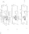
Anhand der in den Figuren dargestellten Ausführungsbeispiele soll die Erfindung näher erläutert werden. Es zeigen:With reference to the embodiments illustrated in the figures, the invention will be explained in more detail. Show it:
Wie die Zusammenschau der
Die erste Kante
An dieser Stelle sei darauf hingewiesen, dass sich die Erfindung hauptsächlich auf Bodenpaneele bezieht, jedoch Wandpaneele oder auch Deckenpaneele grundsätzlich auch durch die Erfindung erfasst sind. Die Begriffe „vertikal”, „horizontal”, „oben”, „unten” sollen sich dabei jeweils auf Bodenpaneele beziehen, die üblicherweise in der horizontalen Ebene auf einem Unterboden verlegt werden. Werden hingegen die Paneele als Wandpaneele eingesetzt, so sind die Begriffe „vertikal”, „horizontal”, „oben”, „unten” entsprechend umzudeuten.At this point it should be noted that the invention mainly relates to floor panels, but wall panels or ceiling panels are basically covered by the invention. The terms "vertical", "horizontal", "top", "bottom" are intended to refer to floor panels, which are usually laid in the horizontal plane on a subfloor. If, on the other hand, the panels are used as wall panels, the terms "vertical", "horizontal", "upper", "lower" are to be correspondingly reinterpreted.
Der Kante
Der feststehende Befestigungsteil
Wie der
Der flexible Befestigungsbereich
Im Gegensatz zum Ausführungsbeispiel der
Aus den
Neben der in den Clipfuß
Befestigungsnut
BezugszeichenlisteLIST OF REFERENCE NUMBERS
- 11
- erstes Paneelfirst panel
- 22
- zweites Paneelsecond panel
- 1010
- erste Kantefirst edge
- 1111
- untere Lippelower lip
- 1212
- Absatzparagraph
- 1313
- AbsatzverriegelungsflächeParagraph locking surface
- 1414
- Befestigungsnutmounting groove
- 1515
- obere Nutwandupper groove wall
- 1616
- untere Nutwandlower groove wall
- 1717
- Ausweichnutevasion
- 1818
- obere Nutwandupper groove wall
- 3030
- zweite Kantesecond edge
- 3131
- Verriegelungsnutlocking
- 3232
- Nutseitenwandgroove side wall
- 3333
- Sperrflächeblocking surface
- 3434
- Sperrnutlocking groove
- 3535
- Aktivierungsflächeactivation surface
- 3636
- Obere PasskanteUpper pass edge
- 5050
- Clipclip
- 5151
- Befestigungsteilattachment portion
- 5252
- bewegbarer Clipteilmovable clip part
- 5353
- Clipkopfclip head
- 5454
- ClipfußClipfuß
- 5555
- flexibler Verbindungsbereichflexible connection area
- 5656
- Drehachseaxis of rotation
ZITATE ENTHALTEN IN DER BESCHREIBUNG QUOTES INCLUDE IN THE DESCRIPTION
Diese Liste der vom Anmelder aufgeführten Dokumente wurde automatisiert erzeugt und ist ausschließlich zur besseren Information des Lesers aufgenommen. Die Liste ist nicht Bestandteil der deutschen Patent- bzw. Gebrauchsmusteranmeldung. Das DPMA übernimmt keinerlei Haftung für etwaige Fehler oder Auslassungen.This list of the documents listed by the applicant has been generated automatically and is included solely for the better information of the reader. The list is not part of the German patent or utility model application. The DPMA assumes no liability for any errors or omissions.
Zitierte PatentliteraturCited patent literature
- WO 2007/008139 A1[0002]WO 2007/008139 A1[0002]
- WO 2007/008139[0004]WO 2007/008139[0004]
Claims (9)
Translated fromGermanPriority Applications (6)
| Application Number | Priority Date | Filing Date | Title |
|---|---|---|---|
| DE102011056494ADE102011056494A1 (en) | 2011-12-15 | 2011-12-15 | Set of panels with clip |
| US13/483,974US8938929B2 (en) | 2011-12-15 | 2012-05-30 | Set of panels with clip |
| DE202012104530UDE202012104530U1 (en) | 2011-12-15 | 2012-11-22 | Set of panels with clip |
| EP12196324.3AEP2604771B1 (en) | 2011-12-15 | 2012-12-10 | Set of panels with clip |
| PCT/EP2012/005099WO2013087190A1 (en) | 2011-12-15 | 2012-12-10 | Set of panels with clip |
| US14/365,585US9518394B2 (en) | 2011-12-15 | 2012-12-10 | Set of panels with clip |
Applications Claiming Priority (1)
| Application Number | Priority Date | Filing Date | Title |
|---|---|---|---|
| DE102011056494ADE102011056494A1 (en) | 2011-12-15 | 2011-12-15 | Set of panels with clip |
Publications (1)
| Publication Number | Publication Date |
|---|---|
| DE102011056494A1true DE102011056494A1 (en) | 2013-06-20 |
Family
ID=47504636
Family Applications (2)
| Application Number | Title | Priority Date | Filing Date |
|---|---|---|---|
| DE102011056494AWithdrawnDE102011056494A1 (en) | 2011-12-15 | 2011-12-15 | Set of panels with clip |
| DE202012104530UExpired - LifetimeDE202012104530U1 (en) | 2011-12-15 | 2012-11-22 | Set of panels with clip |
Family Applications After (1)
| Application Number | Title | Priority Date | Filing Date |
|---|---|---|---|
| DE202012104530UExpired - LifetimeDE202012104530U1 (en) | 2011-12-15 | 2012-11-22 | Set of panels with clip |
Country Status (4)
| Country | Link |
|---|---|
| US (2) | US8938929B2 (en) |
| EP (1) | EP2604771B1 (en) |
| DE (2) | DE102011056494A1 (en) |
| WO (1) | WO2013087190A1 (en) |
Cited By (3)
| Publication number | Priority date | Publication date | Assignee | Title |
|---|---|---|---|---|
| US9518394B2 (en) | 2011-12-15 | 2016-12-13 | Pergo (Europe) Ab | Set of panels with clip |
| CN107109850A (en)* | 2014-12-22 | 2017-08-29 | 塞拉洛克创新股份有限公司 | Mechanical locking system for floor panels |
| CN107524271A (en)* | 2017-09-01 | 2017-12-29 | 安徽创能环保材料有限公司 | A kind of composite skirting for preventing contraction distortion |
Families Citing this family (27)
| Publication number | Priority date | Publication date | Assignee | Title |
|---|---|---|---|---|
| ATE467015T1 (en) | 2002-04-03 | 2010-05-15 | Vaelinge Innovation Ab | FLOOR PANEL WITH INTEGRATED CONNECTING MEANS AND METHOD FOR THE PRODUCTION THEREOF |
| US11725394B2 (en) | 2006-11-15 | 2023-08-15 | Välinge Innovation AB | Mechanical locking of floor panels with vertical folding |
| US8689512B2 (en) | 2006-11-15 | 2014-04-08 | Valinge Innovation Ab | Mechanical locking of floor panels with vertical folding |
| BR112012016569A2 (en) | 2010-01-12 | 2016-04-05 | Vaelinge Innovation Ab | mechanical locking system for floor panels |
| CA2786680C (en) | 2010-02-04 | 2018-06-12 | Vaelinge Innovation Ab | Mechanical locking system for floor panels and a tongue therefore |
| UA114715C2 (en) | 2011-07-05 | 2017-07-25 | Сералок Інновейшн Аб | Mechanical locking of floor panels with a glued tongue |
| US9725912B2 (en) | 2011-07-11 | 2017-08-08 | Ceraloc Innovation Ab | Mechanical locking system for floor panels |
| US8650826B2 (en) | 2011-07-19 | 2014-02-18 | Valinge Flooring Technology Ab | Mechanical locking system for floor panels |
| US8857126B2 (en) | 2011-08-15 | 2014-10-14 | Valinge Flooring Technology Ab | Mechanical locking system for floor panels |
| BE1020433A3 (en)* | 2012-01-05 | 2013-10-01 | Flooring Ind Ltd Sarl | PANEL. |
| US9394698B2 (en) | 2012-02-23 | 2016-07-19 | Admiral Composite Technologies, Inc. | Deck system and components |
| US10760283B2 (en)* | 2012-02-23 | 2020-09-01 | Admiral Composite Technologies, Inc. | Deck system and components |
| CN104582916A (en)* | 2012-06-19 | 2015-04-29 | 瓦林格创新股份有限公司 | Method for dividing a panel into a first panel and a second panel, method of forming a mechanical locking system for locking the first and second panels, and building panels |
| PL2923012T3 (en) | 2012-11-22 | 2020-04-30 | Ceraloc Innovation Ab | Mechanical locking system for floor panels |
| PT3014034T (en)* | 2013-06-27 | 2019-11-29 | Vaelinge Innovation Ab | Building panel with a mechanical locking system |
| DE102013108539A1 (en)* | 2013-08-07 | 2015-02-12 | Hamberger Industriewerke Gmbh | Connection and locking element |
| WO2015070890A1 (en)* | 2013-11-12 | 2015-05-21 | Grigorij Wagner | Flooring component |
| EP2915934A1 (en)* | 2014-03-06 | 2015-09-09 | Flooring Industries Ltd., SARL. | Set consisting of panels with a locking element |
| US10246883B2 (en) | 2014-05-14 | 2019-04-02 | Valinge Innovation Ab | Building panel with a mechanical locking system |
| CN106460394B (en) | 2014-05-14 | 2019-09-17 | 瓦林格创新股份有限公司 | Building panel with mechanical locking system |
| JP6900313B2 (en) | 2014-11-27 | 2021-07-07 | ベーリンゲ、イノベイション、アクチボラグVaelinge Innovation Ab | Mechanical locking system for floor panels |
| USD876673S1 (en)* | 2017-08-31 | 2020-02-25 | Chia-Ming Chang | Plank unit |
| US11060302B2 (en) | 2019-01-10 | 2021-07-13 | Valinge Innovation Ab | Unlocking system for panels |
| BE1027032B1 (en)* | 2019-02-07 | 2020-09-07 | Flooring Ind Ltd Sarl | Panel and trim formed with such panels |
| DE102019134858A1 (en)* | 2019-12-18 | 2021-06-24 | Windmöller Gmbh | Floor panel with separate clip for vertical locking |
| US12071769B2 (en)* | 2021-02-03 | 2024-08-27 | Valinge Innovation Ab | Building panels comprising a locking device |
| DE202021003901U1 (en)* | 2021-12-30 | 2022-02-09 | Surface Technologies Gmbh & Co. Kg | Set of two panels to cover a surface and a panel connector, panel connector and use of a panel connector |
Citations (3)
| Publication number | Priority date | Publication date | Assignee | Title |
|---|---|---|---|---|
| WO2007008139A1 (en) | 2005-07-11 | 2007-01-18 | Pergo (Europe) Ab | A joint for panels. |
| EP2017403A2 (en)* | 2007-07-20 | 2009-01-21 | Moritz Mühlebach | Flooring system |
| DE102007042250A1 (en)* | 2007-09-06 | 2009-03-12 | Flooring Technologies Ltd. | Device for connecting and locking two building panels, in particular floor panels |
Family Cites Families (21)
| Publication number | Priority date | Publication date | Assignee | Title |
|---|---|---|---|---|
| US5502939A (en)* | 1994-07-28 | 1996-04-02 | Elite Panel Products | Interlocking panels having flats for increased versatility |
| ES2378330T3 (en) | 2004-10-22 | 2012-04-11 | Välinge Innovation AB | A method of providing floor panels with a mechanical locking system |
| US7841144B2 (en)* | 2005-03-30 | 2010-11-30 | Valinge Innovation Ab | Mechanical locking system for panels and method of installing same |
| SE529506C2 (en)* | 2006-02-03 | 2007-08-28 | Pergo Europ Ab | A joint cover for panels |
| BE1017157A3 (en) | 2006-06-02 | 2008-03-04 | Flooring Ind Ltd | FLOOR COVERING, FLOOR ELEMENT AND METHOD FOR MANUFACTURING FLOOR ELEMENTS. |
| US8689512B2 (en)* | 2006-11-15 | 2014-04-08 | Valinge Innovation Ab | Mechanical locking of floor panels with vertical folding |
| DE102006057491A1 (en)* | 2006-12-06 | 2008-06-12 | Akzenta Paneele + Profile Gmbh | Panel and flooring |
| SE531111C2 (en)* | 2006-12-08 | 2008-12-23 | Vaelinge Innovation Ab | Mechanical locking of floor panels |
| US8220217B2 (en)* | 2007-07-20 | 2012-07-17 | Innovaris Ag | Flooring system |
| DE102007043308B4 (en)* | 2007-09-11 | 2009-12-03 | Flooring Technologies Ltd. | Device for connecting and locking two building panels, in particular floor panels |
| BE1018600A5 (en) | 2007-11-23 | 2011-04-05 | Flooring Ind Ltd Sarl | FLOOR PANEL. |
| BE1018627A5 (en)* | 2009-01-16 | 2011-05-03 | Flooring Ind Ltd Sarl | FLOOR PANEL. |
| EP2233195A1 (en) | 2009-03-27 | 2010-09-29 | Meridionale Impianti S.p.A. | System and method for recovering hydrogen from exhausted gas of epitaxial processes and other industrial processes |
| DE102009022483A1 (en) | 2009-05-25 | 2010-12-02 | Pergo (Europe) Ab | Set of panels, in particular floor panels |
| DE102009034902B4 (en) | 2009-07-27 | 2015-10-01 | Guido Schulte | Surface made of mechanically interconnectable panels |
| PL2333195T3 (en)* | 2009-12-14 | 2014-12-31 | Barlinek Sa | Floor made of floor panels with separate connection components |
| BR112012017589B1 (en)* | 2010-01-14 | 2019-11-12 | Spanolux N V Div Balterio | floor panel mounting |
| DE102010004717A1 (en)* | 2010-01-15 | 2011-07-21 | Pergo (Europe) Ab | Set of panels comprising retaining profiles with a separate clip and method for introducing the clip |
| CN104831904B (en)* | 2010-05-10 | 2017-05-24 | 佩尔戈(欧洲)股份公司 | Set of panels |
| UA109938C2 (en)* | 2011-05-06 | 2015-10-26 | MECHANICAL LOCKING SYSTEM FOR CONSTRUCTION PANELS | |
| DE102011056494A1 (en) | 2011-12-15 | 2013-06-20 | Pergo (Europe) Ab | Set of panels with clip |
- 2011
- 2011-12-15DEDE102011056494Apatent/DE102011056494A1/ennot_activeWithdrawn
- 2012
- 2012-05-30USUS13/483,974patent/US8938929B2/enactiveActive
- 2012-11-22DEDE202012104530Upatent/DE202012104530U1/ennot_activeExpired - Lifetime
- 2012-12-10USUS14/365,585patent/US9518394B2/enactiveActive
- 2012-12-10EPEP12196324.3Apatent/EP2604771B1/ennot_activeNot-in-force
- 2012-12-10WOPCT/EP2012/005099patent/WO2013087190A1/enactiveApplication Filing
Patent Citations (3)
| Publication number | Priority date | Publication date | Assignee | Title |
|---|---|---|---|---|
| WO2007008139A1 (en) | 2005-07-11 | 2007-01-18 | Pergo (Europe) Ab | A joint for panels. |
| EP2017403A2 (en)* | 2007-07-20 | 2009-01-21 | Moritz Mühlebach | Flooring system |
| DE102007042250A1 (en)* | 2007-09-06 | 2009-03-12 | Flooring Technologies Ltd. | Device for connecting and locking two building panels, in particular floor panels |
Cited By (4)
| Publication number | Priority date | Publication date | Assignee | Title |
|---|---|---|---|---|
| US9518394B2 (en) | 2011-12-15 | 2016-12-13 | Pergo (Europe) Ab | Set of panels with clip |
| CN107109850A (en)* | 2014-12-22 | 2017-08-29 | 塞拉洛克创新股份有限公司 | Mechanical locking system for floor panels |
| CN107109850B (en)* | 2014-12-22 | 2019-10-25 | 塞拉洛克创新股份有限公司 | Mechanical locking system for floor panels |
| CN107524271A (en)* | 2017-09-01 | 2017-12-29 | 安徽创能环保材料有限公司 | A kind of composite skirting for preventing contraction distortion |
Also Published As
| Publication number | Publication date |
|---|---|
| US8938929B2 (en) | 2015-01-27 |
| US9518394B2 (en) | 2016-12-13 |
| WO2013087190A1 (en) | 2013-06-20 |
| EP2604771A1 (en) | 2013-06-19 |
| US20150075104A1 (en) | 2015-03-19 |
| DE202012104530U1 (en) | 2013-01-29 |
| EP2604771B1 (en) | 2018-08-22 |
| US20130152500A1 (en) | 2013-06-20 |
Similar Documents
| Publication | Publication Date | Title |
|---|---|---|
| DE102011056494A1 (en) | Set of panels with clip | |
| DE10159284B4 (en) | Building plate, in particular floor panel | |
| EP2668350B1 (en) | Panel | |
| DE102007018309B4 (en) | Connection for plate-shaped components | |
| DE102006006124A1 (en) | Device for locking two building panels | |
| DE102007049792A1 (en) | connection | |
| DE10031639A1 (en) | Floor plate | |
| DE202007018662U1 (en) | Panel, in particular floor panel | |
| DE1509841A1 (en) | Portable floor | |
| EP2333195A1 (en) | Floor made of floor panels with separate connection components and method for laying floor panels | |
| DE202007014493U1 (en) | Set of tabular panels with movable locking element | |
| EP2915934A1 (en) | Set consisting of panels with a locking element | |
| EP2292868B1 (en) | Panels joinable to each other by lowering | |
| DE102007019786B4 (en) | Connection for plate-shaped components | |
| DE102004012582A1 (en) | panel member | |
| DE202007012734U1 (en) | Profile strip, in particular skirting board | |
| DE102013106251A1 (en) | Mounting system for a floor covering | |
| DE102004029879B4 (en) | Panels with borders, especially for walls and ceilings | |
| DE102015106035A1 (en) | Connection for plate-shaped components and spring | |
| DE202008000534U1 (en) | Profile rail system for covering at least one covering edge | |
| DE202008005295U1 (en) | connection | |
| DE10253236B4 (en) | Floor panel and method for laying a floor panel | |
| DE202008006250U1 (en) | connection | |
| DE102016100407A1 (en) | Floor system for vehicles | |
| DE102005061645B4 (en) | Flooring with panels which can be removed at any point from the composite |
Legal Events
| Date | Code | Title | Description |
|---|---|---|---|
| R012 | Request for examination validly filed | ||
| R082 | Change of representative | Representative=s name:MANITZ FINSTERWALD PATENT- UND RECHTSANWALTSPA, DE Representative=s name:MANITZ FINSTERWALD PATENTANWAELTE PARTMBB, DE | |
| R016 | Response to examination communication | ||
| R119 | Application deemed withdrawn, or ip right lapsed, due to non-payment of renewal fee |